1. Introduction
Modern land surveying in the mining industry is based on input data acquired from both classical methods (leveling, tacheometry) and modern solutions: digital photogrammetry, measurements with the use of Global Navigation Satellite Systems (GNSS), and laser scanning. These data allow the preparation of maps documenting the deposit, situational plans illustrating the advancement of mining operations, or 3D visualizations showing planned reclamation forms. Commonly used worldwide, these surveying techniques have both advantages and disadvantages. Their implementation typically depends on the level of detail expected in the mining map, and thus on the accuracy of a particular measurement method and on the duration of the measurement process [
1,
2,
3,
4,
5,
6,
7].
Classical surveying methods allow highly accurate and precise measurement results. The vertical displacements can be recorded with the use of classical and precise leveling with accuracy levels of several millimeters [
8] or under 1 mm [
9], respectively. Displacements on the surface of a mining area can be observed in 3D. For this purpose, total station measurements are combined with static GNSS measurements [
10].
One of the interesting solutions, which is an extension of satellite measurements, is the use of the so-called pseudolites. Pseudoliths are terrestrial transmitters that are transmitting satellite-like signals to assist satellite navigation in areas depleted in terms of signal availability from traditional satellites. The areas of application of this solution are opencast mines with steep and high slopes, where poor satellite availability due to obscured horizon limits the ability to receive the GNSS signal [
11].
Recent years have also been marked by the dynamic development of measurement technology based on ground-based radar. In mining, both underground and opencast, it is mainly used to monitor the stability of slopes or to measure surface deformation [
12], rarely to monitor the exploitation progress or build the 3D models of mining area.
Observations in the form of a 3D continuous surface allow the construction of a 3D model from the land or aerial level [
13,
14]. Such measurements typically involve UAV photogrammetry techniques [
15] and LiDAR, mainly ALS, and increasingly often UAV [
16]. With the use of such techniques, the model can be quickly reconstructed with an accuracy of below 7 cm [
17], which, of course, depends on laser scanner accuracy itself as well as resolution of the scan. In the case of UAVs, the main factor determining the accuracy of the calculated model is so-called ground sampling distance (GSD; it is the distance between pixel centers measured on the ground). Updating 3D mine models does not require as high accuracies as in the case of monitoring subsidence movements or slope stability [
18].
Limitations of the above methods also need to be stressed. Most importantly, leveling, total station (excluding situations when prisms are stabilized on the measured points) or photogrammetry survey methods cannot be used without the natural and/or an artificial source of light, which fact practically disqualifies these methods from being used at night or would entail the need to provide prohibitively expensive artificial lighting. Atmospheric conditions (e.g., clouds, wind or atmospheric precipitation) are also a considerable limitation, which may contribute to a lower quality of the measurement results or even prevent the measurements entirely. On the other hand, the GNSS measurements—and more specifically their precision—depend on the availability of satellite constellations, and the use of the so-called differential corrections also increases the cost of the entire procedure. Importantly, in the case of relatively deep open-pit excavations, which may have obstructed views of the satellites, the measurement accuracy is lowered. Recent developments in geomatics have allowed the use of a wide range of sensors to record the geometry of both objects and other features on land [
19]. Currently, hybrid sensors such as Mobile LiDAR Systems (MLS) provide additional quality to the inventorying process of mining facilities, as they offer solutions which prove flexible in terms of accuracy, resolution and access to areas which are otherwise inaccessible to vehicles [
20].
The aim of this article is to present an MLS-based measurement solution for open-pit mining industry. The proposed technique employs a Riegl VMZ 400i measurement platform and a Velodyne LiDAR sensor in the Simultaneous Localization and Mapping (SLAM) approach to data acquisition and localization. The main concept presented in this paper utilizes a high-resolution, precise geometrical data source (MLS) for creating the initial model of the mine and updating it periodically using low-cost sensor and open-source algorithms. Such solution could provide information about near real-time tracking of the progress of mining works and allow e.g. volumetric calculations of the excavated material.
The measurements from both systems provide data for developing a digital representation (the so-called Digital Twin) of the geometry of a mining excavation, which may be used over the mine life cycle in such applications as monitoring the exploitation state of the mining excavation, performed in the form of cyclical measurements in order to control and optimize (improve) the efficiency of the mining process, constructing a management model of an active or a closed excavation, providing information about the state of the closed excavation and constructing its revitalization model. The methods here proposed allow quick access to the excavation-related data with a minimum workload required from an operator to acquire and process the data and, as such, they reflect well the principles of Industry 4.0 [
21,
22,
23,
24,
25].
2. Materials and Methods
The main idea behind this study is based on the use of a point cloud obtained from a RIEGL VMZ commercial hybrid laser-scanning platform equipped with a VZ400i scanner mounted on an off-road vehicle. The system allows a quick acquisition of three-dimensional data about the analyzed object, in this case about a granite quarry. The concept of integrating a high-resolution MLS approach with full georeferencing is a base for further analyses of sensors used in acquisitions of 3D geometrical data related to the mine. The experiment was performed with a low-cost Velodyne scanning sensor was, in a handheld SLAM MLS approach. Tests of such a solution consist in obtaining three-dimensional information about the mine (a point cloud) over a time
t0 and in comparing the results with the results from the Velodyne instrument. Consecutive measurements performed in time
t1,
t2, …
tn may be in the form of the so-called additional measurements with the use of low-cost handheld MLS sensor.
Figure 1 is a schematic diagram of the measurements.
2.1. Description of the Study Area
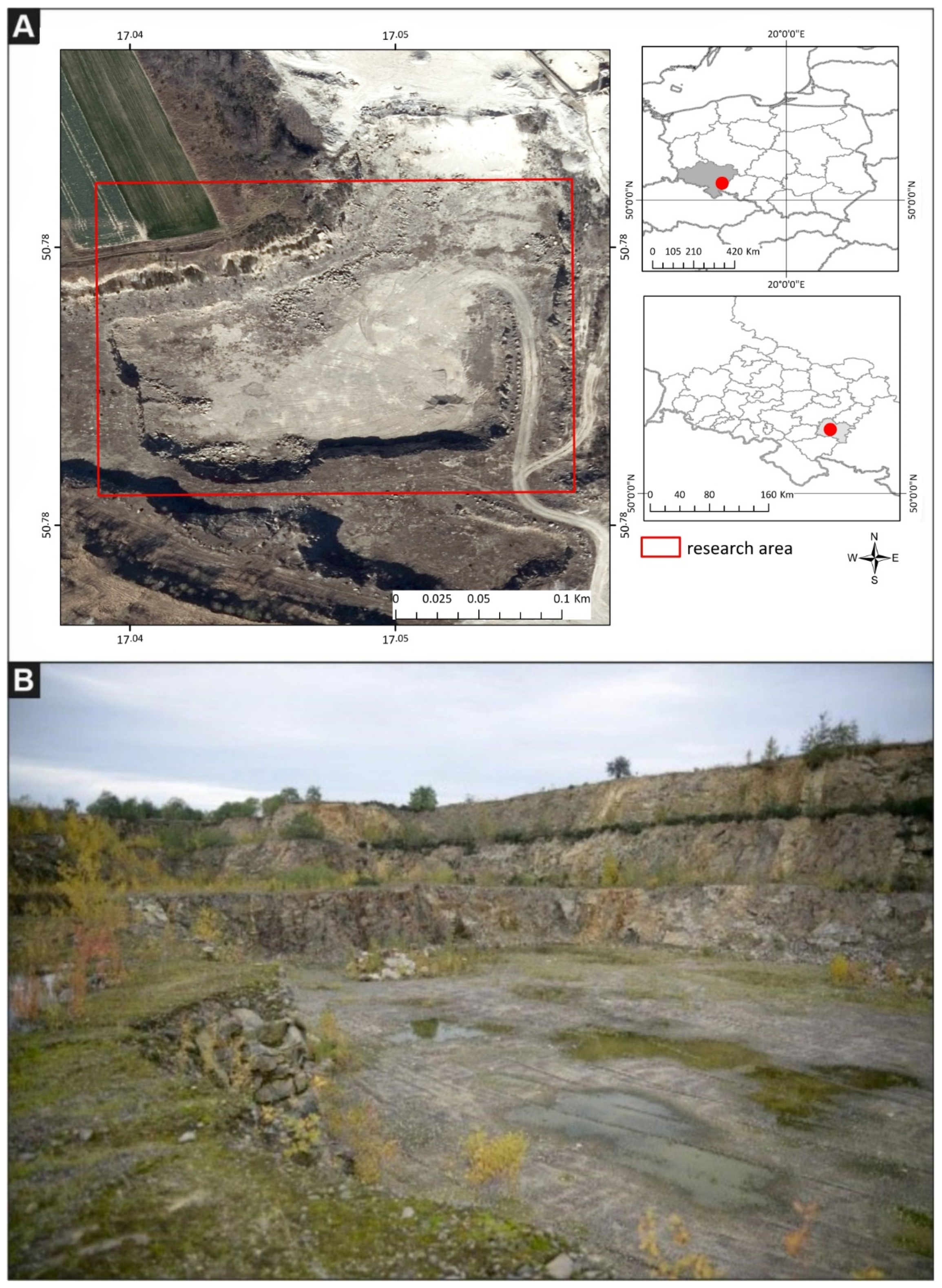
This experiment was performed on the Mikoszów granite deposit located south-east of the town of Strzelin (Lower Silesia, SW Poland;
Figure 2). Based on lease no. 10/2001, until 2016 Mineral Polska Sp. z o.o. mined the deposit for granite and gneiss. The company is planning to renew its lease to mine the deposit with the same technology. The planned output is 800,000 Mg per year. The geological resources of the Mikoszów deposit are 23,249,840 Mg (as per 31 December 2015). Until 2016, the deposit was mined with the use of a mixed wall-shortwall system with parallel advancement of the mining front. The deposit was extracted by drilling and blasting with the use of explosive materials and short and long drillholes. The mined material was loaded with loaders or excavators into mobile hoppers of crushing/sorting machines or into technological vehicles which transported it to processing devices located outside the mining plant. The processed stone was loaded with a loader from the storage site onto vehicles provided by the clients [
26,
27,
28,
29].
2.2. Mobile Laser Scanning
The literature mentions a number of mobile and autonomous mapping platforms which can collect data form indoor mapping [
30]. The main advantage of the MLS system mounted on vehicle lies in the sensor fusion. The mobile mapping platform is equipped with GNSS, IMU (Inertial Measurement Unit) and DMI (Distance Measurement Indicator) sensors. The GNSS observations are essential in the kinematic mode of Lidar data acquisition. For a perfect trajectory, both static and dynamic alignment is required. If this condition is not met, the derived point clouds are distorted and lose spatial consistency. MLS data acquisition in urban areas may be affected by multipath effects and by signal obstruction due to buildings. This can lead to inaccurate GNSS measurements and, therefore, errors in the estimated trajectory [
31]. Kukko et al. (2012) presented on-board sensors integration and MLS platform data acquisition from a vehicle, boat-mounted MLS for mapping fluvial processes and snowmobile application for studying the characteristics of and changes in snow cover. The main advantage of such mobile scanning platforms include fast and smart data collection. In MLS, the slightly elevated point of view gives the advantage of observing vertical surfaces with angle of incidence close to 0°.
The mobile laser scanning technique allows fast and rapid 3D data acquisition in mining areas. In this technique, the measurement is performed with a scanner, and the time-dependent positions of the scanner are also recorded. In comparison to the standard laser scanning technique (Terrestrial Laser Scanning—TLS), in which the measuring instrument is located on an elevating tripod, the MLS has a similar incidence angle of the laser beam with respect to the scanned surface. However, as the system is mobile, it allows the acquisition of data for areas that were not visible from the perspective of the previous location of the scanning platform. The point cloud thus obtained has a relatively smaller number of occlusions and gaps. Examples of the integration of MLS data for the purpose of geological structure mapping were described in [
32]. What is more, the recordings of LiDAR MLS datasets provide an alternative point of view. The average height above ground is greater than in the case of TLS scanning stations mounted on tripods. The density of the scan is similar to that of the TLS scan, and the density of the MLS records depends on the movement speed of the scanning platform.
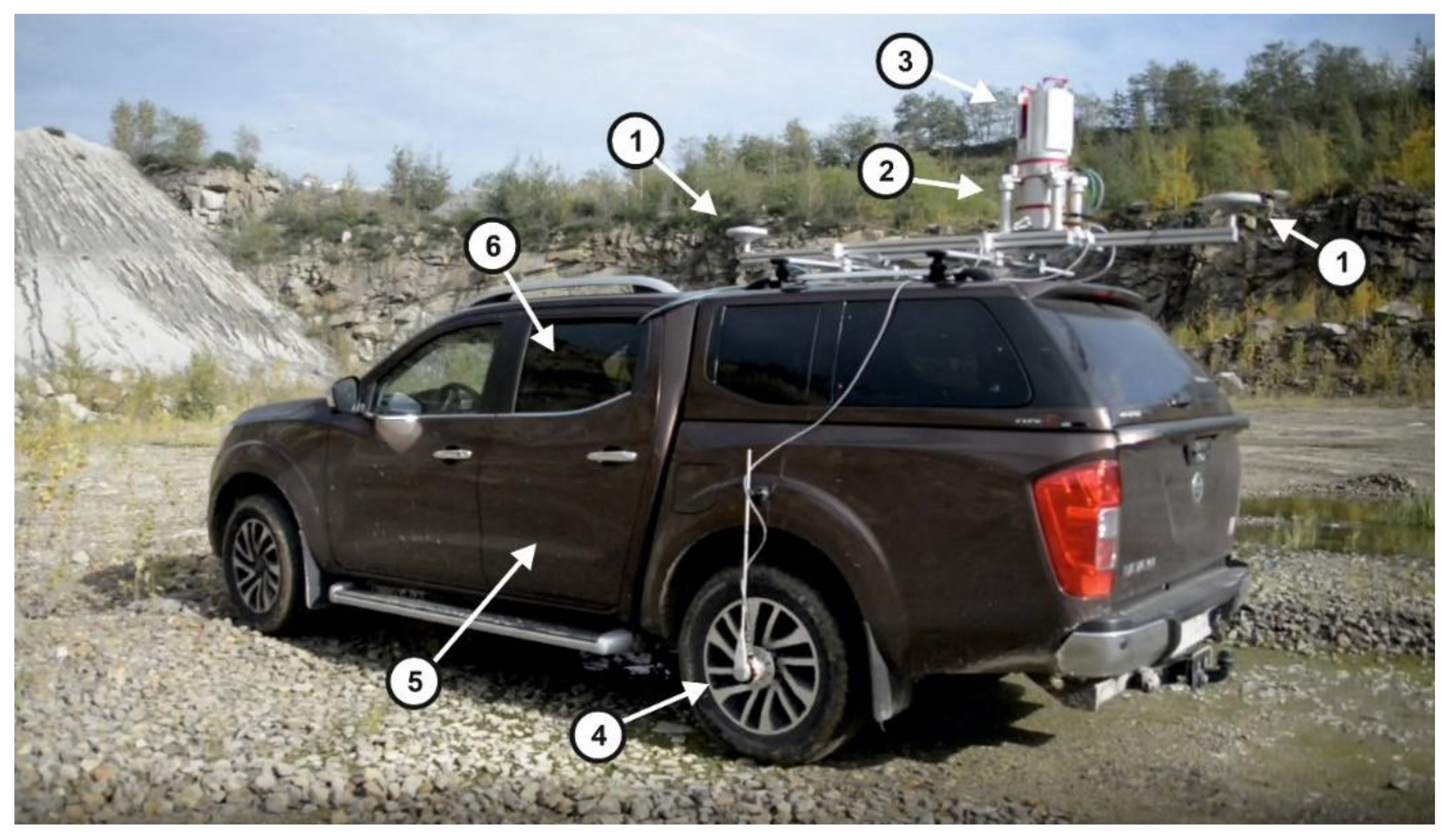
2.2.1. The Riegl VMZ Mobile Scanning Platform
The MLS Riegl VMZ400i system used in the study comprised: a GNSS system based on simultaneous trajectory measurements from two antennas, an IMU, a DMI and a laser scanner (
Figure 3).
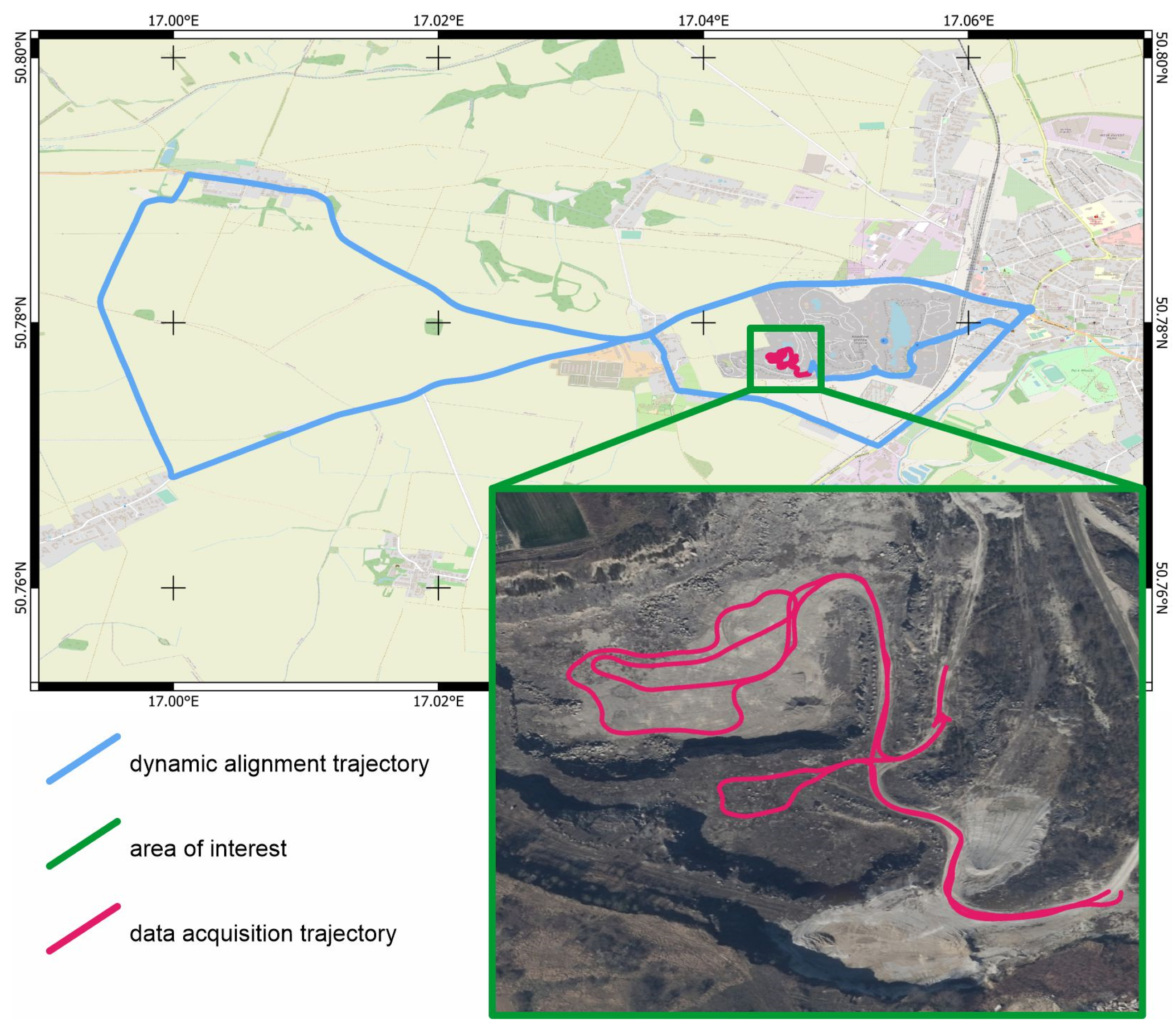
2.2.2. Acquisition of MLS Data
The MLS data were recorded for the entire area of the Mikoszów mine and its vicinity. The recording process was performed with the use of the Riegl VMZ 400i hybrid laser scanning system set in the radar mode. The data acquisition process in this mode takes place while the scanner rotates 360° (around it’s Z axis) and the whole MLS system drives along the planned trajectory as well. For the purpose of this article, an area of interest (AOI) was defined and indicated in yellow in
Figure 4.
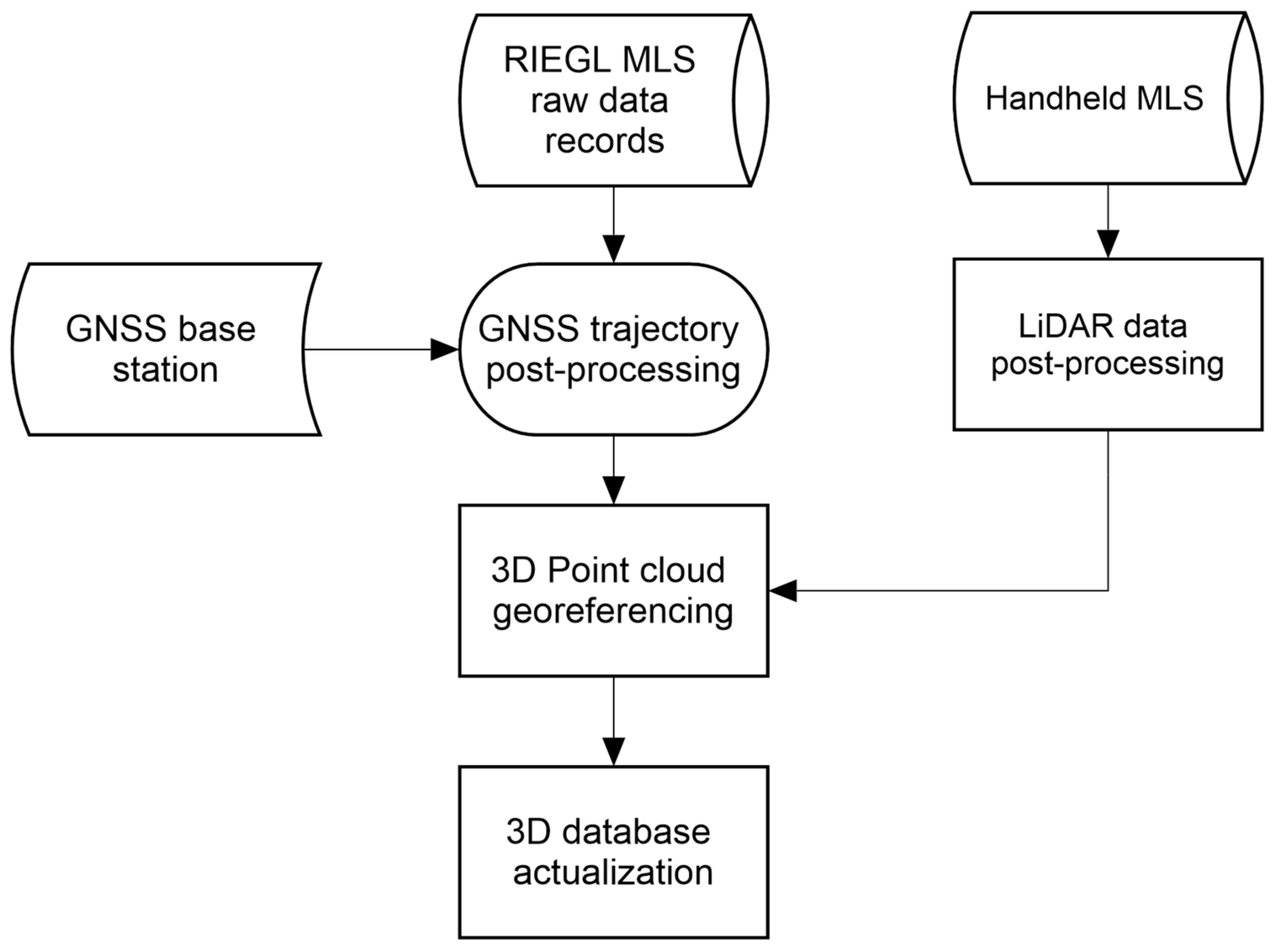
The procedure of recording MLS data, which is based on GNSS measurements, required the position of the MLS platform to be acquired around the analyzed mine in the form of a dynamic alignment trajectory loop. All of the works related to the GNSS trajectory measurements were performed in the Applanix PosPac MMS software, using the In-Fusion single base adjustment solution. The procedure allowed the GNSS observations of the platform to be linked with the BASE receiver, which was located in the central part of the mine pit, on its southern slope. The In-Fusion solution integrates the GNSS sensor with displacements recorded by the IMU and the DMI. The DMI allows precise information on the start and stop of the platform to be obtained from a source different to the GNSS.
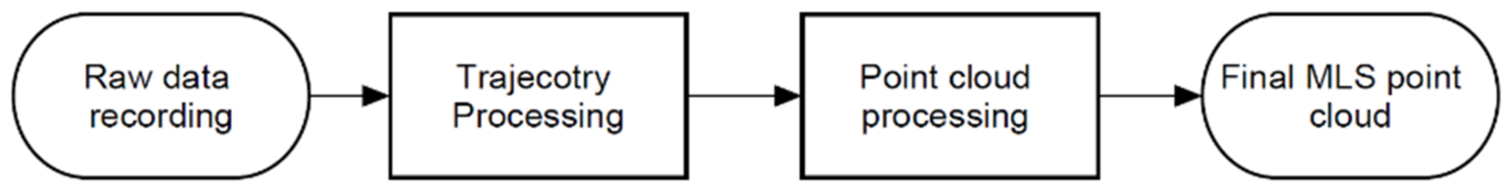
Figure 5 shows a schematic diagram of the MLS data processing procedure.
The MLS measurements and their processing procedure are based on a precise measurement of the time recorded by the measurement system. The processing of a point cloud consists in overlaying individual scan lines on the 3D trajectory in time. The measurement accuracy of the MLS Riegl VMZ 400i is ensured owing to two GNSS antennas that measure the GAMS azimuth (GNSS Azimuth Measurement System). This approach helps eliminate inertial drift errors that are typically produced in a single-antenna approach). GAMS determines the movement direction of the vehicle very accurately regardless of its speed, resulting in the best possible heading accuracy and the best performance in any demanding environment, e.g., with an insufficient number of satellites. The full technical data are shown in
Table 1.
2.3. Handheld Mobile Laser Scanning
Another MLS technique is based on small mobile laser scanners (originally used in robotics) and on the SLAM technology. The technology consists in simultaneous, iterative determining the position of the observer and in constructing a map (or a 3D model) of the surrounding area. SLAM algorithms are mainly based on data obtained from laser scanners, stereoscopic cameras or monocular cameras. Solutions of this type are normally used in GNSS-denied environments, but if such limitations are not present, the position indicated by the GNSS receiver can be additionally used to improve the quality of SLAM-based positioning [
34,
35]. The pose of the observation unit and its movement can be additionally determined from the input data provided by other sources, such as IMU sensors [
36,
37] or wheel odometry [
38]. SLAM algorithms are found in numerous implementations and are frequently based on the Kalman filters [
35,
39], graphs [
40,
41], or voxels [
42].
SLAM functions by solving two basic problems:
Estimation of consecutive transformations from the coordinate systems (related to the operator), containing point clouds obtained at times ti and ti+1, into a uniform global coordinate system—this process is referred to as laser odometry,
Identification of the so-called loop closure, or return visit locations. In the case when point clouds obtained in non-consecutive time points ti and tj correspond to identical actual locations, another condition, different than the transformations calculated from the consecutive scans, can be added to the bundle adjustment of the measurement trajectory. This fact significantly improves the quality and the robustness of the results obtained from the SLAM algorithm, and eliminates errors related to the position drifting in time due to the relative identification of consecutive observing positions.
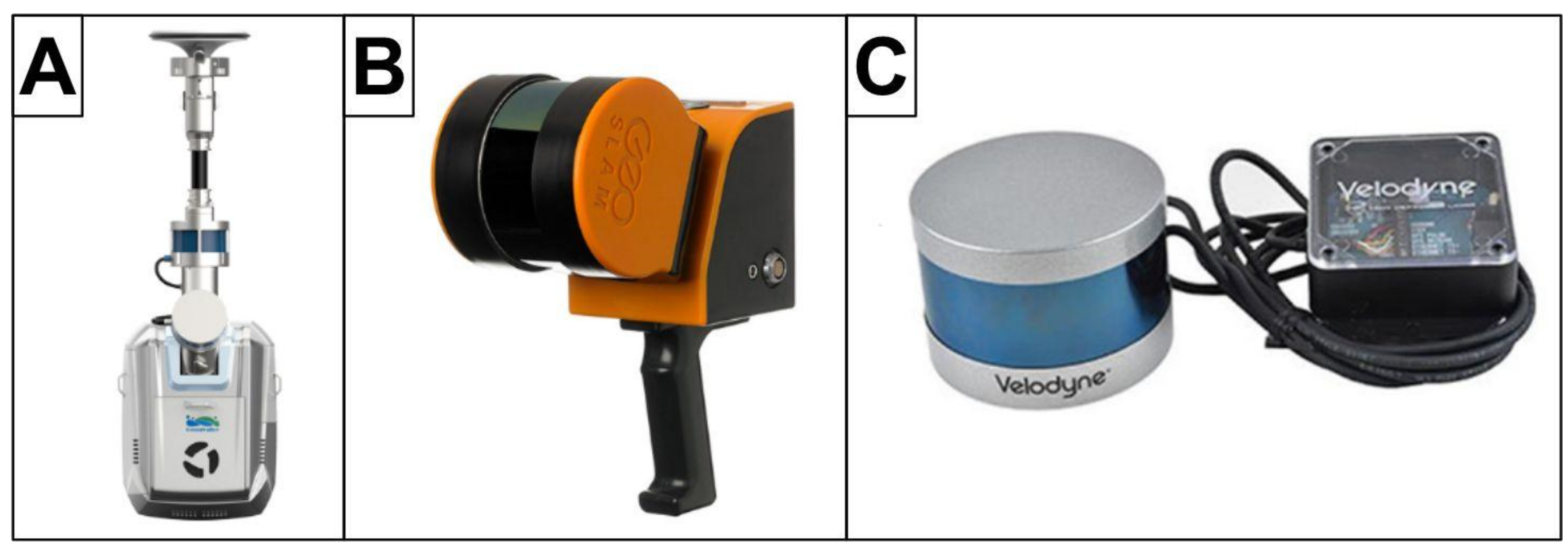
MLS systems based on small portable laser scanners are now most typically offered as backpack systems, frequently integrated with cameras and GNSS receivers (
Figure 6A) or as handheld scanners (
Figure 6B). The measurement system can be further simplified by using only a small LiDAR sensor carried by an operator (
Figure 6C). Despite a different approach to the sensor arrangement, the systems are, in fact, similar and share the measurement methodology. Therefore, later in this article they will be synonymously referred to as handheld laser scanners.
The measurement is performed by an operator who carries a handheld or a backpack scanner and walks around the surveyed area. The latter factor most significantly distinguishes this solution from mobile or stationary laser scanners. On the one hand, it is a limitation, as the range and speed of the measurement is smaller than in the case of mobile scanning performed from a wheeled vehicle, drone or robot. Unlike in the above solutions, the measurement process cannot be automatized. Nevertheless, the operator can easily and naturally adjust the density of the point cloud in desired areas, by prolonging the data acquisition time. Modern SLAM algorithms also allow consecutive scans to be recorded and 3D models of the area to be constructed in real time. In combination with visualization techniques (e.g., on a tablet), this function allows a more effective and precise coverage of the surveyed area. Another advantage lies in the fact that the operator does not have to be highly qualified. Data processing is automatic, and therefore the survey can be performed by a person not familiar with the SLAM technology, or by an autonomous vehicle. Only the post-processing of the data (correctness verification and adding loop closures, georeferencing, improving the quality of defining the measurement trajectory), which allows an improved quality and accuracy of the resultant point cloud, requires higher competences and the ability to use a particular software.
Importantly, the measurement trajectory and thus the resultant point cloud, is biased with a drift error, i.e., a measurement uncertainty which increases with time. As already mentioned, this error is limited by revisiting the previously scanned locations and by allowing the SLAM algorithm to perform loop closure. However, for this to be possible, the measurement path needs to be planned in such a manner that the already surveyed locations are revisited at a sufficient frequency [
43,
44].
Many of the SLAM algorithms which process 3D data provide lidar odometry with the use of the Generalized Iterative Closest Point (GICP) algorithm. Ren et al. [
45] proposed a modification of this algorithm, allowing for the extraction of the ground plane from individual scans and using them as landmarks in order to increase the robustness of the algorithm. Subsequently, the researchers compared the proposed method with other state-of-the-art algorithms which use a lidar sensor only (VLP-16). These included Lidar Odometry and Mapping (LOAM) [
46], Lightweight and Ground-Optimized Lidar Odometry (LeGO-LOAM) [
47] and Berkeley Localization and Mapping (BLAM) [
48]. The proposed algorithm was designed for the consistent localization of autonomous vehicles in roadways and tunnels of an underground mine. Nevertheless, tests performed on two paths inside a building and on two paths in an underground mine indicate that the results in the mining environment are significantly worse. The authors stress the significance of the loop closure and of introducing plane constraints in obtaining satisfactory results from the tested algorithms.
Vasenna & Clerici [
49] introduce a concept of integrating data obtained from classical point cloud construction methods (TLS and UAV photogrammetry) with data from a commercial, backpack SLAM system manufactured by Heron. The aim of the study was to verify the possibility of locating the SLAM operator in an open-pit mine environment previously modeled with the use of classical methods. Having successfully verified this possibility, the authors proposed a methodology for using SLAM in detecting changes of excavation geometry. The estimated accuracy of such detections is above 3–4 cm.
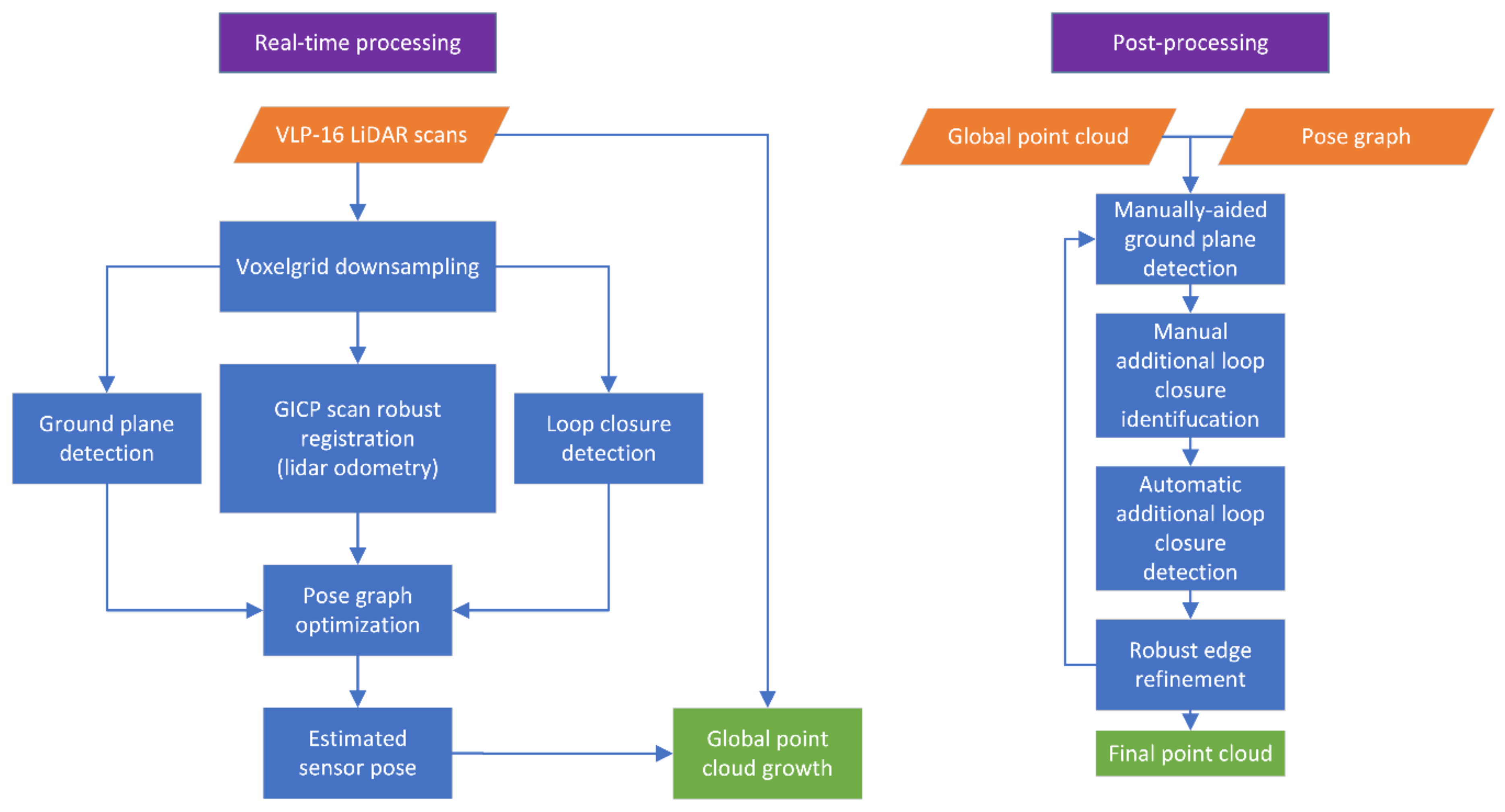
In this study, HDL-SLAM algorithm framework, proposed by Koide et al. [
50], has been used. It is based on pose graph optimization and allows a significant elasticity in selecting parameters (for both the LiDAR odometry and the loop closure) and additional conditions in the SLAM algorithm, such as ground plane constraint, GNSS constraint, LiDAR odometry, estimation method and numerous robust kernels. Moreover, the authors provided an interactive graph editing program, which allows the resultant trajectory and point cloud to be improved in the post-processing stage with the use of manual edition tools, loop closure densification and edge refinement. The general concept of the data processing acquired by handheld SLAM is presented in
Figure 7. The framework was selected due to its multiple options, which enable adjustments to the conditions of a particular surveyed object, and also due to the open-source implementation in the Robot Operating System (ROS) [
51], which allows seamless integration with the LiDAR sensor and with the remaining software installed on a Linux-run laptop computer. The measurements were performed with the use of the Velodyne VLP-16. Its parameters are presented in
Table 2.
3. Results
The fact that the hybrid Riegl VMZ 400i scanner was installed on a Nissan Navara 4 × 4 off-road vehicle enabled the operator to reach the lowest level of the Mikoszów mine pit, which was the area subjected to further analysis, and to enter the otherwise least accessible locations. The system functions owing to the fact that the scanner was installed above the vehicle and the view of the satellites remained unobstructed. The unfavorable Positional Dilution Of Precision (PDOP) and the insufficient number of satellites visible in the vicinity of the vertical slopes was compensated for by data from IMU and DMI. The geometrical processing of the data was performed in parallel with preliminary filtration. The extraction parameters consisted of such LiDAR signal attributes as reflectance, distance, deviation. The next stage consisted of data filtering. The resultant point cloud represented all classes and comprised above 9.7 × 10
7 points (
Table 3). The resultant point cloud was not filtered in order to classify the point cloud in accordance with the ISPRS .las recommendations.
Figure 8 is a visualization in the form of a raster of the measurement range. The recorded MLS point cloud is a set of XYZ 3D data and a series of parameters such as amplitude and reflectance.
The handheld LiDAR measurements were performed by an operator who carried the LiDAR scanner (Velodyne VLP-16) in his hand. The scanner was connected to a laptop in the backpack. The data were recorded on the laptop, in rosbag format in ROS. The measurement covered the area of the lowest level of the open-pit and was performed by an operator walking around the mine. Attention was paid to intentionally form numerous smaller measurement loops and to stop the measurement in the vicinity of the start location in order to achieve a robust point cloud by forming a loop closure. The measurement continued for 16 min and 54 s, during which a total of 10,676 scans were acquired.
The measurement results were subsequently processed offline with the use of SLAM algorithms in order to combine them in a consistent point cloud. The preliminary estimation of the measurement trajectory was performed as the scans were replayed with actual speed. In the next step, the trajectory was manually improved in the post-processing mode by additionally indicating points which correspond to a flat terrain and by indicating clear revisit moments not identified automatically. Subsequently, automatic trajectory improvement methods were used to detect additional loop closures and robust refinement of pose graph edges. This process was iterated until satisfying results were obtained (no deviating observations (at 3 sigma), the trajectory visually corresponds to the actual measurement path). In effect, the obtained trajectory allowed the point clouds to be recorded from all scans. The resultant cloud, comprising 2,241,746 points, was filtered in Cloud Compare to remove measurement noise. The final result comprising a set of 1,968,367 points is shown in
Figure 8. The entire post-processing lasted for approximately 30 min.
4. Discussion
The analyses demonstrate that mobile LiDAR measurement techniques provide input data that ensure that the constructed 3D mine models are georeferenced. The developed methodology for the processing of SLAM data is based on georeferencing them to the T
0 model built using the MLS Riegl VMZ 400i technique. The results of the experiment also indicate that it is possible to record a point cloud with the Iterative Closest Point (ICP) method, using a low-cost handheld scanner and with reference to the MLS point cloud. The developed data processing method is based on overlapping the point clouds produced with the use of LiDAR MLS and SLAM techniques. The advantage of the use of MLS Riegl VMZ 400i lies in the fact that the 3D model has a full georeference in the chosen EPSG coordinate system. The SLAM point cloud recorded in the local system allows a continuous representation of the 3D surface in an open-pit mine. The MLS Riegl sensor is also advantageous due to its range, which reaches 800 m, with the SLAM point cloud recording at up to approx. 100 m. Another analyzed aspect is the scanning resolution. As presented in
Table 3, average resolution of the MLS measurement was 1500 points/m
2 while the SLAM resolution was at an average of 50 points/m
2. An important part of this study was to verify whether the SLAM technique can be used as a low-cost approach to 3D modeling of mine geometry on ground. The results and the developed methodology clearly demonstrate that the implementation of the SLAM technique allows updates to the 3D model of an open-pit mine. Measurements of the identical ground surface showed the LiDAR data coherence level to be at 0.05 m.
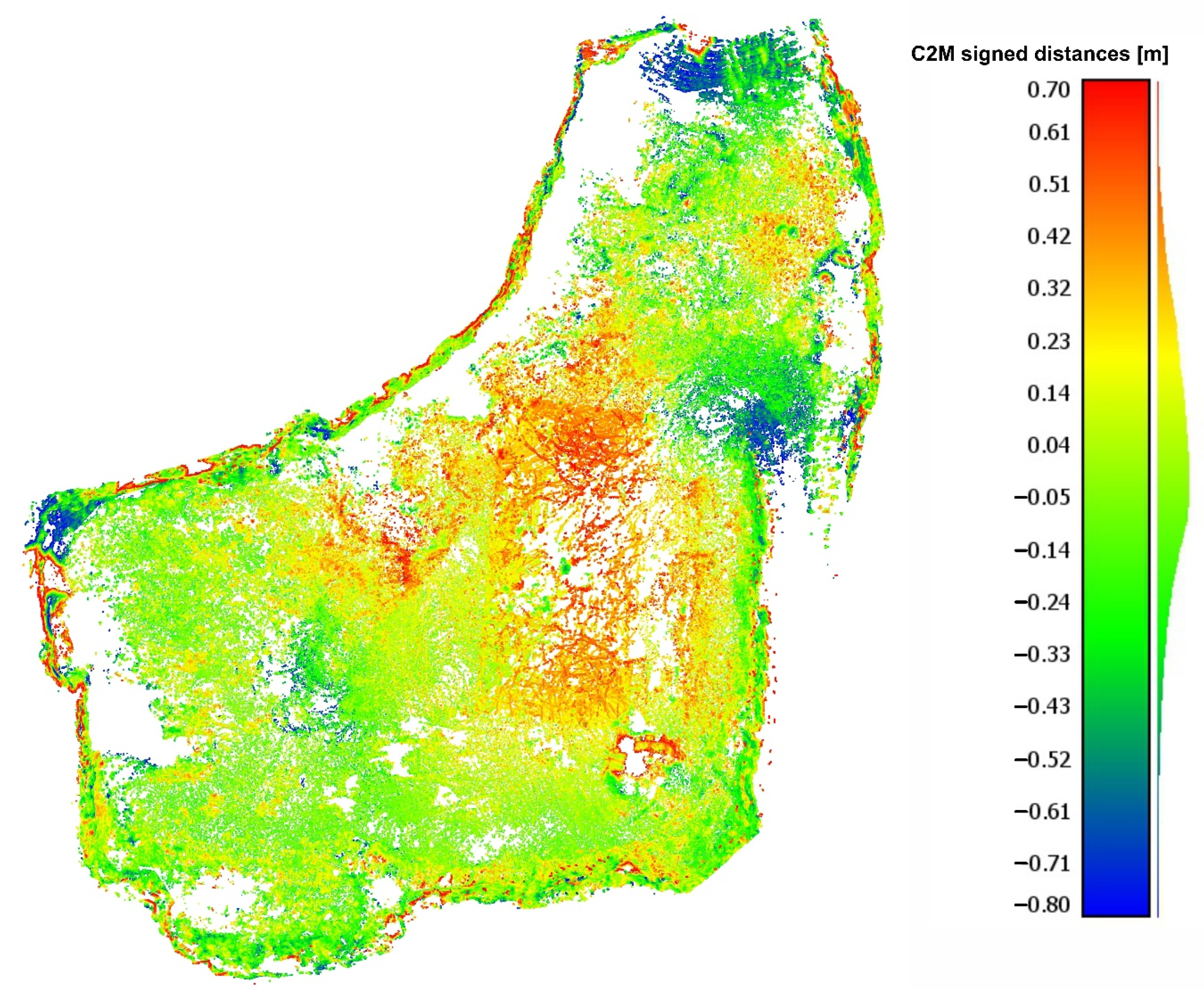
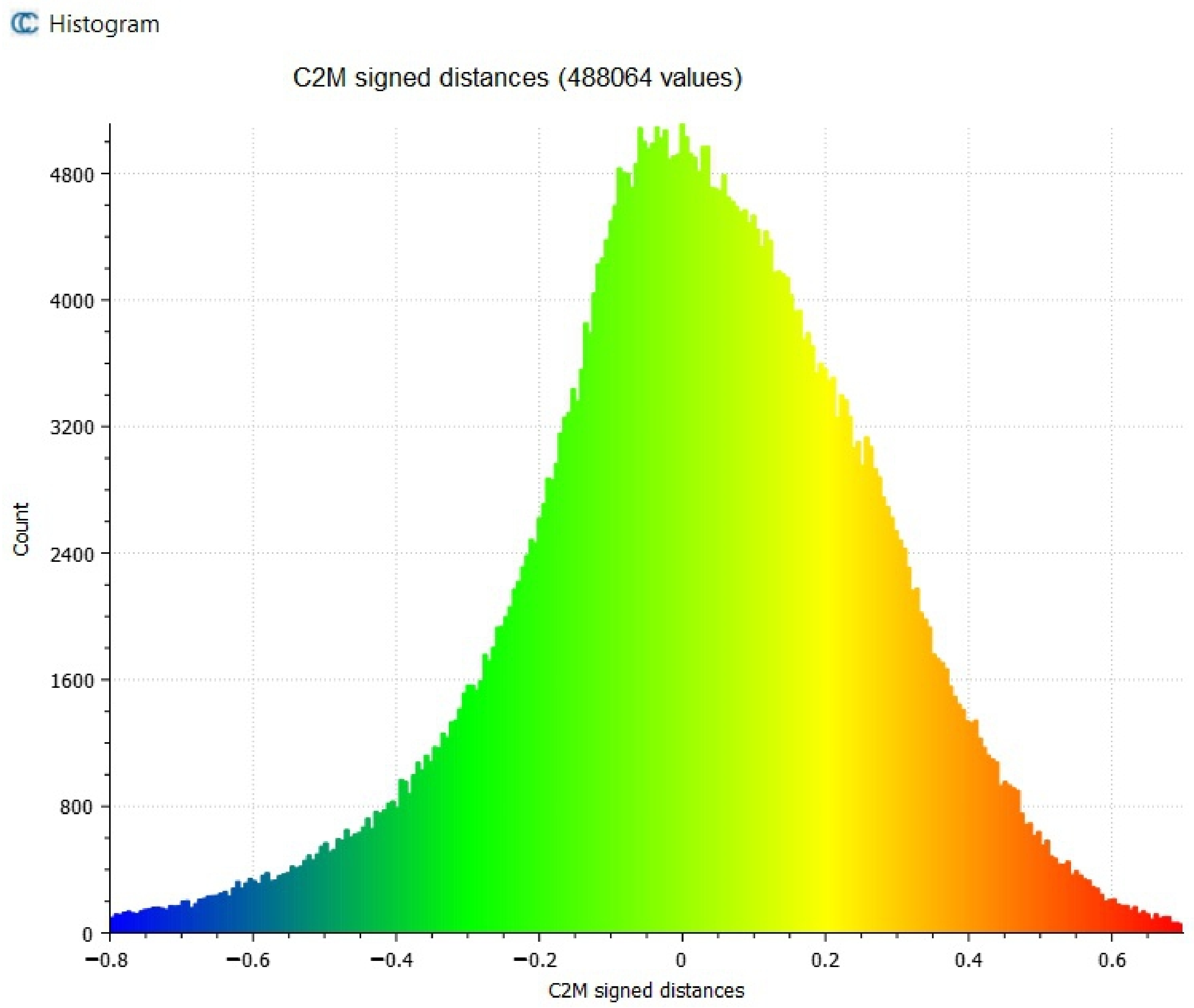
Figure 9 shows the spatial distribution of the distances between the points in the SLAM-based cloud, while
Figure 10 is their histogram. A more detailed analysis of the locations with the highest individual deviations between the models leads to a conclusion that they occur in areas not covered by the MLS scanning or on areas covered with scattered greenery. In practical applications typical of an active open-pit mine, both cases should not affect the quality of the obtained geometrical data. The obtained accuracy levels (the distance between SLAM point cloud—MLS delivered mesh model is at a level of ±5 cm) is sufficient to calculate volumes in open-pit mines of similar scale and to update their 3D models, since the geometry changes associated with the periodically monitored advances of the mining operation would usually be in the order of meters.
LiDAR observations in the implemented MLS approach allow the angles and distances to be measured from multiple measurement stations represented by the trajectory of the vehicle movement. In comparison to a classic approach to LiDAR measurements, TLS offers a possibility to record a continuous surface in a DSM and to reconstruct it closely representing the 3D surface with high measurement resolution. Importantly, in both the classic TLS approach and the MLS, the measuring instrument has an identical incidence angle at the analyzed object.
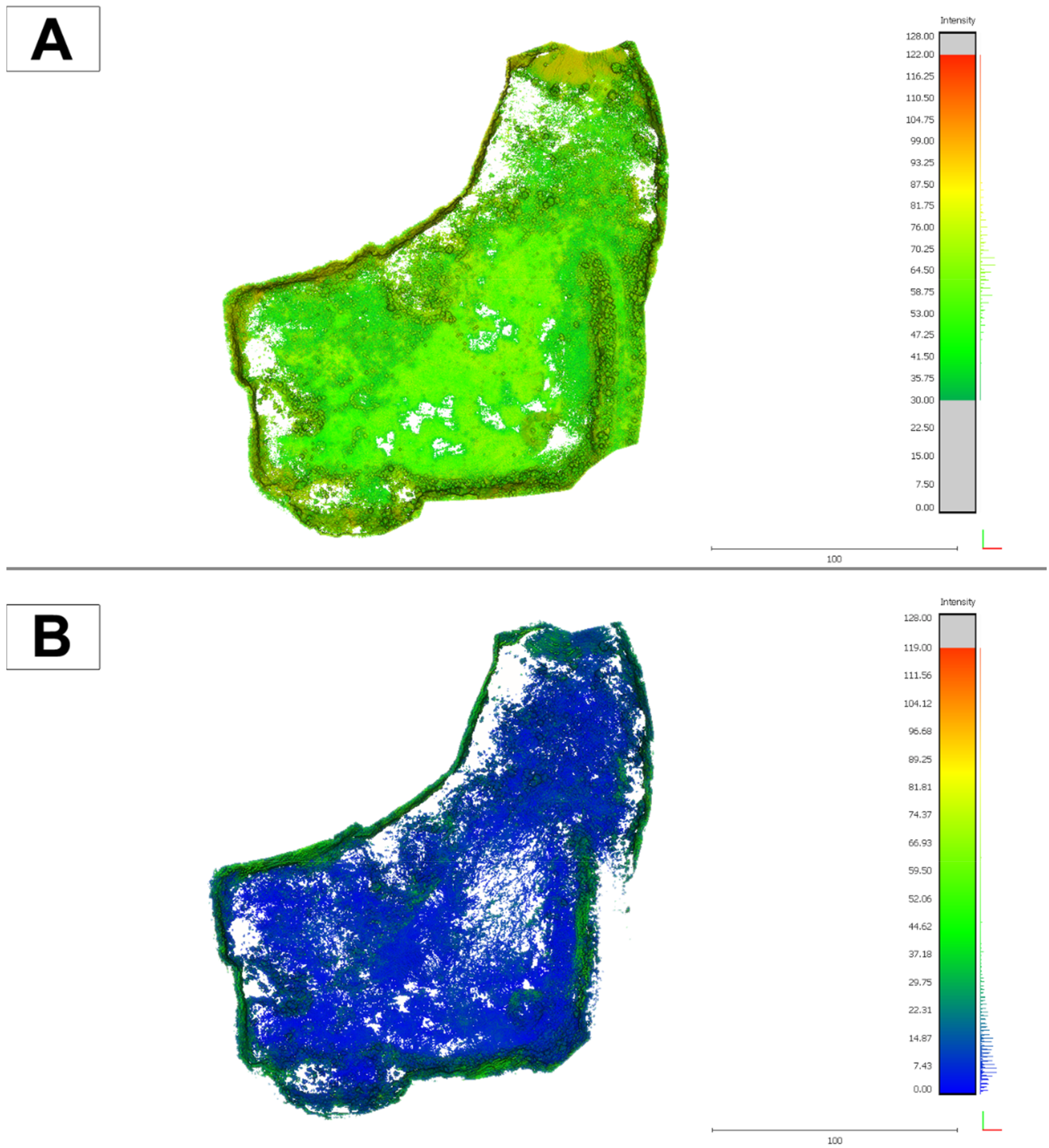
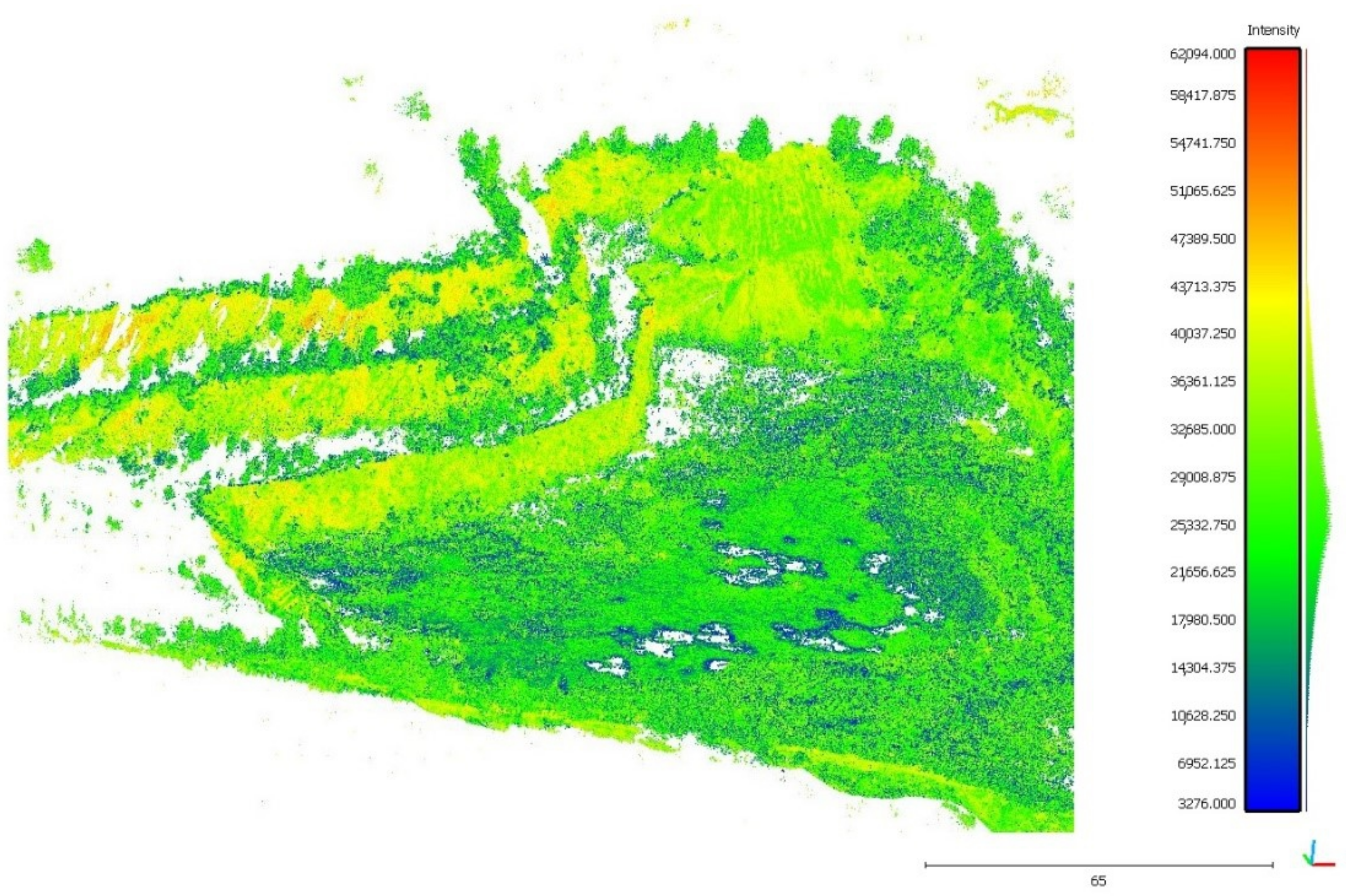
The LiDAR MLS method is seemingly limited by the impossibility to acquire data from objects which are covered with water. The observed gaps in the data are due to the absorption of the active LiDAR beam by the air-water medium, which causes the laser beam to become deflected and the LiDAR measurement point not to be recorded (white empty pixels in
Figure 11). Another limitation of the LiDAR methods lies in the so-called shadows cast by objects which obstruct the laser beam. The above limitations are minimized by implementing the MLS technique, which allows a continuous measurement along an MLS trajectory.
5. Conclusions
Mobile laser scanning technology is experiencing a dynamic growth in surveying. This growth is observed in the precision of the measurements, in the amounts of obtained data (scanning resolution and speed), and in the number of the transport platforms being employed.
The in-field tests performed in the Mikoszów granite mine employed two types of laser scanning systems to demonstrate their usefulness and the potential of using the results in the modeling and monitoring of the geometry changes in an open-pit excavation. The novelty of the presented solution lies in the integration of spatial data acquired with sensors that vary in accuracy, measurement platform and procedure and data processing to optimize the effort and cost of maintaining a time-varying 3D mine model.
The solution proposed by the authors is based on performing the first scan with the use of a precise Riegl VMZ 400i system—this is indicated as state (point cloud) T0. The most significant advantages of the method include the measurement range, data acquisition speed and the quality of the MLS trajectory adjustment, which allows precision in the order of single centimeters. Moreover, our method does not require the use of ground control points in the measurement area or outside of it. The results of the bundle adjustment of the MLS measurements were similar to the accuracy of RTK GNSS.
Data obtained with the use of this method may be successfully used in 3D modeling the geometry of an excavation, or in planning or monitoring the progress of mining operations, with respect to both compact rock (such as granite in this case, which may be mined in the form of both blocks and aggregate), and bulk minerals.
Consecutive measurement sessions are performed at times T1 − … − Tn with the use of Velodyne VLP-16, which is a tool operated in the SLAM approach. The experiment, which consisted of acquiring data and then in combining the acquired data into a local point cloud and in georeferencing the data into an MLS cloud, demonstrated that the data are fitted at a precision sufficient to use them in the modeling of the advancement of mining works. From the perspective of mining-related surveying, the data are of adequate quality. Also, the solution proves economical, as it is based on the Velodyne VLP-16 low-cost approach. Importantly, a scanner of this type does not need a highly skilled operator. Additionally, the procedure of data processing and visualization is partially automated (on the basis of low-cost and open-access software solutions), which is a factor limiting the cost related to buying the software and employing a trained operator.
A novel procedure of carrying out 3D measurements was developed that can be applied to the entire life cycle of an open-pit mine. The experiment was successfully carried out to test it in the real mining environment. The core element of the proposed procedure is the creation of a base mine model with a precise MLS platform. Subsequent stages of work, i.e., periodic measurement sessions with a SLAM-based system, are utilized to update the base model and perform calculations of the excavated volume. It is worth noting that the advantage of using Velodyne VLP-16 or similar lidar in the SLAM solution is that there is no need for a highly skilled operator, costly equipment, or software. Such low-cost solution could enable employing digital twin concepts in the small mining companies, e.g., quarries.
Another advantage of the proposed solution is the lack of need to establish the ground control points. The base model is georeferenced using simultaneous GNSS RTK measurements and the subsequent SLAM models are registered to it in cloud-to-cloud manner, since the majority of the mine model is stable over time.
The authors would especially like to emphasize that the results of the experiment performed in the Mikoszów open-pit mine clearly indicate that the integration of the MLS LiDAR technique and of the handheld SLAM LiDAR technique according to the method here described allows a 3D model of the excavation to be constructed and updated in real time. The resultant high-resolution point cloud allows the designing, inventorying, and feeding of big data databases in mines, according to the idea of Industry 4.0. LiDAR techniques used in the analyzed mine enable a fast and comfortable acquisition of 3D information about the excavation over the life cycle of a mine. This information may be used at every stage of the mining operations in open-pit mines, including in prospecting and exploration works, in access and development works, in the exploitation of the mineral, in the reclamation works, and in the management of the post-mining area.
Author Contributions
Conceptualization, J.G.-Z., J.W. and D.K.; methodology, J.W. and P.T.; software, P.T. and J.W.; validation, J.W. and P.T.; formal analysis, J.W. and P.T.; investigation, J.W. and P.T.; resources, J.G.-Z. and J.K.-K.; data curation, J.G.-Z. and J.K.-K.; writing—original draft preparation, J.W., P.T., J.G.-Z., J.K.-K. and D.K.; writing—review and editing, J.W., P.T., J.G.-Z., J.K.-K. and D.K.; visualization, J.W. and P.T.; supervision, J.G.-Z. and J.K.-K.; project administration, J.G.-Z., J.K.-K. and D.K. All authors have read and agreed to the published version of the manuscript.
Funding
This research received no external funding.
Institutional Review Board Statement
Not applicable.
Informed Consent Statement
Not applicable.
Data Availability Statement
The data presented in this study are available on request from the corresponding author.
Acknowledgments
Authors would like to thank Mineral Polska Ltd and the mining plant operations manager, Mirosław Mróz, for the opportunity to perform measurements session in the Mikoszów open-pit mine.
Conflicts of Interest
The authors declare no conflict of interest.
References
- Battulwar, R.; Winkelmaier, G.; Valencia, J.; Naghadehi, M.Z.; Peik, B.; Abbasi, B.; Parvin, B.; Sattarvand, J. A Practical Methodology for Generating High-Resolution 3D Models of Open-Pit Slopes Using UAVs: Flight Path Planning and Optimization. Remote Sens. 2020, 12, 2283. [Google Scholar] [CrossRef]
- Nieto, J.I.; Monteiro, S.T.; Viejo, D. 3D geological modelling using laser and hyperspectral data. In Proceedings of the 2010 IEEE International Geoscience and Remote Sensing Symposium, Honolulu, HI, USA, 25–30 July 2010. [Google Scholar] [CrossRef]
- Werner, T.; Bebbington, A.; Gregory, G. Assessing impacts of mining: Recent contributions from GIS and remote sensing. Extr. Ind. Soc. 2019, 6, 993–1012. [Google Scholar] [CrossRef]
- Deliormanli, A.H.; Maerz, N.H.; Otoo, J. Using terrestrial 3D laser scanning and optical methods to determine orientations of discontinuities at a granite quarry. Int. J. Rock Mech. Min. Sci. 2014, 66, 41–48. [Google Scholar] [CrossRef]
- Buckley, S.J.; Howell, J.; Enge, H.; Kurz, T. Terrestrial laser scanning in geology: Data acquisition, processing and accuracy considerations. J. Geol. Soc. 2008, 165, 625–638. [Google Scholar] [CrossRef]
- Shahbazi, M.; Sohn, G.; Théau, J.; Menard, P. Development and Evaluation of a UAV-Photogrammetry System for Precise 3D Environmental Modeling. Sensors 2015, 15, 27493–27524. [Google Scholar] [CrossRef] [PubMed] [Green Version]
- Keawaram, B.; Dumrongchai, P. Comparisons of Surveying with Terrestrial Laser Scanner and Total Station for Volume Determination of Overburden and Coal Excavations in Large Open-Pit Mine. World Acad. Sci. Eng. Technol. Int. J. Geol. Environ. Eng. 2017, 11, 964–972. [Google Scholar]
- Zaky, K.; Ghonem, A.; El Semary, H. Accuracy, time and cost of different leveling types. Eng. Res. J. 2002, 79, 55–67. [Google Scholar]
- Can, E.; Mekik, Ç.; Kusçu, ̧S. Akçın, H. Computation of subsidence parameters resulting from layer movements post-operations of underground mining. J. Struct. Geol. 2013, 47, 16–24. [Google Scholar] [CrossRef]
- Brown, N.; Kaloustian, S.; Roeckle, M. Monitoring of open pit mines using combined GNSS satellite receivers and robotic total stations. In Proceedings of the 2007 International Symposium on Rock Slope Stability in Open Pit Mining and Civil Engineering, Perth, Australia, 12–14 September 2007; Australian Centre for Geomechanics: Crawley, Australia, 2007; pp. 417–429. [Google Scholar]
- Einicke, G.; Martin, S.; von Voithenberg, M.V.; Enderle, W. Pseudolite Options for Improved Mining Navigation. In Proceedings of the International Global Navigation Satellite Systems Society IGNSS Symposium 2006, Holiday Inn Surfers Paradise, Gold Coast, QL, Australia, 17–21 July 2006. [Google Scholar]
- McHugh, E.L.; Dwyer, J.; Long, D.G.; Sabine, C. Applications of Ground-Based Radar to Mine Slope Monitoring; Report of Investigations 9666; NIOSH-Publications Dissemination: Cincinnati, OH, USA, 2006. [Google Scholar]
- Wajs, J. Research on surveying technology applied for DTM modelling and volume computation in open pit mines. Min. Sci. 2015, 22, 75–83. [Google Scholar] [CrossRef]
- Xu, Z.; Xu, E.; Wu, L.; Liu, S.; Mao, Y. Registration of Terrestrial Laser Scanning Surveys Using Terrain-Invariant Regions for Measuring Exploitative Volumes over Open-Pit Mines. Remote Sens. 2019, 11, 606. [Google Scholar] [CrossRef] [Green Version]
- Tong, X.; Liu, X.; Chen, P.; Liu, S.; Luan, K.; Li, L.; Liu, S.; Liu, X.; Xie, H.; Jin, Y.; et al. Integration of UAV-Based Photogrammetry and Terrestrial Laser Scanning for the Three-Dimensional Mapping and Monitoring of Open-Pit Mine Areas. Remote Sens. 2015, 7, 6635–6662. [Google Scholar] [CrossRef] [Green Version]
- Jozkow, G.; Totha, C.; Grejner-Brzezinska, D. UAS topographic mapping with Velodyne LiDAR sensor. ISPRS Ann. Photogramm. Remote Sens. Spat. Inf. Sci. 2016, 3, 201–208. [Google Scholar] [CrossRef] [Green Version]
- Toth, C.; Jozkow, G.; Grejner-Brzezinska, D. Mapping with Small UAS: A Point Cloud Accuracy Assessment. J. Appl. Geod. 2015, 9, 213–226. [Google Scholar] [CrossRef]
- Jaboyedoff, M.; Abellán, A.; Carrea, D.; Derron, M.H.; Matasci, B.; Michoud, C. Mapping and monitoring of landslides using LiDAR. In Natural Hazards; CRC Press: Boca Raton, FL, USA, 2018; pp. 397–420. [Google Scholar]
- Kukko, A.; Kaartinen, H.; Hyyppä, J.; Chen, Y. Multiplatform Mobile Laser Scanning: Usability and Performance. Sensors 2012, 12, 11712–11733. [Google Scholar] [CrossRef] [Green Version]
- Okhotin, A.L. Application of Laser scanning in mine surveying. Proc. FIG Comm. 2009, 6, 53–62. [Google Scholar]
- Bertayeva, K.; Panaedova, G.; Natocheeva, N.; Belyanchikova, T. Industry 4.0 in the mining industry: Global trends and innovative development. In E3S Web of Conferences; EDP Sciences: Les Ulis, France, 2019; Volume 135, p. 04026. [Google Scholar]
- Lööw, J.; Abrahamsson, L.; Johansson, J. Mining 4.0—The Impact of New Technology from a Work Place Perspective. Min. Metall. Explor. 2019, 36, 701–707. [Google Scholar] [CrossRef] [Green Version]
- Gackowiec, P.; Podobińska-Staniec, M.; Brzychczy, E.; Kühlbach, C.; Özver, T. Review of Key Performance Indicators for Process Monitoring in the Mining Industry. Energies 2020, 13, 5169. [Google Scholar] [CrossRef]
- Sukiennik, M. Challenges Faced by Businesses in the Mining Industry in the Context of the Industry 4.0 Philosophy. Multidiscip. Asp. Prod. Eng. 2018, 1, 621–626. [Google Scholar] [CrossRef]
- Sishi, M.N.; Telukdarie, A. Implementation of industry 4.0 technologies in the mining industry: A case study. In Proceedings of the 2017 IEEE International Conference on Industrial Engineering and Engineering Management (IEEM), Singapore, 10–13 December 2017. [Google Scholar] [CrossRef]
- Gruszecki, J. (Geological Company Proxima S.A., Wroclaw, Poland). Geological documentation of the granite and gneiss deposit in category C1 Mikoszow in Strzelin, province. Wroclaw. Unpublished work. 1993. [Google Scholar]
- Kominowski, K. (A-Z Geometr s.c., Walbrzych, Poland). Geological documentation of the Mikoszow granite and gneiss deposit in cat. C1, places Mikoszow, commune and over Strzelin, voivodeship Lower Silesia. Unpublished work. 2001. [Google Scholar]
- Majkowska, U. (Majkowska Geological Services, Wroclaw, Poland). Appendix No. 1 to the geological documentation of the Mikoszow granite and gneiss deposit in cat. C1 in Strzelin, Strzelin commune, province Wroclaw. Unpublished work. 1996. [Google Scholar]
- Szkudlarek, L.; Bernatowicz, W.; Ryng-Duczmal, W.; Bernatowicz, M.; Koltowska, M.; Gil, R.; Filipowska, I. Renewal of the Mining License for the Mikoszow Deposit; Environmental Impact Report; Ekovert Szkudlarek: Wroclaw, Poland, 2017. [Google Scholar]
- Adán, A.; Quintana, B.; Prieto, S. Autonomous Mobile Scanning Systems for the Digitization of Buildings: A Review. Remote Sens. 2019, 11, 306. [Google Scholar] [CrossRef] [Green Version]
- Hussnain, Z.; Elberink, S.O.; Vosselman, G. Enhanced trajectory estimation of mobile laser scanners using aerial images. ISPRS J. Photogramm. Remote Sens. 2021, 173, 66–78. [Google Scholar] [CrossRef]
- Singh, S.K.; Raval, S.; Banerjee, B.P. Automated structural discontinuity mapping in a rock face occluded by vegetation using mobile laser scanning. Eng. Geol. 2021, 285, 106040. [Google Scholar] [CrossRef]
- Riegl Hybrid Mobile Laser Scanning System Brochure. Available online: http://www.riegl.com/uploads/tx_pxpriegldownloads/RIEGL_VMZ_at-a-glance_brochure_2018-11-28.pdf (accessed on 26 January 2021).
- Chang, L.; Niu, X.; Liu, T.; Tang, J.; Qian, C. GNSS/INS/LiDAR-SLAM Integrated Navigation System Based on Graph Optimization. Remote Sens. 2019, 11, 1009. [Google Scholar] [CrossRef] [Green Version]
- Hening, S.; Ippolito, C.A.; Krishnakumar, K.S.; Stepanyan, V.; Teodorescu, M. 3D LiDAR SLAM Integration with GPS/INS for UAVs in Urban GPS-Degraded Environments; AIAA Information Systems-AIAA Infotech@Aerospace; American Institute of Aeronautics and Astronautics: Reston, VA, USA, 2017. [Google Scholar] [CrossRef] [Green Version]
- Karam, S.; Lehtola, V.; Vosselman, G. Strategies to integrate imu and lidar slam for indoor mapping. ISPRS Annals of the Photogrammetry. Remote Sens. Spat. Inf. Sci. 2020, 1, 223–230. [Google Scholar] [CrossRef]
- Sadruddin, H.; Mahmoud, A.; Atia, M.M. Enhancing Body-Mounted LiDAR SLAM using an IMU-based Pedestrian Dead Reckoning (PDR) Model. In Proceedings of the 2020 IEEE 63rd International Midwest Symposium on Circuits and Systems (MWSCAS), Springfield, MA, USA, 9–12 August 2020. [Google Scholar] [CrossRef]
- Quan, M.; Piao, S.; Tan, M.; Huang, S.S. Tightly-Coupled Monocular Visual-Odometric SLAM Using Wheels and a MEMS Gyroscope. IEEE Access 2019, 7, 97374–97389. [Google Scholar] [CrossRef]
- Brossard, M.; Bonnabel, S.; Barrau, A. Invariant Kalman Filtering for Visual Inertial SLAM. In Proceedings of the 2018 IEEE 21st International Conference on Information Fusion (FUSION), Cambridge, UK, 10–13 July 2018. [Google Scholar] [CrossRef] [Green Version]
- Mendes, E.; Koch, P.; Lacroix, S. ICP-based pose-graph SLAM. In Proceedings of the 2016 IEEE International Symposium on Safety, Security, and Rescue Robotics (SSRR), Lausanne, Switzerland, 23–27 October 2016. [Google Scholar] [CrossRef] [Green Version]
- Pierzchała, M.; Giguère, P.; Astrup, R. Mapping forests using an unmanned ground vehicle with 3D LiDAR and graph-SLAM. Comput. Electron. Agric. 2018, 145, 217–225. [Google Scholar] [CrossRef]
- Muglikar, M.; Zhang, Z.; Scaramuzza, D. Voxel Map for Visual SLAM. In Proceedings of the 2020 IEEE International Conference on Robotics and Automation (ICRA), Paris, France, 31 May–31 August 2020. [Google Scholar] [CrossRef]
- Guclu, O.; Can, A.B. Fast and Effective Loop Closure Detection to Improve SLAM Performance. J. Intell. Robot. Syst. 2017, 93, 495–517. [Google Scholar] [CrossRef]
- Sammartano, G.; Spanò, A. Point clouds by SLAM-based mobile mapping systems: Accuracy and geometric content validation in multisensor survey and stand-alone acquisition. Appl. Geomat. 2018, 10, 317–339. [Google Scholar] [CrossRef]
- Ren, Z.; Wang, L.; Bi, L. Robust GICP-Based 3D LiDAR SLAM for Underground Mining Environment. Sensors 2019, 19, 2915. [Google Scholar] [CrossRef] [PubMed] [Green Version]
- Zhang, J.; Singh, S. Low-drift and real-time lidar odometry and mapping. Auton. Robot. 2016, 41, 401–416. [Google Scholar] [CrossRef]
- Shan, T.; Englot, B. LeGO-LOAM: Lightweight and Ground-Optimized Lidar Odometry and Mapping on Variable Terrain. In Proceedings of the 2018 IEEE/RSJ International Conference on Intelligent Robots and Systems (IROS), Madrid, Spain, 1–5 October 2018. [Google Scholar] [CrossRef]
- Nelson, E. Blam—Berkeley Localization and Mapping. Available online: https://github.com/erik-nelson/blam (accessed on 26 January 2021).
- Vassena, G.; Clerici, A. Open pit mine 3d mapping by tls and digital photogrammetry: 3d model update thanks to a slam based approach. Int. Arch. Photogramm. Remote Sens. Spat. Inf. Sci. 2018, 42, 1145–1148. [Google Scholar] [CrossRef] [Green Version]
- Koide, K.; Miura, J.; Menegatti, E. A portable three-dimensional LIDAR-based system for long-term and wide-area people behaviour measurement. Int. J. Adv. Robot. Syst. 2019, 16, 172988141984153. [Google Scholar] [CrossRef]
- Quigley, M.; Conley, K.; Gerkey, B.; Faust, J.; Foote, T.; Leibs, J.; Bergerm, E.; Wheeler, R.; Ng, A.Y. ROS: An open-source Robot Operating System; ICRA: Kobe, Japan, 2009; Volume 3, p. 5. [Google Scholar]
| Publisher’s Note: MDPI stays neutral with regard to jurisdictional claims in published maps and institutional affiliations. |
© 2021 by the authors. Licensee MDPI, Basel, Switzerland. This article is an open access article distributed under the terms and conditions of the Creative Commons Attribution (CC BY) license (https://creativecommons.org/licenses/by/4.0/).


 ,
, 


