
A Novel Low Voltage Selective Circuit Breaker with Additional Current Path


1
Department of Electrical Engineering, Cracow University of Technology, 31-155 Cracow, Poland
2
Department of Energy, Cracow University of Technology, 31-864 Cracow, Poland
*
Author to whom correspondence should be addressed.
Energies 2021, 14(23), 8179; https://0-doi-org.brum.beds.ac.uk/10.3390/en14238179
Submission received: 13 October 2021
/
Revised: 23 November 2021
/
Accepted: 1 December 2021
/
Published: 6 December 2021
Abstract
:The subject of the article is a description of the operating principle of the new proposal of the selective circuit breaker, which is an extension of the existing selective devices. The solution proposed in the article allows one to increase the selectivity range of classic selective circuit breakers. In the case of networks with high values of short-circuit loop impedance, operating at reduced supply voltage, the proposed solution will not limit the short-circuit current too excessively as it is in the case of classic solutions. This advantage will allow for the correct reaction of the protections preceding them. The article presents the structure and analysis of the selection of parameters of the proposed solution. The results of simulation calculations have also been illustrated.
1. Introduction
Electricity, apart from the obvious advantages associated with its use, which facilitate everyday life, must guarantee the safety of its users as well as the certainty and reliability of its supply. The commonness of using electrical energy and as a consequence, operating electrical equipment by untrained people results as a requirement of ensuring fast and effective working of the protection devices in installation damage cases. The most common protection against short-circuits are miniature circuit breakers (MCB), fuses, and selective circuit breakers (SCB). The right project and implementation of the electrical installations allow us to realize the condition of ensuring off-switching of the faulted circuit while maintaining coordination between protection devices [1,2].
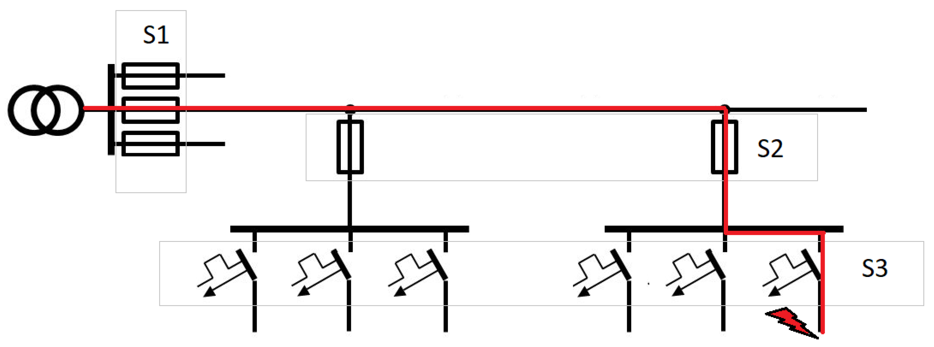
The coordination between protection devices means such working of the protection apparatus that in case of short-circuit there comes next circuit opening by the closest apparatus to the place of failure. Based on Figure 1, a short circuit occurs at the end of the circuit protected by the S3 protection. In such a situation, the short-circuit current flows successively through the S1, S2, and S3 protections. In this case, selectivity depends on such a combination of the S1, S2, and S3 protections that the fault current causes only the activation of the S3 protection, located closest to the fault location, without triggering the S2 and S1 protections. Due to it, the rest of the electrical installation is working properly and supplies the other devices. In the case of non-selectivity, there can act the main breaker and switch off all circuits after it. Therefore the case of maintaining selectivity in electrical installation is so important [3,4].
Over the years, many different protection devices were invented that improved the possibility of selectivity maintenance and also came into being special rules of the protection apparatus right selection in the electrical installations. Examples of the apparatus constructions are available in patents [5,6,7].
Existing on the market SCBs are working properly in cases of rated voltage level in the protected circuit, but there can occur some problems (with coordination of protections) when the voltage decreases to 90% rated voltage or even more. These cases are not commonly taken into consideration, which causes a gap in worldwide research.
The character of the short-circuit current is dependent on the energy source type, fault localization, fault type. Therefore there can be highlighted short-circuits close and far from the generator. In case of supplying low voltage installation from the grid, there is considered only far from the generator type. However, that situation is different for local energy sources like backup synchronous generator sets, which are used to ensure electricity when there is no voltage from the grid. That situation changes the short-circuit source parameters and may lead to serious problems with guarantying required protection safety. In reference [8] is described the 3-phase short-circuit character while the installation is fed from the low voltage low power synchronous generator. This problem is considered in [9], where MCBs and SCBs are tested during controlled short-circuits supplied from the low power synchronous generator. Conclusions from this research are convergent with the other publication [10]: Classical apparatus does not guarantee reliable work in hybrid installations or supplied from local energy sources. The MCB’s tripping is also considered in [11]. Backup sources, small wind turbines using axial flux permanent magnet generator (AFPMG) [12,13], or small hydropower plants [14] are much less stiff in voltage profile analysis compared to the grid supply. This causes bigger voltage fluctuations dependently on the connected loads and frequently starting. High voltage drops can occur, which are even greater than 10% during supply from the grid. That situation is possible especially in the rural areas, where the overhead lines are long, so the longitudinal impedance is high, and there are installed relatively high power loads, e.g., induction motors. When they are directly started, the current is high what causes high voltage drops in the line. Mentioned examples are chosen to show the problem with ensuring fast and proper working of protective devices during short-circuits and also to guarantee their selective cooperation in building installations.
In relation to the above argument, the novelty of the proposed solution is that the use of the proposed SCB compared to existing solutions guarantees the extension of selectivity range in case of significant voltage drop in the installation, which is not retained for existing solutions. This is also the main disadvantage of the currently used SCB. In low voltage installations (e.g., Un = 230 V), where is a possibility of significant voltage drops (all previously mentioned supply types), the SCB device does not ensure selectivity. The short-circuit circuit, due to the reduced voltage, is excessively limited by the usually installed SCBs, and causes incorrect and not enough quick activation of the following protection.
The novel SCB can be used for the same rages of currents and voltages as the existing SCB. In currently used SCB for different values of current, must have one additional resistor, while in proposed novel SCB two resistors must be determined. This little modification allows us to significantly increase the values of short-circuit current and to ensure proper selectivity. This advantage/feature is really important for the electrical installations designers because it influences the significant simplification of the designing and selecting process of circuit breakers in low voltage installations. It should be underlined, that the proposed SCB consists of the same elements, which are used in classical SCBs or MCBs. Therefore, in this manuscript, the switching times of different rated currents of the apparatus contactors are not analyzed. In [15,16], laboratory measurements of low voltage contactor switching times are presented. In relation to the proposed SCB, neither the switching times of contactors analysis nor application of additional electronic controller to switching operation are not required.
In the literature, the selective coordination between the protective apparatus is analyzed, e.g., in [17], where circuit breakers’ time-current curves are investigated according to the 2005 National Electrical Code. Some solutions of the low-voltage circuit breakers coordination are built with the use of digital circuits [18]. However, in such solutions, always is the basic problem with the high costs of the proposed devices. In low voltage electrical installations the most important issue (i) is to ensure the safety of electricity use, but the second factor (ii) is connected with investment costs, which should be as low as it is possible to fulfill the first condition (i).
However, in practical applications of the selectivity theory, the electrical installation designers mostly use time-current curves and in some cases have problems with the appropriate selection of the protective apparatus based on the classical SCB constructions and commonly used other equipment as fuses or MCBs. Or even well-designed installation may not work reliably because of mentioned before unstable supplying voltage profile. The proposed novel solution significantly improves the selectivity coordination range between protection devices.
The major contributions of this paper are:
- -
- showing the problem with proper coordination in low voltage installations operating with dropped supply voltage,
- -
- presentation a novel SCB construction,
- -
- advantages of using a novel SCB in installations and protections coordination with variable and lowered supply voltage during short-circuits.
In this paper, there are described coordination types of protective devices in Section 2. Then in Section 3 are presented basic working rules of typically used worldwide SCB. The next section is about the novel SCB construction and operating principles. In Section 5 authors show research results and in the next one are described conclusions.
2. Protection Coordination Types
There can be highlighted different types of coordination between protections in electrical networks described by MCB’s manufacturer [19,20]:
- current selectivity coordination,
- time selectivity coordination,
- logic selectivity coordination,
The first-mentioned type is connected with setting different current values on the protections because of different short-circuit current values in places of their installation in the system resulting from different impedance loop values. Usually, between two instantaneous working protective devices is a relatively high-impedance element (the impedance of the electrical circuit that connects two considered protective devices) and due to it, there is the possibility to grade the short-circuit current values. This is the most commonly used method to achieve selectivity.
In circuit configurations, where between subsequent circuit breakers, the impedance loop/distance is relatively low, and in consequence short circuit currents values are similar, the time selectivity coordination is used. The time coordination means such chosen installation protective devices, that have intentionally implemented delay times of each apparatus for the same short-circuit current values. In this way, the possibility of fast reaction by the closest protective device to the place of failure in a set time should occur. To increase the reliability of selectivity coordination two previously mentioned methods can be used together. However, in the case of hybrid coordination (time and current coordination), one must take into account the extended response time of the device and thus a longer thermal and dynamic effect of the short-circuit process on the protected circuit.
If a specific sequence of protection operations is required, not necessarily dictated by the gradation of the short-circuit current value the logic coordination is used. The logic coordination is available in installed devices that are connected together with the control unit and in case of any short-circuit reactions are chosen according to the strategy implemented in the electric system. This type of coordination can be used also in the typical configuration of circuit breakers to ensure selectivity, however, the costs of applying this method are definitely higher than in the case of current or time selectivity coordination. Additionally, the delays related to the need to communicate between devices affect their longer response times.
Considering energy coordination there are compared energies necessary to work of given protection. In this article, the focus will be on protective devices working with the current coordination–adjustable current coordination.
3. The Selective Circuit Breakers and Short-Circuit Off-Switching
There are different constructions of the SCB, the differences result from the order in patent protection, necessity of the apparatus development, and production companies. The common feature of all SCB solutions is short-circuited current value reduction to usually about five times rated SCB current and impossibility to turn on the SCB while the short-circuit is still in the protected circuit. These two features are typically realized by the additional current path with increasing impedance and continuous phase voltage measurement, respectively. Figure 2 presents the electrical scheme of one of the typical SCB construction solutions.
To switch on the apparatus, thereafter raising the lever to ON position, there are closed K2 and K3 contacts, and the installation is supplied by the additional current path consisting of bi-metal B2, limiting resistor R0, and contact K2. At the same time, there is measured phase voltage by under-voltage relay E and in case of occurring short circuit, there cannot be switched on the SCB. If there is no fault in the installation, there is closed the contact K1 and then the main current path conducts electrical current. When the SCB is switched on and then there appears short-circuit, the electromagnetic element Z switches off the K1 conduct and then the fault is supplied by the additional current path and the short-circuit current value is limited by selected resistor R0 to the proper value which allows to switch off the fault by the next and closer protection device. If there is no action in the circuit, the bi-metal B2 heats up and finally switches off the installation.
In low voltage installations fed from the mains, there can be highlighted two components of the short-circuit current [1,3]:
- Steady-state component expressed as
- DC component expressed as
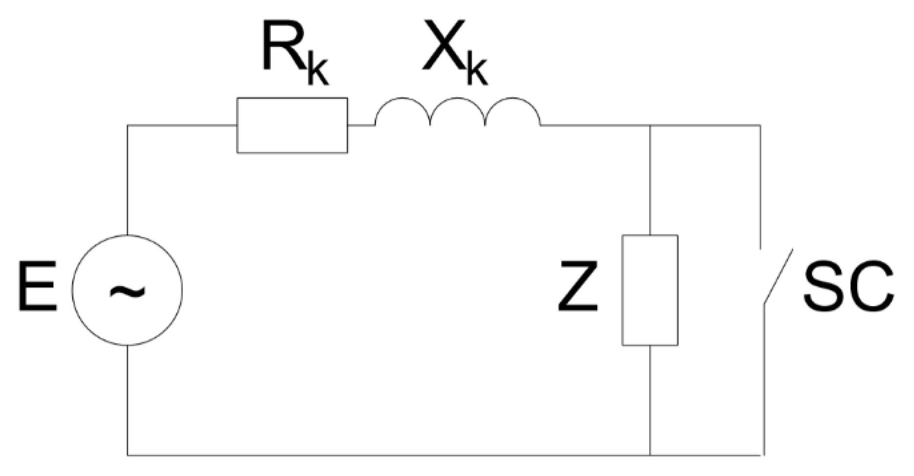
A circuit equivalent of short-circuit loop is presented in Figure 3.
According to Formulas (1) and (2), there is a visible influence of the voltage on the short-circuit current value. In many cases, the electrical networks experience voltage drops as a consequence of, for example, cage induction motors starting without soft starts, high transmission of the inductive reactive power in the supply network, or overload of the local low voltage transmission lines. Therefore, the short-circuit conditions may change what can lead to the ineffective working of the electrical installation protection apparatus. The maximal reaction times of the protection devices are described in the regulations [21]. For example, in the TN systems, there are different values of the maximal permissible time of fault duration, which are shown in Table 1 [21].
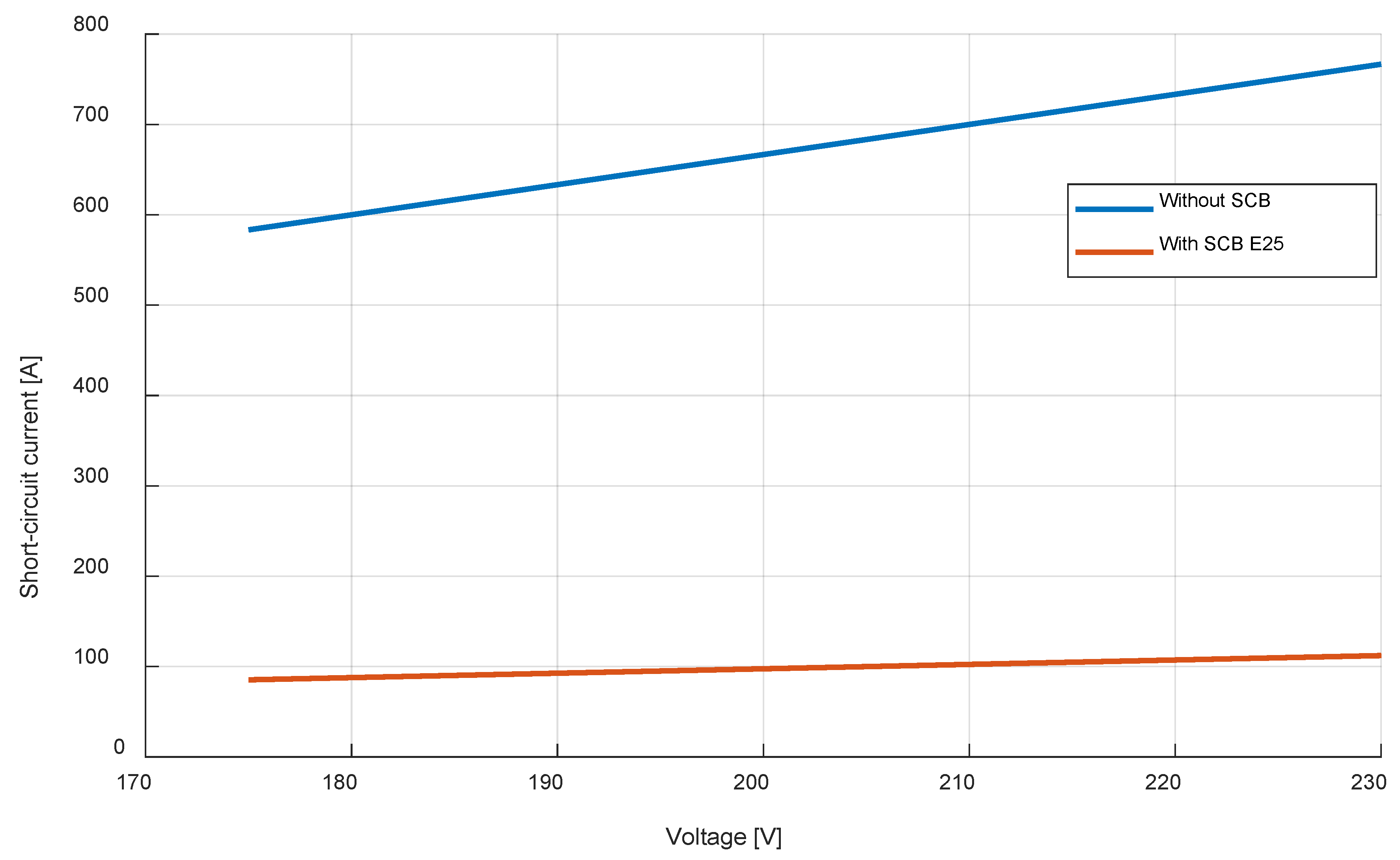
The impact of the voltage value on the short-circuit current value was calculated for short-circuit impedance loop Z = 0.354 Ω and with SCB limiting resistor RO = 1.75 Ω and voltages range from 185 V to 253 V and presented in Figure 4.
As it is shown in Figure 4, for rated voltage expected current value is 650 A, while for 110% of rated voltage this value increases to 715 A. When voltage is lower (185 V) the value is expected as 523 A. In the case of using SCB, the current values are limited to
- 92 A with 185 V supply voltage,
- 114 A with 230 V supply voltage,
- 125 A with 253 V supply voltage.
Calculated values show a big difference in expected short-circuit currents when the supply voltage conditions change. And the limited current for lowered voltage may be too small to ensure circuit opening by the closest protection apparatus and as an effect non-selective working of the electrical installation. Some manufacturers give tables with possible to use in one installation circuit breakers to ensure proper coordination for rated currents (Table 2).
The possibility of using SCB as the main protection with MCB is usually reduced to two rows smaller rated current between both apparatus for short-circuit coordination. For overload selectivity, there can be used one size smaller MCB than SCB. It is worth underlining that the coordination table can be used in an electrical network with significant voltage drops.
4. Description of a Novel SCB Construction
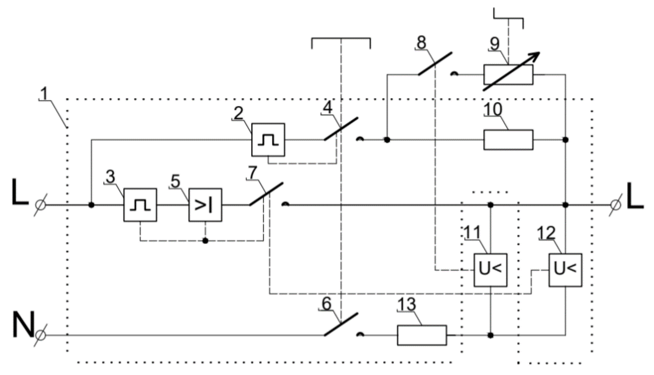
The proposed new construction of the SCB is actually based on the modification of the existing and widely used conventional SCB. All modifications were performed to achieve proper selectivity of protection devices also in cases of lowered voltage. The analyzed proposed apparatus is under patent protection and consideration [22,23] and its scheme is presented in Figure 5.
Elements included in envelope 1 are used in exploited SCB. So there can be highlighted main current path (MCP) (consisting of bi-metal 3, electromagnetic relay 5, NO contact 7), limiting current path (LCP) (consisting of bi-metal 2, NO contact 2, limiting resistor 10), voltage measurement path (VMP) (consisting of under-voltage relay 12, resistor 13 and NO contact 6). The growth of the selectivity for wide voltage range, especially for lowered voltages was achieved by adding a second under-voltage relay 11 and parallel to the resistor 10 path consisting of NO contact 8 and additional resistor 9.
When phase voltage in the installation is lower than the critical value set on the under-voltage relay 11, there is closed NO contact 8, and in consequence, the resultant resistance value in the LCP is lower than resistor 10 resistance. In this way, for lowered phase voltage the limited short-circuit current value is increased and then it is easier to achieve selectivity in protection devices work.
To avoid closing NO contact 8 during short-circuit at close to the normal phase voltage level, there is implemented time delay option. Without it, for rated voltage at the moment of fault, the voltage value can decrease to smaller than the critical value of under-voltage relay 11, and then NO contact 8 may be closed and the short-circuit current can rapidly increase.
In the presented SCB solution important is to choose the right resistor 9 value, because it has a significant impact on the limited short-circuit current value and then on the fast switching off and selectivity in protected installation. Due to it, there should be guaranteed minimal limited current value in the faulted circuit. It can be done by adding resistance according to the formula:
where: Z9—additional resistor 9 resistance, [Ω]; Z10—resistor 10 resistance, [Ω]; ZSCB—SCB resistance, [Ω].
ZSCB value is defined by subtracting line impedance from resultant loop impedance obtained from the Ohm law using minimal short-circuit current and expected voltage value:
where: ZC—impedance for the required minimal current value during expected voltage conditions, [Ω]; ZL—line impedance in the protected circuit, [Ω];
Using simple Formulas (3) and (4) there can be chosen in a very simple way proper additional resistance for various conditions which can be met in electrical installations. So there can be prepared SCB protective devices for different rated currents and different short-circuit loop-impedance.
It should be noted that mentioned formulas are written for the general case, but in low voltage installations (the installations with significant voltage drops) the supplying line and installation can be simplified only to resistance instead of impedance.
The principles of the novel SCB described above are graphically presented in Figure 6 as an algorithm.
5. Research Results
For different conventional SCB rated currents are calculated their internal resistances are responsible for short-circuit current limiting. These values are collected in Table 3.
Where: ZSCB—SCB limiting resistance, Iklim_230V—expected limited short-circuit current for 230 V, Iklim_200V—expected limited short-circuit current for 200 V, Zs_max—maximal permissible loop impedance in protected circuit.
The 3D chart presented in Figure 7 was calculated for typical SCB E25, where the resistor 10 value is 1.75 Ω. For small short-circuit loops impedances there is a need to use much more bigger values of additional resistors than in the case of high values of the loops (in analyzed case: 7 Ω for 175 V and 42 Ω for 210 V at 0 Ω line impedance versus 1.178 Ω for 175 V and 2.227 Ω for 210 V at 0.7 Ω line impedance). For voltages higher than 210 V the under-voltage relay 11 does not react and does not close the contact 8, so the apparatus works as normal SCB.
The invention allows also to adjust the resistance of the additional resistor 9 to fault conditions of the prevented circuits and can be produced in a significant range of critical voltage of the under-voltage loop and short-circuit loop impedance.
The confirmation of mentioned earlier advantages is a simulation in MATLAB/Simulink, where were performed tests according to the described rules of operating in the novel SCB for lowered supply voltages (Figure 8).
The test were made for loop impedance set as 0.125 Ω and voltage RMS value 200 V. The SCB parameters were simulated for E25 breaker. The first period after fault is the same for both cases. The difference is visible after opening contact 7 because then the short-circuit current flows only through ACP. The difference in current values is 20 A—due to the use novel circuit breaker the short-circuit current value is bigger what allows to achieve coordination between SCB with rated current 25 A and MCB with rated current 20 A and characteristic B. That arrangement was impossible to use with typical constructions of the SCBs.
Summing up, classical SCB influences the short-circuit current and limits its value below the level required by the selectivity coordination table. Proposed SCB ensures the short-circuit current on the value level allowing the release of the following protective apparatus installed closer to the place of failure.
Figure 9 is the confirmation of the presented above thesis. For the old SCB type, the limited short-circuit current is equal to 98 A. For the MCB B16, this value is acceptable and sufficient to release this breaker. But to enlarge the range of use MCB with SCB, a B20 breaker cannot be installed, because this current value is too low. For sure it should disconnect short-circuited installation within 5 s, which is not acceptable according to the law’s requirements. B20 MCB will act instantaneously with novel SCB because the short-circuit current is intentionally higher (115 A) for the same electrical system conditions. As a consequence, the selectivity range is enlarged.
Presented in Figure 10, the comparison of the short-circuit currents clearly points that the proposed SCB guarantees higher short-circuit current values for lower voltages than 200 V. Above 200 V both classical construction and novel one operates in the same conditions, so the short-circuit currents are the same. However, when the voltage is lower than 200 V, the total impedance of the SCB is lowered by the additional parallel path. In this way, for specific electrical installation conditions, it is easier to maintain the selectivity with the following MCBs, because the current value is higher and sufficient to release the protective apparatus installed closer to the failure place.
The use of the novel SCB allows installation of both B16 and B20 MCBs and in these conditions, all requirements are fulfilled. In this way, the tables given by the circuit breakers manufacturers are effectively broadened. The difference between MCB and SCB installed together may be reduced to the difference of one row. An example of the proposed coordination Table 4.
The boundary resistance and current values were calculated as maximal or minimal permissible parameters. To achieve coordination between e.g., SCB E25 and MCB B20 in the proposed solution maximal resistance of the additional limiting resistor is equal to 6.08 Ω. This value guarantees proper coordination with the maximal loop impedance 0.75 Ω.
Where: ZSCB_200V—required SCB limiting resistance for 200 V, Z9—maximal additional resistance value, Iklim_200V—expected limited short-circuit current for 200 V, Zs_max—maximal permissible loop impedance in protected circuit.
It should be noted, that the expected limited short-circuit current values in Table 5 for 200 V are calculated as minimal values needed to release the MCB one row higher than proposed manufacturers. For the safety of the solution taken, additional resistance values need to be lower.
6. Conclusions
The presented SCB solution allows us to achieve better selectivity in electrical installations with especially alternating supplying voltage profile considering voltage drops. The simplicity of the presented protective apparatus is a great advantage resulting in a very easy way to implement that device into mass production and usage worldwide. Additional elements can be considered as a multiplication of existing additional resistance and under-voltage relay is used nowadays SCB, so there is kept modular construction of proposed SCB.
What is important, especially in rural areas, there can occur significant voltage drops which directly impact the short-circuit current value conditions and then on the fast switching-off possibility. Local energy sources supplying protected installation do not guarantee a stiff voltage profile and change its value when especially high power loads turn on. Specified cases are only examples of possible situations occurring lowered voltage in installation. And for these cases, the new proposition of the SCB is a solution to possible problems in installation protection.
The described proposition also allows us to extend the range of cooperating in one installation circuit breakers. Using the new apparatus can eliminate restrictions given by SCB and MCB manufacturers, which results in an easier way of achieving selectivity in the installations.
Author Contributions
Conceptualization, B.R. and P.A.; methodology, B.R. and P.A.; software, P.A.; validation, B.R., P.A. and P.C.; formal analysis, B.R. and P.A.; investigation, B.R. and P.A.; resources, B.R. and P.A.; data curation, B.R.; writing—original draft preparation, P.A.; writing—review and editing, B.R. and P.C.; visualization, B.R., P.A. and P.C.; supervision, B.R. and P.C. All authors have read and agreed to the published version of the manuscript.
Funding
This work presented in this paper was funded by subsidies on science granted by Polish Ministry of Science and Higher Education for Cracow University of Technology.
Institutional Review Board Statement
Not applicable.
Informed Consent Statement
Not applicable.
Data Availability Statement
Not applicable.
Acknowledgments
Not applicable.
Conflicts of Interest
The authors declare no conflict of interest.
References
- Kacejko, P.; Machowski, J. Short Circuits in the Electroenergetic Systems; WNT: Warszawa, Poland, 2020. (In Polish) [Google Scholar]
- Bayliss, C.R.; Hardy, B.J. Chapter 11—Fuses and Miniature Circuit Breakers. In Transmission and Distribution Electrical Engineering, 4th ed.; Elsevier: Amsterdam, The Netherlands, 2012; pp. 361–395. ISBN 9780080969121. [Google Scholar] [CrossRef]
- Markiewicz, H. Bezpieczeństwo w Elektroenergetyce: Zagadnienia Wybrane; WNT: Warszawa, Poland, 2013; ISBN 9788363623463. [Google Scholar]
- IEEE Recommended Practice for Protection and Coordination of Industrial and Commercial Power Systems (IEEE Buff Book). In IEEE Std 242-2001 (Revision of IEEE Std 242-1986) [IEEE Buff Book]; IEEE xplore: New York, NY, USA, 2001; pp. 1–710. [CrossRef]
- Ding, Q.; Chen, Y.; Chen, L. Selective Switch with Selective Protective Module. Shanghai Electric Appliance SC. CN Patent 1617405A, 18 May 2005. Available online: https://patents.google.com/patent/CN100428603C/en (accessed on 9 October 2021).
- Kelaiditis, K. Line and/or apparatus protection circuit breaker against excess current and short circuit, HAGER ELECTRO GMBH & CO. DE Patent 3316230, 19 August 2002. [Google Scholar]
- Vidmar, S.; Dolnisek, M. Automatic Electric Switch, Eti Elektroelement DD. SI Patent 22187, 29 December 2005. [Google Scholar]
- Mamcarz, D.; Albrechtowicz, P.; Radwan-Pragłowska, N.; Rozegnał, B. The Analysis of the Symmetrical Short-Circuit Currents in Backup Power Supply Systems with Low-Power Synchronous Generators. Energies 2020, 13, 4474. [Google Scholar] [CrossRef]
- Albrechtowicz, P.; Szczepanik, J. The Analysis of the Effectiveness of Standard Protection Devices in Supply Systems Fed from Synchronous Generator Sets. In Proceedings of the 2018 International Symposium on Electrical Machines (SME), Andrychów, Poland, 23 August 2018; pp. 1–5. [Google Scholar] [CrossRef]
- Rozegnał, B.; Albrechtowicz, P.; Mamcarz, D.; Radwan-Pragłowska, N.; Cebula, A. The Short-Circuit Protections in Hybrid Systems with Low-Power Synchronous Generators. Energies 2021, 14, 160. [Google Scholar] [CrossRef]
- Ludwinek, K.; Szczepanik, J.; Sułowicz, M. Experimental analysis of assessing of the tripping effectiveness of miniature circuit breakers in an electrical installation fed from a synchronous generator set. Electr. Power Syst. Res. 2017, 142, 341–350. [Google Scholar] [CrossRef]
- Radwan-Pragłowska, N.; Węgiel, T.; Borkowski, D. Modeling of Axial Flux Permanent Magnet Generators. Energies 2020, 13, 5741. [Google Scholar] [CrossRef]
- Radwan-Pragłowska, N.; Węgiel, T.; Borkowski, D. Parameters identification of coreless axial flux permanent magnet generator. Arch. Electr. Eng. 2018, 67, 391–402. [Google Scholar] [CrossRef]
- Borkowski, D.; Majdak, M. Small Hydropower Plants with Variable Speed Operation—An Optimal Operation Curve Determination. Energies 2020, 13, 6230. [Google Scholar] [CrossRef]
- Smugala, D. Switching-On Operation of an Electromagnetic Relays Optimization Using a Phase Control Approach. IEEE Trans. Ind. Electron. 2021, 68, 6152–6160. [Google Scholar] [CrossRef]
- Smugala, D.; Bonk, M. Switching Arc Energy Limitation Approach for LV Circuit Breakers. Energies 2021, 14, 6774. [Google Scholar] [CrossRef]
- Larsen, E. A new approach to low-voltage circuit breaker short-circuit selective coordination. In Proceedings of the 2008 IEEE/IAS Industrial and Commercial Power Systems Technical Conference, Clearwater Beach, FL, USA, 22 August 2008; pp. 1–7. [Google Scholar] [CrossRef]
- Belometti, M.; Bettinelli, P.C.; Fidigatti, A.; Ragaini, E. Full digital architecture for selective protection coordination in low voltage electrical installations. In Proceedings of the 2017 IEEE International Conference on Environment and Electrical Engineering and 2017 IEEE Industrial and Commercial Power Systems Europe (EEEIC/I&CPS Europe), Milan, Italy, 13 July 2017; pp. 1–4. [Google Scholar] [CrossRef]
- SENTRON Podręcznik Selektywności; Energy Management: Warszawa, Poland, 2018. (In Polish)
- Aparatura Niskich Napięć. Zeszyt Projektanta; ABB: Warszawa, Poland, 2015. (In Polish)
- Regulation of the Minister for Infrastructure and Construction Amending the Regulation of the Minister for Infrastructure of 12 April 2002 on the Technical Conditions to Be Met by Buildings and Their Location, Dz.U. 2002 nr 75 poz. 690. Available online: http://isap.sejm.gov.pl/isap.nsf/download.xsp/WDU20020750690/O/D20020690.pdf (accessed on 15 June 2002).
- Rozegnał, B.; Albrechtowicz, P. Patent Application 435290. (In Polish). Available online: http//:uprp.gov.pl (accessed on 10 September 2021).
- Rozegnał, B.; Albrechtowicz, P. Patent Application 435291. (In Polish). Available online: http//:uprp.gov.pl (accessed on 10 September 2021).
Figure 1.
The diagram shows the idea of the selective operation of electrical installation protections [1].
Figure 1.
The diagram shows the idea of the selective operation of electrical installation protections [1].

Figure 2.
An example of the SCB electrical scheme.

Figure 3.
Simplified short-circuit scheme.

Figure 4.
An impact of voltage value on the expected short-circuit currents in installation with (red) or without (blue) selective circuit breaker.
Figure 4.
An impact of voltage value on the expected short-circuit currents in installation with (red) or without (blue) selective circuit breaker.

Figure 5.
A scheme of the new SCB for lowered supply voltages.

Figure 6.
An algorithm of operating in the proposed novel SCB.

Figure 7.
The relationship between the additional impedance of the limiting resistor 9 and phase voltage value and short-circuit impedance loop of the protected installation.
Figure 7.
The relationship between the additional impedance of the limiting resistor 9 and phase voltage value and short-circuit impedance loop of the protected installation.

Figure 8.
The comparison of the short-circuit current waveforms for novel and typical SCB.

Figure 9.
B16 and B20 curves with expected short-circuit currents with or without the proposed breaker.
Figure 9.
B16 and B20 curves with expected short-circuit currents with or without the proposed breaker.

Figure 10.
Short circuit currents comparison for classical and proposed SCB construction in case of line impedance from 0.01 to 0.96 Ω and threshold undervoltage value 200 V: continuous line—proposed SCB, dotted line—for classical SCB.
Figure 10.
Short circuit currents comparison for classical and proposed SCB construction in case of line impedance from 0.01 to 0.96 Ω and threshold undervoltage value 200 V: continuous line—proposed SCB, dotted line—for classical SCB.


Table 1.
Maximal permissible times of off-switching in the TN system.
| Rated Phase Voltage, Uo [V] | 50 ≤ Uo ≤ 120 | 120 ≤ Uo ≤ 230 | 230 ≤ Uo ≤ 400 |
|---|---|---|---|
| Maximal permissible time of off-switching, t [s] | 0.8 | 0.4 | 0.2 |
Table 2.
Coordination table [18].
Table 2.
Coordination table [18].
| MCB/SCB In [A] | 16 | 20 | 25 | 35 | 40 | 50 | 63 |
|---|---|---|---|---|---|---|---|
| 10 | X | X | X | X | X | X | X |
| 13 | OC | X | X | X | X | X | X |
| 16 | OC | X | X | X | X | X | |
| 20 | OC | X | X | X | X | ||
| 25 | OC | X | X | X | |||
| 32 | OC | X | X | ||||
| 40 | OC | X |
X—coordination fulfilled, OC—only overcurrent coordination fulfilled.
Table 3.
Conventional SCB and circuit parameters according to the coordination table (Table 2).
Table 3.
Conventional SCB and circuit parameters according to the coordination table (Table 2).
| SCB In [A] | 16 | 20 | 25 | 32 | 40 | 50 | 63 |
|---|---|---|---|---|---|---|---|
| ZSCB [Ω] | 2.73 | 2.19 | 1.75 | 1.37 | 1.1 | 0.87 | 0.70 |
| Iklim_230V [A] | 84 | 105 | 131 | 168 | 209 | 264 | 329 |
| Iklim_200V [A] | 73 | 91 | 114 | 146 | 182 | 230 | 286 |
| Zs_max [Ω] | 1.27 | 0.89 | 0.75 | 0.63 | 0.5 | 0.37 | 0.3 |
Table 4.
Proposed new coordination table.
| MCB/SCB In [A] | 16 | 20 | 25 | 35 | 40 | 50 | 63 |
|---|---|---|---|---|---|---|---|
| 10 | X | X | X | X | X | X | X |
| 13 | X | X | X | X | X | X | X |
| 16 | X | X | X | X | X | X | |
| 20 | X | X | X | X | X | ||
| 25 | X | X | X | X | |||
| 32 | X | X | X | ||||
| 40 | X | X |
X—coordination fulfilled.
Table 5.
Conventional SCB and circuit parameters according to the coordination table (Table 2).
Table 5.
Conventional SCB and circuit parameters according to the coordination table (Table 2).
| Novel SCB In [A] | 16 | 20 | 25 | 32 | 40 | 50 | 63 |
|---|---|---|---|---|---|---|---|
| ZSCB_200V [Ω] | 1.81 | 1.61 | 1.25 | 0.97 | 0.75 | 0.67 | 0.50 |
| Zs_max [Ω] | 1.27 | 0.89 | 0.75 | 0.63 | 0.5 | 0.37 | 0.3 |
| Z9_max [Ω] | 5.37 | 6.08 | 4.4 | 3.32 | 2.36 | 2.91 | 1.75 |
| Iklim_200V [A] | 65 | 80 | 100 | 125 | 160 | 200 | 250 |
Publisher’s Note: MDPI stays neutral with regard to jurisdictional claims in published maps and institutional affiliations. |
© 2021 by the authors. Licensee MDPI, Basel, Switzerland. This article is an open access article distributed under the terms and conditions of the Creative Commons Attribution (CC BY) license (https://creativecommons.org/licenses/by/4.0/).
Share and Cite
MDPI and ACS Style
Rozegnał, B.; Albrechtowicz, P.; Cisek, P. A Novel Low Voltage Selective Circuit Breaker with Additional Current Path. Energies 2021, 14, 8179. https://0-doi-org.brum.beds.ac.uk/10.3390/en14238179
AMA Style
Rozegnał B, Albrechtowicz P, Cisek P. A Novel Low Voltage Selective Circuit Breaker with Additional Current Path. Energies. 2021; 14(23):8179. https://0-doi-org.brum.beds.ac.uk/10.3390/en14238179
Chicago/Turabian StyleRozegnał, Bartosz, Paweł Albrechtowicz, and Piotr Cisek. 2021. "A Novel Low Voltage Selective Circuit Breaker with Additional Current Path" Energies 14, no. 23: 8179. https://0-doi-org.brum.beds.ac.uk/10.3390/en14238179
Note that from the first issue of 2016, this journal uses article numbers instead of page numbers. See further details here.