
Efficient Wireless Drone Charging Pad for Any Landing Position and Orientation


1
Department of Industrial and Information Engineering and Economics, University of L’Aquila, 67100 L’Aquila, Italy
2
Department of Astronautics, Electrical and Energetics Engineering, Sapienza University of Rome, 00184 Rome, Italy
*
Author to whom correspondence should be addressed.
Energies 2021, 14(23), 8188; https://0-doi-org.brum.beds.ac.uk/10.3390/en14238188
Submission received: 8 November 2021
/
Revised: 25 November 2021
/
Accepted: 30 November 2021
/
Published: 6 December 2021
(This article belongs to the Special Issue Intelligent Wireless Power Transfer System and Its Application 2021)
Abstract
:A wireless charging pad for drones based on resonant magnetic technology to recharge the internal battery is presented. The goal of the study was to design a robust, reliable and efficient charging station where a drone can land to automatically recharge its battery. The components of the wireless power transfer (WPT) system on board the drone must be compact and light in order not to alter the payload of the drone. In this study, the non-planar receiving coil of the WPT system is integrated into the drone’s landing gear while the transmitting pad is designed to be efficient for any landing point and orientation of the drone in the charging pad area. To meet these requirements, power transmission is accomplished by an array of planar coils integrated into the ground base station. The configuration of the WPT coil system, including a three-dimensional receiving coil and a multicoil transmitter, is deeply analyzed to evaluate the performance of the WPT, considering potential lateral misalignment and rotation of the receiving coil due to imprecise drone landing. According to the proposed configuration, the battery of a light drone (2 kg in weight and 0.5 kg in payload) is recharged in less than an hour, with an efficiency always greater than 75%.
1. Introduction
Unmanned aerial vehicles (UAVs) are becoming increasingly popular in various fields, including surveillance, delivering and monitoring [1]. Lightweight drones are generally equipped with a number of rotors, between 4 and 8. Drones’ electric power is supplied by a lithium battery pack, which allows a flight time of up to 40 min [2]. Since this time may be insufficient for some applications, the use of drones is severely limited. To increase operating times, drones can be equipped with a higher capacity battery, but this leads to an increase in weight and, consequently, a reduction in payload. Alternatively, the mission time can be extended by quickly charging the battery. However, this operation currently requires human intervention. A current challenge is to allow drones to operate with complete autonomy. A possible solution to achieve this goal consists in designing a ground base station (landing pad) where the drone lands for automatically recharging its batteries by using near field (inductive) wireless power transfer (WPT) technology. This technology, which is widely used currently in several applications, allows a very efficient and reliable power transmission between the ground base station, which hosts a transmitting coil, and the drone equipped with a receiving coil installed on board the drone [3,4,5,6,7,8,9]. The application of WPT technology must account for several aspects, mainly related to the additional weight on board, which must be limited as much as possible. Another critical aspect is the possible misalignment of the WPT coils due to the imprecise landing of the drone, which can lead to a reduction in the coupling factor between the transmitting and receiving coils, and therefore in the WPT’s electrical performance. These two aspects have been studied in the recent past, and different solutions have been presented [10,11,12,13,14,15,16,17,18]. In [10], an inductive charging system is proposed that adopts a small receiving coil placed on the landing gear of the drone. This solution offers the advantage of an extremely limited vertical separation between the transmitter and the receiver. However, the presence of the receiving coil could interfere with the view of any cameras on board. In [11], the drone is equipped with a large receiving coil, assuring good electrical performances in terms of power transfer, but with a significant extra weight on board. In [12], a charging system for small drones is presented that includes a transmitter and a receiver made with multiple coils. A critical aspect of this solution is that the multiple receiving coils mounted on the drone’s underbody limit applications that require the installation of payloads under the drone. An automatic alignment system is proposed in [13], in which the transmitting coil is placed on a movable plane within the landing pad, and its position is adjusted to meet the alignment condition after landing. This solution makes it possible to improve the electrical performance but significantly reduces the reliability due to the presence of movable parts. The use of a movable plane is also investigated in [14], together with the use of an array of primary coils. An advanced algorithm is presented to guarantee a fast and accurate alignment between transmitting and receiving coils. In [15], a charging system using capacitive WPT is designed. In this case too, the main limitations are the weight and limited ground clearance required to achieve good performance. In [16], a capacitive wireless coupling system is proposed, operating at the frequency of 6.78 MHz; in experimental tests, an efficiency of 50% was obtained, with an output power of about 12 W. In [17], an inductive WPT system operating at a frequency of 300 kHz is described; the system is designed to reduce extra on-board weight and to achieve an efficiency up to 90%. In [18], an optimization design for the coils is provided to reduce weight and improve tolerance of misalignment. The proposed method is validated with a prototype operating at a frequency of 164 kHz. A mid-frequency system is presented in [19], where the WPT system is used to power a small drone. A full review of the charging systems for drones can be found in [20,21,22].
All the proposed solutions were mainly derived from previous WPT applications in other fields, such as automotive or consumer electronics, and adapted to drones [23]. In this study, an improved solution is proposed that combines the following three main advantages over current alternatives:
- −
- Full integration in the landing gear of the receiving coil, meaning that no extra weight and no reduction in payloads occur;
- −
- High tolerance of misalignment conditions through the adoption of an array of planar transmitting coils in the ground base station;
- −
- High charging power and good electrical efficiency for every possible drone landing position and orientation in the ground base station.
The solution proposed in this paper combines the benefits provided by the enhanced landing gear, which acts as a WPT receiver [17], with the simplicity of a smart multicoil landing pad, where, depending on the drone’s landing position, only one coil of the transmitting array is active during the charging process.
2. WPT Equivalent Circuit
The proposed charging system is based on inductive resonant technology, which is itself based on the magnetic coupling between two or more coils. In the following, the receiving coil is assumed to be installed on the drone while the multiple coils transmitting system is placed in the ground base station.
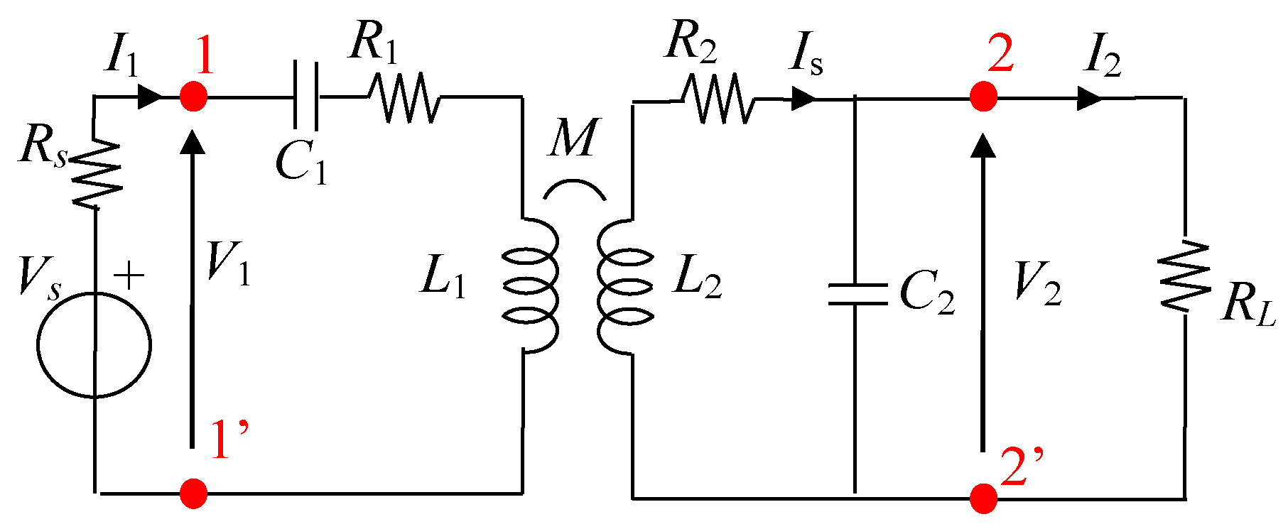
A standard two-coil WPT system, made by a single coil transmitter, can be suitably represented by the equivalent circuit shown in Figure 1, where: the inductive coupling is modeled by the self-inductances L1 and L2 and by the mutual inductance M [3]; and the ohmic losses are modeled by the resistances R1 and R2 for the transmitting (primary) and receiving (secondary) coils, respectively. The series-parallel (SP) compensation topology is adopted, since this topology allows greater efficiency when the number of turns of the secondary coil is small, as described in [10,11]. The capacitor C1 is connected in series with the transmitting coil, while the capacitor C2 is connected in parallel with the receiving coil. The values of C1 and C2 are adequately chosen to obtain the resonance condition at the same operational angular frequency ω0 = 2πf0 as:
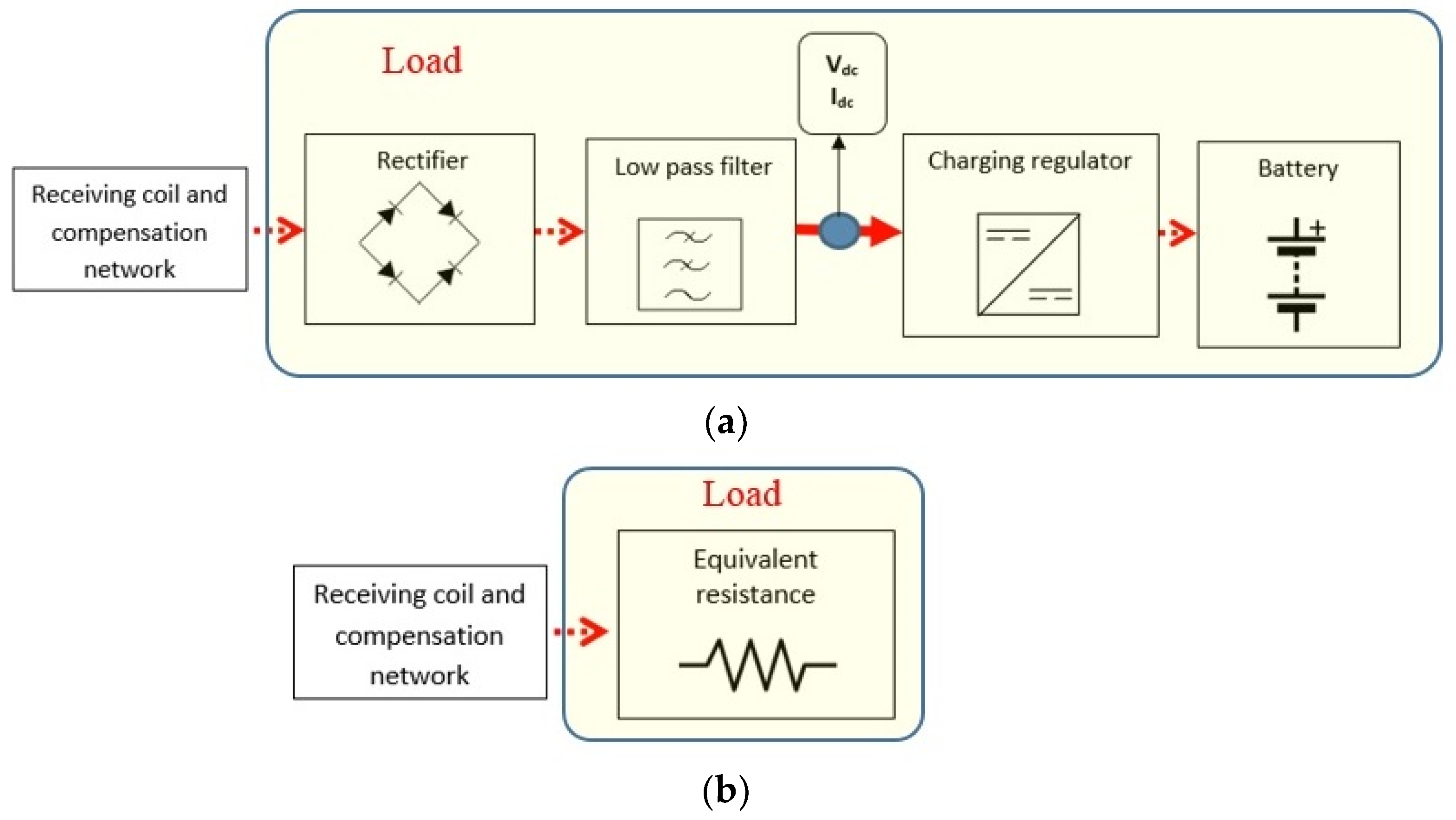
In the proposed application, the operational frequency is set to f = 300 kHz to obtain a good trade-off between good magnetic coupling and low electronic losses [17]. In the simplified circuit, both source and load blocks are modeled by simple equivalent analogical devices as the attention is focused on coupling mechanism, which allows wireless power transmission. The primary coil is fed by a time-harmonic voltage source with a small internal resistance Rs; in reality, the feeding block includes converters (i.e., a rectifier and an inverter). A similar simplification is adopted for the load, here modeled by a simple resistance RL at resonance while in real world it includes an AC/DC converter (i.e., a rectifier), a charging regulator and a battery, as shown in Figure 2. From the battery specification, it is possible to approximately calculate the value of the equivalent resistance Rdc. This value depends on the voltage and current waveforms in the receiving coil, but for the sake of simplicity and without introducing a large approximation, the load resistance RL before the rectifier is assumed to be
where Vdc and Idc are the voltage and current after the rectifier, respectively, when neglecting the losses in the AC/DC converter.
The efficiency η is evaluated as
where PL is the real power on the resistive load RL (i.e., port 22’ in Figure 1), given by:
and P1 is the real power at the input port 11’ of the transmitting circuit given by
with V1 and I1 the voltage and current at the input port (i.e., port 11’ in Figure 1).
In terms of the values of the lumped circuit parameters, the AC resistances R1 modeling the ohmic losses on the primary coils, are directly obtained from the Litz wire datasheet. The inductances L1 and L2 and M are calculated by post-processing the magnetic field distribution in the considered domain, which can be obtained through the numerical solution of the time-harmonic magneto-quasi-static (MQS) field equations, using the finite element method (FEM). The simulations are performed in this work using the commercial software COMSOL for solving the magnetic field equations:
where µ is the magnetic permeability, σ is the electric conductivity, B is the magnetic flux density, Je is the external current density, A is the magnetic vector potential and V is the electric potential. Magnetic insulation is imposed at the external boundaries of the computational domain, far from the source. The coils are modelled as 1D loops, where the currents are imposed using the Edge Currents tool. In the presence of thin conductive material, the Transition Boundary Conditions (TBCs) can be applied to reduce the computational cost as they avoid the discretization of the conductive regions. The theory of TBC can be found in [24,25].
The parameters of the coils in terms of self and mutual inductances are calculated by applying Ohm’s law, as described in [5]. The coupling factor k between the coils is obtained by:
Playing an important role in the inductive coupling, k should be maximized. Typically, k depends on magnetic coupling: k increases as coil size increases, and k decreases as the separation distance increases. In our application for drone battery charging, the coil size is limited by the dimension of the considered drone, while the separation distance between transmitting and receiving coils should be reduced as much as possible.
At the resonance angular frequency ω0 = 2π f0, by replacing the capacitors C1 and C2 given by (1) in (8), the input impedance becomes:
3. System Configuration
- A.
- WPT Design Specifications
To design the charging system of a drone, several aspects need to be considered. First, when the battery is low, the UAV will return to the landing pad using the autopilot and automatic landing procedure. There are several methods that can be used to improve landing accuracy. However, an external factor (e.g., strong wind) can significantly affect the accuracy of the final landing, and in case of an incorrect landing, a second attempt is not always practicable in low-battery conditions. To this end, the landing pad must be suitably sized to ensure a considerable tolerance of any imprecision in landing, which often involves a strong misalignment between the receiving and transmitting coils.
The electrical characteristics of the charging system mainly depend on the battery of the drone. Typically, drones use high-energy-density batteries, capable of high discharge and charge current. In this study, a medium-sized drone is considered, with an empty weight of around 2 kg and frame dimensions of around 500–600 mm. The typical payload of this kind of drone is about 0.5 kg. Battery pack configuration is a function of desired range, flight agility and flight time. A typical battery consists of four LiPo cells connected in series, for a total voltage Vbat = 14.4 V. It can be assumed that the battery capacity is 5 Ah, so that the total energy is Ebat = 72 Wh.
Thus, the power Pwpt requested from the charging system can be expressed in relation to the desired charging time Tch, expressed in hours as
Typically, a charging time of one hour is a worthwhile trade-off in order to obtain fast charging without degrading the batteries. Thus, a charging time Tch = 1 h is adopted here, which corresponds to a charging power of Pwpt = 72 W. The equivalent resistance is approximately RL = 2.9 Ω.
The maximum misalignment that the system can tolerate is provided by the precision of the drone landing. For this application, a drone equipped with a GPS Real-Time Kinematic (RTK) system is considered [2]. This technology allows a very precise position reference (less than 20 cm) in ideal conditions; however, a maximum misalignment of +/−50 cm is considered here as the worst case. To allow wireless battery charging even in the event of an imprecise landing, it is necessary to suitably size the landing pad and, therefore, the transmitting coil embedded in it. However, as a larger transmitting coil would lead to a reduction in the coupling factor and, therefore, in electrical efficiency, its dimension cannot be increased. To overcome these disadvantages, an innovative array of planar transmitting coils is proposed to improve tolerance to misalignment conditions while maintaining the transmitting and receiving coils at similar dimensions. The proposed solution can also benefit from a reduced separation distance between the coupled coils as the receiving coil is fully integrated in the drone’s landing gear. A further advantage of this solution is the reduced additional equipment (low weight gain) for the onboard WPT receiver and a near-total lack of reduction in payload.
Once the requirements for the electrical performance of the WPT system and the tolerance to misalignment of the coils have been established, the focus is on the design of the WPT coils. In the following, the receiving coil design is addressed first as it is constrained by the geometric shape of the drone, followed by the design of the transmitting coils array.
- B.
- WPT Coil Design
(1) Receiving Coil Integrated in the Landing Gear
In the proposed solution, the receiving coil is the landing gear itself. Therefore, the landing gear is designed to also act as receiver coil of the WPT system, as described in [17]. To this end, the shape and material of the landing gear is very important to ensure mechanical strength and good electrical performance. The drone’s standard landing gear, typically made from plastic or composite materials, such as carbon fiber or Kevlar, is replaced with a new landing gear made from an aluminum tube. Aluminum is preferred to other materials with higher conductivity, such as copper, due to its very good mechanical properties and low weight. Furthermore, a hollow cylindrical section of the aluminum tube leads to a very low resistance, even in AC, as the skin effect at the frequency considered does not significantly reduce the area of the conductive tube section where the current flows if the thickness of the tube is lower than penetration depth.
The shape of the landing gear was selected by considering two main aspects: improving the coupling factor k and ensuring adequate distance of the drone body from the ground. The landing gear used in the present study is shown in Figure 3a. If necessary, this shape can be modified in case of special requirements, by varying its height from the ground or by installing a suitable payload. The dimensions of the landing gear are constrained by the size and weight of the drone. For a drone with a frame size of 550 mm, the dimensions of the landing gear used as the receiving coil are d1 = 30 cm, d2 = 20 cm, d3 = 25 cm, d4 = 10 cm and d5 = 15 cm, as shown in Figure 3b. It should be noted that the size of the landing gear is significantly smaller than the wavelength at 300 kHz, that is, about 1000 m. The electrical parameters of the landing gear in terms of self-inductance and self-resistance are obtained by calculation and measurement. The external inductance was calculated by a MQS field analysis while the AC resistance of the landing gear was measured by an RLC meter at the considered frequency [17]. The obtained values were L2 = 1.33 μH and R2 = 33 mΩ.
(2) Transmitting Coils Array
The transmission system is mainly designed to ensure efficiency above a fixed level and the minimum area of the ground station where the drone battery can be recharged. In this case, having selected a misalignment tolerance of +/−50 cm, the charging area is assumed to be 1 m2. It is clear that with such a large charging area demand, a single primary coil, much larger than the secondary coil, leads to very poor coupling factor k and electrical efficiency η. To avoid this inconvenience, an array of square transmitting coils is proposed, with the goal of assuring an efficiency in the landing area η ≥ 75% for any possible landing position and orientation of the drone in the ground pad.
The proposed array of square transmitting coils is designed through the following two investigations aimed at:
- detecting the maximum size of the single transmitting coil suitable to meet the efficiency target for the admissible lateral offset;
- defining the array in terms of number, size and position of the coils.
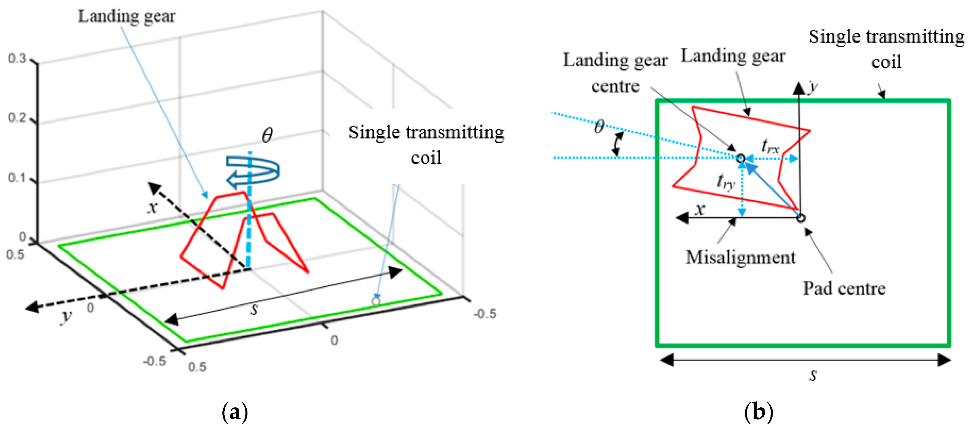
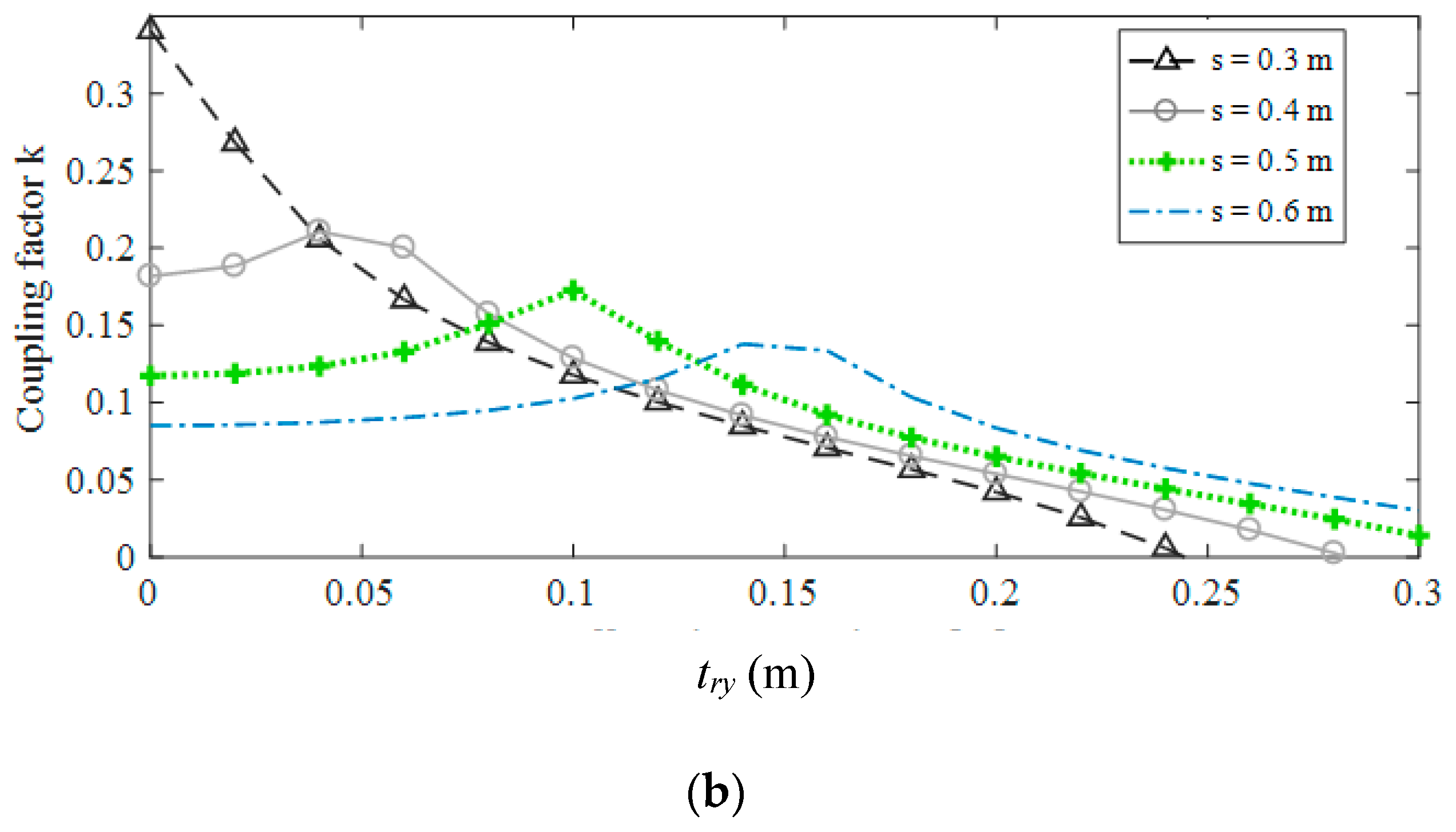
A sketch of the adopted coil configuration used in the first investigation is shown in Figure 4. Due to the particular conformation of the receiving coil with a three-dimensional shape, lateral misalignment in both directions (x- and y-axes) is considered. The coupling factor k between the landing gear/receiving coil and a square-shaped transmitting coil is calculated by varying the size of the transmitting coil (side length s) and the lateral offset along the x-axis (trx) and the y-axis (try). The allowable length of the s side of the transmitting coil is set in the range 0.3–0.6 m. A smaller size for s is not considered as the transmitting coil would be smaller than the receiving coil (i.e., landing gear). Conversely, a larger transmitting coil would produce too large a magnetic flux leakage. The maximum lateral offset is set at trmax = 0.3 m in both the x- and y-axis directions.
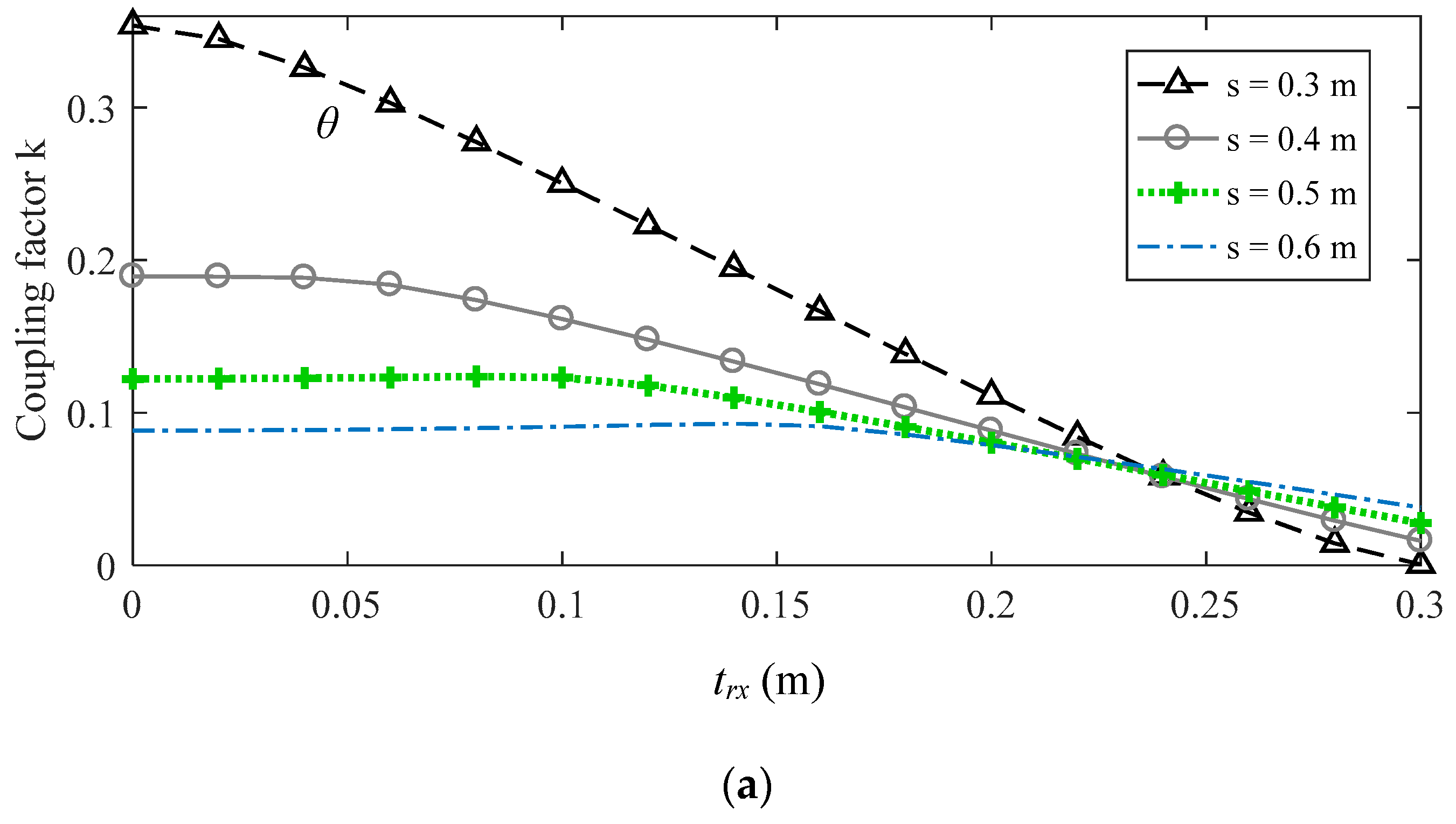
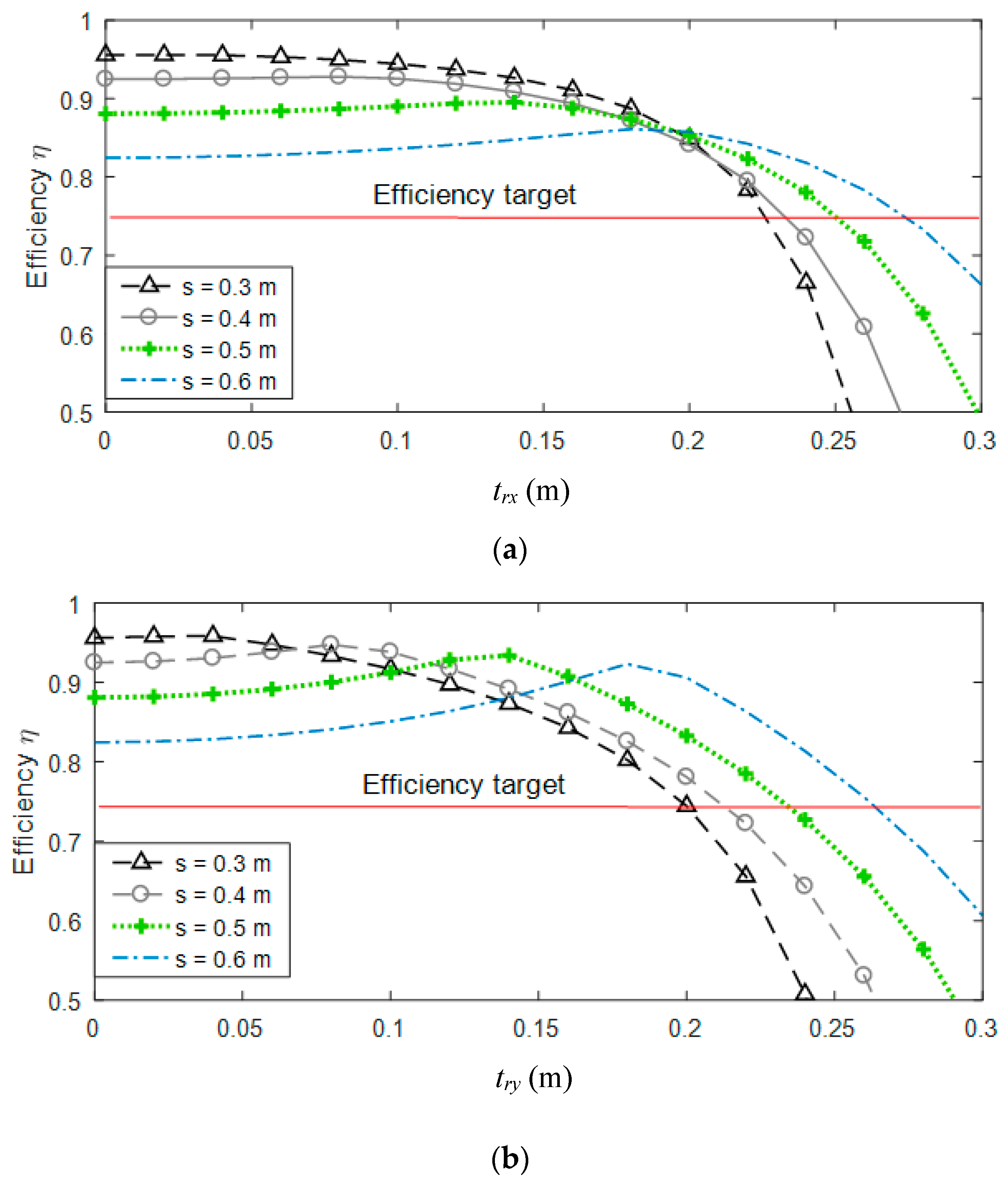
The calculation of the coil parameters was performed through an MQS field analysis, discretizing the computational domain in 187,452 elements using a tetrahedral mesh. The results obtained in terms of coupling factor k vs. offsets trx and try for different values of transmitting coil side s are shown in Figure 5. For each configuration considered, the electrical efficiency η was also calculated from the analysis of the equivalent electrical circuit, considering N1 = 10 turns of the primary coil and RL = 2.9 Ω, as shown in Figure 6. For all the calculations, the input voltage was adjusted to obtain a fixed output power P2 = 72 W. The efficiency, defined by (3), was calculated through the analysis of the equivalent circuit of Figure 1. The design target for the efficiency was set at η ≥ 75%. A minimum efficiency of 75% is assumed to be very good for this type of application, considering the high variability of the drone’s landing position. Furthermore, this efficiency value does not degrade the wireless charging process. However, the efficiency target is an input design parameter and can be varied.
An efficiency of η ≥ 75% was obtained using the largest coil with s = 0.6 m for an offset up to 27 cm. As can be seen, the efficiency exhibited a different behavior if we considered the misalignment on the x- and y-axes due to the asymmetrical shape of the receiving coil; however, the system makes it possible to maintain an efficiency greater than the target (η ≥ 75%) for both directions.
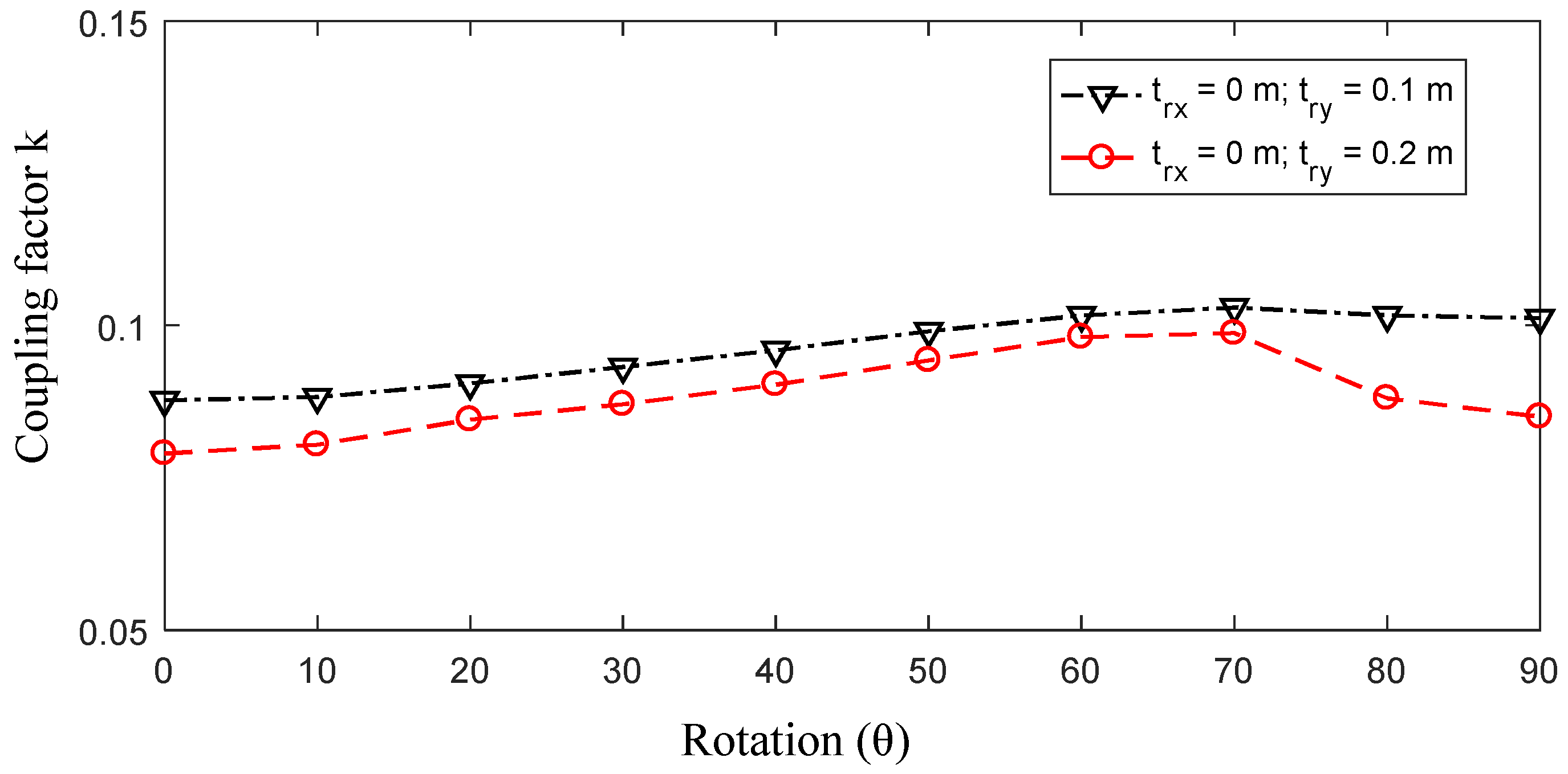
For this configuration, the tolerance of possible yaw (rotation on the vertical axis) during landing was investigated. Although the angular precision of the autopilot can be very high, possible rebounds during the landing can significantly modify the final angular position θ. Thus, yaw angles from θ = 0 to θ = 90° were considered. The coupling factor k, considering two different positions of the drone, is shown in Figure 7, demonstrating that k is not strongly influenced by the possible rotation θ of the drone.
The electrical quantities calculated by the equivalent circuit analysis for θ = 0, s = 0.6 m, as well as for different values of the coupling factor k, are reported in Table 1.
To extend the tolerance of the system at trx ≤ 50 cm and try ≤ 50 cm (landing area 1 m2), an array of multiple transmitting coils was adopted. With four transmitting coils, arranged as a 2 × 2 matrix, it was possible to obtain η ≥ 75% for any lateral offset trx ≤ 54 cm and try ≤ 54 cm. The four planar coils were partially overlapped for a distance Op = s/2–trmax = 3 cm, to avoid areas (from trmax–s/2) where the efficiency was below the efficiency target. It should be noted that trmax for the considered case of square coils is assumed to be the same on both x and y axis. The conductors of the transmitting coils were insulated with a thin layer of plastic to avoid electrical contact between them.
To improve the efficiency of the system, considering the most probable landing position (offset nearly zero in each direction), an additional identical fifth coil was placed at the center of the ground pad. The proposed final configuration of the primary five-coil array is shown in Figure 8, where the five planar square coils with side s are depicted using brown, blue, light blue, green and yellow lines. Only one transmitting coil in the array is activated in the ground pad depending on the drone’s landing position.
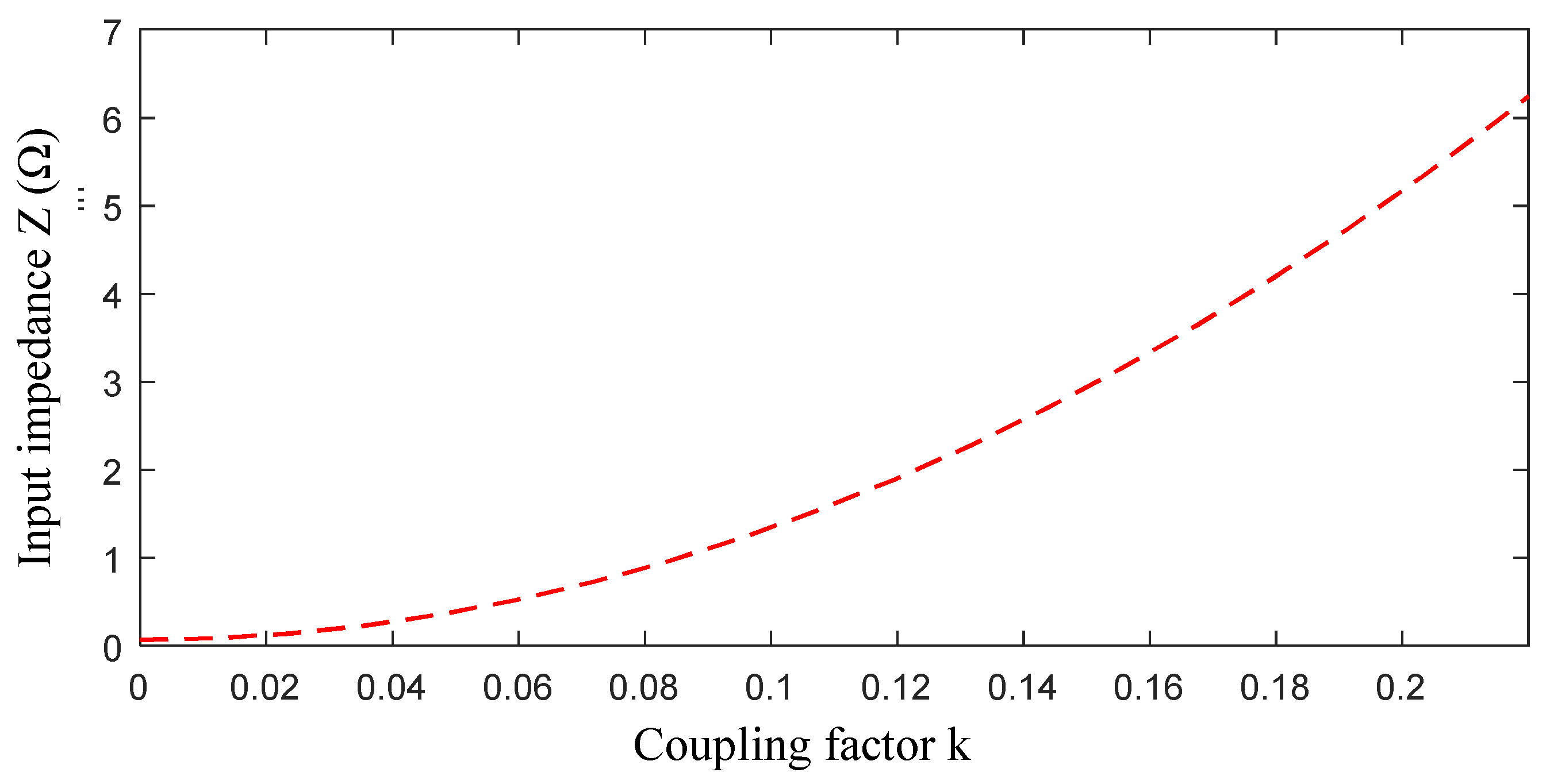
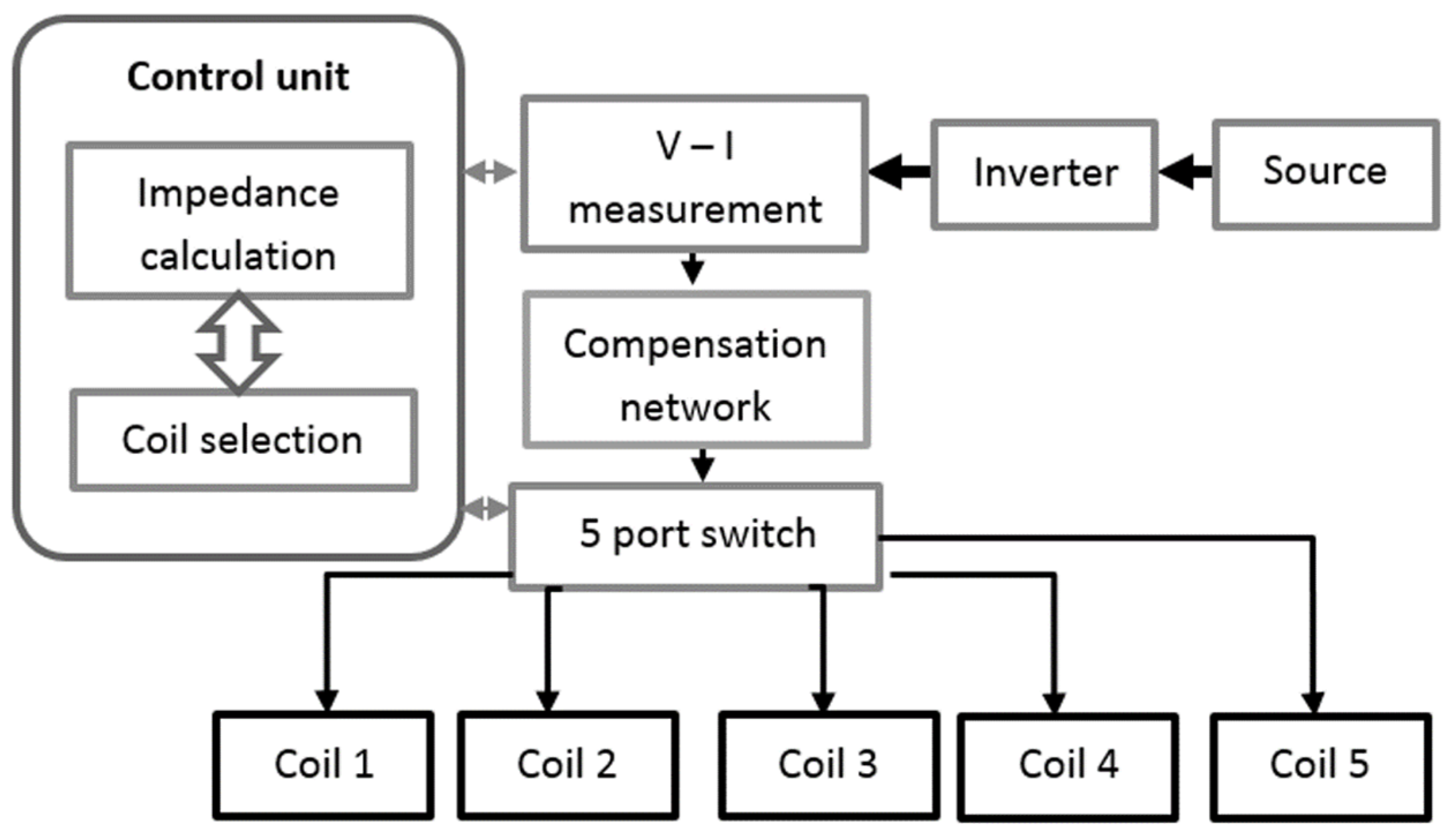
The input impedance Zin in (9) is strongly dependent on the mutual inductance M, which is proportional to the coupling factor k. A graph of the input impedance Zin vs. k is shown in Figure 9. A higher value of the coupling factor k, or mutual inductance M, generally leads to an increase in electrical efficiency [4], as can also be seen from (10). The procedure for choosing the coil in the landing pad to be activated is as follows: after the drone has landed, the electronic unit powers one transmitting coil at a time to evaluate its input impedance Zin and memorize this value. In this way, Zin is evaluated for all five landing pad coils. At the end of polling, the coil that features the highest Zin input impedance is selected as the transmitting coil to be activated. The input impedance Zin is calculated by measuring the input voltage V1, the input current I1 and the phase between them. A block diagram summarizing the selection of the transmission coil, in which there is a five-port switch controlled by the control unit to select the best transmitting coil, is presented in Figure 10.
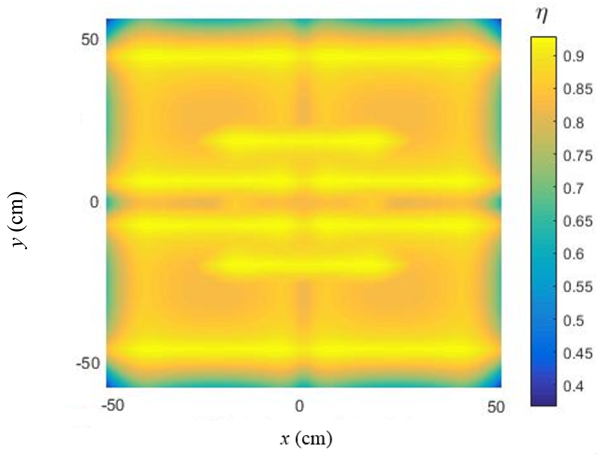
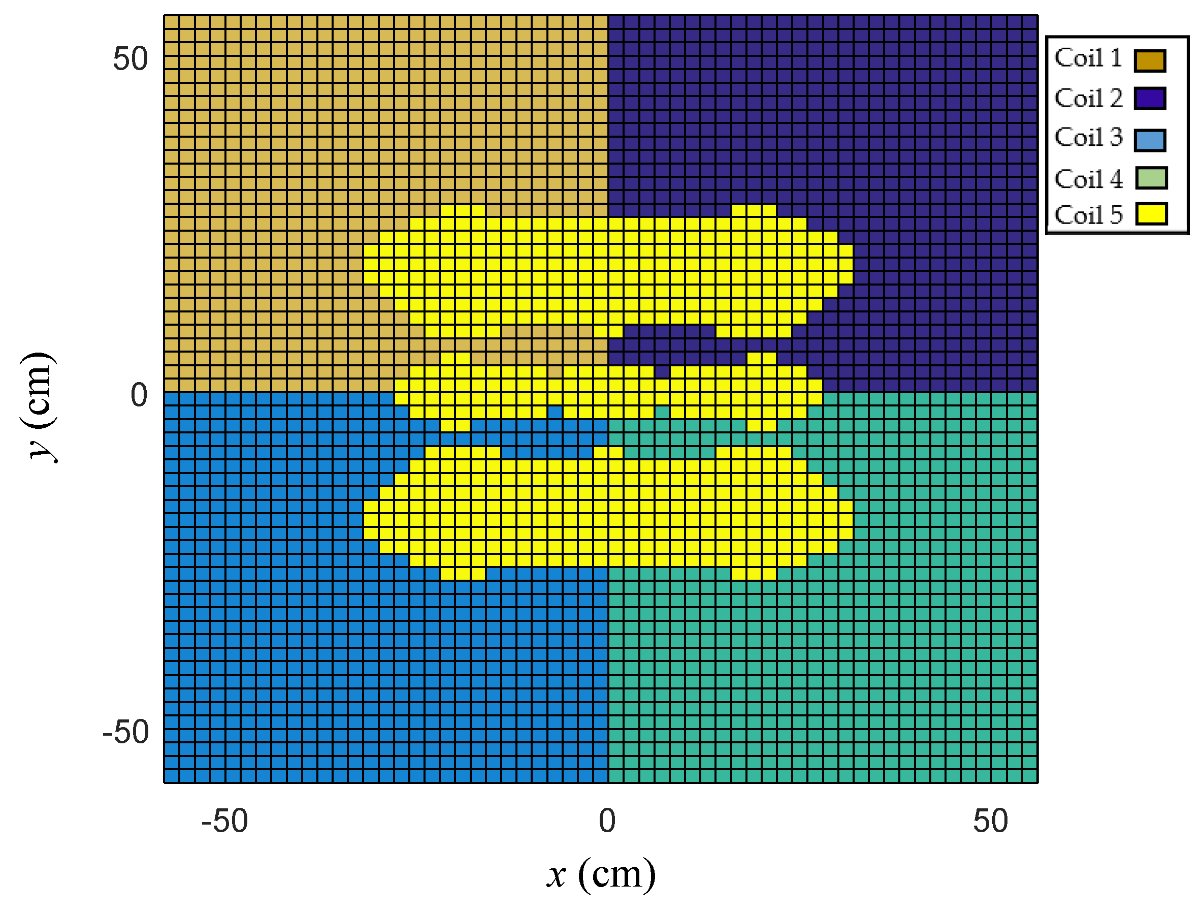
The efficiency was calculated for any point on the ground pad where the drone can land. The transmitting coil that guarantees maximum electrical efficiency among the five coils was also identified. The map of the efficiency for any landing position (x, y) is shown in Figure 11, where it can be observed that η ≥ 75% at any point in the charging area. From an electrical point of view, only one of the five transmitting coils of the array is used at a time, depending on the position of the drone on the ground pad. The map reported in Figure 12 shows which coil should be activated for each point (x, y) in the landing pad considering a yaw angle θ = 0. The asymmetrical behavior of the efficiency map in the center of the ground pad is due to the asymmetrical design of the receiving coil/landing gear. It should be noted that when a coil is selected for charging, the others are in an open-ended condition; thus, they do not interfere with the charging coil.
4. Conclusions
An innovative, high-efficiency WPT system to automatically recharge the battery of a drone was presented. The additional equipment of the WPT system to be mounted on board the drone must be greatly reduced. In the proposed solution, the landing gear, made of aluminum tube, has been used as a receiving coil to reduce the additional weight without interfering with the payload operations of the cameras, lidars, etc. However, from an aeronautical point of view, this otherwise convenient solution complicates the design of the charging pad, since the receiving coil is not planar. For this purpose, the design of a new charging station was developed to ensure high efficiency for any landing position and the orientation of the drone in the ground pad. An array composed of five planar square coils, partially overlapped, was designed and optimized. Using this array, an efficiency always greater than 75% was obtained. In addition, the wireless charging pad was almost insensitive to the drone’s landing position and orientation.
The efficient charging pad was developed for a medium-sized drone with a payload of 0.5 kg and three-dimensional landing gear/receiving coil in aluminum pipe. However, the dimensions of the charging ground pad are easily scalable to adapt the proposed solution to the needs of different drones in terms of the drone’s power and landing precision. Finally, it should be noted that in the proposed solution, the wireless charging pad proved to be highly efficient despite using an asymmetrical and non-planar receiving coil. Therefore, the performance of the charging pad could be improved by using a planar and symmetrical receiving coil for different applications.
Author Contributions
T.C., S.C., F.M. and M.F. conceived and planned the experiments and carried out the simulations. All the authors provided critical feedback, improved the final design, analyzed the data and wrote the paper. All authors have read and agreed to the published version of the manuscript.
Funding
This research was funded by the University of L’Aquila, RIA Project, 2018.
Data Availability Statement
Not applicable.
Conflicts of Interest
The funding sponsors had no role in the design of the study; in the collection, analyses, or interpretation of data; in the writing of the manuscript; and in the decision to publish the results.
References
- Sarunic, P.; Evans, R. Hierarchical model predictive control of UAVs performing multitarget-multisensor tracking. IEEE Trans. Aerosp. Electron. Syst. 2014, 50, 2253–2268. [Google Scholar] [CrossRef]
- DIJ. Available online: https://www.dji.com (accessed on 28 August 2021).
- Covic, G.A.; Boys, J.T. Inductive Power Transfer. Proc. IEEE 2013, 101, 1276–1289. [Google Scholar] [CrossRef]
- Shinohara, N. Power without wires. IEEE Microw. Mag. 2011, 12, S64–S73. [Google Scholar] [CrossRef]
- Campi, T.; Cruciani, S.; Maradei, F.; Feliziani, M. Near-Field Reduction in a Wireless Power Transfer System Using LCC Compensation. IEEE Trans. Electromagn. Compat. 2017, 59, 686–694. [Google Scholar] [CrossRef]
- Campi, T.; Cruciani, S.; Santilli, G.P.; Feliziani, M. Numerical analysis of EMF safety and thermal aspects in a pacemaker with a Wireless Power Transfer system. In Proceedings of the 2015 IEEE Wireless Power Transfer Conference (WPTC), Boulder, CO, USA, 13–15 May 2015. [Google Scholar] [CrossRef]
- Wang, C.-S.; Stielau, O.H.; Covic, G.A. Design Considerations for a Contactless Electric Vehicle Battery Charger. IEEE Trans. Ind. Electron. 2005, 52, 1308–1314. [Google Scholar] [CrossRef]
- Kim, H.; Song, C.; Kim, D.H.; Jung, D.H.; Kim, I.M.; Kim, Y.I.; Kim, J.; Ahn, S.; Kim, J. Coil Design and Measurements of Automotive Magnetic Resonant Wireless Charging System for High-Efficiency and Low Magnetic Field Leakage. IEEE Trans. Microw. Theory Tech. 2016, 64, 383–400. [Google Scholar] [CrossRef]
- Huh, J.; Lee, S.W.; Lee, W.Y.; Cho, G.H.; Rim, C.T. Narrow-Width Inductive Power Transfer System for Online Electrical Vehicles. IEEE Trans. Power Electron. 2011, 26, 3666–3679. [Google Scholar] [CrossRef]
- Campi, T.; Cruciani, S.; Feliziani, M. Wireless Power Transfer Technology Applied to an Autonomous Electric UAV with a Small Secondary Coil. Energies 2018, 11, 352. [Google Scholar] [CrossRef] [Green Version]
- Campi, T.; Dionisi, F.; Cruciani, S.; De Santis, V.; Feliziani, M.; Maradei, F. Magnetic field levels in drones equipped with Wireless Power Transfer technology. In Proceedings of the 2016 Asia-Pacific International Symposium on Electromagnetic Compatibility (APEMC), Shenzhen, China, 18–21 May 2016. [Google Scholar] [CrossRef]
- Junaid, A.; Konoiko, A.; Zweiri, Y.; Sahinkaya, M.; Seneviratne, L. Autonomous Wireless Self-Charging for Multi-Rotor Unmanned Aerial Vehicles. Energies 2017, 10, 803. [Google Scholar] [CrossRef]
- Choi, C.H.; Jang, H.J.; Lim, S.G.; Lim, H.C.; Cho, S.H.; Gaponov, I. Automatic wireless drone charging station creating essential environment for continuous drone operation. In Proceedings of the 2016 International Conference on Control, Automation and Information Sciences (ICCAIS), Ansan, Korea, 27–29 October 2016. [Google Scholar] [CrossRef]
- Rohan, A.; Rabah, M.; Talha, M.; Kim, S.-H. Development of Intelligent Drone Battery Charging System Based on Wireless Power Transmission Using Hill Climbing Algorithm. Appl. Syst. Innov. 2018, 1, 44. [Google Scholar] [CrossRef] [Green Version]
- He, X.; Bito, J.; Tentzeris, M.M. A drone-based wireless power transfer and communications platform. In Proceedings of the 2017 IEEE Wireless Power Transfer Conference (WPTC), Taipei, Taiwan, 10–12 May 2017. [Google Scholar] [CrossRef]
- Mostafa, T.M.; Muharam, A.; Hattori, R. Wireless battery charging system for drones via capacitive power transfer. In Proceedings of the 2017 IEEE PELS Workshop on Emerging Technologies: Wireless Power Transfer (WoW), Chongqing, China, 21–22 May 2017. [Google Scholar] [CrossRef]
- Campi, T.; Cruciani, S.; Maradei, F.; Feliziani, M. Innovative Design of Drone Landing Gear Used as a Receiving Coil in Wireless Charging Application. Energies 2019, 12, 3483. [Google Scholar] [CrossRef] [Green Version]
- Yan, Y.; Shi, W.; Zhang, X. Design of UAV wireless power transmission system based on coupling coil structure optimization. EURASIP J. Wirel. Commun. Netw. 2020, 2020, 67. [Google Scholar] [CrossRef]
- Arteaga, J.M.; Aldhaher, S.; Kkelis, G.; Kwan, C.; Yates, D.C.; Mitcheson, P.D. Dynamic Capabilities of Multi-MHz Inductive Power Transfer Systems Demonstrated with Batteryless Drones. IEEE Trans. Power Electron. 2019, 34, 5093–5104. [Google Scholar] [CrossRef]
- Chittoor, P.K.; Chokkalingam, B.; Mihet-Popa, L. A Review on UAV Wireless Charging: Fundamentals, Applications, Charging Techniques and Standards. IEEE Access 2021, 9, 69235–69266. [Google Scholar] [CrossRef]
- Simic, M.; Bil, C.; Vojisavljevic, V. Investigation in Wireless Power Transmission for UAV Charging. Procedia Comput. Sci. 2015, 60, 1846–1855. [Google Scholar] [CrossRef] [Green Version]
- Lu, M.; Bagheri, M.; James, A.P.; Phung, T. Wireless Charging Techniques for UAVs: A Review, Reconceptualization, and Extension. IEEE Access 2018, 6, 29865–29884. [Google Scholar] [CrossRef]
- Sallan, J.; Villa, J.L.; Llombart, A.; Sanz, J.F. Optimal Design of ICPT Systems Applied to Electric Vehicle Battery Charge. IEEE Trans. Ind. Electron. 2009, 56, 2140–2149. [Google Scholar] [CrossRef]
- Feliziani, M.; Maradei, F. Edge element analysis of complex configurations in presence of shields. IEEE Trans. Magn. 1997, 33, 1548–1551. [Google Scholar] [CrossRef]
- Feliziani, M. Subcell FDTD modeling of field penetration through lossy shields. IEEE Trans. Electromagn. Compat. 2017, 54, 299–307. [Google Scholar] [CrossRef]
- Campi, T.; Cruciani, S.; Feliziani, M.; Maradei, F. High efficiency and lightweight wireless charging system for drone batteries. In Proceedings of the 2017 AEIT International Annual Conference, Cagliari, Italy, 20–22 September 2017. [Google Scholar] [CrossRef]
Figure 1.
Simplified equivalent circuit of a WPT system with SP compensation.

Figure 2.
Load model: complete (a) and simplified (b).

Figure 3.
System configuration for drone wireless charging (a) and landing gear dimensions (b).

Figure 4.
Coil configuration with a single transmitting coil (in green) and a 3D receiving coil (in red) (a). Top view of the coil configuration with lateral offsets trx, try and rotation θ of the receiving coil (b).
Figure 4.
Coil configuration with a single transmitting coil (in green) and a 3D receiving coil (in red) (a). Top view of the coil configuration with lateral offsets trx, try and rotation θ of the receiving coil (b).

Figure 5.
Coupling factor k vs. lateral misalignments trr (a) and try (b) for variable side length s of the transmitting coil.
Figure 5.
Coupling factor k vs. lateral misalignments trr (a) and try (b) for variable side length s of the transmitting coil.


Figure 6.
Efficiency η vs. lateral misalignment (offset) trx (a) and try (b) for variable side length s of the transmitting coil.
Figure 6.
Efficiency η vs. lateral misalignment (offset) trx (a) and try (b) for variable side length s of the transmitting coil.

Figure 7.
Coupling factor k vs. coil rotation θ.

Figure 8.
Configuration of the five transmitting planar coils.

Figure 9.
Input impedance Zin vs. coupling factor k.

Figure 10.
Feeding configuration of the multiple transmitting coils.

Figure 11.
System efficiency map on the charging area/ground pad.

Figure 12.
Transmitting coil activation at any point of the landing area using the same colors for the coils as in Figure 8.
Figure 12.
Transmitting coil activation at any point of the landing area using the same colors for the coils as in Figure 8.


Table 1.
Electrical quantities in the equivalent circuit for different values of the coupling factor k.
Table 1.
Electrical quantities in the equivalent circuit for different values of the coupling factor k.
| k | I1 (A) | Is (A) | V1 (V) | V2 (V) | η |
|---|---|---|---|---|---|
| 0.06 | 8.03 | 8.10 | 11.75 | 14.48 | 0.77 |
| 0.10 | 4.51 | 8.11 | 19.62 | 14.47 | 0.81 |
| 0.15 | 2.99 | 8.15 | 26.71 | 14.48 | 0.89 |
Publisher’s Note: MDPI stays neutral with regard to jurisdictional claims in published maps and institutional affiliations. |
© 2021 by the authors. Licensee MDPI, Basel, Switzerland. This article is an open access article distributed under the terms and conditions of the Creative Commons Attribution (CC BY) license (https://creativecommons.org/licenses/by/4.0/).
Share and Cite
MDPI and ACS Style
Campi, T.; Cruciani, S.; Maradei, F.; Feliziani, M. Efficient Wireless Drone Charging Pad for Any Landing Position and Orientation. Energies 2021, 14, 8188. https://0-doi-org.brum.beds.ac.uk/10.3390/en14238188
AMA Style
Campi T, Cruciani S, Maradei F, Feliziani M. Efficient Wireless Drone Charging Pad for Any Landing Position and Orientation. Energies. 2021; 14(23):8188. https://0-doi-org.brum.beds.ac.uk/10.3390/en14238188
Chicago/Turabian StyleCampi, Tommaso, Silvano Cruciani, Francesca Maradei, and Mauro Feliziani. 2021. "Efficient Wireless Drone Charging Pad for Any Landing Position and Orientation" Energies 14, no. 23: 8188. https://0-doi-org.brum.beds.ac.uk/10.3390/en14238188
Note that from the first issue of 2016, this journal uses article numbers instead of page numbers. See further details here.