
A Review on the Production of Light Olefins Using Steam Cracking of Hydrocarbons


1
ORLEN UniCRE a.s., Revoluční 1521/84, 400 01 Ústí nad Labem, Czech Republic
2
New Technologies—Research Centre, University of West Bohemia, 301 00 Plzeň, Czech Republic
3
Green Intelligence Environmental School, Yangtze Normal University, Chongqing 408100, China
*
Author to whom correspondence should be addressed.
Energies 2021, 14(23), 8190; https://0-doi-org.brum.beds.ac.uk/10.3390/en14238190
Submission received: 22 September 2021
/
Revised: 24 November 2021
/
Accepted: 3 December 2021
/
Published: 6 December 2021
Abstract
:Light olefins are the main building blocks used in the petrochemical and chemical industries for the production of different components such as polymers, synthetic fibers, rubbers, and plastic materials. Currently, steam cracking of hydrocarbons is the main technology for the production of light olefins. In steam cracking, the pyrolysis of feedstocks occurs in the cracking furnace, where hydrocarbon feed and steam are first mixed and preheated in the convection section and then enter the furnace radiation section to crack to the desired products. This paper summarizes olefin production via the steam cracking process; and the reaction mechanism and cracking furnace are also discussed. The effect of different operating parameters, including temperature, residence time, feedstock composition, and the steam-to-hydrocarbon ratio, are also reviewed.
1. Introduction
Light olefins, including ethylene, propylene, butenes, and butadiene, are the main building blocks used in chemical industries for the production of polymers, solvents, construction, synthetic fibers, etc. [1,2,3]. Ethylene can be used for the production of polyethylene, polyvinylchloride, etc. Due to increasing demand for polyethylene, ethylene production is expected to increase from 169 million metric tons (MMT) in 2017 to 210 MMT in 2022. Propylene is used for the production of polypropylene, acrylonitrile, etc., with the production of about 116 MMT in 2017, which is expected to reach 142 MMT in 2022 [4]. The annual production of butenes is around 132 MMT, and among these, isobutene is mainly used as raw material for the production of alkylates, as well as to produce high-octane additives for gasoline blending, including MTBE and ETBE [5].
Different technologies have been used for the production of light olefins using different feedstocks, such as crude oil, natural gas, coal, and biomass (Figure 1) [6,7]. Natural gas used as a feedstock can go through various processes: (1) separation process to produce methane, ethane, and propane; (2) oxidative coupling of methane (OCM) via ethane; and (3) methanol production via steam reforming of natural gas [6]. The products of these processes can then go through further reactions to produce olefins as final products. Olefins are produced through different technologies, whereas steam cracking (SC) and fluid catalytic cracking (FCC) are the main technologies for the production of light olefins [8,9,10,11,12,13,14,15,16].
Zhao et al. [14] performed a comprehensive economic analysis of twenty processes for the production of light olefins using different sources of feedstock, including fossil fuels (natural gas, coal, and petroleum) and biomass and CO2 as renewable resources (Table 1). During this study [14], the SC process—the leading technology for olefin production—was considered the benchmark. Their analysis revealed that currently almost all methods that use renewable resources are economically unattractive compared with the conventional SC process.
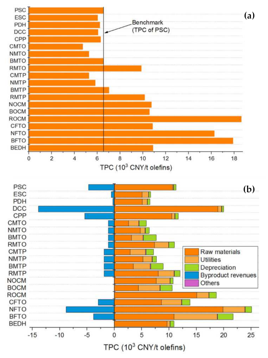
The total production costs (TPCs) for olefin production via different technologies are shown in Figure 2a. According to this analysis, the TPCs of processes including NMTO, CMTO, BMTO, NMTP, CMTP, DCC, CPP, PDH, and ESC were lower than those of steam cracking. The coal-derived methods (CMTO and CMTP) with the lowest TPCs were economically competitive. However, all FTO processes had TPCs higher than the benchmark, although the CFTO method had the lowest TPC among the FTO pathways. The BMTO and BMTP pathways had TPCs close to the benchmark; however, the TPCs of other processes using biomass-derived feedstocks (BOCM, BEDH, and BFTO) were higher than the TPC of steam cracking. Olefin production processes using CO2 as feedstock (RMTO, RMTP, and ROCM) were found to be expensive. Figure 2b shows the individual contribution of different parameters to the TPC of different production methods. The cost of raw material was the main parameter affecting the TPCs in most of the processes. The cost of raw materials in oil-derived technologies, including CCP, DCC, PSC, and PDH, was more than 75% of the TPC. The large byproduct revenues of the oil-derived pathways helped to offset the production costs. The byproduct revenues can offset the TPCs of PSC, CPP, and DCC by 41.9%, 46.3%, and 69.6%, respectively. In NG-derived processes (NFTO, NMTO, NOCM, NMTP, and ESC), the cost of raw materials constituted more than 65% of the TPC. In addition to the raw materials, the cost of utilities was around 13–24% in NG-derived processes. In the CO2-derived processes (RMTO, RMTP, and ROCM) the main cost of the raw material belonged to the cost of hydrogen. In coal- and biomass-derived processes, except for BEDH and CFTO (BMTP, BMTO, BFTO, BOCM, CMTP, and CMTO), the costs of raw materials were around 39–51% of the TCPs. In CFTO and BEDH pathways, 88.6% and 62.4% of TPCs corresponded to the cost of raw materials. The costs of utilities and depreciation were responsible for 27–40% and 12–31% of the TPCs, respectively [14].
Steam cracking is a conventional, well-known process for olefin production, and using SC technology about 40% of the hydrocarbons are converted into olefins [17]. It has been reported that conventional methods, such as the steam cracking of oil and ethane, are the most energy-efficient processes, with about 60 GJ per tons of high-value chemicals (HVCs). The total energy used in methane-based pathways (80 GJ/tHVCs) is about 30% higher than that of conventional steam cracking methods. Coal- and biomass-based processes, with a total energy use of 90–130 GJ/tHVCs, consume about 60–150% more energy than conventional methods [18]. The SC technology, with low CO2 emissions, is one of the best-performing methods for olefin production, and without significant breakthroughs in process intensification, it will not be easy to replace this well-established technology [19]. About 70% of the production cost in a typical naphtha- or ethane-based cracking unit belongs to the cost of the required energy [4], and this high energy demand is due to the endothermic characteristics of the cracking of the C–C bonds of the hydrocarbons [19]. Due to the importance and increasing demand for olefins in chemical industries, this paper discusses the steam cracking process as a well-established technology for olefin production. The cracking furnace, including the radiation section (firebox) and convection section, are explained. The effect of reaction parameters, including the temperature, residence time, the steam-to-hydrocarbon ratio, and the feedstock composition are also described in this paper.
2. Steam Cracking
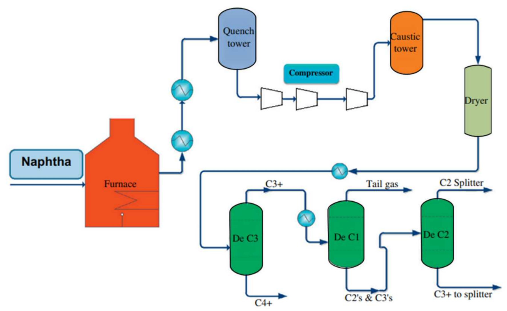
In industry, olefin plants are used for the production of ethylene and propylene, which are the main feedstocks for the production of polyolefins, which account for 50–60% of all commercial organic chemicals [1]. In the steam cracking process, saturated hydrocarbons break into smaller unsaturated hydrocarbons through a reaction with steam. A schematic diagram of the steam cracking process is shown in Figure 3 [20]. The feed for the steam cracking unit can be gaseous or liquid hydrocarbons, such as ethane, propane, butane, naphtha, and gas oil. Butadiene, butylene, aromatics, and benzene-rich pyrolysis gasoline are produced when heavy liquid feeds such as naphtha and gas oils are used as feedstock, whereas methane, ethylene, propylene, and benzene can be produced from any optional feedstocks [21].
The product distribution in steam cracking depends on the composition of the feedstock, the hydrocarbon-to-steam ratio, cracking temperature, and residence time in the furnace. Light olefins, including ethylene and propylene, are produced when light hydrocarbons such as natural gas, ethane, and LPG (propane and butane) are used as the feedstock of the steam cracker unit. The SC process comprises homogeneous pyrolysis in a tube furnace at around 800 °C with a short residence time of around one second [22]. Steam cracking is the leading technology for ethylene production, and was developed in the 1960s. Recent developments have been made to scale up the plants’ size and improve the overall economics; however, its principles have not been changed [23]. The SC process produces a very small percentage of total butene production. The yield of pyrolysis C4 is highly dependent on the type of feedstock. C4 yields of almost 2% and 4% are reported for light hydrocarbon feedstocks, ethane, and propane, respectively, whereas using naphtha and gas oil as the liquid feedstock resulted in around 12% of pyrolysis C4 [24]. Generally, based on the composition of the feedstock and the reaction conditions, the products of steam cracking contain 10–35 wt.% ethylene; 5–20 wt.% propylene; 1–15 wt.% C4 fractions, mainly butadiene and butenes; 1–10 wt.% of aromatics, mainly BTX (benzene, toluene, and xylene); and 0–15 wt.% of heavy hydrocarbons (pyrolysis oils) [6,20,25].
Several successive distillation, refrigeration, and extraction processes are required for product separation. A very low temperature (−114 °C) is required for the demethanization process. Methane and hydrogen are separated at cryogenic temperatures. A large distillation column with 120–180 trays with a high reflux ratio is used for the separation of ethylene and ethane (C2 compounds). Extractive distillation or hydrogenation is used to remove the produced acetylene. Propylene and propane are re-boiled at around 80 °C with the quench water and separated in C3 splitter. The ethylene and propylene refrigeration systems can be operated at low temperatures (between −110 °C and −150 °C) for cooling and high pressure (15–30 bar) for compression. Remaining ethane and propane are recycled as feedstock. Finally, the C4 compounds and aromatic gasoline are separated. The content of paraffins and aromatics of the naphtha (feedstock) can affect the total product yield [6,25].
Similarly to the naphtha steam cracking process, the steam cracking of ethane and other feedstocks also involves three steps—(1) pyrolysis, (2) fractionation and compression, and (3) recovery and separation. These processes can differ in terms of their feedstock compositions and designs/arrangements, and the fractionation and separation sections can also be affected. For example, ethane cracking requires a slightly higher furnace temperature as well as a higher capacity of C2 splitter, but fewer infrastructure facilities are required. In this system, storage tanks or recovery equipment for propylene, butadiene, and BTX aromatics are not required, but it is necessary to have an ethane vaporizer and super-heater [6].
3. Reaction Mechanism
The free radical mechanism was proposed for the decomposition of hydrocarbons in the 1930s [26]. It has been assumed that after decomposition, hydrocarbons are dissociated into two free radicals. The dissociation happens only through the separation of C–C bonds, which have lower strength than the C–H bond, and the breaking of a C–H bond is negligible compared with that of a C–C bond. Paraffin hydrocarbons are decomposed through the breaking of C–C bonds, producing two free radicals. The possibility of the interaction of two dissociated radicals together is very low. The free radicals are able to (1) decompose by breaking into a smaller radical and a compound or creating a compound with the same carbon number as that of the original hydrocarbon by losing a hydrogen atom, or (2) creating a saturated hydrocarbon by taking a hydrogen atom from the surrounding hydrocarbon molecules. For example, methane and hydrogen radicals can be formed when a free methyl radical takes a hydrogen atom from the hydrocarbon molecules. The decomposition of paraffin hydrocarbons involves is a chain of reactions, wherein free radicals or free hydrogen atoms react with a hydrogen atom of the other hydrocarbon molecule. Then, the hydrocarbon radical decomposes into a compound and a hydrogen atom or a smaller free radical, and this cycle is continued excessively. The product’s composition is determined by the chain cycle, and it almost does not depend on the hydrocarbon’s primary composition [23,26]. The simplest free radical mechanism can be observed for ethane cracking, where ethane splits into two methyl radicals in the chain initiation step (Equation (1)). Propagation proceeds via the reaction of an ethane molecule with a methyl radical, resulting in the formation of a methane molecule and an ethyl radical (Equation (2)). The formed ethyl radical can be dissociated into ethylene and hydrogen radicals (Equation (3)). Hydrogen radicals attack another ethane molecules and produce a new ethyl radical and hydrogen molecule (Equation (4)) [1,10,23,26,27,28,29].
Initiation:
Propagation:
etc.
Termination:
etc.
Similarly, the radicals higher than ethyl formed through the reaction of an ethyl radical with an ethylene molecule (Equation (5)) can also dissociate into an ethylene hydrocarbon and a free radical or hydrogen atom. The termination step proceeds via the interaction of two radicals and the formation of saturated or unsaturated molecules (Equations (6)–(11)). Small amounts of heavier hydrocarbons are produced through the termination of the larger radicals formed according to Equation (5) [1,10,23,26,27,28,29].
Compared with gaseous feedstocks, the reaction mechanism for the thermal cracking of heavier alkanes is more complex because there are numerous parallel reactions. In addition to the radical reactions, secondary reactions and other molecular reactions can also take place during the thermal cracking, as below [29,30,31,32]:
- Radical reactions
- (1)
- Chain initiation reactions
- (2)
- Chain propagation reactions
- (3)
- Chain termination reactions
- (4)
- Secondary reactions
- Molecular reactions
- (1)
- Olefin isomerization
- (2)
- Dehydrogenation reaction
- (3)
- Diels—Alder Molecular reaction
- (4)
- Other molecular reactions
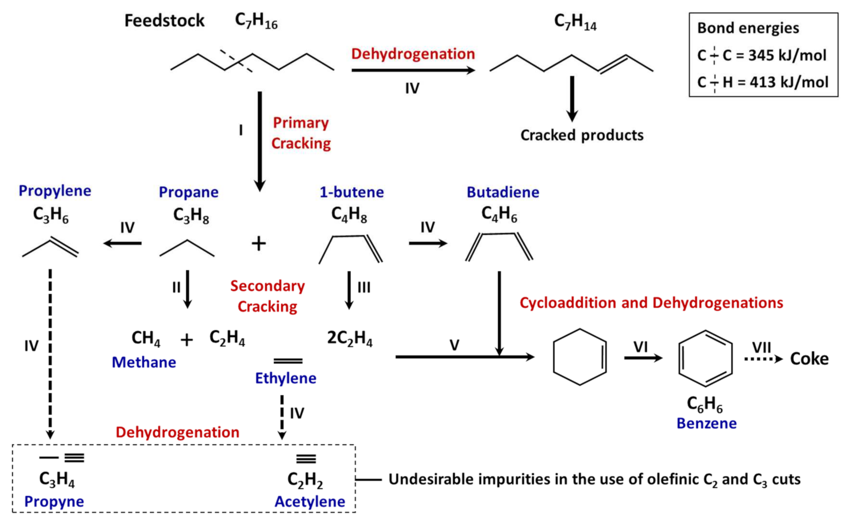
A schematic of the main reactions involved in the cracking of heavier alkanes is shown in Figure 4 [33]. The cracking of heavy alkanes into smaller alkanes is the main reaction, and these reactions create the primary cracking network (reaction I). In the next step, the products of the primary cracking go through secondary reactions (reactions II and III), resulting in the formation of light products that are rich in olefins, and the yield and composition of these products depend on the operating conditions.
The dehydrogenation of olefins (reaction IV) can result in the formation of highly unsaturated products such as acetylene, which are known to be undesired impurities in C2 and C3 olefinic cuts, which show noticeable chemical reactivity. Heavy products can be formed via the Diels and Alder reaction or cycloaddition (reaction V). Aromatic hydrocarbons and particularly benzene are formed if the compounds formed through the cycloaddition are subjected to an intense dehydrogenation process (reaction VI). These are the natural precursors of condensed polyaromatic materials, which, according to their solid-state or pasty, are known as tar and coke (reaction VII) [1,23,26,33,34,35].
Coke formation is observed during the cracking of lighter alkanes; however, its amount is lower than that formed during the cracking of heavier alkanes. Decoking in different parts of the cracking unit is required regularly. For the decoking process, the furnace must be shut down first, then high-pressure air and steam are fed into the furnace while it is heated up to about 900 °C (or even up to 1100 °C). Deposited coke on the wall and tubes is burned off or washed away with high-pressure water, or they can be removed mechanically. The decoking process is required every 14–100 days, depending on the type of feedstocks, severity, and coil configuration. Decoking of a naphtha cracking unit is required every 15–40 days, and the process can take 20–40 h [1,6,33].
4. Cracking Furnace
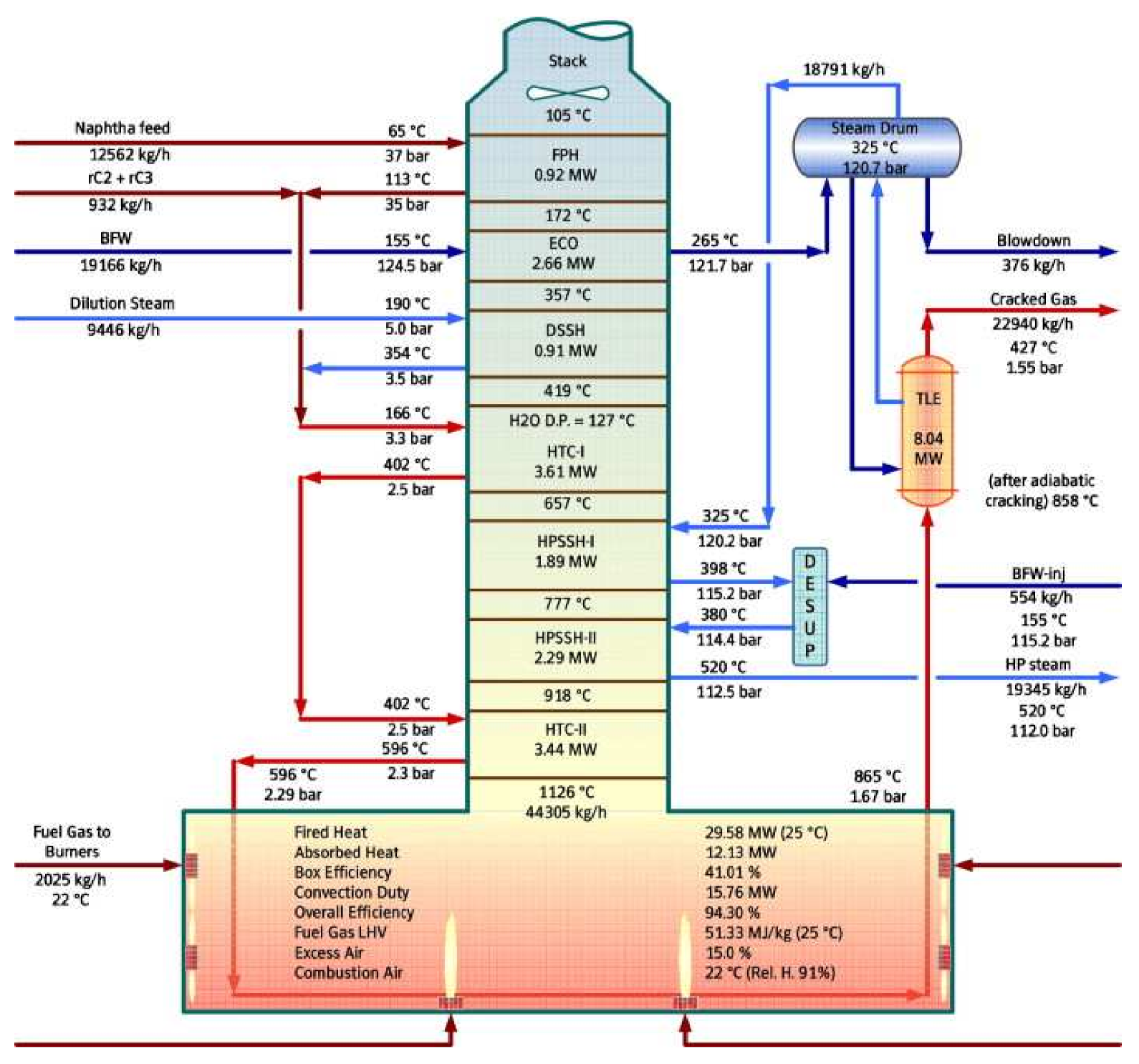
As the heart of the process, the cracking furnace is the crucial factor in the economical and smooth running of the olefin plant. The gas-phase reactions that take place in the cracking furnace are highly endothermic, and the required process heat is supplied from the burners. The furnace consists of a radiation section (firebox), convection section, and stack (Figure 5). The liquid hydrocarbons (such as light and heavy naphtha, gas oil, or preprocessed hydrocracker output products) or gaseous hydrocarbon feedstock (such as ethane, propane, and butane) enters the cracking furnace, where steam and hydrocarbon feed are mixed and preheated in the furnace convection section, and then enters the furnace radiation section. More than 300 million tons of CO2 per year are emitted from steam cracking units [19]. Using green energy, reducing coke formation, and improving the heat transfer in the radiation section can help to reduce CO2 emissions [19]. Depending on the feedstock, the preheating temperature is 500–680 °C [23,32,36,37]. The preheated mixture then enters a fired tubular reactor and is heated up to 850 °C, under a controlled residence time, temperature profile, and partial pressure [36].
Inside the reactor tube, at the short residence time of 0.1–0.5 s, hydrocarbons in the feedstock are cracked into smaller molecules, mostly ethylene, propylene, and di-olefins [23]. The thermal conditions of the firebox are severe, and the temperature of the reactor skin or wall is 850–1100 °C, and the energy content of the hot gas stream leaving this section is recovered. Due to the harsh reaction conditions, in addition to common alloys (such as HK-40, HP-40 NB, and HP-40 WNB), the reactor tubes are also made from special materials such as Inconel 600 (nickel-chromium alloy) with high resistance to carburization, corrosion, and heat. In order to prevent the breakdown of the reactor coil, there is usually an upper limit on the tube wall temperature. The reactor effluent must be cooled down quickly to avoid further cracking of the products via the secondary reactions and decreasing the yield of main products. The cooling process is performed in a closely installed transfer line exchanger (TLE), where the temperature of the gas stream is decreased rapidly from 800–850 °C to 400–500 °C within 0.02–0.1 s. The cracking products are then separated into the desired cuts using a complex sequence of separation and chemical-treatment steps [23,36,37].
4.1. Convection Section
The feedstock (gas or liquid) enters the cracking furnace, and before entering the radiation section, the steam and hydrocarbon feed are mixed and preheated in the convection section. One function of steam dilution is increasing the temperature and thermal energy of the feedstock. Steam is also used for the feed dilution and for decreasing the feed’s partial pressure inside the cracking coils, consequently reducing the carbonization rate and coke formation inside the reactor tube walls [20,34,37]. Otherwise, the high temperature of the cracking process would result in a higher rate of coke formation. The deposition of cokes inside the tube’s wall results in a higher pressure drop, thus a higher partial pressure of hydrocarbons and a higher rate of coke formation. This phenomenon could also impede the heat transfer, which may increase the temperature of the tube skin above the maximum allowed temperature (around 1040–1150 °C). The ratio of steam to hydrocarbon depends on the feedstock composition. It has been reported that steam-to-hydrocarbon ratios (kgsteam/kghydrocarbon) of 0.25–0.4 for gaseous feeds and 0.5–1.0 for liquid feeds are used in steam cracking processes [32,38]. For example, the ratios of steam to ethane and steam to naphtha are 0.3–0.4 and 0.6–0.7 kgsteam/Kghydrocarbon, respectively [20].
As shown in Figure 5, the tube bank coils’ arrangement in the convection section of a cracking furnace is as follows: (1) the feed preheater (FPH), which is used to preheat the hydrocarbon feed before mixing with steam; (2) the economizer (ECO), for heating up the boiling feed water for TLE; (3) the dilution steam super-heater (DSSH), for superheating the dilution steam for mixing with the hydrocarbon feed; (4) heat transfer coil I (HTC-I), for heating the hydrocarbon feed and steam; (5) high-pressure steam superheater I (HPSSH-I), for superheating of the high-pressure steam; (6) high-pressure steam superheater II (HPSSH-II), for further superheating of the steam; and (7) heat transfer coil II (HTC-II), which is the last step in heating the steam and hydrocarbon feed before entering the radiant section [32].
The mixture of the feed and steam is preheated in the convection section of the furnace via convective heat exchange against the hot flue gases leaving the radiant section. About 50% of the heat from flue gases is recovered in the convection section, including 35.5% for the process heat duty, which is the required energy for preheating of the feedstock and dilution steam to the incipient cracking temperature, and about 16% for the utility heating duty, which is the required energy for heating of the high-pressure boiler feed water (BFW) from 110 °C to 180 °C before entering the TLE and to superheat the saturated high-pressure steam produced in the TLEs. The mixture of feed and steam enters the reactor tube in the radiation section, and the cracking reactions occur inside the reactor tube. The flue gas temperature at the stack was observed to be above 400 °C, whereas due to the waste heat recovery in the modern and upgraded plants, the temperature of flue gases at the stack has decreased to less than 100 °C [23,25,32,36,37].
One of the crucial issues in the convection section is the cleaning of the coils, which affects the performance of the furnace. A significant flue gas heat loss to the environment can be caused by fouled tube banks. The temperature of the flue gas at the furnace stack could be increased by gradual fouling over time and also because of the increased thermal load from higher plant rates than those in the original design. Thus, it is required to keep the stack flue gases as cool as possible through periodical maintenance and coil cleaning. Coil fouling may take place on both inside and outside surfaces. The incomplete combustion and soot deposition on the tube could result in fouling on the outside surfaces. The fouling inside the surface could be caused by the deposition of coke inside the tubes; increasing the temperature of hydrocarbon feed above the cracking temperature also results in coke deposition [25,32,36,37]. Because of the tight arrangements of the tube banks and close spacing of adjacent coil services, cleaning the convection section is very difficult [32]. Regular inspection and maintenance of coils is required to maintain the furnace efficiency and avoid decreasing the furnace’s effectiveness. Thermal degradation of liquid feedstock was reported to be the main reason for the deposition of coke on the tube wall, and because of the impingement of droplets, the deposition of coke is mainly observed in inlet-bend, and the complete evaporation of the heavy feedstocks can eliminate coke formation. Coke formation in the inlet-bend could also be reduced by decreasing the droplet size of the spray feed flow at the inlet of the superheater [39].
4.2. Radiation Section
Combustion reactions occur in the radiation section of the furnace. Radiation is the main mechanism for heat transfer to the reactor tubes, which hang in the center of the radiation (firebox) section. The standard industrial designed heights and widths of the radiation section are up to 15 m and 2–3 m, respectively. Firing can be carried out with floor- or wall-mounted radiant burners (or a combination of both), which use fuel gas or a combination of liquid and gas fuel. In order to provide the flames for heating the reactor tubes, fuel and air are mixed and flow into the burners [23,32]. The pressure in the firebox is slightly negative, and the flue gas flows upward [23]. The combustion process requires fuel, air, or oxygen, and ignition to occur. Water vapor, carbon dioxide, nitrogen, and oxygen from the excess air are the main combustion products. At air or oxygen concentrations lower than the required stoichiometric values, a long smoky flame containing some poisonous carbon monoxide could be generated due to incomplete combustion. The incomplete combustion could also result in coke formation inside the tubes and flame impingement and the formation of hot spots on the furnace tubes. Thus, to avoid incomplete combustion, excess air is fed to the burners [32]. It is worth mentioning that the addition of too much air results in the formation of a very bright flame, reducing the heat of combustion. The analysis of flue gas in the stack can help to control the ratio of air to fuel as an important parameter in combustion [23,32].
The length of the firebox is determined by the total production rate and the residence time of the cracking. The required number of radiant coils could be between 16 and 128 coils per furnace, depending on the residence time, furnace design, and capacity. Short residence times require a higher number of individual coils, rather than longer residence times, for the same production capacity, which is due to the differences in the length of the short-residence-time and long-residence-time coils. Long-residence-time coils can have a length of 60–100 m per coil, and the length of short-residence-time coils can be 10–16 m per coil. Depending on the feedstock, the length of the tubes also varies in the range of 45–90 m. For example, the required number of coils for a specific ethylene capacity is defined by the radiant coil surface, which is around 10–15 m2 per ton of feedstock for liquid feedstocks. The production rate per coil can be determined according to its length, diameter, and charge rate, which translates into a certain heat flux on the radiant coil [23,32].
The geometry of the tube reactor depends on the type of feedstock. Fixed-diameter tubes are applied for gaseous feedstocks (ethane, propane, and butane), and for heavier liquid feedstocks such as gasoline and naphtha, multi-diameter tubes are used. This selection process for the tubes is attributed to the higher possibility of coke formation in the liquid cracking process and a higher pressure drop along the reactor. The reactor performance is affected by the configuration of pyrolysis coils. The design of these coils requires comprehensive kinetics, according to the radical mechanism, and a precise description of hydrodynamics and heat transfer. There are some optimization software packages, such as CRACSIM, SPYRO, and PYROSIM, which belong to the main ethylene producer companies. SPYRO, developed by KTI/Technip, is able to simulate and optimize the pyrolysis reactions of the cracking process inside the firebox, with the feedstocks in the range of ethane to gasoline. SPYRO was used to design most of the ethylene plants licensed by KTI/Technip [32].
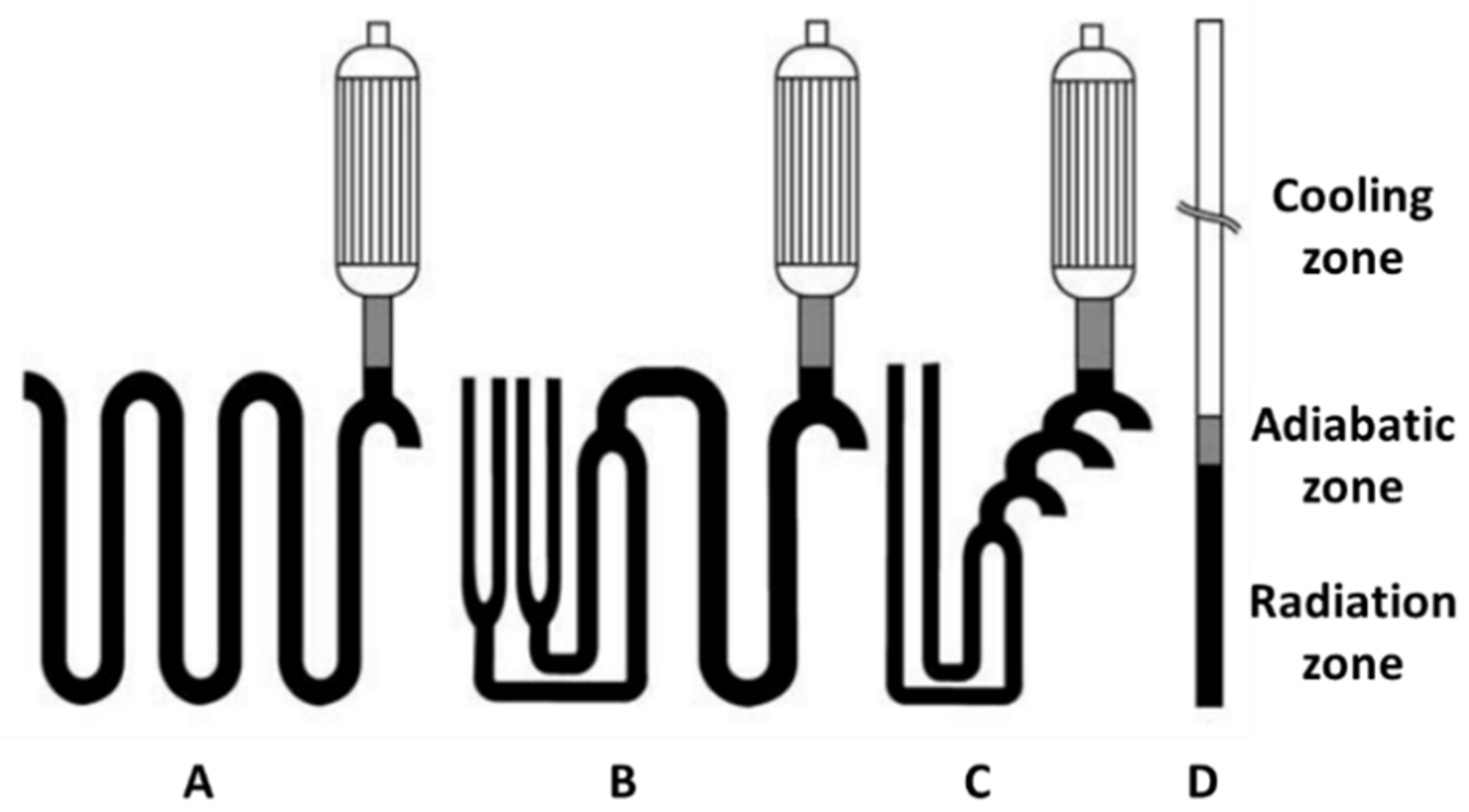
In addition to the radiant coils, cracking reactions also occur in the subsequent heat-insulate transfer line, the nearly-adiabatic zone, and TLE [40]. Belohlav et al. [40] used four different cracking coils for the kinetic model optimization (Figure 6), including (A) long single-row coils, with fixed-diameter tubes, which is usually used for gaseous feeds; (B) and (C) split coils, which are typical reactors with a short residence time of 0.2–0.8 s, with multi-diameter tubes, which are used for liquid hydrocarbons; and (D) short single-row tubes with residence times less than 0.1 s [32,40]. The yield of ethylene in the modelled reactors (according to the type of cracking reactor), according to the reactor designs shown in Figure 6, are given in Table 2.
At a high temperature in the adiabatic zone, the yield of ethylene increases slightly, and as a result of condensation reactions at a lower temperature, the ethylene yield decreases in the cooling zone. The adiabatic transfer line is defined as a straight tube with a specified inner and outer diameter, length, and construction steel. The reactor tubes inside the furnace receive heat flux from the burners installed on the floor and/or the wall of the furnace. The transfer line exchangers of the rectors with short residence times are modeled as a simple long tube with a millisecond residence time and as cones with back-to-back bundles of 244–366 short tubes [40].
4.3. Furnace Draft
The required pressure difference in the furnace, called the draft or draught, can be induced through different methods, including natural draft, forced draft, induced draft, and balanced draft methods [32,41,42]. Natural draft is utilized in many burners in refinery and petrochemical process heater services. In the natural draft, the density of the inlet air decreases due to the heat in the furnace, and gases flow naturally through the stack and cause a pressure drop which is normally negative, and it is typically less than 25 mm (1 in) in the water column at the burner location. This negative pressure in the furnace depends on the temperature and height of the radiant firebox and the level of the draft at the top of the radiant firebox. This negative pressure results in the flowing of fresh air at the air doors around the burners. Sometimes, an induced draft (ID) fan can enhance the natural draft [41]. Induced draft systems utilize a fan at the stack inlet to pull the gases out of the furnace. The fan could be appropriately designed to handle the high gas temperature. However, a significant amount of energy from the flue gases is removed in the upstream convection section, and the temperature of gases reaching the ID fan should not be very high.
Another method for producing draft in the furnace is the forced draft (FD) system, in which a fan is used to provide a combustion oxidizer stream (usually air) to the burners at a positive pressure. Air doors and a stack damper control the FD system. Due to the increased turbulent mixing in the flame at a higher level of the pressure drop, the flame dimensions can be significantly smaller. In addition, the oxygen combustion stream can be controlled over a wider range of heat release. The combustion efficiencies can be improved and operated with low excess oxygen over a wider range of fuel input at this improves mixing and enhances control conditions [32,41,42].
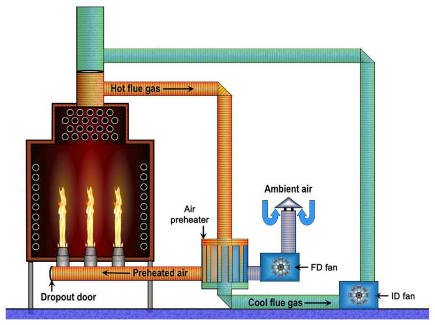
Balanced draft is a combination of ID and FD and is sometimes referred to as pull/push or FD/ID method (Figure 7). This system is used to increase the energy efficiency of a combustion process by preheating the combustion air. Ambient air and the exhaust (or flue gas) enter the air preheater, and the energy from the hot exhaust gas is transferred to the air. The temperatures of preheated air are in the range of 320–540 °C. However, higher preheat temperatures can result in considerably higher rate of NOx formation. The two fans in the balanced draft system supply the forced draft to the burners and pull the gases out of the furnace via the induced draft. Changes in weather conditions (e.g., wind direction) do not affect the balanced draft, whereas the other three types of draft (natural, induced, and forced drafts) can be affected [32,41].
5. Effects of Operating Parameters on Olefin Yields
Various parameters need to be considered to optimize a pyrolysis reactor for the production of ethylene and propylene. These parameters are included temperature, residence time, steam-to-hydrocarbon ratio, and feedstock composition [32]. A higher reaction temperature results in a higher yield of ethylene, a shorter residence time, and higher reaction velocities. A low operating pressure is preferred for this process because of the gas phase reaction inside the reactor tubes and the production of more gaseous molecules for its reactions to the right. The reactor pressure must be kept as low as possible (between 170 and 250 kPa). The gas pressure in the reactor tube outlet is indirectly adjusted by the suction process gas pressure of the compressor in the compression section, downstream of the process. As mentioned earlier, to reach lower hydrocarbon pressures, process steam is co-fed with the hydrocarbon feed to reduce the hydrocarbon partial pressure and lower coke deposition. The addition of steam decreases the partial pressure of the hydrocarbon feed and favors the formation of primary products [23,32].
5.1. Temperature
Owing to the endothermic nature of the reactions, the reactor temperature needs to be kept as high as 900 °C on the reactor exit. The arrangement of the burners inside the firebox affects the heat flux and the temperature distribution on the reactor wall. It is worth noting that the coke formation inside the reactor tubes is increased by increasing the reactor temperature, resulting in the carbonization of the tube, therefore decreasing the furnace run length and the tube lifetime. Lower temperatures favor the formation of secondary products via oligomerization reactions; thus, it is necessary to apply an optimum temperature profile along the coil to avoid long residence times at low temperatures. Fired tubular reactors are mainly used in commercial pyrolysis units for ethylene production, in which the temperature of the reactants increases continuously from the inlet (500–680 °C) to the outlet (775–875 °C) of the reactor coils. In modern cracking furnaces, a rapid heating system is used at the inlet of the radiant coils, and the temperature rises quickly to the required reaction temperature. However, due to the low temperature, the reaction rate constants are low. In the middle of the coil, the rate of increasing the temperature is lower, but the cracking rates are significantly higher. Owing to the endothermic characteristics of the reaction, most of the heat is transferred to the mixture. At the coil outlet, the rate of the temperature rise increases again, though it is lower than the rate of the temperature rise in the inlet of the coil [23].
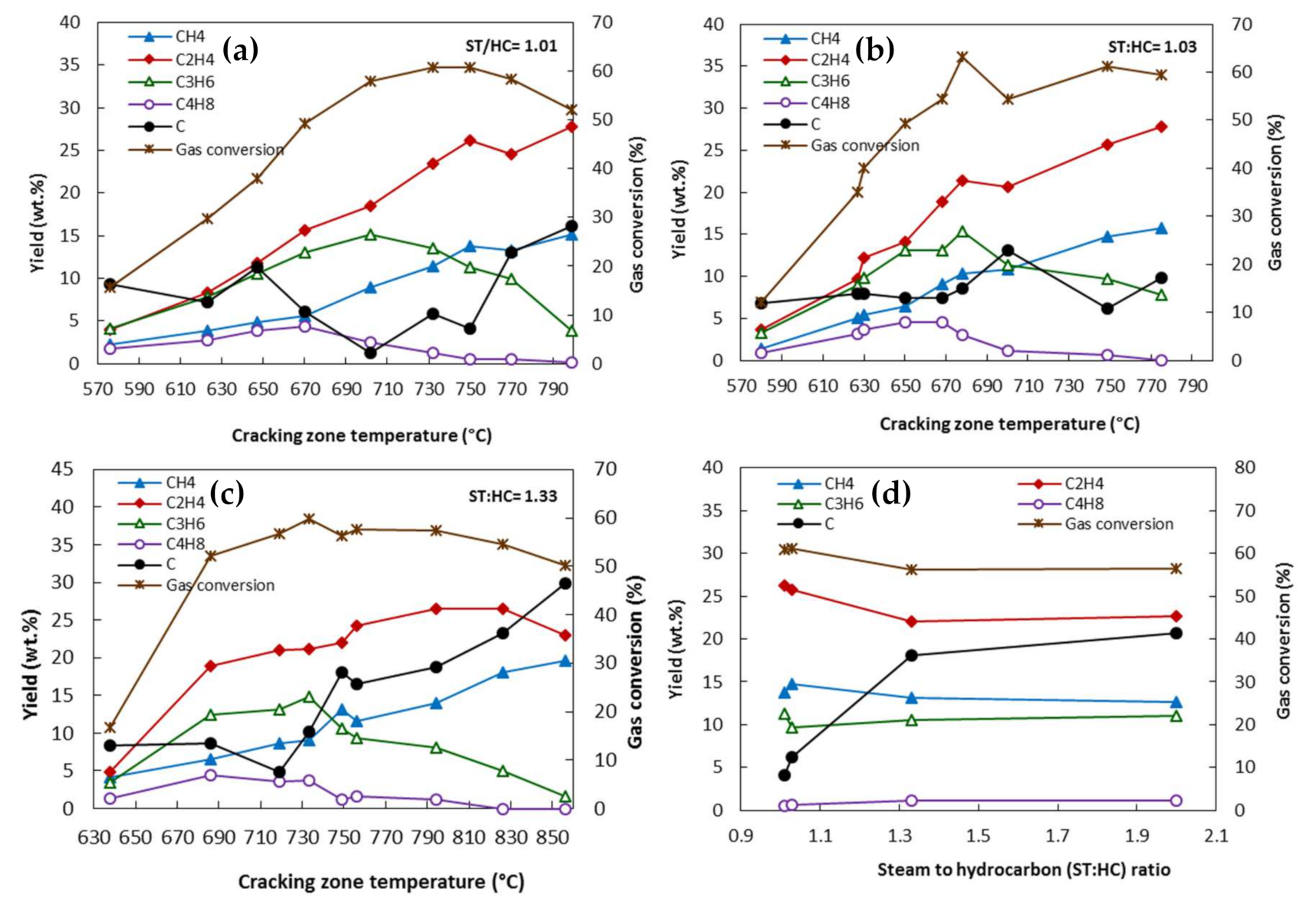
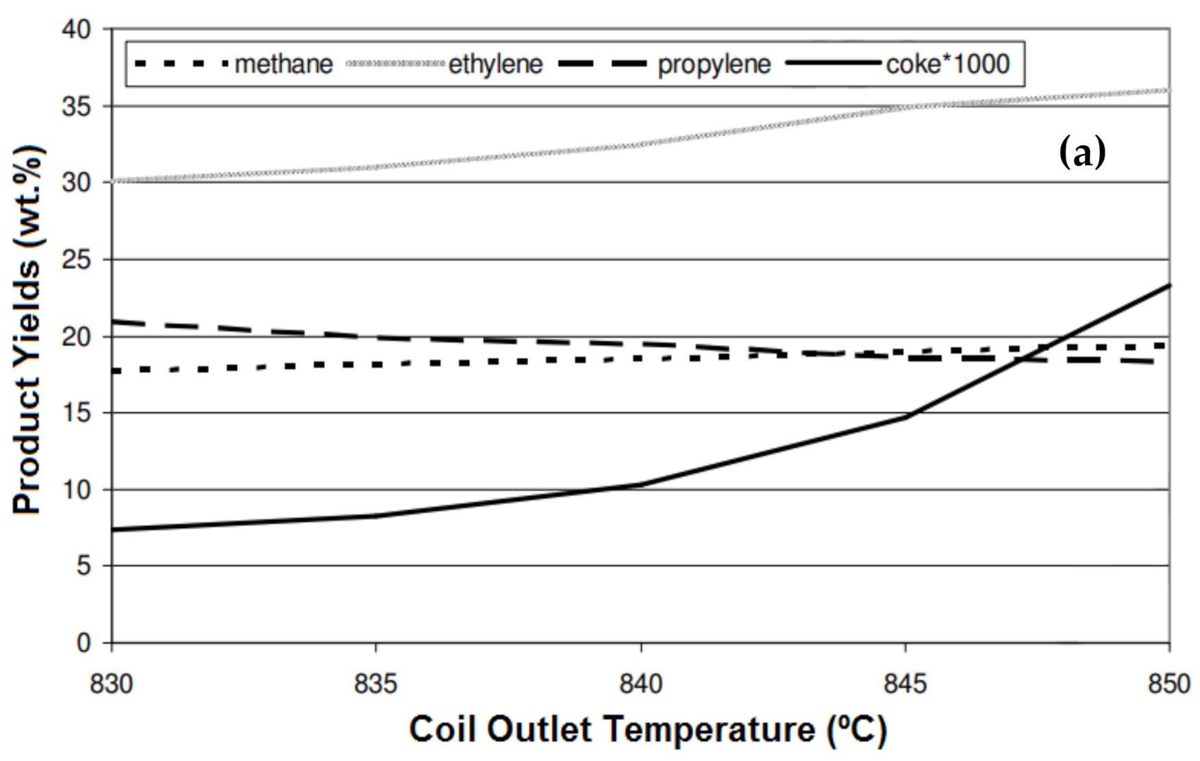
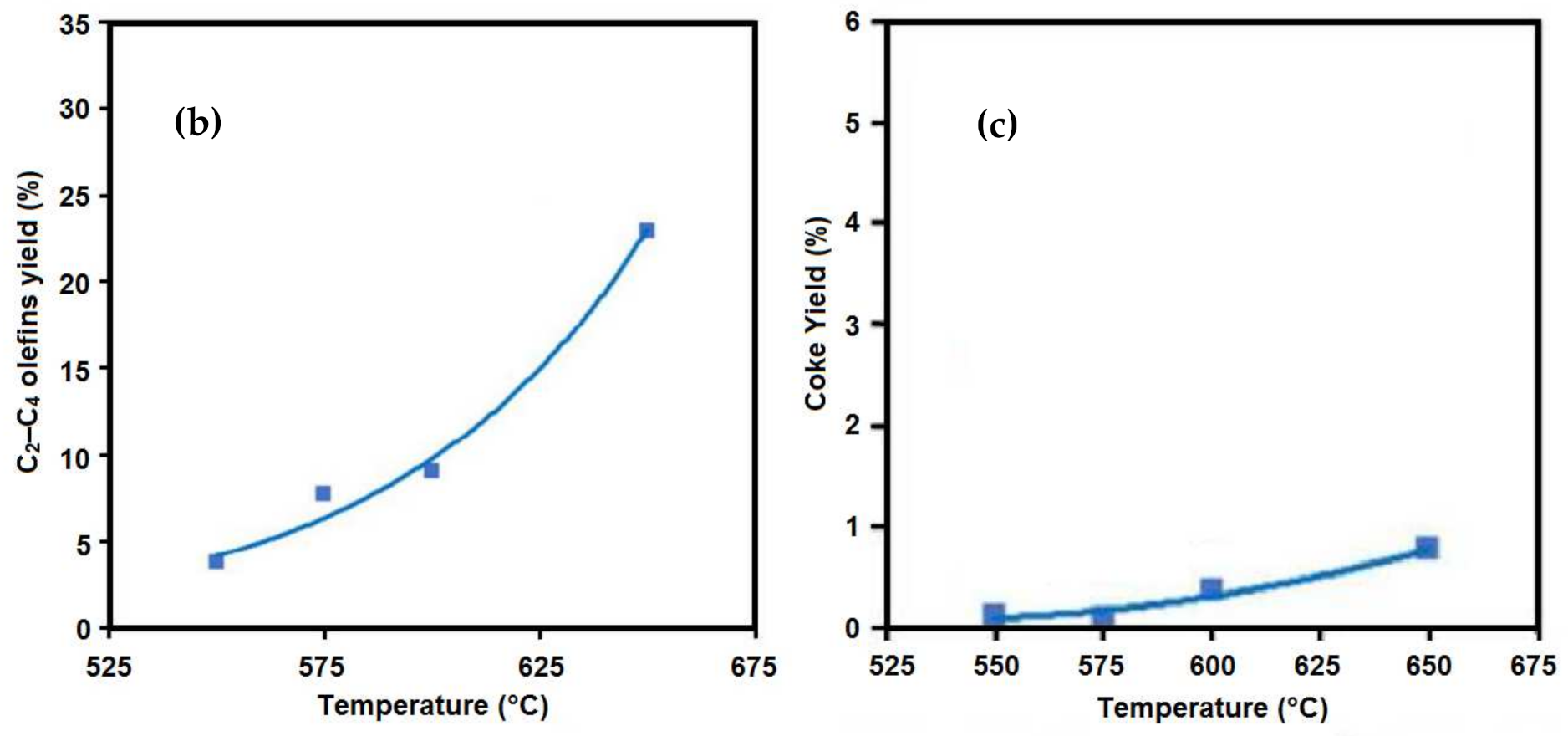
The effects of different operating conditions, including temperature, the steam-to-hydrocarbon ratio (atmospheric gas oil), and residence time, on the yield of the products, were investigated by Depeyre et al. [43]. As shown in Figure 8a–c, regardless of the steam-to-hydrocarbon ratio, the yields of methane and ethylene increased with the increasing of the temperature, whereas the yields of propylene and butenes reached a maximum and then decreased at higher temperatures. For the different steam-to-hydrocarbon ratios, the highest gas conversion was obtained at about 750 °C. The ratio of the total weight of the produced gas per weight of the injected gas oil used as feedstock is referred to as gas conversion. The amount of deposited carbon also increases with temperature. It has been reported that both radical reactions and molecular secondary reactions are involved in the reaction; however, in a higher-temperature reaction (above 750 °C), the molecular reactions are the dominant reactions. Gál and Lakatos [44] studied the effect of coil outlet temperature (COT) on the product yields and variation in the coke formation rate, using natural gas as a feedstock for the steam cracking process. They reported that by increasing the COT from 830 °C to 845 °C, the ethylene yield increased from 30% to 35%, and increasing the temperature above 845 °C did not cause a considerable increase in the yield (Figure 9a). The yields of methane and propylene showed little changes when changing the temperature from 830 °C to 845 °C. Interestingly, the coke formation increased significantly (from 7% to 23%) when increasing the temperature.
Al-Absi and Al-Khattaf [45] reported that the conversion in thermal cracking is a function of contact time and temperature during the cracking of Arabian Light (AL) crude oil. Increasing the temperature from 550 °C to 650 °C resulted in a sharp increase in the C2–C4 olefin yield from 3.8 wt.% to 22.9 wt.% (Figure 9b). The main drawback of high-temperature cracking is the rapid coke formation and carburization, resulting in a shorter lifetime of the reactor tube. The important reactions for coke formation are di- and poly-alkenes, the cyclization of alkenes, aromatization, and condensation. Polyaromatic compounds formed via these reactions are the main source of coke during the reaction. Similarly to the results of other reports, coke formation during the cracking of AL crude oil also increased when increasing the temperature (Figure 9c). However, nowadays, engineers are trying to develop new technologies to reduce coke formation and to use better metallurgy to endure the high temperatures.
Che et al. [46] performed the thermal cracking of a vacuum residue to investigate the product distribution at different temperatures and a steam-to-hydrocarbon weight ratio of 0.6. By increasing the temperature from 600 °C to 700 °C, the conversion increased from 90.67% to 93.97% (Table 3). Due to the stronger bond breaking at the higher temperatures, the gas yield also increased gradually with temperature. The yield of C2–C4 olefins increased by 47% (from 17.71% to 18.73%) when the temperature increased from 600 °C to 700 °C. The olefinicity (weight ratio of unsaturated open-chain hydrocarbons with at least one double bond, including C2, C3, and C4 olefins, in the cracked gas) of 53–67% confirmed that alkenes are the main components in the gaseous products. Increasing the temperature enhanced the intensity of condensations, and consequently the coke yield increased.
5.2. Residence Time
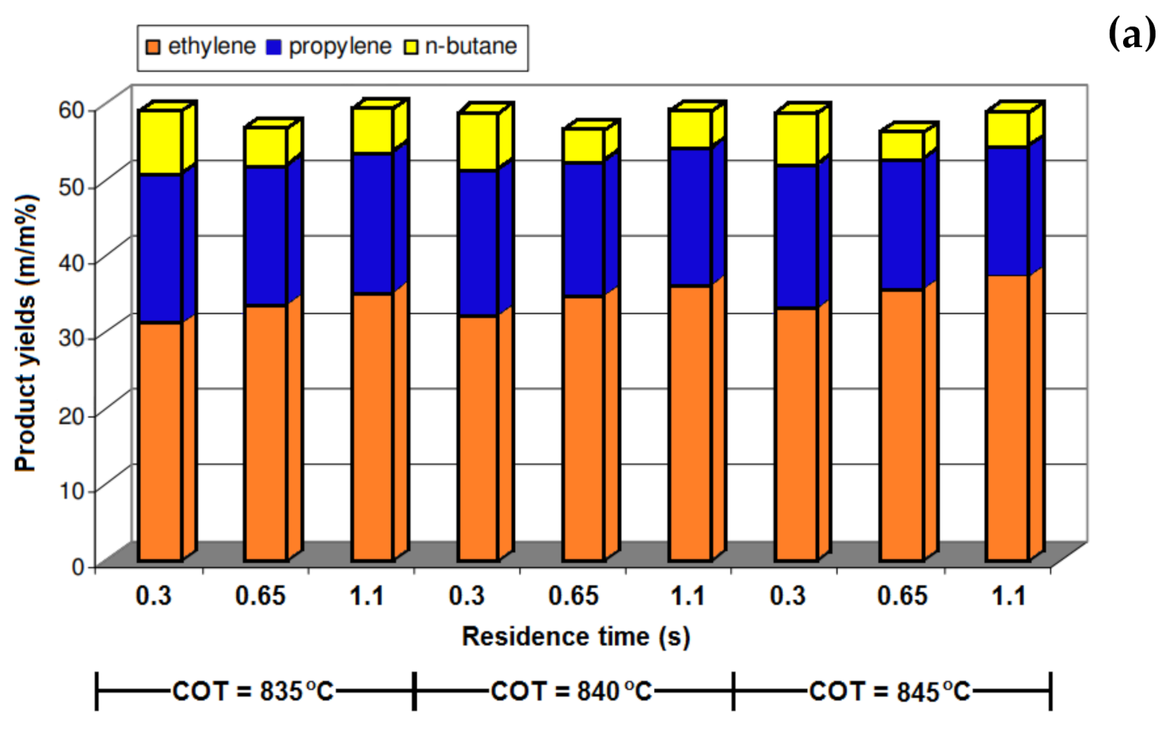
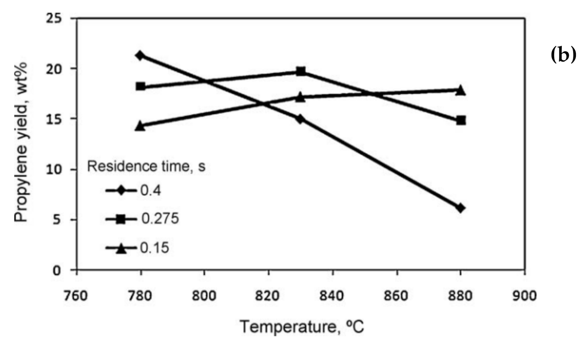
The other operating parameter is residence time, which can be measured based on the initial contact between the heat source and feedstocks to the time of product quenching [47]. The produced olefins could be degraded to the lower-value long-chain hydrocarbons due to the occurrence of a multitude of side reactions. A long residence time favors secondary reactions, whereas the yield of the primary products such as ethylene and propylene increases at a short residence time [23]. These side reactions need to be minimized by designing the coils to have a very short residence time and through the rapid cooling of the product gas mixture after it leaves the reactor coil. Old reactors, constructed between 1940 and 1960, had horizontal tubes with a residence time of more than 0.5 s. The reactor tube diameter needs to be decreased to reduce the residence time [32]. In modern reactors, the residence time is controlled by the tube diameter and reactor flow rate, and they have a residence time of 0.08–0.25 s. A lower residence time could be obtained by decreasing the tube diameter. Gál and Lakatos [44] reported that the conversion of n-butane was increased by increasing the residence time from 0.3 s to 0.65 s and 1.1 s (Figure 10a). The same trend was also observed for the ethylene yield, and compared with the yield at a residence time of 0.3 s, it was 7% and 11.1% higher at the residence times of 0.65 s and 1.1 S, respectively. The coke formation also significantly increased at a higher residence time, and it was 21% and 32% higher at 0.65 s and 1.1 s, respectively. The effect of temperature, residence time, and the steam-to-hydrocarbon ratio on the yield of light olefins in naphtha steam cracking was investigated by Keyvanloo et al. [48]. It was observed that at the short residence time of 0.15 s, the yield of propylene increased when increasing the temperature (Figure 10b). At a lower reaction temperature, the yield of propylene was higher with a longer residence time, whereas by increasing the reaction temperature, the longer residence time resulted in the formation of secondary reactions and the yield of propylene decreased.
In a study by Han et al. [49], the influence of the residence time of the yield of light olefins in the steam cracking of a mixture of waste oil and naphtha was studied. By increasing the residence time from 0.3 s to 0.4 s, the yield of ethylene increased, whereas a further increase in the residence time resulted in a decrease in the total yield of C2–C4 light olefins. Raw materials have sufficient time for the reaction at longer residence times (up to 0.4 s); however, as mentioned earlier, the secondary reactions also start to occur at longer residence times, resulting in a lower gas yield and higher coke formation. The effect of residence time was more prominent on the yield of ethylene than that of propylene and butadiene. In another study by Karaba et al. [50], the effect of residence time on the product distribution of the steam cracking process at 815 °C was evaluated. In this study, a mixture of 10 wt.% FT vacuum residue and 90 wt.% hydrocracked vacuum distillate (HCVD) was used as the feedstock. The shorter residence time resulted in higher yields of ethylene and propylene, whereas the yields of ethane, benzene, toluene, and oil decreased (Table 4). Sedighi et al. [30] also reported that an increase in the residence time led to a higher rate of ethylene formation, whereas the propylene yield decreased. Accurate control of residence times and temperature are crucial to avoid secondary reactions while still allowing the maximum cracking of the feedstock.
5.3. Steam-to-Hydrocarbon Ratio
The ratio of steam to hydrocarbon feedstock is another parameter that needs to be considered during the cracking reaction. Steam and feedstock are mixed and preheated in the convection section of the cracking furnace to vaporize the liquid feedstock [51]. The steam-to-hydrocarbon ratio (ST:HC) depends on the feedstock type and is controlled between 0.3 and 0.7 on a weight basis. Steam is used as an inert that is premixed with the feed to reduce the partial pressure of the hydrocarbons, therefore reducing the coke formation and carbonization rates. The temperature and thermal energy of the feedstock also increase with the addition of steam. The ST:HC ratio is around 0.3 kgsteam/Kghydrocarbon for the lighter gaseous feeds, such as ethane, and increases to 0.6 kgsteam/Kghydrocarbon for the heavier hydrocarbons, such as naphtha and gas oil [32]. It is important to have an optimum ratio of steam to hydrocarbon to avoid negative effects on product yields and reduce the specific energy consumption of the production unit. The influence of the steam-to-hydrocarbon ratio in the steam cracking of natural gas was studied by Gál and Lakatos [44], and the basic value for ST:HC was considered to be 0.5 in that study. Their results (Table 5) showed that reducing the ST:HC ratio up to 10% did not significantly affect the product yields, but a shorter reaction time was expected due to the higher coke formation. A further decrease in the ST:HC ratio (up to 30%) resulted in a decrease in the ethylene formation and increased the coke formation. By reducing the ST:HC ratio at both 835 °C and 840 °C, methane formation showed a rising trend.
The product distribution in the thermal cracking of atmospheric gas oil at 800 °C and a residence time of 0.4 s was studied by Abghari et al. [52]. It was found that by increasing the ST:HC ratio, the yield of methane and ethylene decreased, whereas the propylene yield did not change much. Similarly, a study on the effect of the steam-to-gas-oil ratio in a cracking reaction at 750 °C (Figure 8d) revealed that the partial pressure of hydrocarbons was reduced via steam dilution; the gas conversion and the yields of methane and ethylene were decreased, whereas the coke formation increased [43]. In another study by Sedighi et al. [30,53], the effect of the steam-to-hydrocarbon ratio on the product yields in the steam cracking of heavy liquid hydrocarbon (at 843 °C and a residence time of 0.17 s) was studied, and it was reported that the yields of methane and ethylene increased when increasing the ST:HC ratio, whereas propylene yield decreased slightly. The evaluation of the effect of the ST:HC ratio on the product distribution in the steam cracking of a mixture of waste oil and naphtha by Han et al. [49] revealed that the yield of light olefins reached a maximum when increasing the ratio from 0.42 to 0.65, then decreased when increasing the ST:HC ratio up to about 0.9. Increasing the ratio above 0.9 did not significantly affect the yields, and they remained unchanged. At constant total pressure, a more diluted feedstock (higher ST:HC ratio) with a lower partial pressure of hydrocarbon results in a higher rate of ethylene formation.
Ethane steam cracking in an industrial tubular reactor was modeled and optimized by Jiang et al. [35]. By increasing the steam-to-ethane ratio, the selectivity to ethylene increased from 69% to 82%, whereas at the same time, the conversion of ethane decreased from 74% to 55%. The optimum ratio of steam to ethane was found to be in the range of 0.3 to 0.4 in order to obtain the highest ethylene yield. Increasing the steam-to-ethane ratio from 0 to 1.0 resulted in a 46% decrease in coke formation (from 0.0092 to 0.0042 kg/(h.m2)). It is important to operate at the optimum steam-to-hydrocarbon ratio to achieve the highest possible yields of light olefins and an acceptable coke formation rate.
5.4. Feedstock Composition
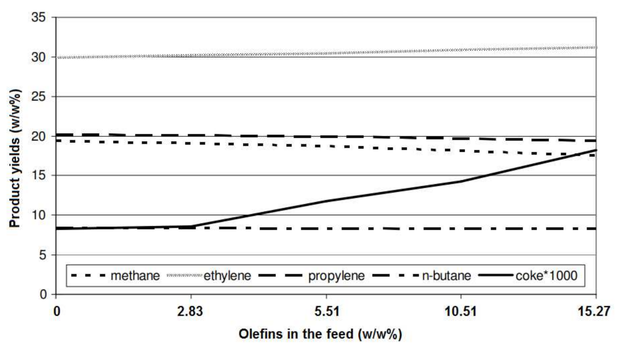
The product yield can be affected by the feed composition. This effect is more pronounced in the re-pyrolysis of recycled cracked gases, which can be mixed with the fresh hydrocarbons, and may contain a large amount of olefins and di-olefins. Gál and Lakatos [44] reported that the yield of methane and propylene slightly decreased by increasing the presence of olefins in the feedstock (Figure 11); lower olefin concentration resulted in lower coke formation. The ethylene yield increased gradually by increasing the presence of unsaturated hydrocarbons in the feedstock. The dependency of product yields and the type of feedstock was studied by Dominov et al. [54]. The product distribution is changed by varying the feedstock composition. It can be seen that by changing the feedstock from ethane to propane and butane and liquid feedstocks, the ethylene yield decreased by more than 40%, whereas the yield of heavier olefins increased. The feedstocks of ethylene plants usually contain straight and branched alkanes, olefins, aromatics, and naphthenes.
Olefins are produced mainly from alkanes and naphthenes in the feedstock. The higher concentration of n-alkanes leads to a higher ethylene yield, and alkanes with even numbers of carbon atoms result in a slightly higher ethylene yields than those with odd numbers of carbon atoms. The yield of propene decreases when increasing the chain length of hydrocarbons in the feedstock [23]. Compared with n-alkanes, the presence of isoalkanes results in lower ethylene and propene yields and produces higher amounts of hydrogen, methane, C4, and higher olefins. Simple and aromatic ring compounds, such as benzene, are formed during the cracking process and remain unchanged under normal cracking conditions.
Zimmermann and Walzl [23] provided a comprehensive investigation of the production of ethylene through steam cracking using different gaseous and liquid feedstocks, including ethane, propane, butane, naphtha, gas oil (atmospheric gas oil (AGO)), and hydrocracker residue (hydrocracker residue (HCR) or heavy vacuum gas oil (HVGO). The effect of residence time on the product distribution was also reported. The ratio of steam to hydrocarbon (ST:HC) was increased by changing the feedstock from light hydrocarbon (ethane) to heavier feedstocks, as follows: ethane, propane (ST:HC = 0.3) < butane (ST:HC = 0.35) < low-severity naphtha, P/E = 0.65 kg/kg (ST:HC = 0.4) < medium-severity naphtha, P/E = 0.55 kg/kg (ST:HC = 0.45) < high-severity naphtha, P/E = 0.45 kg/kg (ST:HC = 0.5) < AGO, P/E = 0.54 kg/kg (ST:HC = 0.8) < AGO, P/E = 0.53 kg/kg (ST:HC = 1.0). When ethane was used as the feedstock, the coil inlet temperature was in the range of 650–680 °C, and the conversion was 60–75% in commercial furnaces. A typical conversion of 90–93% was reported for the propane cracking in the furnace, and conversion increased to 94–96% when using butane as the feedstock. Reducing the residence time resulted in the lower formation of methane and the higher formation of ethylene. Due to the presence of a large amount of condensed polynuclear aromatics in gas oil, heavier products (C5+) were formed using AGO as the cracking feedstock. During the cracking process, these aromatic components remained unchanged or condensed to other molecules with a higher molecular mass. HCR, the residue of the hydrocrackers, which are working at severe operating conditions, is a highly saturated product with a low content of aromatics and polyaromatics. The yield of ethylene using the HCR or HVGO is almost similar to naphtha cracking (~26%) [23].
The product distribution in the thermal cracking of different types of crude oil was evaluated by Al-Absi et al. [55]. The crude oils with different API gravities of 34° (Arab Light: AL), 39° (Arab Extra Light: AXL), and 51° (Arab Super Light: ASL) were used as the cracking feedstock. A lower API gravity indicates a heavier crude with a higher density. The density of the selected feedstocks at 15 °C were in the following order: AL (892 kg/m3) > AXL (828 kg/m3) > ASL (774 kg/m3). The paraffin, isoparaffin, olefin, naphthene, and aromatic (PIONA) contents of the naphtha fraction of these crude oils were: 34/32/0/19/15 wt.%, 34/31/0/8/27 wt.%, and 46/18/0/9/27 wt.% for ASL, AXL, and AL, respectively. There was a linear relationship between the conversion of the feedstocks and temperature and this was increased by increasing the temperature (Table 6).
The conversions of all feedstocks were about 14% at 600 °C and the highest conversion (32.8%) belonged to the heaviest feedstock (AL) at 650 °C. Similarly to the conversion, the yield of C2–C4 olefins increased by increasing the temperature. The ethylene formation obeyed the free radical and beta-scission mechanisms. At higher temperatures, the cleavage of C–C bond uncharged molecules resulted in the formation of very reactive free radicals. These free radicals undergo beta-scission and produce ethylene and primary free radicals. The yields of propylene and butenes also followed the same trend as ethylene and increased when increasing the temperature [55].
The effect of feedstock composition on the product distribution in the steam cracking process, as studied by Geerts et al. [56], also revealed that the steam cracking of the naphtha fraction resulted in higher yields of ethylene and propylene (36%) than the yields of these products (28.3%) obtained from the steam cracking of wide-range gas oil (WRGO). However, the yields of pyrolysis fuel oil (PFO) and pyrolysis gasoline (Pygas) were higher when WRGO was used as the feedstock. The pyrolysis of light and heavy naphtha feedstocks and their mixtures was evaluated by Karaba et al. [57]. It was reported that the product distribution depended on the feedstock’s properties, and light naphtha could lead to higher yields of the light olefins. Pyrolysis of the feedstock containing 20–60 wt.% of heavy naphtha resulted in a higher ethylene yield (around 1.1 wt.% higher), whereas the addition of light naphtha to the heavy naphtha feedstock caused a decrease in the yields of methane, C4 hydrocarbons, and benzene (Figure 12). Even this slight increase in the ethylene yield could make a significant improvement at the industrial scale. For example, for an ethylene plant with 30 tons per hour of naphtha feedstock, this 1.1 wt.% increase in the ethylene yield results in an additional 330 kg of ethylene per hour per one steam cracker, which means about 300 EUR per hour per one steam cracker [57].
Zámostný et al. [58] studied the pyrolysis of feedstocks with different hydrocarbon chain lengths at 810 °C, 400 kPa, and residence times of 0.2–0.4 s in the reaction zone. They found that longer-chain hydrocarbons with a higher number of carbon atoms showed a higher probability of the hydrogen abstraction reaction; thus, the hydrogen transfer rate could increase and result in a higher conversion rate. The feedstock conversion increased from 78% for n-pentane to 99% for n-hexane. The yield of ethylene also increased for longer hydrocarbon chains because despite the original position of the unpaired electron in the formed radicals, they can produce more ethylene molecules through the successive-beta scission of C–C bonds. However, in very-long-chain hydrocarbons, the beta-scission of C–H bonds could interrupt the beta-scission of the C–C bonds and result in the increased formation of 1-alkene. Due to the more evident effect of alkyl radicals with odd carbon numbers produced during the cracking process, the yield of propylene and methane decreased when increasing the chain length [58].
Recently, the effect of normal/cyclo-alkane in the product distribution of hydrocarbon pyrolysis was studied by Hou et al. [59]. Pyrolysis of n-hexane, n-heptane, cyclohexane, and methylcyclohexane was performed at 650–830 °C, under atmospheric pressure. The molecular structures could determine the initial cleavage of C–C bonds and the formation of radicals, which affect the hydrogen abstraction, beta-scission, secondary cracking, radical combination aromatization, and Diels–Alder reactions in the pyrolysis process. The direct cleavage of C–C bonds and the production of alkyl radicals were observed for the n-hexane feedstock, while cyclohexane with the cyclic structure with the consecutive reactions of ring-opening, isomerization, and decomposition led to the formation of alkyl and alkenyl radicals. A lower conversion and a higher selectivity to 1,3-butadiene and aromatics were observed in the pyrolysis of cyclohexane. Similarly to the results reported by Zámostný et al. [58], a longer hydrocarbon chain length weakened the C–C bonds and thus increased the number of free radicals, resulting in higher conversion and selectivity to heavier products. A demethylation reaction was observed in the presence of the methyl substituent, which can improve the formation of radicals (methyl, cycloalkyl, and methylcycloalkyl). A higher conversion rate was obtained with the pyrolysis of methylcyclohexane than with cyclohexane. Pyrolysis of the mixture of n-hexane and cyclohexane revealed that the formation of radicals and hydrogen abstraction were decreased by increasing the cyclohexane content. Due to the competition of cyclohexane and n-hexane for the radicals in hydrogen abstraction, the n-hexane decomposition could be suppressed with a higher content of cyclohexane [59].
6. Conclusions
Olefins are critical components in chemical industries and, depending on the feedstock’s properties, they are produced using different pathways, such as thermal cracking, fluid catalytic cracking, the conversion of methanol to olefins, Fischer–Tropsch synthesis, and oxidative coupling of methane. However, thermal cracking, which occurs in a cracking furnace, is the main industrial process for the production of light olefins. This review discussed the cracking mechanism, the cracking furnace, and the effect of different operating parameters on the product distribution. According to studies of the effect of different reaction parameters on olefin yields, it can be concluded that the maximum yield of olefins can be obtained by providing these conditions: (1) a higher coil outlet temperature, (2) a short residence time in the radiant coil, (3) low partial pressure of hydrocarbons, which can be achieved through the addition of steam, (4) highly saturated feedstock, and (5) faster quenching of the cracked gases. The process involving cracking reactions under these conditions also minimizes the yield of methane and aromatic components with high molecular mass.
Author Contributions
Conceptualization, Z.G.; writing—original draft preparation, Z.G. and F.G.; writing—review and editing, Z.G., F.G., Z.T. and M.V. All authors have read and agreed to the published version of the manuscript.
Funding
This publication is a result of the project which was carried out within the financial support of the Ministry of Industry and Trade of the Czech Republic with institutional support for long-term conceptual development of research organization. The result was achieved using the infrastructure included in the Efficient Use of Energy Resources Using Catalytic Processes (LM2018119) project, which has been financially supported by MEYS within the targeted support of large infrastructures.
Conflicts of Interest
The authors declare no conflict of interest.
References
- Hsu, C.S.; Robinson, P.R. Petroleum Science and Technology; Springer International Publishing: Cham, Switzerland, 2019. [Google Scholar]
- Speight, J.G. (Ed.) Organic Chemistry. In Environmental Organic Chemistry for Engineers; Butterworth-Heinemann: Oxford, UK, 2017; Chapter 2; pp. 43–86. [Google Scholar] [CrossRef]
- Fakhroleslam, M.; Sadrameli, S.M. Thermal Cracking of Hydrocarbons for the Production of Light Olefins; A Review on Optimal Process Design, Operation, and Control. Ind. Eng. Chem. Res. 2020, 59, 12288–12303. [Google Scholar] [CrossRef]
- Deloitte. The Future of Petrochemicals: Growth Surrounded by Uncertainty. 2019. Available online: https://www2.deloitte.com/content/dam/Deloitte/us/Documents/energy-resources/us-the-future-of-petrochemicals.pdf (accessed on 28 June 2021).
- Blay, V.; Louis, B.; Miravalles, R.; Yokoi, T.; Peccatiello, K.A.; Clough, M.; Yilmaz, B. Engineering zeolites for catalytic cracking to light olefins. ACS Catal. 2017, 7, 6542–6566. [Google Scholar] [CrossRef]
- Ren, T.; Patel, M.; Blok, K. Olefins from Conventional and Heavy Feedstocks: Energy use in Steam Cracking and Alternative Processes. Energy 2006, 31, 425–451. [Google Scholar] [CrossRef] [Green Version]
- Amghizar, I.; Vandewalle, L.A.; Van Geem, K.M.; Marin, G.B. New Trends in Olefin Production. Engineering 2017, 3, 171–178. [Google Scholar] [CrossRef]
- Dugkhuntod, P.; Wattanakit, C. A Comprehensive Review of the Applications of Hierarchical Zeolite Nanosheets and Nanoparticle Assemblies in Light Olefin Production. Catalysts 2020, 10, 245. [Google Scholar] [CrossRef] [Green Version]
- Akah, A.; Williams, J.; Ghrami, M. An Overview of Light Olefins Production via Steam Enhanced Catalytic Cracking. Catal. Surv. Asia 2019, 23, 265–276. [Google Scholar] [CrossRef]
- Alotaibi, F.M.; González-Cortés, S.; Alotibi, M.F.; Xiao, T.; Al-Megren, H.; Yang, G.; Edwards, P.P. Enhancing the Production of Light Olefins from Heavy Crude Oils: Turning Challenges into Opportunities. Catal. Today 2018, 317, 86–98. [Google Scholar] [CrossRef]
- Roudgar Saffari, P.; Salarian, H.; Lohrasbi, A.; Salehi, G. The Numerical Simulation of Olefin Production Furnace for Pollution Reduction: Two Case Studies. Gas Process. J. 2021, 9, 15–32. [Google Scholar] [CrossRef]
- Depeyre, D.; Flicoteaux, C.; Chardaire, C. Pure n-hexadecane Thermal Steam Cracking. Ind. Eng. Chem. Process Des. Dev. 1985, 24, 1251–1258. [Google Scholar] [CrossRef]
- Bender, M. An Overview of Industrial Processes for the Production of Olefins—C4 Hydrocarbons. ChemBioEng Rev. 2014, 1, 136–147. [Google Scholar] [CrossRef]
- Zhao, Z.; Jiang, J.; Wang, F. An Economic Analysis of Twenty Light Olefin Production Pathways. J. Energy Chem. 2021, 56, 193–202. [Google Scholar] [CrossRef]
- Gholami, Z.; Gholami, F.; Tišler, Z.; Tomas, M.; Vakili, M. A Review on Production of Light Olefins via Fluid Catalytic Cracking. Energies 2021, 14, 1089. [Google Scholar] [CrossRef]
- Alabdullah, M.; Rodriguez-Gomez, A.; Shoinkhorova, T.; Dikhtiarenko, A.; Chowdhury, A.D.; Hita, I.; Kulkarni, S.R.; Vittenet, J.; Sarathy, S.M.; Castaño, P.; et al. One-Step Conversion of Crude Oil to Light Olefins using a Multi-Zone Reactor. Nat. Catal. 2021, 4, 233–241. [Google Scholar] [CrossRef]
- Zacharopoulou, V.; Lemonidou, A.A. Olefins from biomass intermediates: A review. Catalysts 2018, 8, 2. [Google Scholar] [CrossRef] [Green Version]
- Ren, T.; Patel, M.K. Basic Petrochemicals from Natural Gas, Coal and Biomass: Energy use and CO2 Emissions. Resour. Conserv. Recycl. 2009, 53, 513–528. [Google Scholar] [CrossRef]
- Amghizar, I.; Dedeyne, J.N.; Brown, D.J.; Marin, G.B.; Van Geem, K.M. Sustainable Innovations in Steam Cracking: CO2 Neutral Olefin Production. React. Chem. Eng. 2020, 5, 239–257. [Google Scholar] [CrossRef]
- Seifzadeh Haghighi, S.; Rahimpour, M.R.; Raeissi, S.; Dehghani, O. Investigation of ethylene production in naphtha thermal cracking plant in presence of steam and carbon dioxide. Chem. Eng. J. 2013, 228, 1158–1167. [Google Scholar] [CrossRef]
- Garg, A. Fired Heaters-Key to Efficient Operation of Refineries and Petrochemicals; HarbisonWalker International: Sugar Land, TX, USA, 2017. [Google Scholar]
- Subramanian, R.; Schmidt, L.D. Renewable Olefins from Biodiesel by Autothermal Reforming. Angew. Chem. Int. 2005, 44, 302–305. [Google Scholar] [CrossRef]
- Zimmermann, H.; Walzl, R. Ethylene. In Ullmann’s Encyclopedia of Industrial Chemistry; Wiley: Weinheim, Germany, 2009. [Google Scholar] [CrossRef]
- Geilen, F.M.A.; Stochniol, G.; Peitz, S.; Schulte-Koerne, E. Butenes. In Ullmann’s Encyclopedia of Industrial Chemistry; Wiley: Weinheim, Germany, 2014; pp. 1–13. [Google Scholar] [CrossRef]
- Moreira, J.V. Steam Cracking: Kinetics and Feed Characterisation; Instituto Superior Tecnico: Lisbon, Portugal, 2015; pp. 1–10. Available online: https://fenix.tecnico.ulisboa.pt/downloadFile/1126295043834327/JVM_ExtendedAbstract.pdf (accessed on 3 February 2021).
- Rice, F.O. The Thermal Decomposition of Organic Compounds from the Standpoint of Free Radicals. I. Saturated Hydrocarbons. J. Am. Chem. Soc. 1931, 53, 1959–1972. [Google Scholar] [CrossRef]
- Van Goethem, M.W.M. Next Generation Steam Cracking Reactor Concept. Ph.D. Thesis, Technical University of Delft, Delft, The Netherlands, 2010. [Google Scholar]
- Moulijn, J.A.; Makkee, M.; van Diepen, A.E. Chemical Process Technology, 2nd ed.; John Wiley & Sons: Oxford, UK, 2013. [Google Scholar]
- Depeyre, D.; Flicoteaux, C. Modeling of Thermal Steam Cracking of n-hexadecane. Ind. Eng. Chem. Res. 1991, 30, 1116–1130. [Google Scholar] [CrossRef]
- Sedighi, M.; Keyvanloo, K.; Towfighi, D.J. Olefin Production from Heavy Liquid Hydrocarbon Thermal Cracking: Kinetics and Product Distribution. Iran. J. Chem. Chem. Eng. 2010, 29, 135–147. [Google Scholar] [CrossRef]
- Dente, M.; Ranzi, E.; Goossens, A.G. Detailed Prediction of Olefin Yields from Hydrocarbon Pyrolysis Through a Fundamental Simulation Model (SPYRO). Comput. Chem. Eng. 1979, 3, 61–75. [Google Scholar] [CrossRef]
- Sadrameli, S.M. Thermal/Catalytic Cracking of Hydrocarbons for the Production of Olefins: A State-of-the-Art Review I: Thermal cracking review. Fuel 2015, 140, 102–115. [Google Scholar] [CrossRef]
- Chauvel, A.; Lefebvre, G. Petrochemical Processes 1. In Synthesis-Gas Derivatives and Major Hydrocarbons, 2nd ed.; Editions Technip Paris: Paris, France, 1989. [Google Scholar]
- Van Goethem, M.W.M.; Barendregt, S.; Grievink, J.; Moulijn, J.A.; Verheijen, P.J.T. Model-based, Thermo-Physical Optimisation for High Olefin Yield in Steam Cracking Reactors. Chem. Eng. Res. Des. 2010, 88, 1305–1319. [Google Scholar] [CrossRef]
- Jiang, B.-B.; Liao, Z.-W.; Mohsin, A.; Sun, J.-Y.; Wang, J.-D.; Yang, Y.; Yang, Y.-R. Modeling and Optimization of Ethane Steam Cracking Process in an Industrial Tubular Reactor with Improved Reaction Scheme. China Petrol. Process. Petrochem. Technol. 2020, 22, 117–125. [Google Scholar]
- Karimzadeh, R.; Godini, H.R.; Ghashghaee, M. Flowsheeting of Steam Cracking Furnaces. Chem. Eng. Res. Des. 2009, 87, 36–46. [Google Scholar] [CrossRef]
- Variny, M.; Mierka, O.; Gašparovič, L. Experiences and Future Prospects of GRUCON—SLOVNAFT Cooperation in Energy Auditing Field. In Proceedings of the 42nd International Conference of SSCHE, Tatranské Matliare, Slovakia, 25–29 May 2015; Slovak Society of Chemical Engineering: Bratislava, Slovakia, 2015; pp. 351–358. [Google Scholar]
- Marcos, J.M.M. Modelling of Naphtha Cracking for Olefins Production. Master’s Thesis, Technical University of Lisbon, Lisbon, Portugal, 2016. Available online: https://fenix.tecnico.ulisboa.pt/downloadFile/563345090415270/Thesis_Joao_Marcos_73026.pdf (accessed on 17 April 2021).
- Mahulkar, A.V.; Heynderickx, G.J.; Marin, G.B. Simulation of the Coking Phenomenon in the Superheater of a Steam Cracker. Chem. Eng. Sci. 2014, 110, 31–43. [Google Scholar] [CrossRef]
- Belohlav, Z.; Zamostny, P.; Herink, T. The Kinetic Model of Thermal Cracking for Olefins Production. Chem. Eng. Process. 2003, 42, 461–473. [Google Scholar] [CrossRef]
- Baukal, C.E.; Vaccari, M.; Claxton, M.G. Chapter 20—Burners for Reformers and Cracking Furnaces. Comput. Aided Chem. Eng. 2019, 45, 937–984. [Google Scholar] [CrossRef]
- Wang, Q.; Xu, H.; Pan, L.; Sun, L. Active Disturbance Rejection Control of Boiler Forced Draft System: A Data-Driven Practice. Sustainability 2020, 12, 4171. [Google Scholar] [CrossRef]
- Depeyre, D.; Flicoteaux, C.; Arbabzadeh, F.; Zabaniotou, A. Modeling of Thermal Steam Cracking of an Atomspheric Gas Oil. Ind. Eng. Chem. Res. 1989, 28, 967–976. [Google Scholar] [CrossRef]
- Gál, T.; Lakatos, B.G. Thermal Cracking of Recycled Hydrocarbon Gas-Mixtures for Re-Pyrolysis: Operational Analysis of Some Industrial Furnaces. Appl. Therm. Eng. 2008, 28, 218–225. [Google Scholar] [CrossRef]
- Al-Absi, A.A.; Al-Khattaf, S.S. Conversion of Arabian Light Crude Oil to Light Olefins via Catalytic and Thermal Cracking. Energy Fuels 2018, 32, 8705–8714. [Google Scholar] [CrossRef]
- Che, Y.; Hao, J.; Zhang, J.; Qiao, Y.; Li, D.; Tian, Y. Vacuum Residue Thermal Cracking: Product Yield Determination and Characterization Using Thermogravimetry–Fourier Transform Infrared Spectrometry and a Fluidized Bed Reactor. Energy Fuels 2018, 32, 1348–1357. [Google Scholar] [CrossRef]
- Hulet, C.; Briens, C.; Berruti, F.; Chan, E.W. A Review of Short Residence Time Cracking Processes. Int. J. Chem. React. Eng. 2005, 3, 1–74. [Google Scholar] [CrossRef]
- Keyvanloo, K.; Towfighi, J.; Sadrameli, S.M.; Mohamadalizadeh, A. Investigating the Effect of Key Factors, Their Interactions and Optimization of Naphtha Steam Cracking by Statistical Design of Experiments. J. Anal. Appl. Pyrolysis 2010, 87, 224–230. [Google Scholar] [CrossRef]
- Han, L.; Ding, C.Q.; Lui, H. Studies on Olefin Production by Steam Cracking of Waste Oil Blended with Naphtha. Appl. Mech. Mater. 2013, 291, 738–743. [Google Scholar] [CrossRef]
- Karaba, A.; Rozhon, J.; Patera, J.; Hájek, J.; Zámostný, P. Fischer-Tropsch Wax from Renewable Resources as an Excellent Feedstock for the Steam-Cracking Process. Chem. Eng. Technol. 2021, 44, 329–338. [Google Scholar] [CrossRef]
- Abbasali, S.M.Z.; Farsi, M.; Rahimpour, M.R. Simulation and Dynamic Optimization of an Industrial Naphtha Thermal Cracking Furnace Based on Time Variant Feeding Policy. Chem. Prod. Process Model. 2018, 13, 1–15. [Google Scholar] [CrossRef]
- Abghari, S.Z.; Darian, J.T.; Karimzadeh, R.; Omidkhah, M.R. Determination of Yield Distribution in Olefin Production by Thermal Cracking of Atmospheric Gasoil. Korean J. Chem. Eng. 2008, 25, 681–692. [Google Scholar] [CrossRef]
- Sedighi, M.; Keyvanloo, K.; Towfighi, J. Experimental Study and Optimization of Heavy Liquid Hydrocarbon Thermal Cracking to Light Olefins by Response Surface Methodology. Korean J. Chem. Eng. 2010, 27, 1170–1176. [Google Scholar] [CrossRef]
- Dominov, P.; Gilyazetdinova, R.; Zhirnov, B.; Tarasov, I.; Khlestkin, R. Overview world technologies of pyrolysis and perspective of development. Electron. Sci. J. Oil Gas Bus. 2009, 1, 23–32. Available online: http://ogbus.ru/files/ogbus/eng/authors/Dominov/Dominov_1.pdf (accessed on 29 January 2021).
- Al-Absi, A.A.; Aitani, A.M.; Al-Khattaf, S.S. Thermal and Catalytic Cracking of Whole Crude Oils at High Severity. J. Anal. Appl. Pyrolysis 2020, 145, 104705. [Google Scholar] [CrossRef]
- Geerts, M.; Ristic, N.; Djokic, M.; Ukkandath Aravindakshan, S.; Marin, G.B.; Van Geem, K.M. Crude to Olefins: Effect of Feedstock Composition on Coke Formation in a Bench-Scale Steam Cracking Furnace. Ind. Eng. Chem. Res. 2020, 59, 2849–2859. [Google Scholar] [CrossRef]
- Karaba, A.; Dvořáková, V.; Patera, J.; Zámostný, P. Improving the Steam-Cracking Efficiency of Naphtha Feedstocks by Mixed/Separate Processing. J. Anal. Appl. Pyrolysis 2020, 146, 104768. [Google Scholar] [CrossRef]
- Zámostný, P.; Bělohlav, Z.; Starkbaumová, L.; Patera, J. Experimental Study of Hydrocarbon Structure Effects on the Composition of its Pyrolysis Products. J. Anal. Appl. Pyrolysis 2010, 87, 207–216. [Google Scholar] [CrossRef]
- Hou, X.; Ma, Z.; Chen, B.; Zhang, J.; Ning, Y.; Zhao, L.; Yuan, E. Role of normal/cyclo-alkane in hydrocarbons pyrolysis process and product distribution. J. Anal. Appl. Pyrolysis 2021, 156, 105130. [Google Scholar] [CrossRef]
Figure 1.
Different technologies for olefin production, reproduced from [6].
Figure 1.
Different technologies for olefin production, reproduced from [6].

Figure 2.
(a) Total production costs of different olefin production technologies, (b) a detailed breakdown of the TPCs of different production pathways [14].
Figure 2.
(a) Total production costs of different olefin production technologies, (b) a detailed breakdown of the TPCs of different production pathways [14].

Figure 3.
Simplified block diagram for the typical steam cracking process [20].
Figure 3.
Simplified block diagram for the typical steam cracking process [20].

Figure 4.
Main reactions involved in the cracking of higher alkanes, reproduced from [33].
Figure 4.
Main reactions involved in the cracking of higher alkanes, reproduced from [33].

Figure 5.
Thermal cracking furnace in a typical olefin plant [36].
Figure 5.
Thermal cracking furnace in a typical olefin plant [36].

Figure 6.
Schematic representation of cracking reactor designs used for kinetic model optimization by Belohlav et al. [40].
Figure 6.
Schematic representation of cracking reactor designs used for kinetic model optimization by Belohlav et al. [40].

Figure 7.
Schematic representation of a balanced draft system [41].
Figure 7.
Schematic representation of a balanced draft system [41].

Figure 8.
Effect of temperature at different steam-to-hydrocarbon (ST:HC) mass ratios (a) ST:HC = 1.01, (b) ST:HC = 1.03, (c) ST:HC = 1.33; and (d) the effect of ST:HC on the product yields of the thermal steam cracking of an atmospheric gas oil, reproduced from [43].
Figure 8.
Effect of temperature at different steam-to-hydrocarbon (ST:HC) mass ratios (a) ST:HC = 1.01, (b) ST:HC = 1.03, (c) ST:HC = 1.33; and (d) the effect of ST:HC on the product yields of the thermal steam cracking of an atmospheric gas oil, reproduced from [43].

Figure 9.
(a) Effect of coil outlet temperature on the product yields [44]; (b) effect of temperature on light olefin yield; and (c) coke formation for the cracking of Arabian Light crude oil using thermal cracking [45].


Figure 10.
(a) Effect of residence time on the product yields [42], (b) effect of residence time on the propylene yield (steam-to-oil ratio = 0.5 g/g) [48].


Figure 11.
Effect of the olefin concentration in the feedstock on product yields [44].
Figure 11.
Effect of the olefin concentration in the feedstock on product yields [44].

Figure 12.
Potential product yield increases (T: 810 °C, P: 4 bar, F: 65 Nml/min) depending on the content of heavy naphtha in the blend with light naphtha [57].
Figure 12.
Potential product yield increases (T: 810 °C, P: 4 bar, F: 65 Nml/min) depending on the content of heavy naphtha in the blend with light naphtha [57].


Table 1.
Description and attributes of conversion pathways [14].
Table 1.
Description and attributes of conversion pathways [14].
| No. | Process | Feedstock | Main Products |
|---|---|---|---|
| 1 | Steam cracking of mixed petroleum (PSC) | Naphtha | Ethylene, propylene |
| 2 | Steam cracking of ethane (ESC) | Ethane | Ethylene |
| 3 | Propane dehydrogenation (PDH) | Propane | Propylene |
| 4 | Catalytic pyrolysis process of heavy oil (CPP) | Atmospheric residuum | Ethylene, propylene |
| 5 | Deep catalytic cracking of heavy oil (DCC) | Wax oil | Propylene |
| 6 | Coal gasification produces syngas; methanol is synthesized from syngas and converted into olefins (CMTO) | Coal | Ethylene, propylene |
| 7 | NG reforming produces syngas; methanol is synthesized from syngas and converted into olefins (NMTO) | NG | Ethylene, propylene |
| 8 | Methanol is synthesized from CO2 hydrogenation and converted into olefins (RMTO) | CO2 and H2 | Ethylene, propylene |
| 9 | Biomass gasification produces syngas; methanol is synthesized from syngas and converted into olefins (BMTO) | Bio-waste | Ethylene, propylene |
| 10 | Coal gasification produces syngas; methanol is synthesized from syngas and converted into propylene (CMTP) | Coal | Propylene |
| 11 | NG reforming produce syngas; methanol is synthesized from syngas and converted into propylene (NMTP) | NG | Propylene |
| 12 | Methanol is synthesized from CO2 hydrogenation and converted into propylene (RMTP) | CO2 and H2 | Propylene |
| 13 | Biomass gasification produces syngas; methanol is synthesized from syngas and converted into propylene (BMTP) | Bio-waste | Propylene |
| 14 | Oxidative coupling of methane derived from NG (NOCM) | NG | Ethylene |
| 15 | Oxidative coupling of methane derived from hydrogenation of CO2 (ROCM) | CO2 and H2 | Ethylene |
| 16 | Oxidative coupling of methane derived from biogas (BOCM) | Biomass | Ethylene |
| 17 | Coal gasification produces syngas, and syngas is converted into olefins through FT synthesis (CFTO) | Coal | Ethylene, propylene |
| 18 | NG reforming produces syngas, and syngas is converted into olefins through FT synthesis (NFTO) | NG | Ethylene, propylene |
| 19 | Biomass gasification produces syngas, and syngas is converted into olefins through FT synthesis (BFTO) | Bio-waste | Ethylene, propylene |
| 20 | Ethanol is produced through anaerobic fermentation and converted into ethylene through dehydration (BEDH) | Ethanol | Ethylene |
Table 2.
The yield of ethylene (wt.%) at the outlets of reactor sections for the different reactor types [40].
Table 2.
The yield of ethylene (wt.%) at the outlets of reactor sections for the different reactor types [40].
| Reactor Section | Radiant Coil Type | |||
|---|---|---|---|---|
| A | B | C | D | |
| Radiation zone | 48.1 | 26.3 | 26.8 | 29.2 |
| Adiabatic zone | 48.5 | 27.4 | 29.3 | 30.4 |
| Cooling zone | 47.2 | 27.2 | 29.2 | 31.2 |
Table 3.
Conversion and composition of thermal cracking products of VR [46].
Table 3.
Conversion and composition of thermal cracking products of VR [46].
| Product | Temperature (°C) | ||
|---|---|---|---|
| 600 | 650 | 700 | |
| Conversion (%) | 90.67 | 91.55 | 93.97 |
| Gas yield (wt.%) | 18.92 | 27.38 | 35.32 |
| Gas composition (wt.%) | |||
| Methane | 2.91 | 5.01 | 9.44 |
| Ethylene | 5.76 | 6.92 | 6.66 |
| Propylene | 4.76 | 6.38 | 6.95 |
| Butenes | 2.19 | 4.02 | 5.12 |
| C2–C4 olefins | 12.71 | 17.32 | 18.73 |
| Olefinicity (%) | 67.16 | 63.26 | 53.03 |
| Coke yield (wt.%) | 8.20 | 8.49 | 9.13 |
Table 4.
Effect of residence time on the product yields for the steam cracking of a mixture of 10 wt.% FT residue and 90 wt.% HCVD at 815 °C [50].
Table 4.
Effect of residence time on the product yields for the steam cracking of a mixture of 10 wt.% FT residue and 90 wt.% HCVD at 815 °C [50].
| Products Yields (wt.%) | Residence Time (s) | ||
|---|---|---|---|
| 0.22 | 0.30 | 0.51 | |
| Methane | 4.6 | 6.8 | 8.9 |
| Ethane | 1.6 | 1.8 | 2.6 |
| Ethylene | 32.7 | 30.4 | 28.1 |
| Propane | 0.3 | 0.5 | 0.4 |
| Propylene | 15.8 | 15.3 | 13.7 |
| Acetylene | 0.6 | 0.5 | 0.4 |
| i-butane | 0.0 | 0.0 | 0.0 |
| Propadiene | 0.7 | 0.4 | 0.3 |
| n-butane | 0.0 | 0.1 | 0.1 |
| t-2-butene | 0.3 | 0.3 | 0.3 |
| 1-butene | 6.6 | 3.6 | 1.3 |
| i-butene | 1.5 | 1.5 | 1.2 |
| c-2-butene | 0.3 | 0.4 | 0.3 |
| Propyne | 0.5 | 0.5 | 0.4 |
| 1,3-butadiene | 8.7 | 8.1 | 6.3 |
| Cyclopentadiene + isoprene | 3.6 | 3.2 | 2.8 |
| Benzene | 4.2 | 6.6 | 9.8 |
| Toluene | 2.1 | 3.3 | 4.6 |
| Ethylbenzene | 0.4 | 0.4 | 0.3 |
| Xylenes | 1.3 | 1.8 | 2.6 |
| C5–C6 | 4.6 | 3.5 | 2.2 |
| C7–C12 | 2.9 | 2.9 | 3.0 |
| Oil | 6.6 | 8.2 | 10.3 |
Table 5.
Effect of the steam-to-hydrocarbon ratio on the product yields [44].
Table 5.
Effect of the steam-to-hydrocarbon ratio on the product yields [44].
| COT (°C) | 835 | 840 | 835 | 840 | 835 | 840 | 835 | 840 |
|---|---|---|---|---|---|---|---|---|
| Reduction of ST:HC Ratio | 5% | 5% | 10% | 10% | 20% | 20% | 30% | 30% |
| Products | ||||||||
| Methane | 18.22 | 18.75 | 18.32 | 18.72 | 18.53 | 19.06 | 19.27 | 19.89 |
| Ethylene | 32.22 | 33.73 | 32.97 | 33.18 | 31.78 | 32.25 | 30.46 | 30.87 |
| Propylene | 20.63 | 20.15 | 20.68 | 20.34 | 20.79 | 20.32 | 21.14 | 20.87 |
| Butadiene | 3.97 | 3.85 | 3.97 | 3.89 | 3.98 | 3.86 | 3.64 | 3.57 |
| n-butane (Residual) | 8.74 | 7.58 | 8.72 | 7.88 | 8.68 | 7.56 | 8.64 | 7.54 |
| Benzene + Toluene | 1.61 | 1.63 | 1.71 | 1.74 | 1.81 | 1.89 | 1.98 | 2.05 |
| Coke | 0.0084 | 0.0089 | 0.0091 | 0.0097 | 0.0107 | 0.012 | 0.0128 | 0.015 |
Table 6.
Conversion and yields of product for the thermal cracking of different crude oils [55].
Table 6.
Conversion and yields of product for the thermal cracking of different crude oils [55].
| Feed | ASL | AXL | AL | ||||||
|---|---|---|---|---|---|---|---|---|---|
| Temperature (°C) | 600 | 625 | 650 | 600 | 625 | 650 | 600 | 625 | 650 |
| Conversion (%) | 14.5 | 21.1 | 27.6 | 14.0 | 21.6 | 27.0 | 14.2 | 23.3 | 32.8 |
| Product yield (%) | |||||||||
| H2 | 0.1 | 0.1 | 0.1 | 0.1 | 0.1 | 0.1 | 0.1 | 0.1 | 0.2 |
| C1 | 1.5 | 2.5 | 3.6 | 1.7 | 2.8 | 3.5 | 1.8 | 3.1 | 4.6 |
| 2.6 | 4.1 | 6.1 | 3.1 | 5.0 | 6.5 | 2.8 | 5.1 | 7.6 | |
| 3.1 | 5.0 | 6.8 | 3.4 | 5.5 | 6.9 | 3.2 | 5.7 | 8.6 | |
| 3.4 | 4.9 | 6.0 | 3.2 | 4.6 | 5.6 | 3.0 | 4.7 | 6.7 | |
| 9.1 | 14.0 | 18.9 | 9.7 | 15.1 | 19.0 | 9.0 | 15.5 | 22.9 | |
| / | 1.2 | 1.2 | 1.1 | 1.1 | 1.1 | 1.1 | 1.1 | 1.1 | 1.1 |
| Coke | 0.2 | 0.3 | 0.3 | 0.3 | 0.4 | 0.5 | 0.4 | 0.6 | 0.8 |
Publisher’s Note: MDPI stays neutral with regard to jurisdictional claims in published maps and institutional affiliations. |
© 2021 by the authors. Licensee MDPI, Basel, Switzerland. This article is an open access article distributed under the terms and conditions of the Creative Commons Attribution (CC BY) license (https://creativecommons.org/licenses/by/4.0/).
Share and Cite
MDPI and ACS Style
Gholami, Z.; Gholami, F.; Tišler, Z.; Vakili, M. A Review on the Production of Light Olefins Using Steam Cracking of Hydrocarbons. Energies 2021, 14, 8190. https://0-doi-org.brum.beds.ac.uk/10.3390/en14238190
AMA Style
Gholami Z, Gholami F, Tišler Z, Vakili M. A Review on the Production of Light Olefins Using Steam Cracking of Hydrocarbons. Energies. 2021; 14(23):8190. https://0-doi-org.brum.beds.ac.uk/10.3390/en14238190
Chicago/Turabian StyleGholami, Zahra, Fatemeh Gholami, Zdeněk Tišler, and Mohammadtaghi Vakili. 2021. "A Review on the Production of Light Olefins Using Steam Cracking of Hydrocarbons" Energies 14, no. 23: 8190. https://0-doi-org.brum.beds.ac.uk/10.3390/en14238190
Note that from the first issue of 2016, this journal uses article numbers instead of page numbers. See further details here.