
Comparison of Single- and Multipipe Earth-to-Air Heat Exchangers in Terms of Energy Gains and Electricity Consumption: A Case Study for the Temperate Climate of Central Europe


Abstract
:1. Introduction
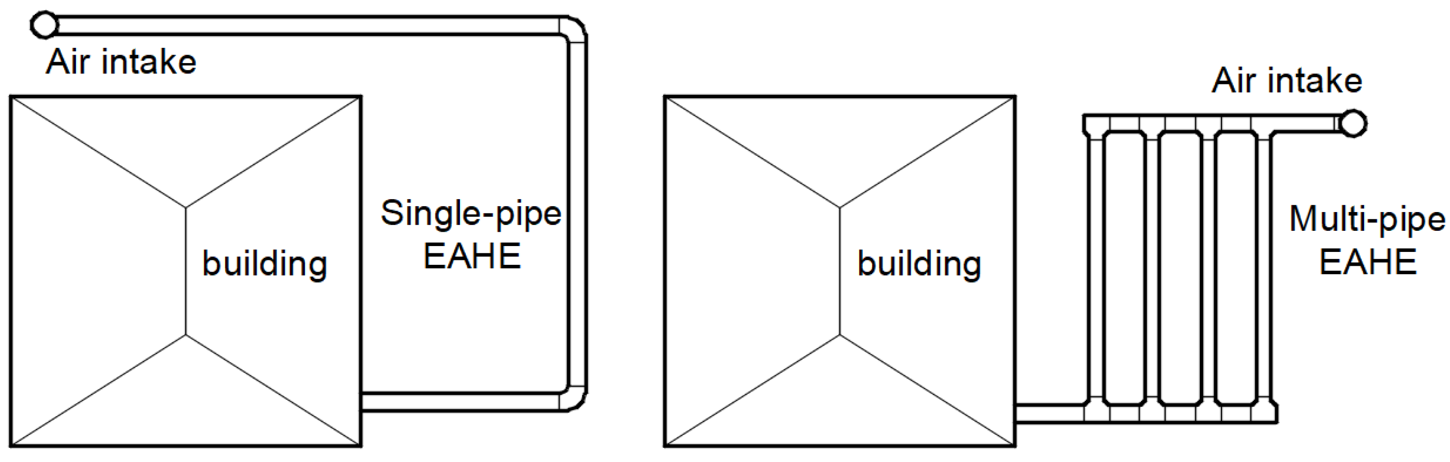
- the paper presents the results of experimental studies on pressure losses in multipipe heat exchangers made of 3, 5 and 7 parallel branches;
- these results were then used to compare pressure losses in these exchangers and analogous single-pipe exchangers (with the same total length of pipes used in their construction) for different airflows;
- then, analyses of the annual heat and cool gains and the annual electricity consumption by the EAHE supporting fan were conducted;
- finally, an analysis was carried out involving the search for the equivalent length of a single-pipe heat exchanger that would replace a given multipipe heat exchanger in terms of heat gains (the same heating capacity instead of the same length of the pipes)—analyses were performed for two boundary branch lengths and two selected airflows.
2. Materials and Methods
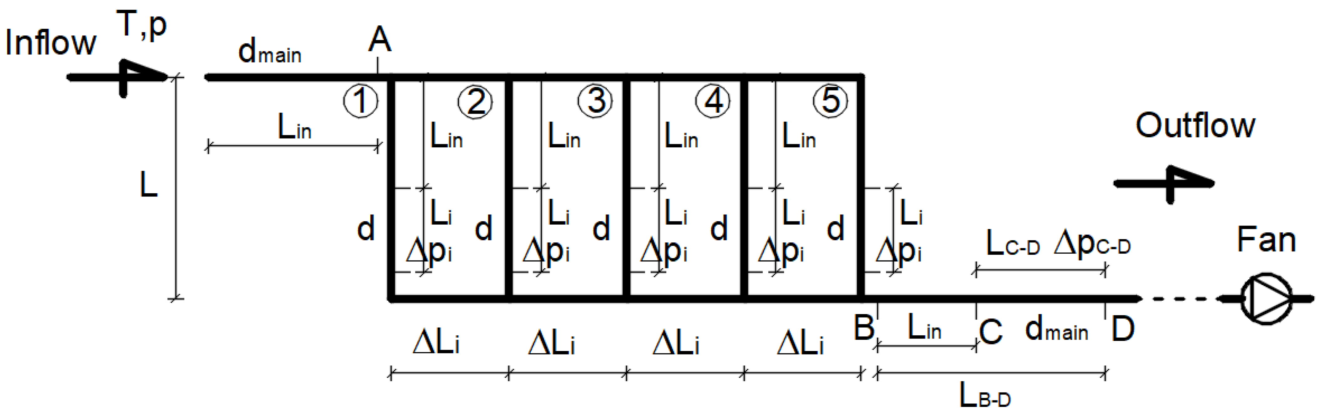
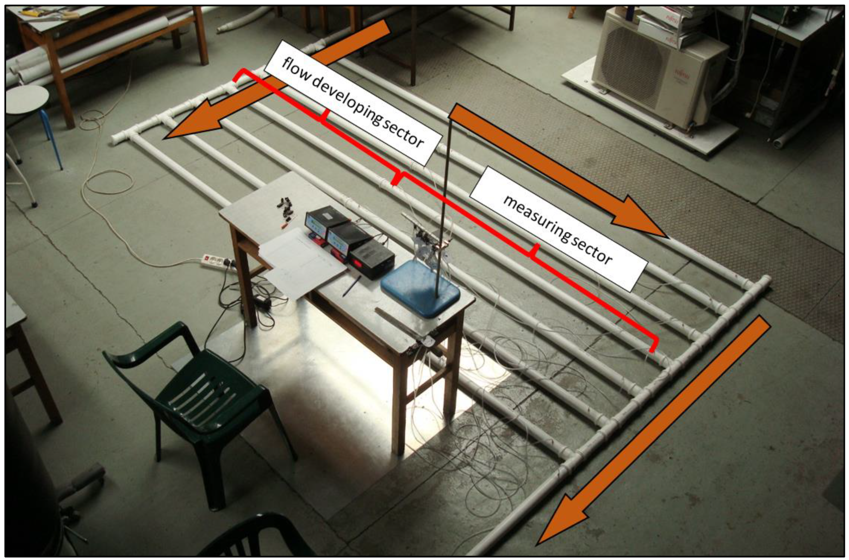
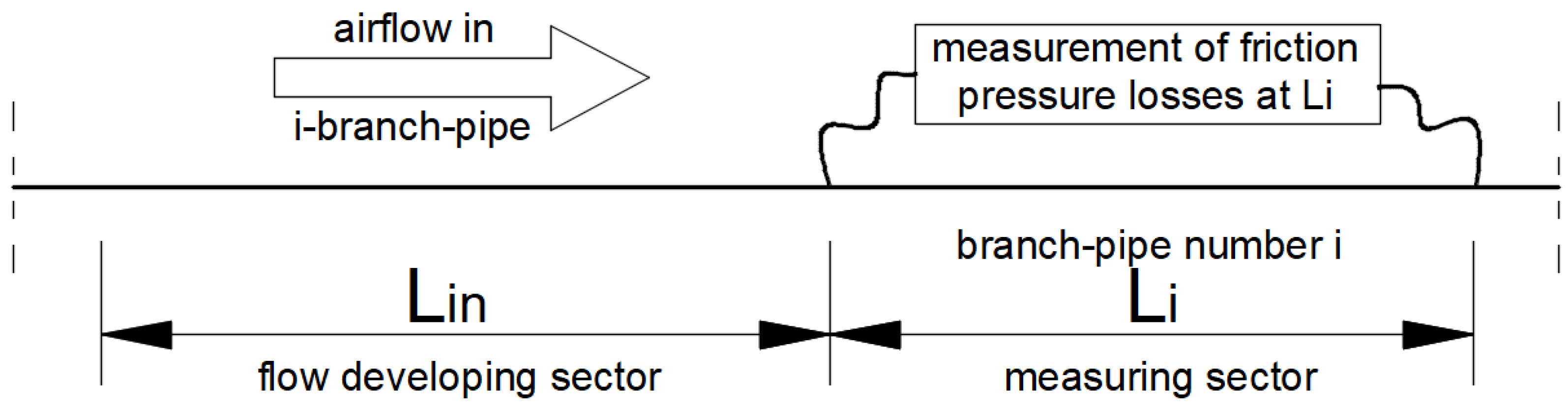
2.1. Experimental Setup for Pressure Loss Measurements
- w—velocity of the flowing air (m/s);
- d—internal diameter of the pipe (m);
- ν—kinematic viscosity of fluid (in this case: air) (m2/s).
- 3 branch-pipes, L = 76d, d = PP DN50, dmain = PP DN50;
- 5 branch-pipes, L = 76d, d = PP DN50, dmain = PP DN50;
- 7 branch-pipes, L = 76d, d = PP DN50, dmain = PP DN50.
2.2. Calculations of Annual Energy Gains
2.2.1. General Assumptions and Equations
- j−hour number of the year = 1 to 8760;
- time step, 1 h.
- n—number of branches in multipipe EAHE (3, 5 or 7), or 1 in the case of a single-pipe structure.
- —mass flowrate of air in the i branch of the multipipe exchanger, or total mass flowrate in the case of a single-pipe structure (kg/s);
- —specific heat of air in j hour of the year (J/(kgK));
- —temperature at the outlet of i branch of the exchanger (°C);
- —temperature at the inlet to the exchanger (external air temperature) in the j hour of the year (°C).
- —temperature of the ground at a given depth on day k of the year (°C);
- —external air temperature in j hour of the year (°C);
- —total heat transfer coefficient (W/(mK));
- D—external diameter of a pipe (m);
- d—internal diameter of the pipe (m);
- —thermal conductivity of the material constituting the pipe’s wall (W/(mK)).
- —thermal conductivity of air in j hour of the year, calculated as the average of the ground temperature at given depth and external air temperature (W/(mK)).
- —Reynolds number for i branch and at j hour of the year,
- —Prandtl number of air at j hour of the year.
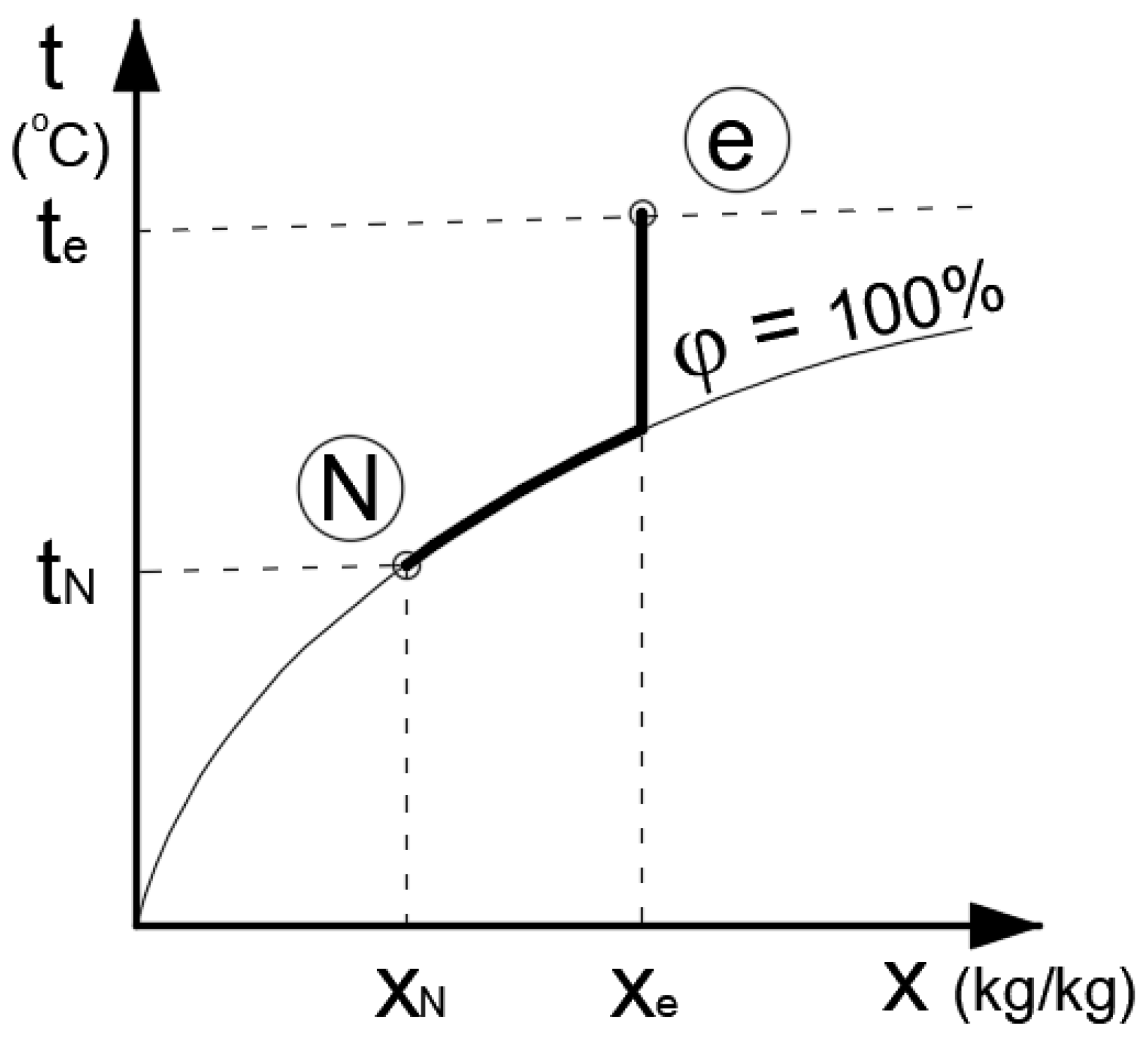
- —humidity content in the external air at j hour of the year, taken from climatic data (g/kg);
- —humidity content at the i branch outlet and in j hour of the year (g/kg);
- heat of condensation of water vapor (J/kg).
- —water vapor saturation pressure calculated at ti,j with Equation (14) from [54] (Pa);
- —actual pressure of air (Pa).
- a0 = 31.6885;
- a1 = 0.130986;
- a2 = 2.52493·10−5.
2.2.2. Soil Temperature at a Given Depth throughout the Year
- k—number of the day in the year, range: 1–365;
- H—depth of the exchanger placement, assumed as 2 m;
- ag—thermal diffusivity of the ground (m2/s);
- kv—vegetation coefficient, assumed 0.85;
- As—annual amplitude of the average monthly temperature of the dry thermometer, assumed for Poznan as 10.1 K;
- Tm—average annual temperature of the outside air, assumed for Poznan as 8.26 °C;
- ΔTm—difference between the temperature, Tm, and the average temperature of the ground at depth H = 10 m, assumed for Poznan as 2.24 K;
- To—phase shift, assumed for Poznan as 21 days.
- density: ρg = 1600 kg/m3;
- specific heat: cg = 753 J/(kgK);
- thermal conductivity: λg = 0.53 W/(mK).
2.2.3. Electric Energy and Primary Energy for Driving the Fan
- —total airflow through the EAHE in j hour during the year (m3/s);
- —pressure drop at EAHE in j hour during the year (Pa);
- —total efficiency of the fan (−).
3. Results
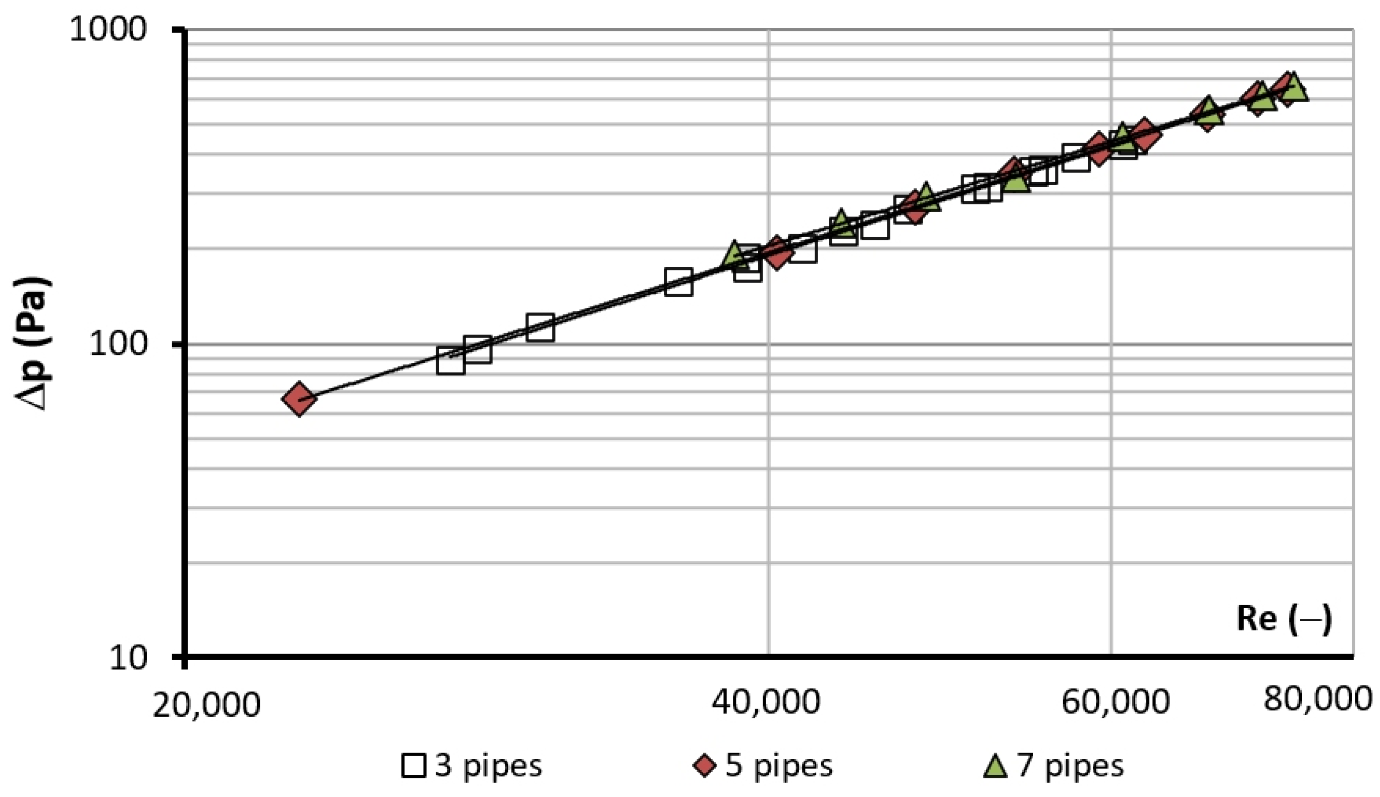
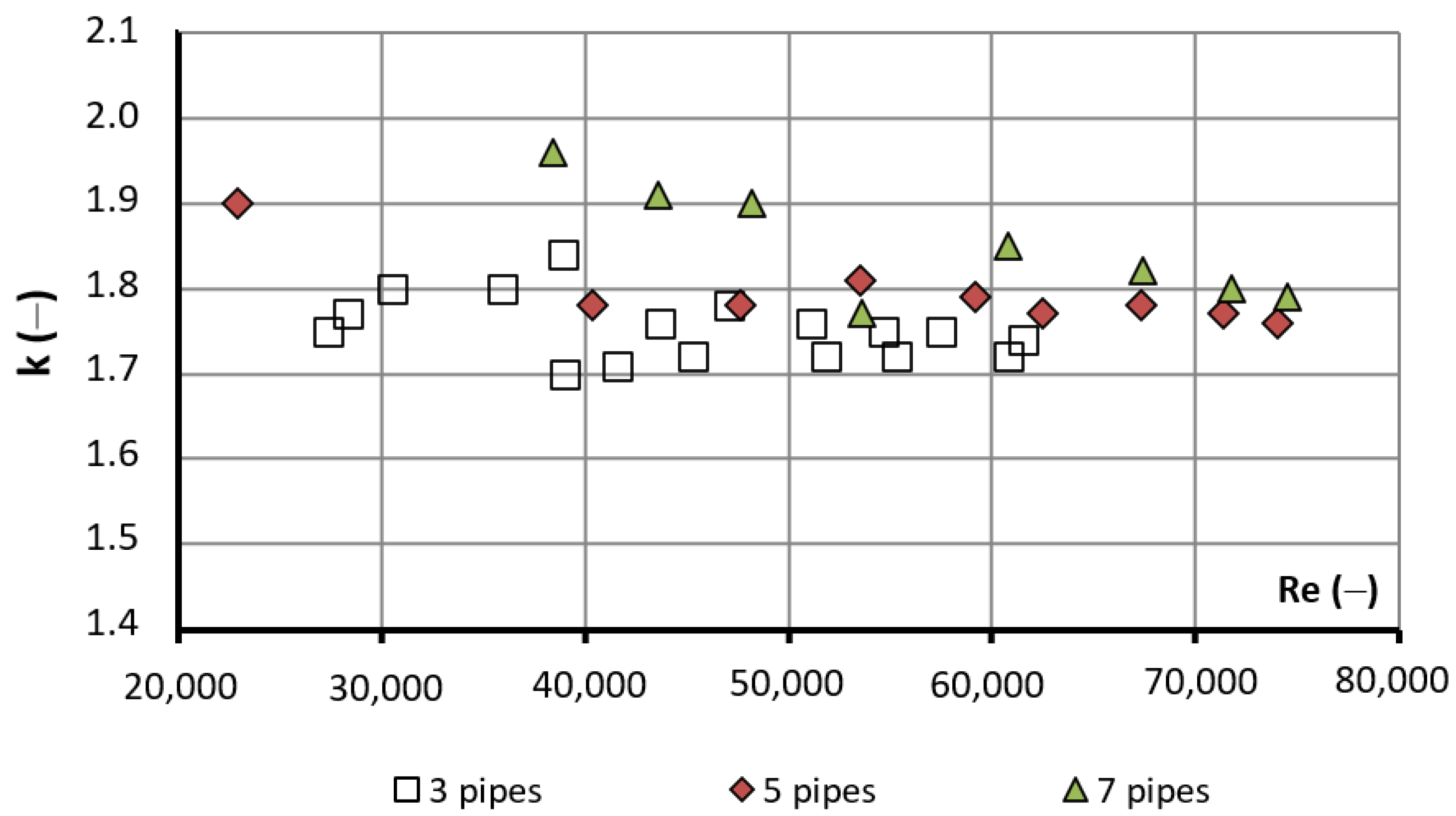
3.1. Experimental Flow Characteristics of Multipipe EAHEs
3.2. Total Pressure Losses in Single-Pipe and Multipipe EAHEs
- pipe diameters in single and multipipe EAHE were assumed to be the same and equal to PP DN200 (internal diameter d = 0.1844 m);
- the length of a one-pipe heat exchanger used for calculations resulted from the assumption of the same heat exchange surface between the compared exchangers; i.e., if, for example, a single-pipe exchanger was compared with a five-pipe exchanger with a length for each branch L = 150d, the length of the one-pipe heat exchanger used for calculations was 5 × 150d;
- in a single-pipe heat exchanger, additional pressure losses were assumed when changing the direction of the pipe every 50 m in order to take into account the limited ground surface for the heat exchanger’s construction.
- λ—friction factor calculated from the Blasius formula = 0.3164/Re0.25, (−);
- n—number of branches of equivalent multipipe EAHE (3, 5 or 7);
- L—length of single branch-pipe of the equivalent multipipe EAHE (m);
- d—internal diameter of pipe (m);
- —local pressure loss coefficient, assumed as 1 for a single elbow, taken from the handbook for engineering application [57], (−);
- —air density (kg/m3);
- w—air velocity in pipe (m/s).
- km—average coefficient of total pressure losses for exchangers constructed of 3, 5 and 7 pipes (−);
- w—air velocity in the manifold (in the main pipe, before division of air streams between branches of the exchanger) (m/s).
- w—air velocity in the manifold (in the main pipe, before separation of air streams between branches of the exchanger) (m/s);
- wm—average air velocity in a single branch-pipe, assuming the ideal distribution of air among all pipes: , where n is a number of parallel branch-pipes (m/s);
- λ—friction factor in a single branch-pipe calculated for wm; for laminar airflow, λ = 64/Re; for turbulent air flow, λ was calculated as 0.3164/Re0.25.
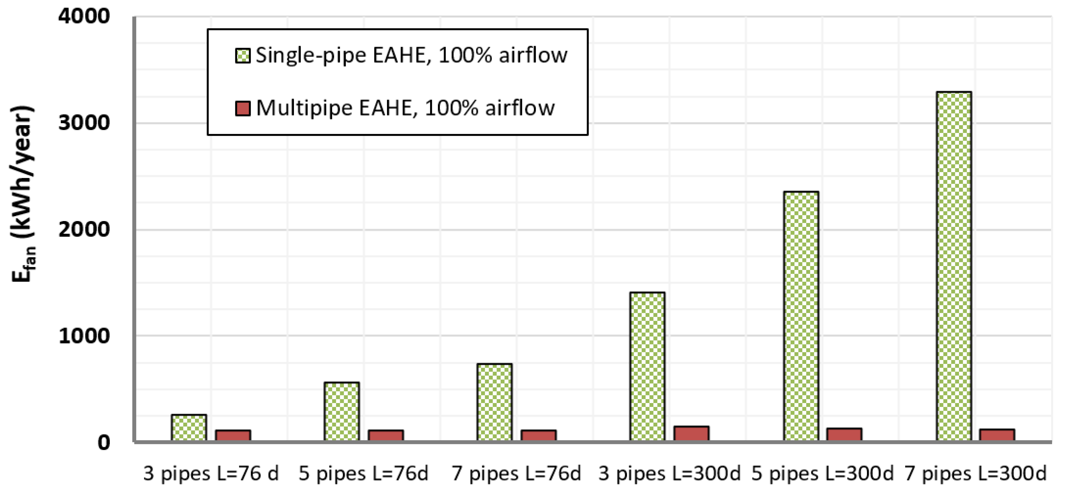
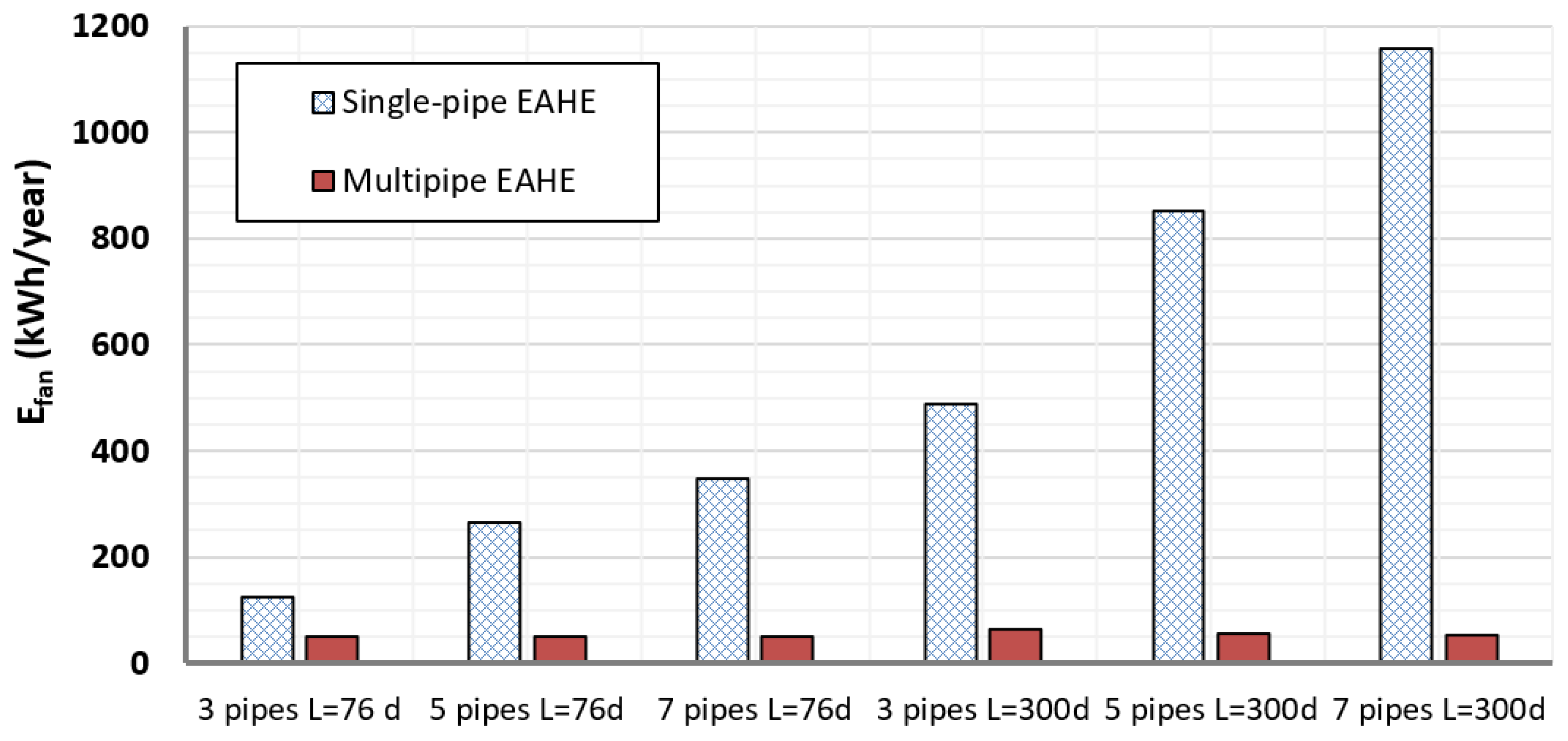
3.3. Energy Consuption for Fan Operation during a Year
- time of operation: one year;
- nominal (maximum) airflow: 600 m3/h;
- air flowrate changes during the single day in two variants: 100% of the time at maximum airflow or scheduled system usage. Schedule is presented in Table 4 (the schedule is representative of a building wherein users are fully staffed from 8 a.m. to 4 p.m. and performance is reduced outside of these hours);
- days of operation during the year: 250 (assuming periods in which the EAHE is not used);
- energy consumption for fan operation calculated for a single day and added day by day, taking into consideration the number of days on which the EAHE is used;
- total efficiency of the fan: 39%.
3.4. Full-Year Heating and Cooling Gains and Energy Cost of Harvesting Geothermal Energy
4. Discussion
5. Conclusions
- multipipe EAHEs could be replaced by single-pipe structures of with greater diameter with similar energy performance and electricity consumption during the year;
- for airflow of 600 m3/h, a seven-pipe EAHE of L = 14 m DN200 (a total of 7 × 14 = 98 m of DN200 pipe) could be replaced with a single-pipe DN250 of L = 35.5 m (35.5 m of DN250 pipe), with the annual electricity consumption lower by approximately 35%;
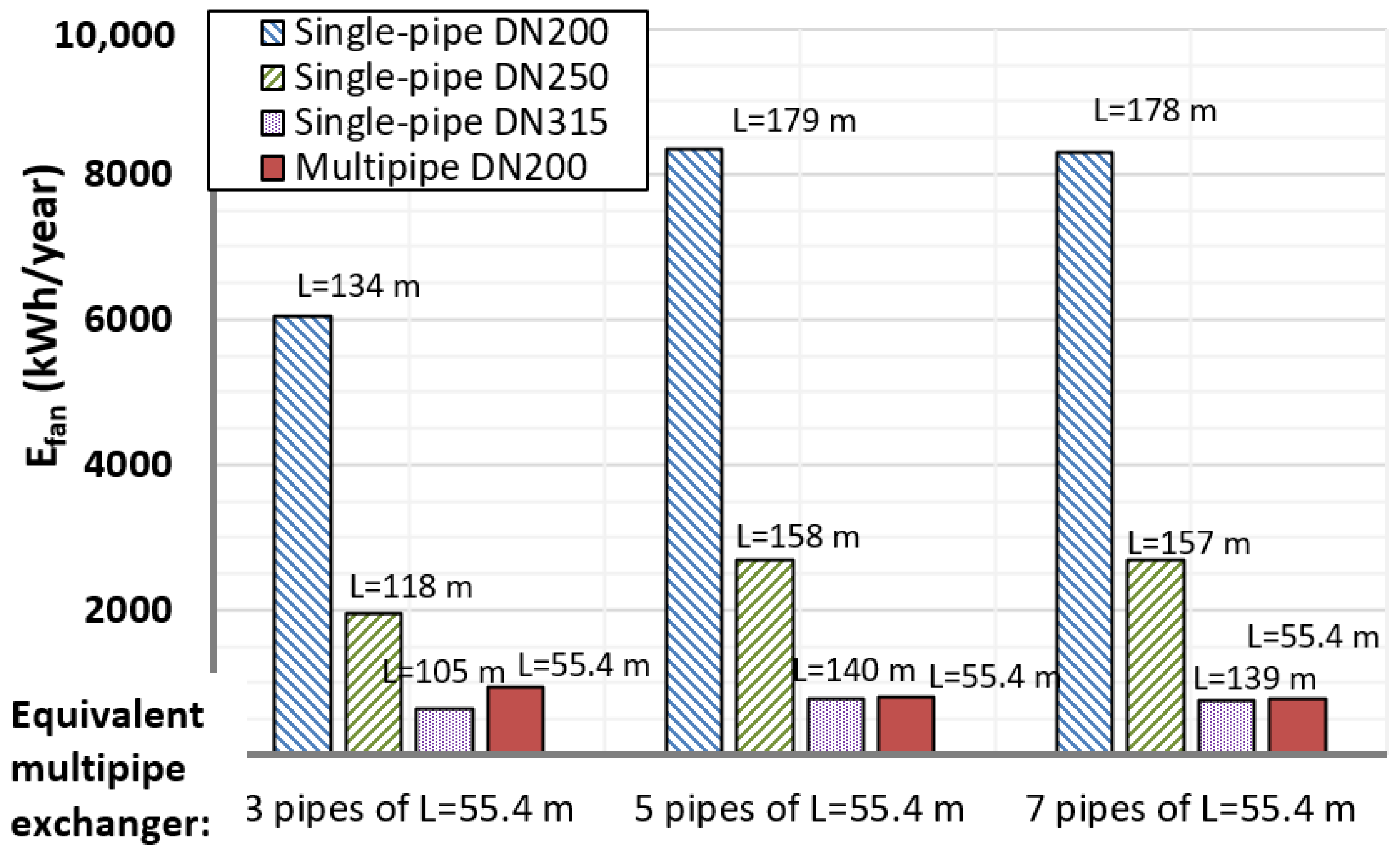
- for airflow of 1500 m3/h, a seven-pipe EAHE of L = 54.4 m DN200 (total 7 × 55.4 = 388 m of DN200 pipe) could be replaced with a single-pipe DN315 of L = 139 m (139 m of DN315 pipe), with almost the same annual electricity consumption;
- taking into account other designs of multipipe EAHEs (larger diameters of branches and/or manifolds) would change the heat yield and electricity consumption in favor of multipipe structures compared to single-pipe structures. However, such heat exchangers were not tested in this study and therefore were not analyzed in the calculations, which is an inspiration for future work born on the basis of the results of this article.
Author Contributions
Funding
Conflicts of Interest
Appendix A. Details of the Experimental Investigations


Appendix B. Uncertainty Analysis of the Experimental Results

| Measured Quantity (Independent Variable) | Value and Unit | Nominal Precision (Accuracy) |
|---|---|---|
| Li | 1850 mm | ±1 mm |
| LC−D | 1350 mm | ±1 mm |
| LB−D | 2850 mm | ±1 mm |
| di | 46.1 mm | ±0.1 mm |
| pmin − pmax | 99,800–102,000 Pa | ±100 Pa |
| ∆pi,min − ∆pi,max | 5–150 Pa | ±(0.05–0.5) Pa |
| ∆pC−D − ∆pC−D,max | 15–60 Pa | ±(0.05–0.5) Pa |
| ∆pA−D,min − ∆pA−D,max | 450–1900 | ±3 Pa |
| Tmin − Tmax | 294–298 K | ±0.5 K |
| Error | δLi | δLC−D | δLB−D | δdi | Δp | δ∆pi | δ∆pC−D | δ∆pA−D | δT | δ∆ptot | δVi | δVtot |
|---|---|---|---|---|---|---|---|---|---|---|---|---|
| Systematic | 0.03 | 0.04 | 0.02 | 0.13 | 0.06 | 0.30 | 0.30 | 0.30 | 0.10 | 0.32 | 0.91 | 0.91 |
| Random | 0.15 | 0.17 | 0.11 | 1.20 | 0.10 | 0.63 | 0.72 | 0.58 | 0.10 | 0.63 | 2.10 | 2.12 |
| General | 0.15 | 0.17 | 0.11 | 1.21 | 0.12 | 0.70 | 0.78 | 0.65 | 0.14 | 0.70 | 2.29 | 2.31 |
References
- Amanowicz, Ł.; Szczechowiak, E. Zasady projektowania systemów wentylacji budynków energooszczędnych. Ciepłownictwo Ogrzewnictwo Wentylacja 2017, 48, 72–78. [Google Scholar] [CrossRef]
- Ratajczak, K.; Michalak, K.; Narojczyk, M.; Amanowicz, Ł. Real Domestic Hot Water Consumption in Residential Buildings and Its Impact on Buildings’ Energy Performance—Case Study in Poland. Energies 2021, 14, 5010. [Google Scholar] [CrossRef]
- Dudkiewicz, E.; Fidorów-Kaprawy, N. Hybrid Domestic Hot Water System Performance in Industrial Hall. Resources 2020, 9, 65. [Google Scholar] [CrossRef]
- Dudkiewicz, E.; Fidorów-Kaprawy, N. The energy analysis of a hybrid hot tap water preparation system based on renewable and waste sources. Energy 2017, 127, 198–208. [Google Scholar] [CrossRef]
- Zender-Świercz, E. A Review of Heat Recovery in Ventilation. Energies 2021, 14, 1759. [Google Scholar] [CrossRef]
- Ratajczak, K.; Amanowicz, Ł.; Szczechowiak, E. Assessment of the air streams mixing in wall-type heat recovery units for ventilation of existing and refurbishing buildings toward low energy buildings. Energy Build. 2020, 227, 110427. [Google Scholar] [CrossRef]
- Zender-Świercz, E. Assessment of Indoor Air Parameters in Building Equipped with Decentralised Façade Ventilation Device. Energies 2021, 14, 1176. [Google Scholar] [CrossRef]
- Zender-Świercz, E. Improvement of indoor air quality by way of using decentralised ventilation. J. Build. Eng. 2020, 32, 101663. [Google Scholar] [CrossRef]
- Ratajczak, K.; Szczechowiak, E. Energy consumption decreasing strategy for indoor swimming pools—Decentralized Ventilation system with a heat pump. Energy Build. 2020, 206, 109574. [Google Scholar] [CrossRef]
- Ratajczak, K.; Basińska, M. The Well-Being of Children in Nurseries Does Not Have to Be Expensive: The Real Costs of Maintaining Low Carbon Dioxide Concentrations in Nurseries. Energies 2021, 14, 2035. [Google Scholar] [CrossRef]
- Romanska-Zapala, A.; Bomberg, M.; Dechnik, M.; Fedorczak-Cisak, M.; Furtak, M. On Preheating of the Outdoor Ventilation Air. Energies 2020, 13, 15. [Google Scholar] [CrossRef] [Green Version]
- Chmielewski, K.; Amanowicz, Ł. Bezprzeponowe powietrzne gruntowe wymienniki ciepła w układach wentylacji mechanicznej. Rynek instalacyjny 2017, 5, 76–80. [Google Scholar]
- Żukowski, M.; Topolańska, J. Comparison of thermal performance between tube and plate ground-air heat exchangers. Renew. Energy 2018, 115, 697–710. [Google Scholar] [CrossRef]
- Wei, H.; Yang, D. Performance evaluation of flat rectangular earth-to-air heat exchangers in harmonically fluctuating thermal environments. Appl. Therm. Eng. 2019, 162, 114–262. [Google Scholar] [CrossRef]
- Agrawal, K.K.; Misra, R.; Agrawal, G.D. CFD simulation study to evaluate the economic feasibility of backfilling materials for ground-air heat exchanger system. Geothermics 2021, 90, 102002. [Google Scholar] [CrossRef]
- Agrawal, K.K.; Misra, R.; Agrawal, G.D. Improving the thermal performance of ground air heat exchanger system using sand-bentonite (in dry and wet condition) as backfilling material. Renew. Energy 2020, 146, 2008–2023. [Google Scholar] [CrossRef]
- Sinacka, J.; Szczechowiak, E. Analiza eksploatacyjna budynku pasywnego w aspekcie komfortu klimatycznego i zużycia energii. Ciepłownictwo Ogrzewnictwo Wentylacja 2017, 48, 497–504. [Google Scholar] [CrossRef]
- Soares, N.; Rosa, N.; Monteiro, H.; Costa, J.J. Advances in standalone and hybrid earth-air heat exchanger (EAHE) systems for buildings: A review. Energy Build. 2021, 253, 111532. [Google Scholar] [CrossRef]
- Wei, H.; Yang, D.; Du, J.; Guo, X. Field experiments on the effects of an earth-to-air heat exchanger on the indoor thermal environment in summer and winter for a typical hot-summer and cold-winter region. Renew. Energy 2021, 167, 530–541. [Google Scholar] [CrossRef]
- Yang, D.; Wei, H.; Wang, J.; He, M. Coupled heat and moisture transfer model to evaluate earth-to-air heat exchangers exposed to harmonically fluctuating thermal environments. Int. J. Heat Mass Transf. 2021, 174, 121293. [Google Scholar] [CrossRef]
- Liu, Q.; Du, Z.; Fan, Y. Heat and Mass Transfer Behavior Prediction and Thermal Performance Analysis of Earth-to-Air Heat Exchanger by Finite Volume Method. Energies 2018, 11, 1542. [Google Scholar] [CrossRef] [Green Version]
- Sakhri, N.; Menni, Y.; Ameur, H. Experimental investigation of the performance of earth-to-air heat exchangers in arid environments. J. Arid Environ. 2020, 180, 104215. [Google Scholar] [CrossRef]
- Li, Y.; Long, T.; Bai, X.; Wang, L.; Li, W.; Liu, S.; Lu, J.; Cheng, Y.; Ye, K.; Huang, S. An experimental investigation on the passive ventilation and cooling performance of an integrated solar chimney and earth-air heat exchanger. Renew. Energy 2021, 175, 486–500. [Google Scholar] [CrossRef]
- Mirzazade Akbarpoor, A.; Haghighi Poshtiri, A.; Biglari, F. Performance analysis of domed roof integrated with earth-to-air heat exchanger system to meet thermal comfort conditions in buildings. Renew. Energy 2021, 168, 1265–1293. [Google Scholar] [CrossRef]
- Lapertot, A.; Cuny, M.; Kadoch, B.; le Métayer, O. Optimization of an earth-air heat exchanger combined with a heat recovery ventilation for residential building needs. Energy Build. 2021, 235, 110702. [Google Scholar] [CrossRef]
- Sakhri, N.; Menni, Y.; Ameur, H. Effect of the pipe material and burying depth on the thermal efficiency of earth-to-air heat exchangers. Case Stud. Chem. Environ. Eng. 2020, 2, 100013. [Google Scholar] [CrossRef]
- Domingues, A.M.B.; Nóbrega, E.S.B.; Ramalho, J.V.A.; Brum, R.S.; Quadros, R.S. Parameter analysis of Earth-air heat exchangers over multi-layered soils in South Brazil. Geothermics 2021, 93, 102074. [Google Scholar] [CrossRef]
- Hegazi, A.A.; Abdelrehim, O.; Khater, A. Parametric optimization of earth-air heat exchangers (EAHEs) for central air conditioning. Int. J. Refrig. 2021, 129, 278–289. [Google Scholar] [CrossRef]
- Minaei, A.; Talee, Z.; Safikhani, H.; Ghaebi, H. Thermal resistance capacity model for transient simulation of Earth-Air Heat Exchangers. Renew. Energy 2021, 167, 558–567. [Google Scholar] [CrossRef]
- Minaei, A.; Safikhani, H. A new transient analytical model for heat transfer of earth-to-air heat exchangers. J. Build. Eng. 2021, 33, 101560. [Google Scholar] [CrossRef]
- Mehdid, C.E.; Benchabane, A.; Rouag, A.; Moummi, N.; Melhegueg, M.A.; Moummi, A.; Benabdi, M.L.; Brima, A. Thermal design of Earth-to-air heat exchanger. Part II a new transient semi-analytical model and experimental validation for estimating air temperature. J. Clean. Prod. 2018, 198, 1536–1544. [Google Scholar] [CrossRef]
- Misra, R.; Bansal, V.; Agrawal, G.D.; Mathur, J.; Aseri, T. Transient analysis based determination of derating factor for earth air tunnel heat exchanger in summer. Energy Build. 2013, 58, 103–110. [Google Scholar] [CrossRef]
- Bansal, V.; Misra, R.; Agarwal, G.D.; Mathur, J. ‘Derating Factor’ new concept for evaluating thermal performance of earth air tunnel heat exchanger: A transient CFD analysis. Appl. Energy 2013, 102, 418–426. [Google Scholar] [CrossRef]
- Hamdane, S.; Mahboub, C.; Moummi, A. Numerical approach to predict the outlet temperature of earth-to-air-heat-exchanger. Therm. Sci. Eng. Prog. 2021, 21, 100806. [Google Scholar] [CrossRef]
- Liu, Z.; Sun, P.; Xie, M.; Zhou, Y.; He, Y.; Zhang, G.; Chen, D.; Li, S.; Yan, Z.; Qin, D. Multivariant optimization and sensitivity analysis of an experimental vertical earth-to-air heat exchanger system integrating phase change material with Taguchi method. Renew. Energy 2021, 173, 401–414. [Google Scholar] [CrossRef]
- Qin, D.; Liu, J.; Zhang, G. A novel solar-geothermal system integrated with earth-to-air heat exchanger and solar air heater with phase change material—Numerical modelling, experimental calibration and parametrical analysis. J. Build. Eng. 2021, 35, 101971. [Google Scholar] [CrossRef]
- Liu, Z.; Yu, Z.J.; Yang, T.; El Mankibi, M.; Roccamena, L.; Sun, Y.; Sun, P.; Li, S.; Zhang, G. Experimental and numerical study of a vertical earth-to-air heat exchanger system integrated with annular phase change material. Energy Convers. Manag. 2019, 186, 433–449. [Google Scholar] [CrossRef]
- Zhou, T.; Xiao, Y.; Huang, H.; Lin, J. Numerical study on the cooling performance of a novel passive system: Cylindrical phase change material-assisted earth-air heat exchanger. J. Clean. Prod. 2020, 245, 118907. [Google Scholar] [CrossRef]
- Baglivo, C.; D’Agostino, D.; Congedo, P.M. Design of a Ventilation System Coupled with a Horizontal Air-Ground Heat Exchanger (HAGHE) for a Residential Building in a Warm Climate. Energies 2018, 11, 2122. [Google Scholar] [CrossRef] [Green Version]
- Greco, A.; Masselli, C. The Optimization of the Thermal Performances of an Earth to Air Heat Exchanger for an Air Conditioning System: A Numerical Study. Energies 2020, 13, 6414. [Google Scholar] [CrossRef]
- Qi, D.; Zhao, C.; Li, S.; Chen, R.; Li, A. Numerical Assessment of Earth to Air Heat Exchanger with Variable Humidity Conditions in Greenhouses. Energies 2021, 14, 1368. [Google Scholar] [CrossRef]
- Boban, L.; Miše, D.; Herceg, S.; Soldo, V. Application and Design Aspects of Ground Heat Exchangers. Energies 2021, 14, 2134. [Google Scholar] [CrossRef]
- Amanowicz, Ł.; Wojtkowiak, J. Approximated flow characteristics of multi-pipe earth-to-air heat exchangers for thermal analysis under variable airflow conditions. Renew. Energy 2020, 158C, 585–597. [Google Scholar] [CrossRef]
- Amanowicz, Ł.; Wojtkowiak, J. Thermal performance of multi-pipe earth-to-air heat exchangers considering the non-uniform distribution of air between parallel pipes. Geothermics 2020, 88, 101896. [Google Scholar] [CrossRef]
- Amanowicz, Ł. Influence of geometrical parameters on the flow characteristics of multi-pipe earth-to-air heat exchangers—Experimental and CFD investigations. Appl. Energy 2018, 226, 849–861. [Google Scholar] [CrossRef]
- Amanowicz, Ł.; Wojtkowiak, J. Experimental flow characteristics of multi-pipe earth-to-air heat exchangers. Found. Civil Environ. Eng. 2012, 15, 5–18. [Google Scholar]
- Amanowicz, Ł. Doświadczalne Charakterystyki Przepływowe Powietrznych Wielorurowych Gruntowych Wymienników Ciepła; Wydawnictwo Politechniki Poznańskiej: Poznań, Poland, 2016; ISBN 978-83-7775-411-5. [Google Scholar]
- Amanowicz, Ł.; Wojtkowiak, J. Validation of CFD model for simulation of multi-pipe earth-to-air heat exchangers (EAHEs) flow performance. Therm. Sci. Eng. Prog. 2018, 5, 44–49. [Google Scholar] [CrossRef]
- Amanowicz, Ł.; Wojtkowiak, J. Experimental investigation and CFD simulation of multi-pipe earth-to-air heat exchangers (EAHEs) flow performance. E3S Web Conf. 2017, 22, 2. [Google Scholar] [CrossRef]
- Amanowicz, Ł.; Wojtkowiak, J. Wpływ oporu przewodzenia ciepła w gruncie oraz wykraplania wilgoci na obliczeniową ilość energii z gruntowego powietrznego wymiennika ciepła. Ciepłownictwo Ogrzewnictwo Wentylacja 2012, 43, 22–25. [Google Scholar]
- Amanowicz, Ł.; Wojtkowiak, J. Wpływ właściwości cieplnych gruntu na wydajność powietrznych rurowych gruntowych wymienników ciepła (PRGWC). Instal 2015, 10, 59–62. [Google Scholar]
- Bose, J.E.; Parker, J.D.; McQuiston, F.C. Design/data Manual for Closed—Loop Ground-Coupled Heat Pump Systems; ASHRAE: Atlanta, GA, USA, 1985. [Google Scholar]
- Kakac, S.; Shah, R.K.; Aung, W. Handbook of Single-Phase Convective Heat Transfer; John Willey and Sons: Hoboken, NJ, USA, 1987. [Google Scholar]
- Jahn, A. Methoden der Energetischen Prozessbewertung Raumtechnischer Anlagen und Grundlagen der Simulation, Diss; Technische Universität Berlin: Berlin, Germany, 1978. [Google Scholar]
- Popiel, C.O.; Wojtkowiak, J.; Biernacka, B. Measurements of temperature distribution in ground. Exp. Therm. Fluid Sci. 2001, 25, 301–309. [Google Scholar] [CrossRef]
- Popiel, C.O.; Wojtkowiak, J. Temperature distributions of ground in the urban region of Poznan City. Exp. Therm. Fluid Sci. 2013, 51, 135–148. [Google Scholar] [CrossRef]
- Marriott, M.J.; Featherstone, R.E.; Nalluri, C. Civil Engineering Hydruaulics, 5th ed.; Wiley-Blackwell: Hoboken, NJ, USA, 2009; p. 93. ISBN 978-1-4051-6195-4. [Google Scholar]
- Sinacka, J.; Szczechowiak, E.; Żabicka, P. Wpływ profilu użytkowania pomieszczenia na zapotrzebowanie na energię do ogrzewania i chłodzenia w budynku ze stropami grzewczo-chłodzącymi. Instal 2019, 10, 34–37. [Google Scholar] [CrossRef]
- Basińska, M.; Ratajczak, K.; Tomczyk, J. Energy performance for residential building—Comparison between theoretical method and real measurements. E3S Web Conf. 2018, 44, 9. [Google Scholar] [CrossRef]
- Ratajczak, K.; Szczechowiak, E. The Use of a Heat Pump in a Ventilation Unit as an Economical and Ecological Source of Heat for the Ventilation System of an Indoor Swimming Pool Facility. Energies 2020, 13, 6695. [Google Scholar] [CrossRef]
- Qi, D.; Li, A.; Li, S.; Zhao, C. Comparative analysis of earth to air heat exchanger configurations based on uniformity and thermal performance. Appl. Therm. Eng. 2021, 183, 116152. [Google Scholar] [CrossRef]


| Measured Value | Apparatus | Precision |
|---|---|---|
| T (°C) | Laboratory thermometer | ±0.5 °C |
| p (Pa) | Laboratory barometer | ±100 Pa |
| Δpi, ΔpC–D, ΔpA–D (Pa) | Micromanometer with range 0–50 Pa | ±0.05 Pa |
| Micromanometer with range 50–500 Pa | ±0.5 Pa | |
| Micromanometer with range 500–1990 Pa | ±3.0 Pa | |
| L (m), Li (m), ΔL (m) | Measuring tape | ±1.0 mm |
| 3 Pipes | 5 Pipes | 7 Pipes |
|---|---|---|
| 1.77 | 1.83 | 1.87 |
| Average for 3, 5 and 7 pipes: km = 1.82 | ||
| Type of EAHE: | Single-Pipe (Pipes in Series) | Multipipe (Parallel Pipes) | |||||
|---|---|---|---|---|---|---|---|
| V = 200 m3/h, Re = 26,597 | |||||||
| Number of pipes: | 3 | 5 | 7 | 3 | 5 | 7 | |
| Length of a single pipe: | 76d | 15.0 | 30.4 | 40.4 | 4.8 | 4.8 | 4.8 |
| 150d | 35.0 | 60.1 | 85.2 | 5.6 | 5.1 | 5.0 | |
| 300d | 75.3 | 125.5 | 175.7 | 7.0 | 5.7 | 5.3 | |
| V = 600 m3/h, Re = 79,790 | |||||||
| Number of pipes: | 3 | 5 | 7 | 3 | 5 | 7 | |
| Length of a single pipe: | 76d | 102.8 | 219.3 | 287.8 | 43.6 | 43.6 | 43.6 |
| 150d | 250.8 | 434.0 | 617.2 | 48.5 | 45.6 | 44.7 | |
| 300d | 549.5 | 915.9 | 1282.3 | 58.4 | 49.6 | 46.9 | |
| Hour | Airflow | Hour | Airflow |
|---|---|---|---|
| 0 | 40% | 12 | 100% |
| 1 | 40% | 13 | 100% |
| 2 | 40% | 14 | 100% |
| 3 | 40% | 15 | 100% |
| 4 | 40% | 16 | 100% |
| 5 | 40% | 17 | 70% |
| 6 | 70% | 18 | 70% |
| 7 | 70% | 19 | 40% |
| 8 | 100% | 20 | 40% |
| 9 | 100% | 21 | 40% |
| 10 | 100% | 22 | 40% |
| 11 | 100% | 23 | 40% |
| Number of Pipes: | 3 | 5 | 7 | |
|---|---|---|---|---|
| Length of a single pipe: | 76d | 10% | 15% | 25% |
| 300d | 5% | 10% | 20% | |
| Type of EAHE: | Single-Pipe (Pipes in Series) | Multipipe (Parallel Pipes) | |||||
|---|---|---|---|---|---|---|---|
| Number of Pipes: | 3 | 5 | 7 | 3 | 5 | 7 | |
| EAHE length: | 3 × 76d | 5 × 76d | 7 × 76d | 3 × 76d | 5 × 76d | 7 × 76d | |
| Benefits | Heat (kWh/year) | 2179 | 3059 | 3668 | 1654 | 2027 | 2066 |
| Cool (kWh/year) | 569 | 851 | 1085 | 436 | 557 | 584 | |
| Cost | Electric energy (kWh/year) | 112 | 238 | 313 | 47 | 47 | 47 |
| PE for driving fan (kWh/year) | 336 | 714 | 939 | 141 | 141 | 141 | |
| EAHE length: | 3 × 300d | 5 × 300d | 7 × 300d | 3 × 300d | 5 × 300d | 7 × 300d | |
| Benefits | Heat (kWh/year) | 4511 | 5037 | 5207 | 3972 | 4221 | 3937 |
| Cool (kWh/year) | 1504 | 1858 | 1991 | 1272 | 1469 | 1430 | |
| Cost | Electric energy (kWh/year) | 597 | 994 | 1391 | 63 | 53 | 50 |
| PE for driving fan (kWh/year) | 1791 | 2982 | 4173 | 189 | 159 | 150 | |
| Type of EAHE: | Single-Pipe (Pipes in Series) | Multipipe (Parallel Pipes) | |||||
|---|---|---|---|---|---|---|---|
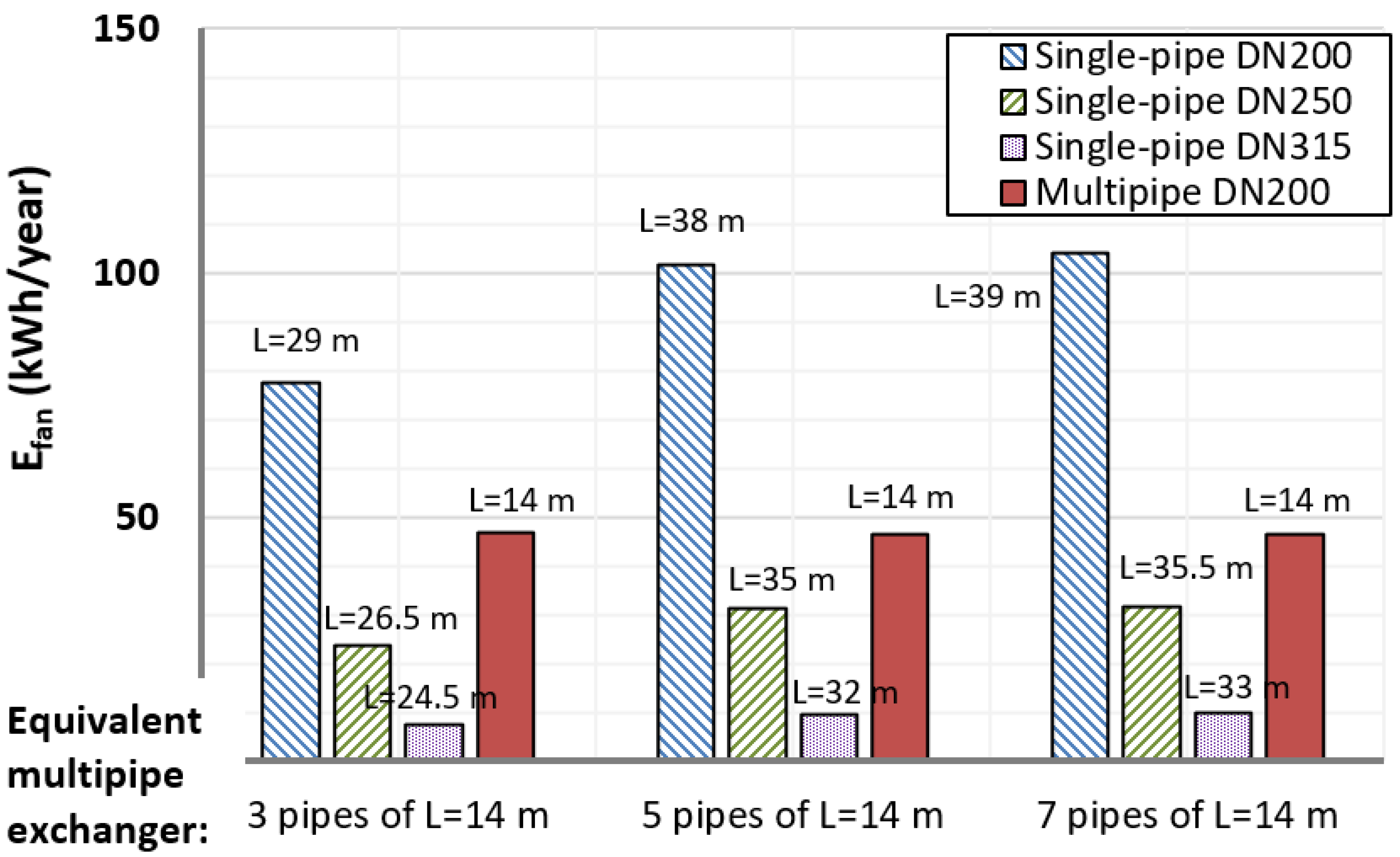
| EAHE length: | 1 × 29 m DN200 | 1 × 38 m DN200 | 1 × 39 m DN200 | 3 × 14 m DN200 | 5 × 14 m DN200 | 7 × 14 m DN200 | |
| Equivalent multipipe EAHE | 3 × 14 m DN200 | 5 × 14 m DN200 | 7 × 14 m DN200 | ||||
| Benefits | Heat (kWh/year) | 1643 | 2064 | 2064 | 1654 | 2027 | 2066 |
| Cool (kWh/year) | 416 | 535 | 535 | 436 | 557 | 584 | |
| Cost | Electric energy (kWh/year) | 78 | 104 | 104 | 47 | 47 | 47 |
| PE for driving fan (kWh/year) | 234 | 312 | 312 | 141 | 141 | 141 | |
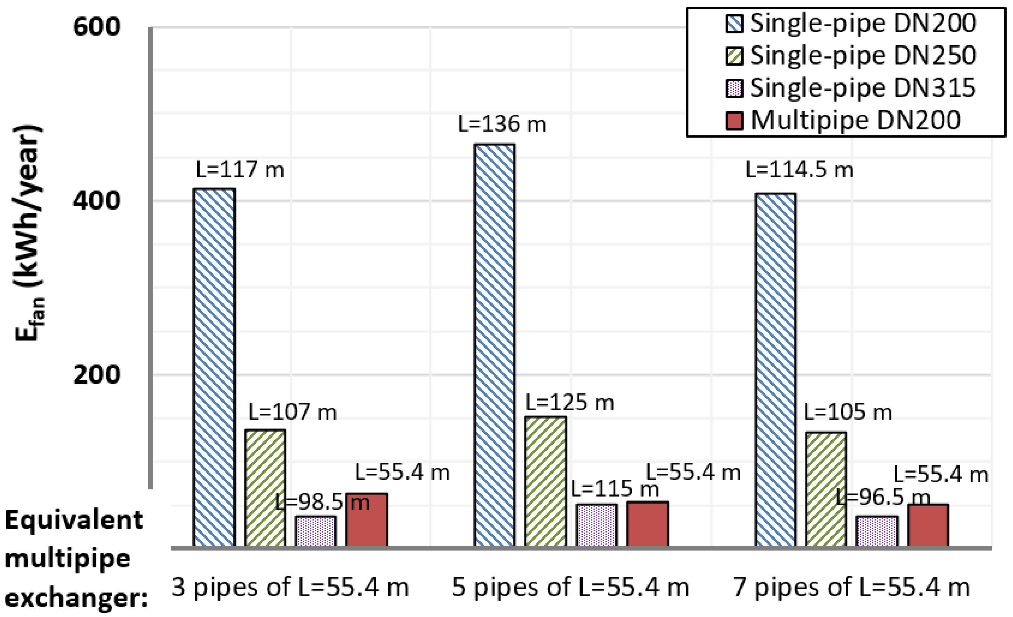
| EAHE length: | 1 × 117 m DN200 | 1 × 136 m DN200 | 1 × 114.5 m DN200 | 3 × 55.4 m DN200 | 5 × 55.4 m DN200 | 7 × 55.4 m DN200 | |
| Equivalent multipipe EAHE: | 3 × 55.4 m DN200 | 5 × 55.4 m DN200 | 7 × 55.4 m DN200 | ||||
| Benefits | Heat (kWh/year) | 3973 | 4218 | 3937 | 3972 | 4221 | 3937 |
| Cool (kWh/year) | 1221 | 1342 | 1204 | 1272 | 1469 | 1430 | |
| Cost | Electric energy (kWh/year) | 414 | 465 | 408 | 63 | 53 | 50 |
| PE for driving fan (kWh/year) | 1242 | 1395 | 1224 | 189 | 159 | 150 | |
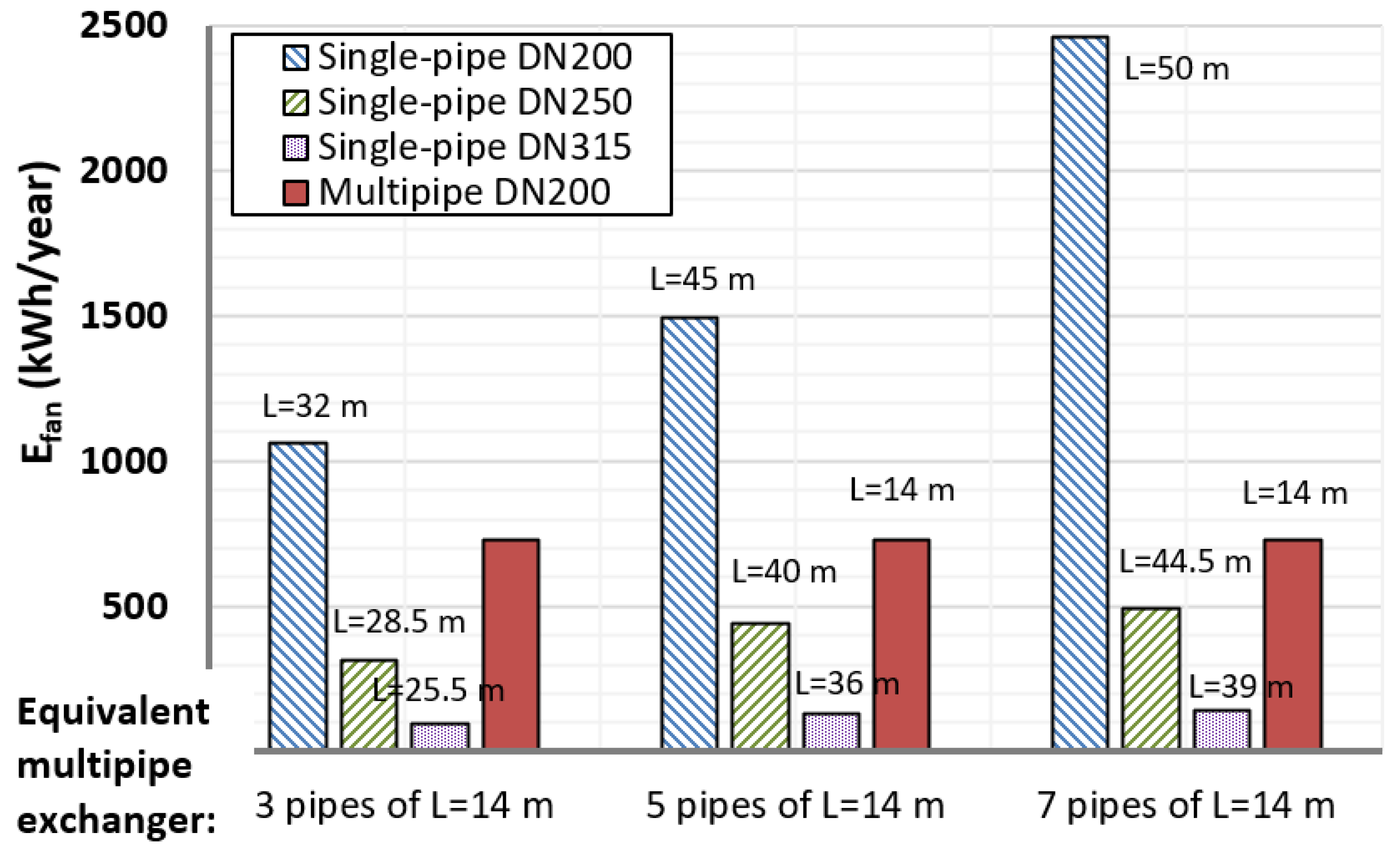
| Type of EAHE: | Single-Pipe (Pipes in Series) | Multipipe (Parallel Pipes) | |||||
|---|---|---|---|---|---|---|---|
| EAHE length: | 1 × 26.5 m DN250 | 1 × 35 m DN250 | 1 × 35.5 m DN250 | 3 × 14 m DN200 | 5 × 14 m DN200 | 7 × 14 m DN200 | |
| Equivalent multipipe EAHE: | 3 × 14 m DN200 | 5 × 14 m DN200 | 7 × 14 m DN200 | ||||
| Benefits | Heat (kWh/year) | 1641 | 2032 | 2054 | 1654 | 2027 | 2066 |
| Cool (kWh/year) | 420 | 531 | 538 | 436 | 557 | 584 | |
| Cost | Electric energy (kWh/year) | 24 | 31 | 32 | 47 | 47 | 47 |
| PE for driving fan (kWh/year) | 72 | 93 | 96 | 141 | 141 | 141 | |
| EAHE length: | 1 × 10⁷ m DN250 | 1 × 125 m DN250 | 1 × 10⁵ m DN250 | 3 × 54.4 m DN200 | 5 × 54.4 m DN200 | 7 × 54.4 m DN200 | |
| Equivalent multipipe EAHE: | 3 × 54.4 m DN200 | 5 × 54.4 m DN200 | 7 × 54.4 m DN200 | ||||
| Benefits | Heat (kWh/year) | 3975 | 4229 | 3942 | 3972 | 4221 | 3937 |
| Cool (kWh/year) | 1228 | 1353 | 1213 | 1272 | 1469 | 1430 | |
| Cost | Electric energy (kWh/year) | 136 | 152 | 134 | 63 | 53 | 50 |
| PE for driving fan (kWh/year) | 408 | 456 | 402 | 189 | 159 | 150 | |
| Type of EAHE: | Single-Pipe (Pipes in Series) | Multipipe (Parallel Pipes) | |||||
|---|---|---|---|---|---|---|---|
| EAHE Length: | 1 × 24.5 m DN315 | 1 × 32 m DN315 | 1 × 33 m DN315 | 3 × 14 m DN200 | 5 × 14 m DN200 | 7 × 14 m DN200 | |
| Equivalent multipipe EAHE: | 3 × 14 m DN200 | 5 × 14 m DN200 | 7 × 14 m DN200 | ||||
| Benefits | Heat (kWh/year) | 1645 | 2019 | 2065 | 1654 | 2027 | 2066 |
| Cool (kWh/year) | 426 | 534 | 547 | 436 | 557 | 584 | |
| Cost | Electric energy (kWh/year) | 7 | 10 | 10 | 47 | 47 | 47 |
| PE for driving fan (kWh/year) | 21 | 30 | 30 | 141 | 141 | 141 | |
| EAHE length: | 1 × 98.5 m DN315 | 1 × 115 m DN315 | 1 × 96.5 m DN315 | 3 × 54.4 m DN200 | 5 × 54.4 m DN200 | 7 × 54.4 m DN200 | |
| Equivalent multipipe EAHE: | 3 × 54.4 m DN200 | 5 × 54.4 m DN200 | 7 × 54.4 m DN200 | ||||
| Benefits | Heat (kWh/year) | 3973 | 4228 | 3938 | 3972 | 4221 | 3937 |
| Cool (kWh/year) | 1235 | 1360 | 1218 | 1272 | 1469 | 1430 | |
| Cost | Electric energy (kWh/year) | 37 | 50 | 37 | 63 | 53 | 50 |
| PE for driving fan (kWh/year) | 111 | 150 | 111 | 189 | 159 | 150 | |
Publisher’s Note: MDPI stays neutral with regard to jurisdictional claims in published maps and institutional affiliations. |
© 2021 by the authors. Licensee MDPI, Basel, Switzerland. This article is an open access article distributed under the terms and conditions of the Creative Commons Attribution (CC BY) license (https://creativecommons.org/licenses/by/4.0/).
Share and Cite
Amanowicz, Ł.; Wojtkowiak, J. Comparison of Single- and Multipipe Earth-to-Air Heat Exchangers in Terms of Energy Gains and Electricity Consumption: A Case Study for the Temperate Climate of Central Europe. Energies 2021, 14, 8217. https://0-doi-org.brum.beds.ac.uk/10.3390/en14248217
Amanowicz Ł, Wojtkowiak J. Comparison of Single- and Multipipe Earth-to-Air Heat Exchangers in Terms of Energy Gains and Electricity Consumption: A Case Study for the Temperate Climate of Central Europe. Energies. 2021; 14(24):8217. https://0-doi-org.brum.beds.ac.uk/10.3390/en14248217
Chicago/Turabian StyleAmanowicz, Łukasz, and Janusz Wojtkowiak. 2021. "Comparison of Single- and Multipipe Earth-to-Air Heat Exchangers in Terms of Energy Gains and Electricity Consumption: A Case Study for the Temperate Climate of Central Europe" Energies 14, no. 24: 8217. https://0-doi-org.brum.beds.ac.uk/10.3390/en14248217