
Experimental Study of the Direct Drive Hydraulic System with the Torque Mode


School of Mechatronics Engineering, Harbin Institute of Technology, West Dazhi Street No.92, Harbin 150001, China
*
Author to whom correspondence should be addressed.
Energies 2021, 14(4), 941; https://0-doi-org.brum.beds.ac.uk/10.3390/en14040941
Submission received: 14 January 2021
/
Revised: 5 February 2021
/
Accepted: 8 February 2021
/
Published: 10 February 2021
(This article belongs to the Special Issue Challenges and Research Trends of Computational Hydraulics and Fluid Mechanics)
Abstract
:The torque mode is more suitable for the direct drive 6 degree of freedom (6-DOF) parallel mechanism than the speed mode that both dynamic coupling and current coupling among motors are easily solved, but its key parameters and dynamic characteristics have never been studied, which are important and are the goals of this paper. First the hydraulic system of the direct drive 6-DOF parallel mechanism is simplified. Then the transfer function of the direct drive hydraulic system with the torque mode is deduced together with that of the speed mode. Finally, comparative experiments are conducted. Results show that the dynamic characteristics of the system with the torque mode which are generally worse than those with the speed mode, are mainly determined by the parameters of the motor-pump second-order element of the transfer function composed of two under-damped second-order elements, proportion differentiation (PD) control strategy and dynamic pressure feedback (DPF) control strategy are useful for the system with the torque mode, but practical and effective methods are still needed.
1. Introduction
Energy is important in any societies [1,2,3]. Direct drive hydraulic system has been widely used for the advantages of high energy efficiency, easy installation, high reliability and so on [4,5,6,7,8,9]. In general, the dynamic characteristics of the direct drive hydraulic system are not satisfied, since the speed helps the modeling and design of the control system and is usually adopted as the drive mode of the servo motor of the direct drive hydraulic systems, structure and control methods of the direct drive hydraulic system with the speed mode attract increasing interest. Schmidt et al., 2017 developed a Speed-variable Switched Differential Pump (SvSDP) drive for asymmetric cylinders [10]. Minav et al., 2017 proposed a fuzzy controller for a direct drive hydraulic system aiming at the speed of the servo motor, and excellent control capabilities of speed and position were accomplished [11]. Helian et al., 2019 designed an adaptive robust controller for a direct drive system, where a servomotor pump was adopted as the drive part [12]. A triple-loop feedback control strategy was developed by Tianyi et al., 2018 to extend the pressure bandwidth of the driving element in a humanoid robot [13,14]. It’s also very convenient to apply adaptive control strategy, intelligent hybrid control strategy, predictive control strategy and sliding mode control strategy to the direct drive hydraulic systems with the speed mode [15,16,17,18,19]. Li et al., 2018 analyzed the natural frequency characteristics of an electro-hydrostatic actuator (EHA), and the influence of the moment of inertia of the motorpump unit on its dynamic performance was also discussed [20]. Although the torque-loop locates inside the speed-loop with a faster response, and the torque mode is also provided in all servo motors with vector control, few papers of the direct drive hydraulic system with the torque mode can be found.
Both dynamic coupling and current coupling among motors exist in the direct drive 6-DOF parallel mechanism. Combined with modal space coordinate transformation, the speed mode can only solve the dynamic coupling, while the torque mode can solve both dynamic coupling and current coupling with modal space coordinate transformation. So, the torque mode is more suitable for the direct drive 6-DOF parallel mechanism [21]. However, the key parameters and the dynamic characteristics of the direct drive hydraulic system for the direct drive 6-DOF parallel mechanism with the torque mode have never been studied, which are important and are studied by the combination of the transfer function and the experiment of the direct drive hydraulic system with the torque mode, compared with those with the speed mode in this paper.
2. Introduction to the Direct Drive Hydraulic System
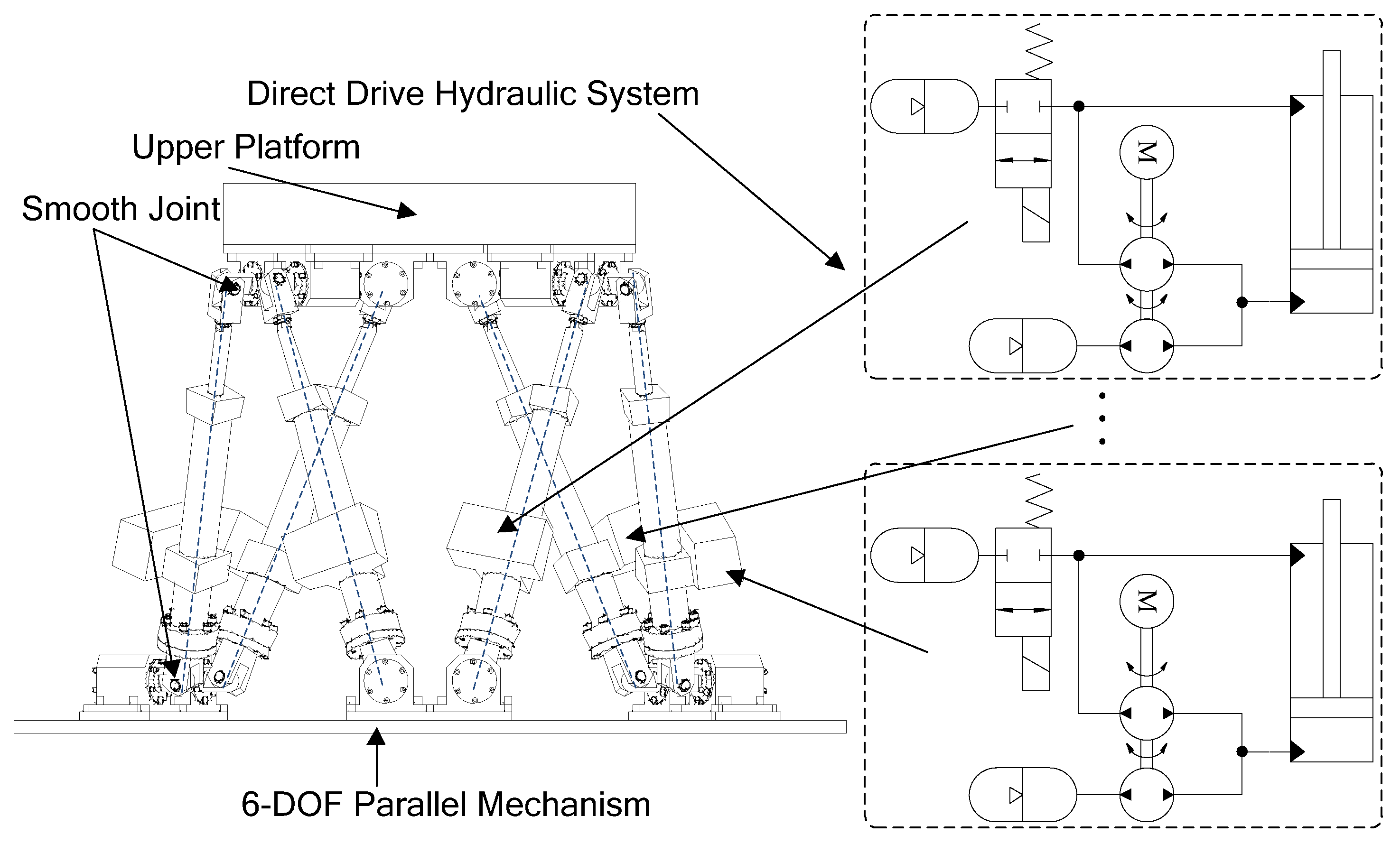
The structure and the direct drive hydraulic system of the direct drive 6-DOF parallel mechanism in [21] are shown in Figure 1.
The motion of the upper platform which is usually made of steel is generated by six symmetrical direct drive legs. Usually, smooth joints which can eliminate the effects of the joint friction on its dynamics characteristics are often adopted in the parallel mechanism, so the load of the parallel mechanism is mainly composed of the inertia load. Since the hydraulic system of each leg of the direct drive 6-DOF parallel mechanism is the same, and the complete coupled transfer function with the torque mode can be transformed into six independent single DOF control systems with modal space coordinate transformation, which are quite similar to that of a single DOF direct drive hydraulic system with inertia load [21], the hydraulic system of the direct drive 6-DOF parallel mechanism can be simplified to a single DOF hydraulic system which costs much less and the study of this paper can also be carried out with the simplified system, which should be exactly the same with the hydraulic system of each leg of the direct drive 6-DOF parallel mechanism. It is worth noting that the hydraulic and electric components of the single DOF hydraulic system should be selected according to the requirements of the direct drive 6-DOF parallel mechanism. The schematic diagram of the simplified single DOF direct drive hydraulic system is shown in Figure 2.
From Figure 2, it can be seen that an inertia load which is used to imitate the load of the parallel mechanism is mounted on end of the vertical asymmetric cylinder driven by a single motor with a double gear pump. Pressures of the two cavities of the cylinder and the accumulators are designed equal to compensate the gravity of the system, and since the displacement ratio of the double pump is set to be the same as the area ratio of the two cavities of the hydraulic cylinder, the speed gains of the two direction movements of the hydraulic system are the same and the gravity load can be ignored during the motion. When the hydraulic system is stationary in the middle position, the pressure relationship between the two cavities of the hydraulic cylinder is as follows:
where and are the pressures of the two cavities of the cylinder, , is the gravity load of the system, and are piston areas of the two cavities of the cylinder.
3. Transfer Function of the Direct Drive Hydraulic System
Ignoring the influence of the accumulator and coulomb friction on the transfer function, the torque balance equation of the motor-pump unit in Figure 2 is as follows:
where represents the motor torque coefficient, is the current of the q axis of the servo motor, is the moment of inertia of the motor-pump unit, while represents the viscous damping coefficient, is the sum displacement of the coaxial gear pump, , and represent the two displacements of the two pump units and is introduced to represent the load pressure of the system, , . The flow continuity equation of the direct drive hydraulic system is as follows:
where represents the volume efficiency of the two pump units, represents the speed of the motor-pump unit, , , represents the leakage coefficient, is the equivalent volume of the direct drive system, and represents the bulk modulus of the hydraulic oil. The dynamic equation of the direct-drive hydraulic system is as follows:
where represents the viscous damping coefficient of the cylinder, is the load mass of the system. Combining Equation (3) with Equation (4), the open-loop transfer function of the system in Figure 2 with the speed mode can be obtained with as:
similarly, the open-loop transfer function of the direct drive hydraulic system with the torque mode can be obtained as:
It is found that the open-loop transfer function of the direct drive hydraulic system with the speed mode is only composed of an integral element and a second-order element, while the open-loop transfer function of the direct drive hydraulic system with the torque mode is composed of an integral element, an inertia element and a second-order element. According to Equation (5) and Equation (6), the closed-loop transfer function of the system with the speed mode is composed of an inertial element and a second-order element with proportion control strategy, while the closed-loop transfer function of the system with the torque mode can be decomposed into two second-order elements with proportion control strategy. Combining Equation (2) with Equation (6), it can be known that the added second-order element of the transfer function with the torque mode is closely related to the parameters of the motor-pump unit. Therefore, the transfer function of the direct drive hydraulic system with the torque mode can be roughly divided into a motor-pump second-order element and a dynamic second-order element due to the mechanical parts. Since both Equation (3) and Equation (4) apply to the speed mode and the torque mode, the parameters of the second-order element with the speed mode and the dynamic second-order element with the torque mode are quite similar. According to [21], both proportion differentiation (PD) control strategy and dynamic pressure feedback (DPF) control strategy which are designed to increase the bandwidth of the direct drive 6-DOF parallel mechanism should also be adopted to improve the dynamic performances of the direct drive hydraulic system in Figure 2 with the torque mode, experimental verification is also carried out.
4. Introduction to the Experimental System
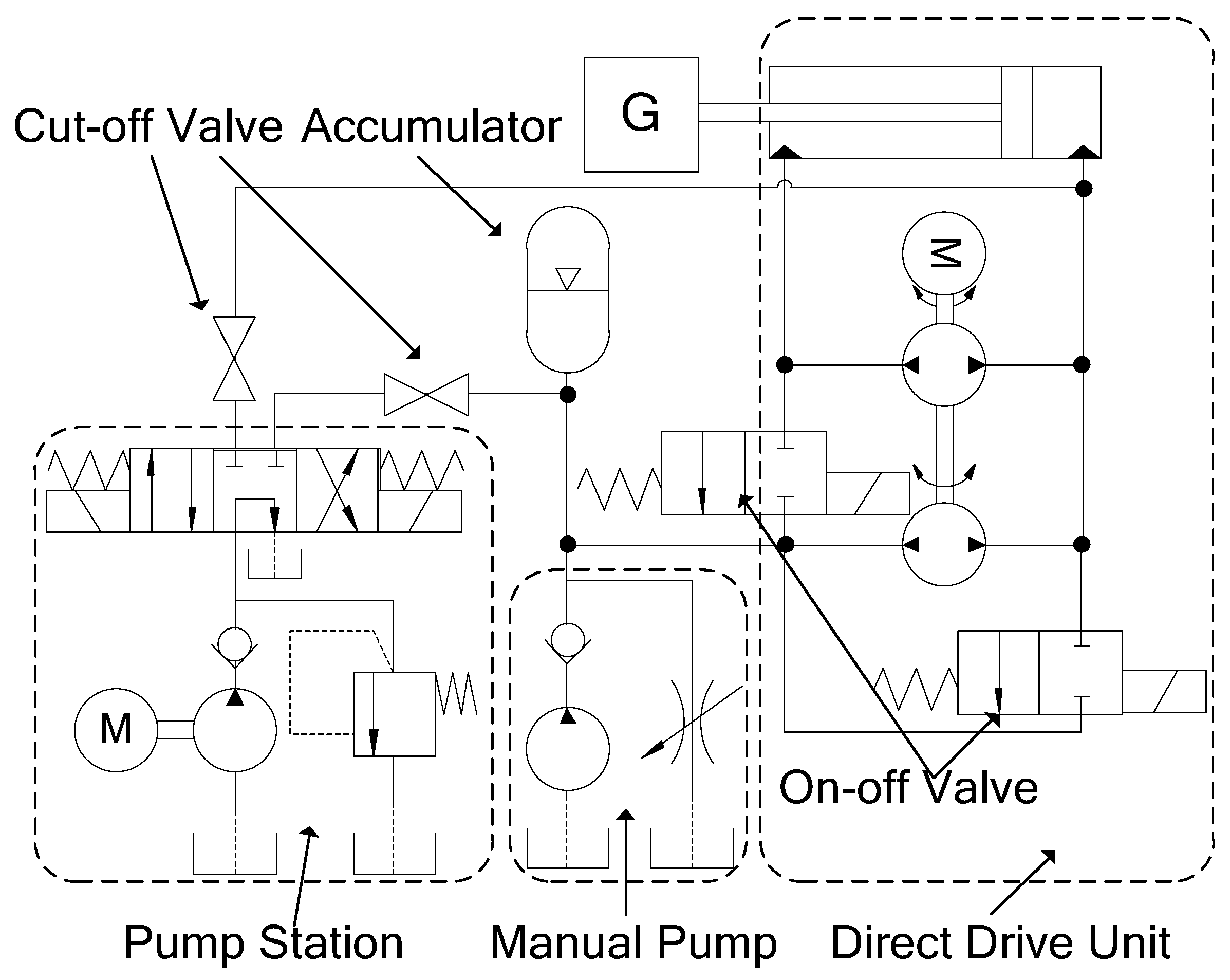
Since the schematic diagram in Figure 2 is merely the basic diagram of the simplified direct drive hydraulic system, and a further expanding to facilitate experiments is also needed, the schematic diagram of the direct drive experimental system is shown in Figure 3.
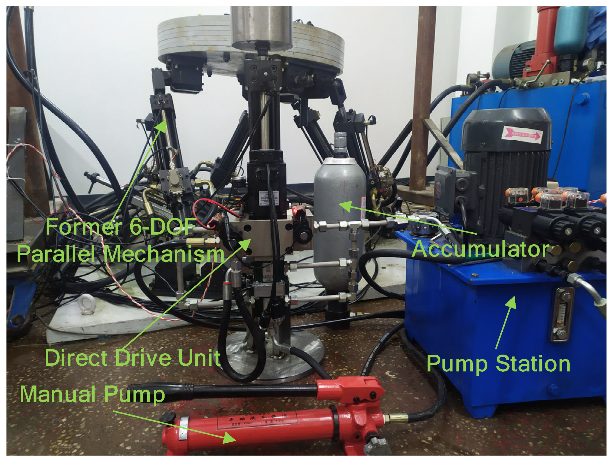
In order to reduce the cost, a manual pump is adopted in the experimental system to adjust the initial pressure and the initial position of the system. A pump station is also added to wash and to exhaust the air of the system. Since the experimental system is actually a single DOF hydraulic system, an accumulator which connect the manual pump and the two cavities of the hydraulic cylinder with two on-off valves is designed to replace the two accumulators in Figure 2. This modification reduces both the complexity of the system and the difficulty of the experiment. Two cut-off valves are used to eliminate the influence of the leakage of the solenoid valve of the pump station. In order to get close to the actual situation, one hydraulic leg of a former hydraulic 6-DOF parallel mechanism is taken down and is applied in the experimental system. According to the above description, the prototype of the experimental system is shown in Figure 4.
5. Results and Discussion
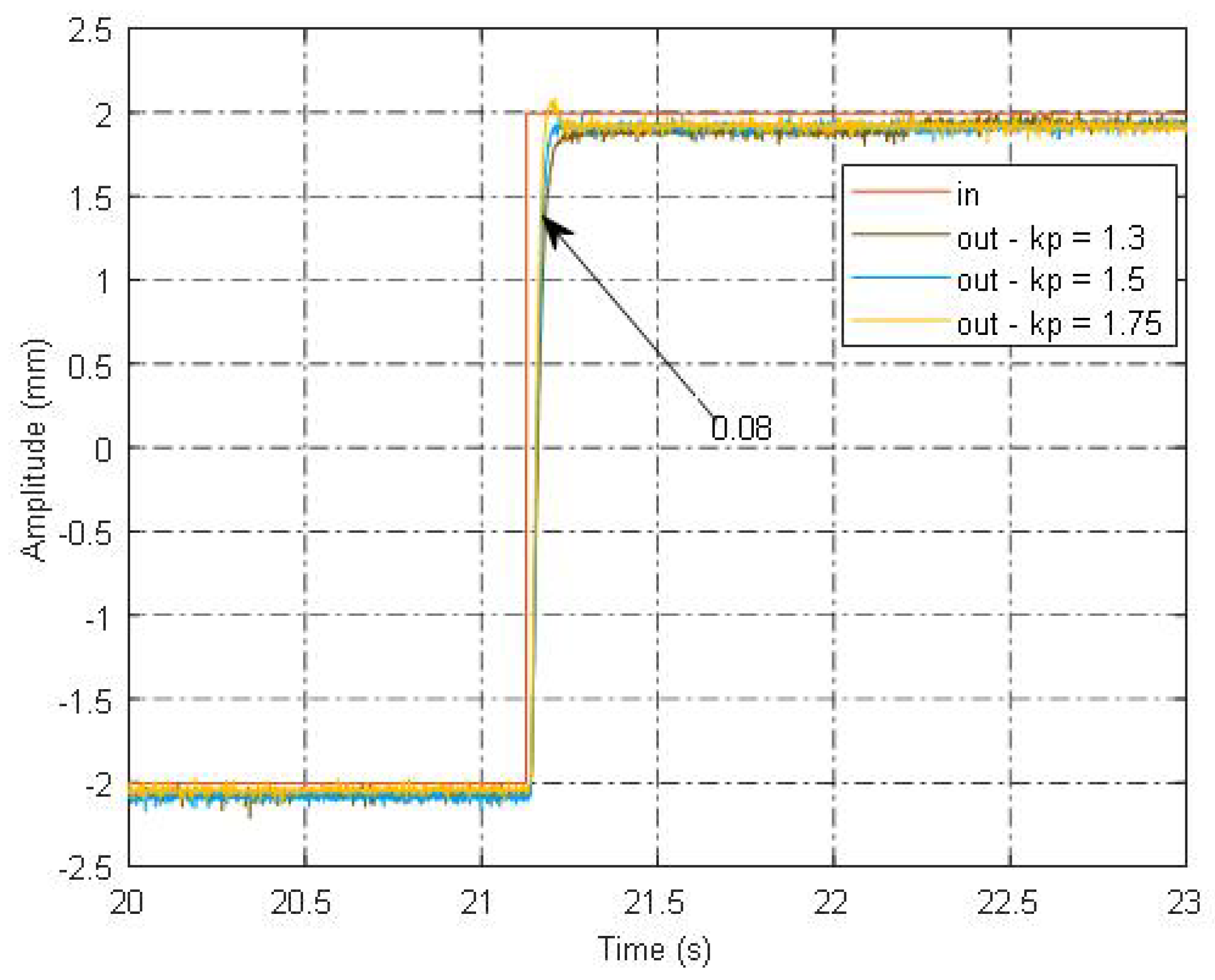
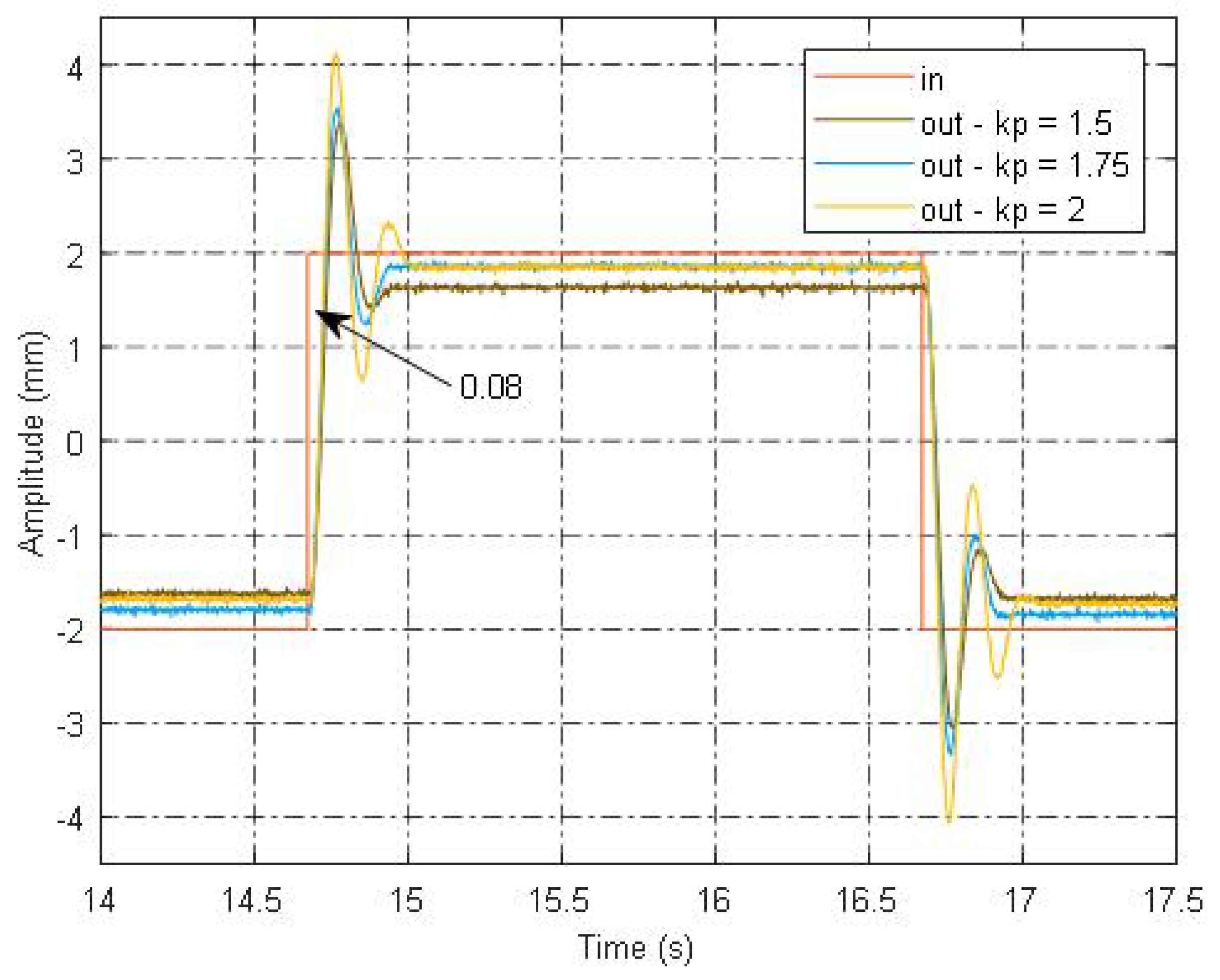
In order to find the key parameters and the dynamic characteristics of the direct drive hydraulic system with the torque mode, the time domain experiments are carried out first and frequency domain experiments are also carried out for full verification. Square wave signals and sinusoidal signals are selected as the input signal of the time domain experiments, and experiments are carried out with both the torque mode and the speed mode for comparison. The response of the system with a square wave signal of 2 mm/0.25 Hz with the speed mode and different proportion control coefficients is shown in Figure 5.
From Figure 5, it is found that the response of the system with the speed mode is good in general, the rise time is quite short (0.08 s), and as the proportion control coefficient increases, the response is better with no overshoot (kp = 1.3, 1.5), and a little overshoot can be found with a larger proportion control coefficient (kp = 1.75), which is in agreement with the transfer function obtained above. It should be noted that although the response of the system moves down as a whole compared with the input signal, the peak-to-valley value of the response does not change, so the above phenomenon is caused by the analog to digital (AD) conversion offset of the servo controller, which will be weaken or even disappear with the complete digitization of the control system. The response of the system with the same input signal and the torque mode is shown in Figure 6.
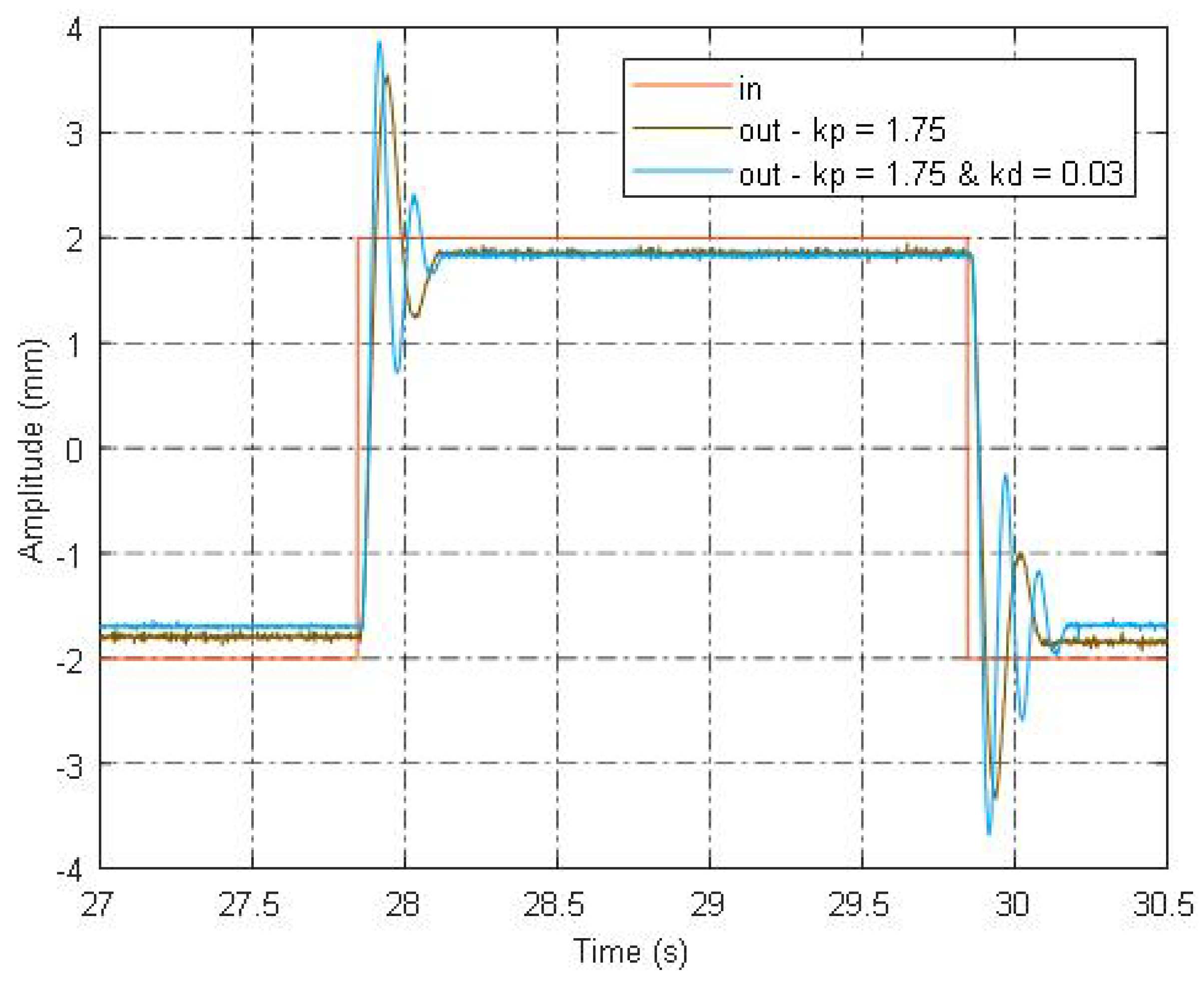
As shown in Figure 6, the response of the system with the torque mode is not satisfied, the rise time is still short and almost the same with that in Figure 5, while large overshoots which magnify as the coefficient increases can be found in all response curves. By comparing Figure 5 and Figure 6, it can be concluded that the damping ratio of the motor-pump second order element is relatively small, which is the reason for the large overshoots. It should be noted that the response of the system with the torque mode does not move down as a whole and the peak-to-valley values of the response curves are smaller compared with the input signal, which is mainly caused by the coulomb friction of the motor-pump unit and is more obvious in the early stage of the system operation and gradually decreases along with time, and this phenomena will not disappear with the complete digitization of the control system. The response of the system with the torque mode and PD control strategy is shown in Figure 7.
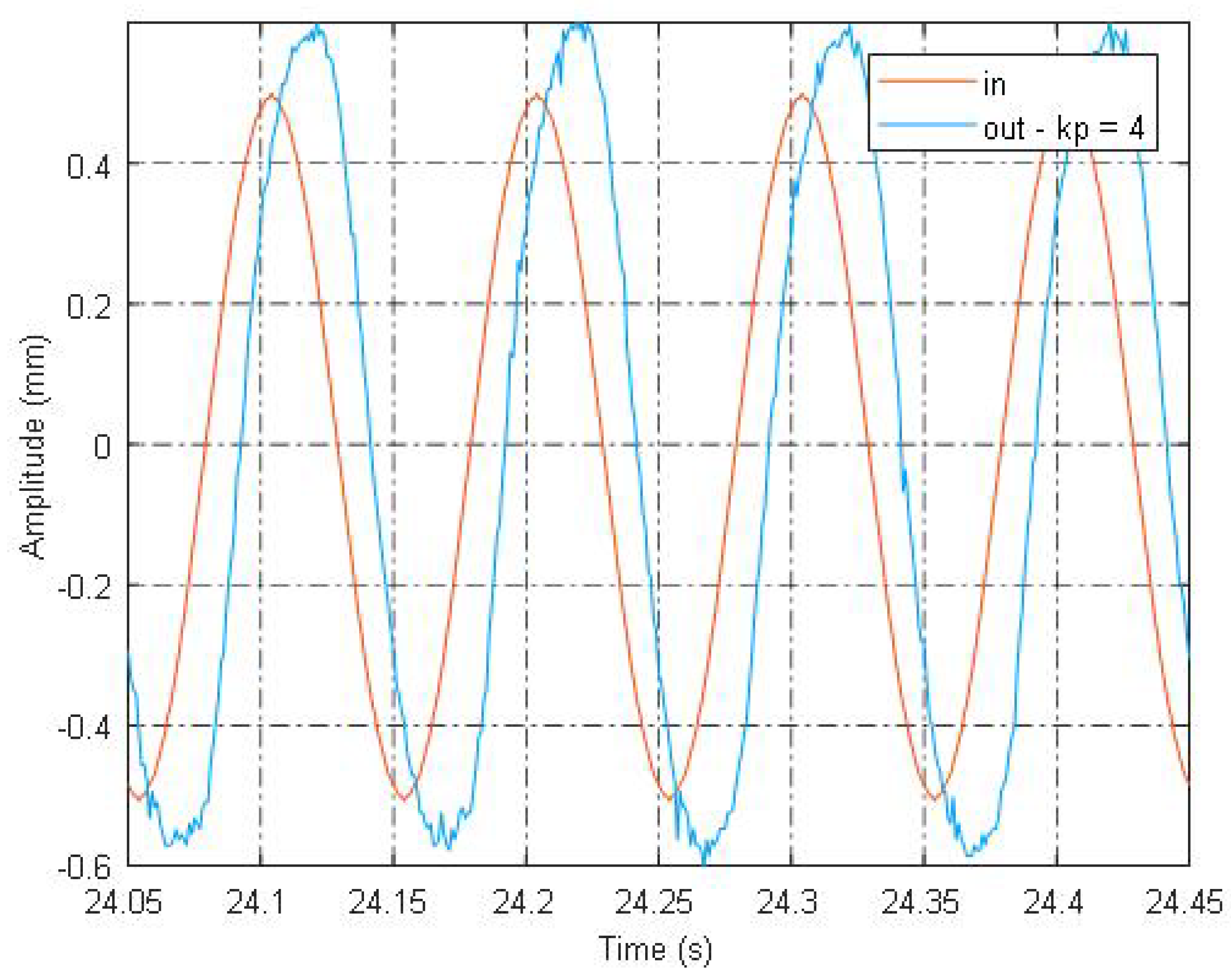
An even stronger shock can be found in the response curve with PD control strategy in Figure 7, compared with that with only proportion control strategy, which is caused by the bad performance of differential operation on step errors, similar results can be found with DPF control strategy, so both PD control strategy and DPF control strategy are not suitable for the direct drive hydraulic system on square wave signals. The dynamic characteristics of the direct drive hydraulic system with the speed mode are shown with the response curve of a sinusoidal input signal of 0.5 mm / 10 Hz with only proportion control strategy and are shown in Figure 8.
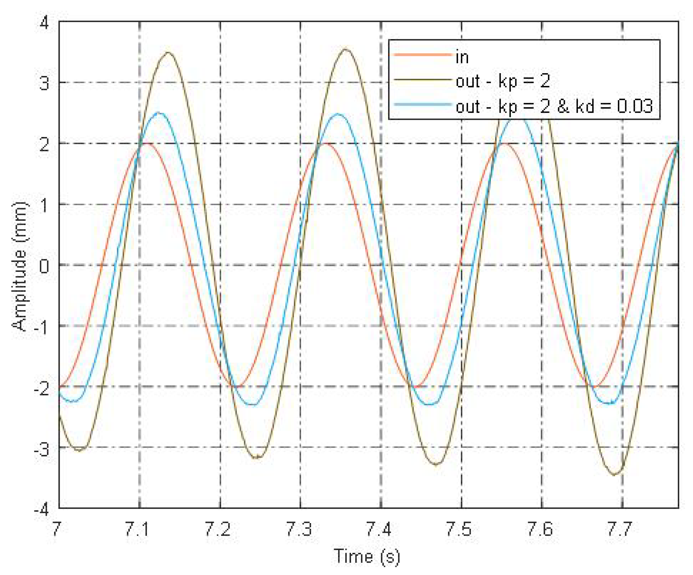
From Figure 8, it is found that a sinusoidal signal of 10 Hz can be easily followed with the speed mode and only proportion control strategy, the dynamic characteristics of the hydraulic system for the direct drive 6-DOF parallel mechanism are very good and are far superior to the ordinary direct drive systems. Since the amplitude of the response curve is bigger than that of the input signal, the second-order element of the system with the speed mode is under-damped. In order to show the dynamic characteristics of the direct drive hydraulic system with the torque mode and the control effect of PD control strategy, a sinusoidal signal of 2 mm / 4.5 Hz is chosen, and the response of the system with the torque mode is shown in Figure 9.
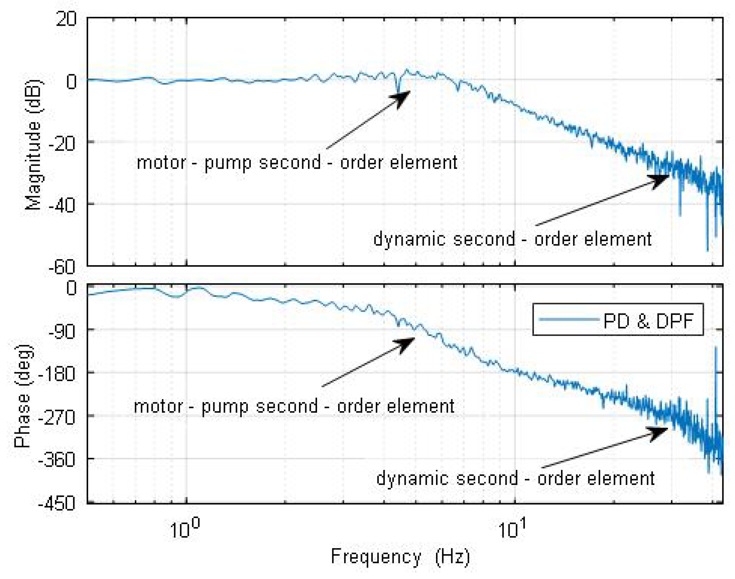
As can be seen in Figure 9, the amplitude of the system response with only proportional control strategy increases gradually and the system is unstable, so the system with only proportion control strategy can not follow even a 4.5 Hz sinusoidal signal, although the amplitude is also increased as PD control strategy used, the stability of the system is guaranteed since the amplitude of the system response does not change over time. Much noise can be found in the signals of pressure sensors, the control effect of DPF control is not obvious. The control ability of PD control strategy and DPF control strategy is illustrated with the bode diagram with both two control strategies used and is shown in Figure 10.
From Figure 10, it can be seen that two second-order elements can be found from Figure 10, which is in agreement with the transfer function model obtained above, and the dynamic characteristics of the system with the torque control mode are mainly determined by the parameters of the motor-pump second-order element of the transfer function, the maximum bandwidth of the direct drive hydraulic system with the torque mode is about 8 Hz with PD control strategy and DPF control strategy. It should be noted that since the maximum bandwidth of the system with proportion control strategy and the torque mode is under 4.5 Hz, the bandwidth of the direct drive system with the torque mode is increased a lot(from under 4.5 Hz to 8 Hz), but the resonant frequencies of the two second-order elements are still far apart, the dynamic characteristics of the system with the torque mode can still be improved, which is not achieved due to the instability of the differential operation of PD control strategy and DPF control strategy, and the signal noise in the data acquisition, but can probably be realized with the complete digitization of the control system and equivalent but more stable and practical control strategies of speed negative feedback and pressure feedback. It is important that sinusoidal signals of 10 Hz can be easily followed with the speed mode with only proportion control strategy which is bigger than the maximum bandwidth with the two control strategies, so the dynamic characteristics of the direct drive hydraulic system with the speed mode which are also very convenient to be realized are generally better than those with the torque mode. This is largely due to the good dynamic characteristics of the speed mode which are guaranteed by the speed closed-loop control of the servo controller, and nether dynamic coupling nor current coupling exists in the single DOF direct drive hydraulic system, this is also the main reason for the wide application of the speed mode.
6. Conclusions
The key parameters and the dynamic characteristics of the direct drive hydraulic system for the direct drive 6-DOF parallel mechanism with the torque mode are studied by the combination of the transfer function and the experiment of the direct drive hydraulic system with the torque mode, compared with those with the speed mode in this paper. The conclusions organized are as follow. The closed-loop transfer function of the direct drive system with the torque mode is composed of two second-order elements and is increased by one order, compared with that with the speed mode. The dynamic characteristics of the system with the torque mode are mainly determined by the parameters of the motor-pump second-order element of the two second-order elements of the closed-loop transfer function, which are both under-damped, the dynamic characteristics of the system with the torque mode can be improved with PD control strategy and DPF control strategy, but practical and effective control methods are still needed. Although the torque-loop locates inside the speed-loop with a faster response, the high-quality dynamic characteristic of the direct drive hydraulic system with the speed mode which is also very convenient to be realized is generally better than those with the torque mode.
Author Contributions
Conceptualization, J.H.; methodology, Z.C.; software, Z.C.; validation, Z.C.; formal analysis, Z.C.; investigation, J.H.; resources, Z.C.; data curation, Z.C.; writing—original draft preparation, Z.C.; writing—review and editing, J.H.; supervision, J.H. All authors have read and agreed to the published version of the manuscript.
Funding
This research received no external funding.
Institutional Review Board Statement
Not applicable.
Informed Consent Statement
Not applicable.
Conflicts of Interest
The authors declare no conflict of interest.
Nomenclature
| and | pressures of the two cavities of the cylinder (Pa) |
| and | piston areas of the two cavities of the cylinder (m2) |
| gravity load (N) | |
| motor torque coefficient (N × m/A) | |
| current of the q axis (A) | |
| moment of inertia of the motor-pump unit (kg × m2) | |
| viscous damping coefficient of the motor-pump unit (N × m × s/rad) | |
| sum displacement of the coaxial gear pump (m3) | |
| and | displacements of the two pump units (m3) |
| load pressure (Pa) | |
| volume efficiency | |
| speed of the motor-pump unit (rpm) | |
| leakage coefficient (m3/Pa) | |
| damping coefficient of the cylinder (N × s/m) | |
| load mass (kg) |
References
- Ehyaei, M.A.; Ahmadi, A.; Rosen, M.A.; Davarpanah, A. Thermodynamic Optimization of a Geothermal Power Plant with a Genetic Algorithm in Two Stages. Processes 2020, 8, 1277. [Google Scholar] [CrossRef]
- Davarpanah, A.; Zareib, M.; Valizadeh, K.; Mirshekaria, B. CFD design and simulation of ethylene dichloride (EDC) thermal cracking reactor. Energy Sources Part A Recovery Util. Environ. Eff. 2019, 41, 1573–1587. [Google Scholar] [CrossRef]
- Yousefifard, M.; Salehi, G.R.; Davarpanah, A. Comparison of Exergy and Advanced Exergy Analysis in Three Different Organic Rankine Cycles. Processes 2020, 8, 586. [Google Scholar]
- Chen, Y.L.; Yan, D.; Zhang, Z.M.; Ning, D.Y.; Gong, Y.J. Static and dynamic characteristics of soft unit based on hydraulic straight drive. J. ZheJiang Univ. (Eng. Sci.) 2019, 53, 1602–1609. [Google Scholar]
- Xu, H.; Du, Z.J.; Shen, J.L.; Wang, L. Characteristics of Power Mechanism for Ultra-high-pressure Hydraulic System with Direct Electric Drive. Zhongguo Jixie Gongcheng 2017, 28, 162–166. [Google Scholar]
- Sell, N.P.; Plummer, A.R.; Hillis, A.J.; Chandel, D. Modelling and calibration of a direct drive hydraulic. In Proceedings of the 12th European Wave and Tidal Energy Conference, Cork, Ireland, 27 August–1 September 2017. [Google Scholar]
- Luo, C.Y.; Yao, J.Y.; Yu, Y.P.; Liu, H.; Xu, Q. Nonlinear Modeling and Analysis of a Dual-stage Direct Drive Actuator. Jixie Gongchen Xuebao 2018, 54, 312–319. [Google Scholar] [CrossRef]
- Wang, X.; Tao, J.F.; Zhang, F.R.; Wu, Y.J.; Liu, C.L. Precision position control of pump-controlled asymmtric cylinder. Zhejiang Daxue Xuebao Gongxueban 2016, 50, 597–602. [Google Scholar]
- Shen, W.; Mai, Y.F.; Su, X.Y.; Zhao, J.B.; Jiang, J.H. A new electric hydraulic actuator adopted the variable displacement pump. Asian J. Control 2016, 18, 178–191. [Google Scholar] [CrossRef]
- Schmidt, L.; Groenkjaer, M.; Pedersen, C.H.; Andersen, O.T. Position Control of an Over-Actuated Direct Hydraulic Cylinder Drive. Control Eng. Pract. 2017, 64, 1–14. [Google Scholar] [CrossRef]
- Minav, T.; Pietola, M.; Filatov, D.M.; Devyatkin, V.A.; Heikkinen, J. Fuzzy control of direct-driven hydraulic drive without conventional oil tank. In Proceedings of the XX IEEE International Conference on Soft Computing and Measurements (SCM), St. Petersburg, Russia, 24–26 May 2017; Institute of Electrical and Electronics Engineers (IEEE): Piscataway, NJ, USA, 2017; pp. 444–447. [Google Scholar]
- Helian, B.; Chen, Z.; Yao, B. Precision Motion Control of a Servomotor-Pump Direct-Drive Electrohydraulic System With a Nonlinear Pump Flow Mapping. IEEE Trans. Ind. Electron. 2019, 67, 8638–8648. [Google Scholar] [CrossRef]
- Ko, T.; Kaminaga, H.; Nakamura, Y. Key design parameters of a few types of electro-hydrostatic actuators for humanoid robots. Adv. Robot. 2018, 32, 1241–1252. [Google Scholar] [CrossRef]
- Ko, T.; Kaminaga, H.; Nakamura, Y. Current-pressure-position triple-loop feedback control of electro-hydrostatic actuators for humanoid robots. Adv. Robot. 2018, 32, 1269–1284. [Google Scholar] [CrossRef]
- Rehman, W.U.; Wang, X.; Wang, S.; Azhar, I. Motion synchronization of HA/EHA system for a large civil aircraft by using adaptive control. In Proceedings of the 2016 IEEE Chinese Guidance, Navigation and Control Conference (CGNCC), Nanjing, China, 12–14 August 2016; Institute of Electrical and Electronics Engineers (IEEE): Piscataway, NJ, USA, 2016; pp. 1486–1491. [Google Scholar]
- Rehman, W.U.; Wang, S.; Wang, X.; Shi, C.; Zhang, C.; Tomovic, M. Adaptive control for motion synchronization of HA/EHA system by using modified MIT rule. In Proceedings of the 2016 IEEE 11th Conference on Industrial Electronics and Applications (ICIEA), Hefei, China, 5–7 June 2016; Institute of Electrical and Electronics Engineers (IEEE): Piscataway, NJ, USA, 2016. [Google Scholar]
- Zad, H.S.; Ulasyar, A.; Zohaib, A. Robust Model Predictive position Control of direct drive electro-hydraulic servo system. In Proceedings of the 2016 International Conference on Intelligent Systems Engineering (ICISE), Islamabad, Pakistan, 15–17 January 2016; Institute of Electrical and Electronics Engineers (IEEE): Piscataway, NJ, USA, 2016. [Google Scholar]
- Kou, R.F.; Xu, J.N.; Liu, D.P.; Zhang, K.; Sun, K. Study on dual sliding mode control of EHA active suspensions. Zhongguo Jixie Gongcheng 2019, 30, 42–48, 53. [Google Scholar]
- Jiang, J.H.; Ge, Z.H.; Yang, C.; Liang, H.J. Differentiator-based discrete variable structure controller for direct drive electro-hydraulic servo system. Jilin Daxue Xuebao Gongxueban 2018, 48, 1492–1499. [Google Scholar]
- Li, Z.; Shang, Y.; Jiao, Z.; Lin, Y.; Wu, S.; Li, X. Analysis of the dynamic performance of an electro-hydrostatic actuator and improvement methods. Chin. J. Aeronaut. 2018, 31, 2312–2320. [Google Scholar] [CrossRef]
- Zhang, C. PD Plus Dynamic Pressure Feedback Control for a Direct Drive Stewart Manipulator. Energies 2020, 13, 1125. [Google Scholar] [CrossRef] [Green Version]
Figure 1.
The structure and the direct drive hydraulic system of the direct drive 6-DOF (6 degree of freedom) parallel mechanism.
Figure 1.
The structure and the direct drive hydraulic system of the direct drive 6-DOF (6 degree of freedom) parallel mechanism.

Figure 2.
Schematic diagram of the simplified single DOF(degree of freedom) direct drive hydraulic system.
Figure 2.
Schematic diagram of the simplified single DOF(degree of freedom) direct drive hydraulic system.

Figure 3.
Schematic diagram of the direct drive experimental system.

Figure 4.
Prototype of the experimental system.

Figure 5.
The square wave signal response diagram of the system with the speed mode.

Figure 6.
The square wave signal response diagram of the system with the torque mode.

Figure 7.
The response diagram of the system with the torque mode and PD (proportion differentiation) control strategy.
Figure 7.
The response diagram of the system with the torque mode and PD (proportion differentiation) control strategy.

Figure 8.
The sinusoidal signal response diagram of the system with the speed mode and proportion control strategy.
Figure 8.
The sinusoidal signal response diagram of the system with the speed mode and proportion control strategy.

Figure 9.
The sinusoidal signal response diagram of the system with the torque mode.

Figure 10.
Bode diagram of the system with both PD control strategy and DPF (dynamic pressure feedback) control strategy.
Figure 10.
Bode diagram of the system with both PD control strategy and DPF (dynamic pressure feedback) control strategy.

Publisher’s Note: MDPI stays neutral with regard to jurisdictional claims in published maps and institutional affiliations. |
© 2021 by the authors. Licensee MDPI, Basel, Switzerland. This article is an open access article distributed under the terms and conditions of the Creative Commons Attribution (CC BY) license (http://creativecommons.org/licenses/by/4.0/).
Share and Cite
MDPI and ACS Style
Zhang, C.; Jiang, H. Experimental Study of the Direct Drive Hydraulic System with the Torque Mode. Energies 2021, 14, 941. https://0-doi-org.brum.beds.ac.uk/10.3390/en14040941
AMA Style
Zhang C, Jiang H. Experimental Study of the Direct Drive Hydraulic System with the Torque Mode. Energies. 2021; 14(4):941. https://0-doi-org.brum.beds.ac.uk/10.3390/en14040941
Chicago/Turabian StyleZhang, Chenyang, and Hongzhou Jiang. 2021. "Experimental Study of the Direct Drive Hydraulic System with the Torque Mode" Energies 14, no. 4: 941. https://0-doi-org.brum.beds.ac.uk/10.3390/en14040941
Note that from the first issue of 2016, this journal uses article numbers instead of page numbers. See further details here.