
Varying Ignition Quality of a Fuel for a HCCI Engine Using a Photochemically-Controlled Additive: The Development of a ‘Smart’ Fuel


Abstract
:1. Introduction
Numerical Simultation
2. Experimental Methods
2.1. Fuel Production and Analysis
2.1.1. Pen-Ray Lamp Experiments
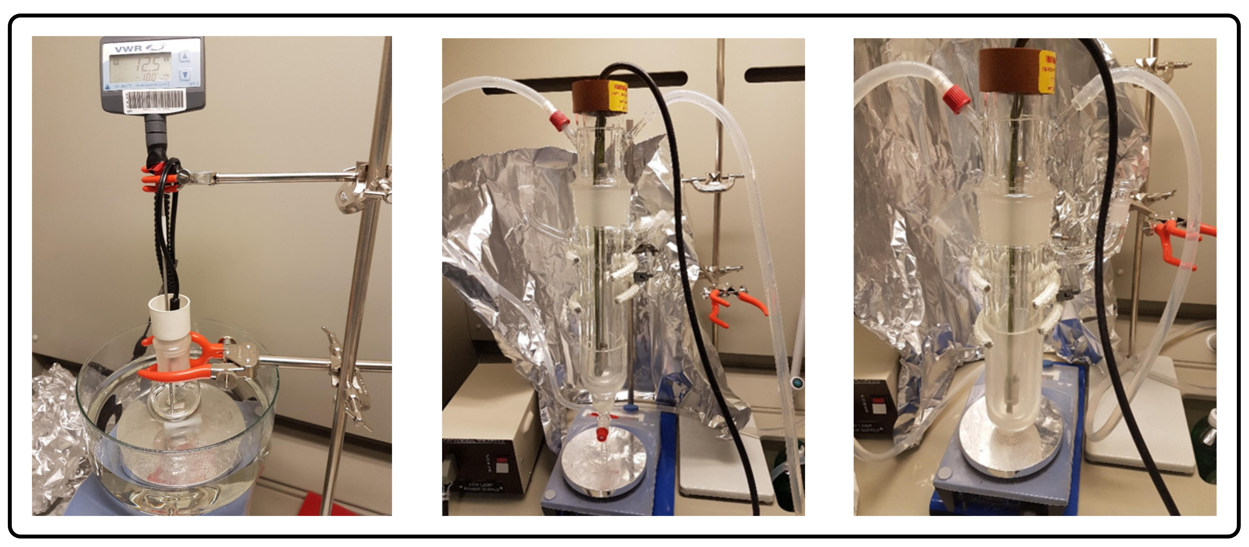
2.1.2. Immersion Well Reactor Experiments
2.1.3. Fuel Analysis
2.2. HCCI Testing
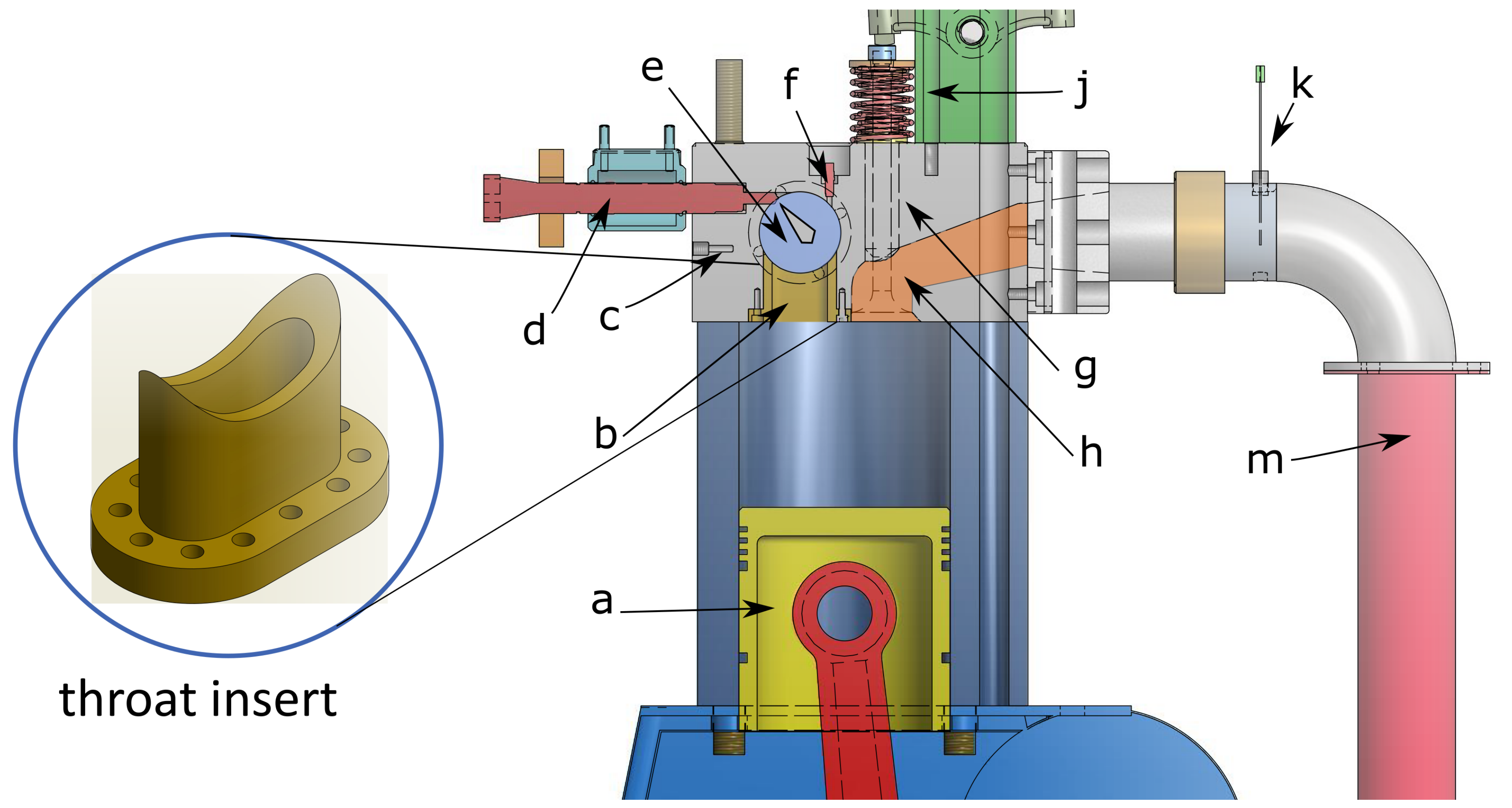
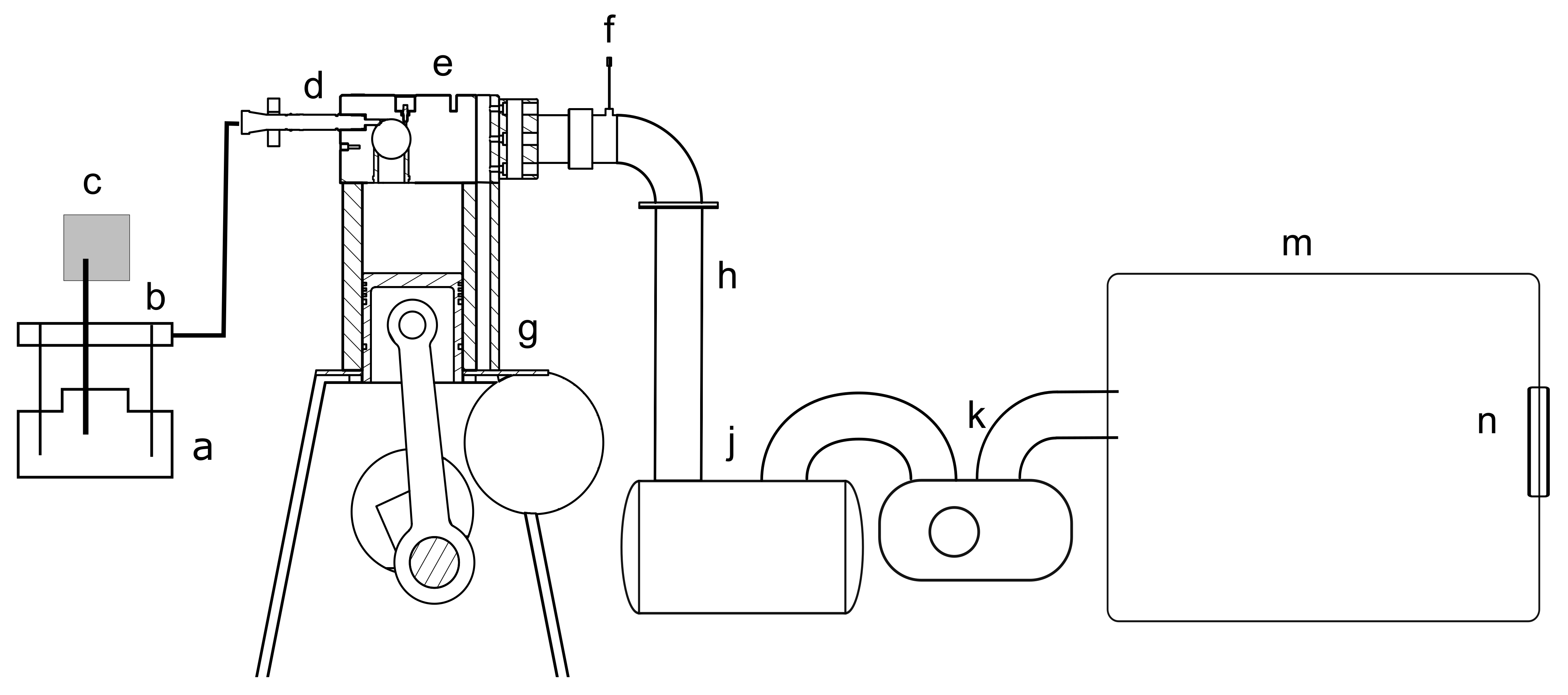
2.2.1. Optically Accessible Compression Ignition Chamber
2.2.2. Optical Set-Up
3. Results and Discussions
3.1. Fuel Characterization
3.1.1. Pen-Ray Lamp Experiments
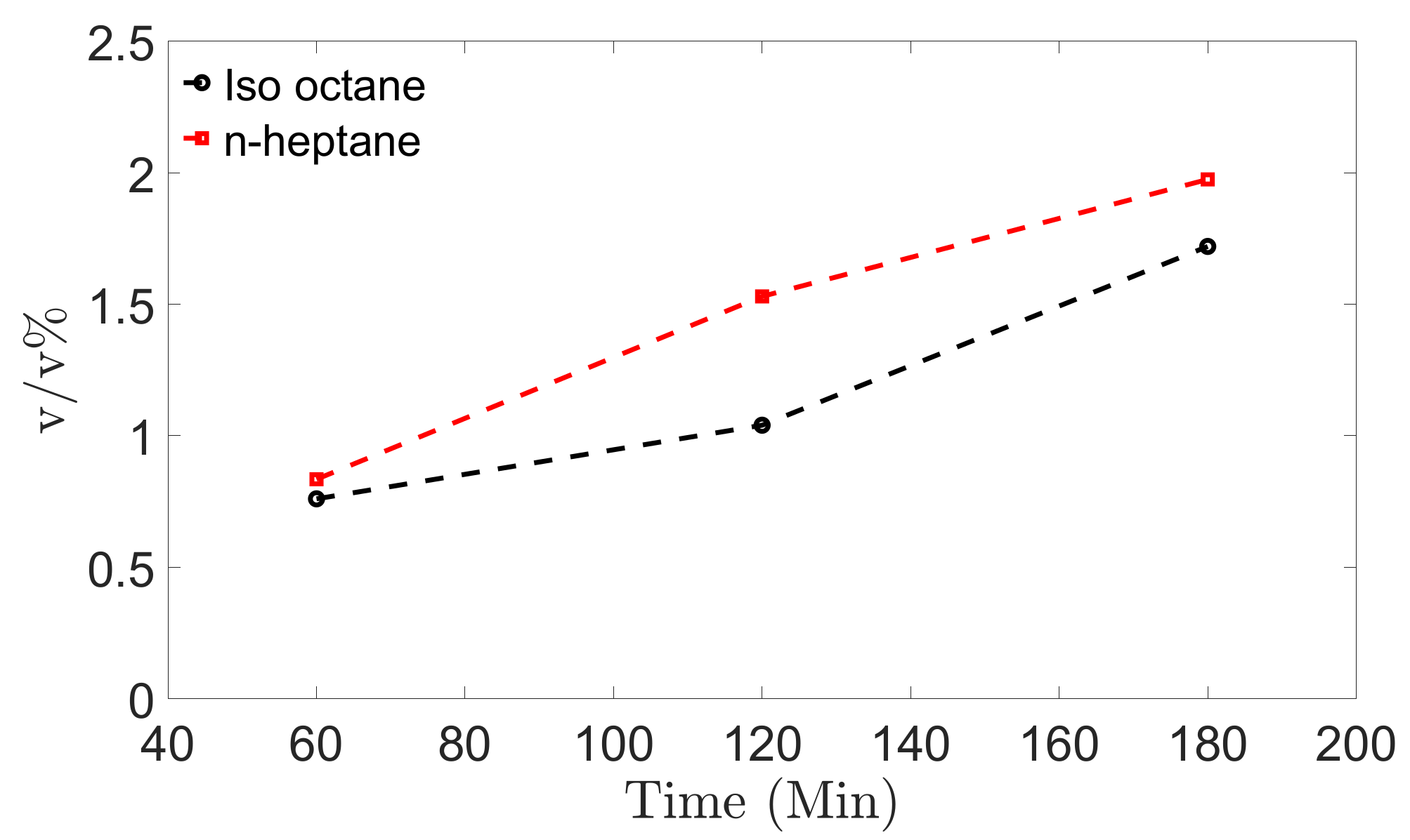
3.1.2. Immersion Well Reactor Experiments
3.2. HCCI Testing
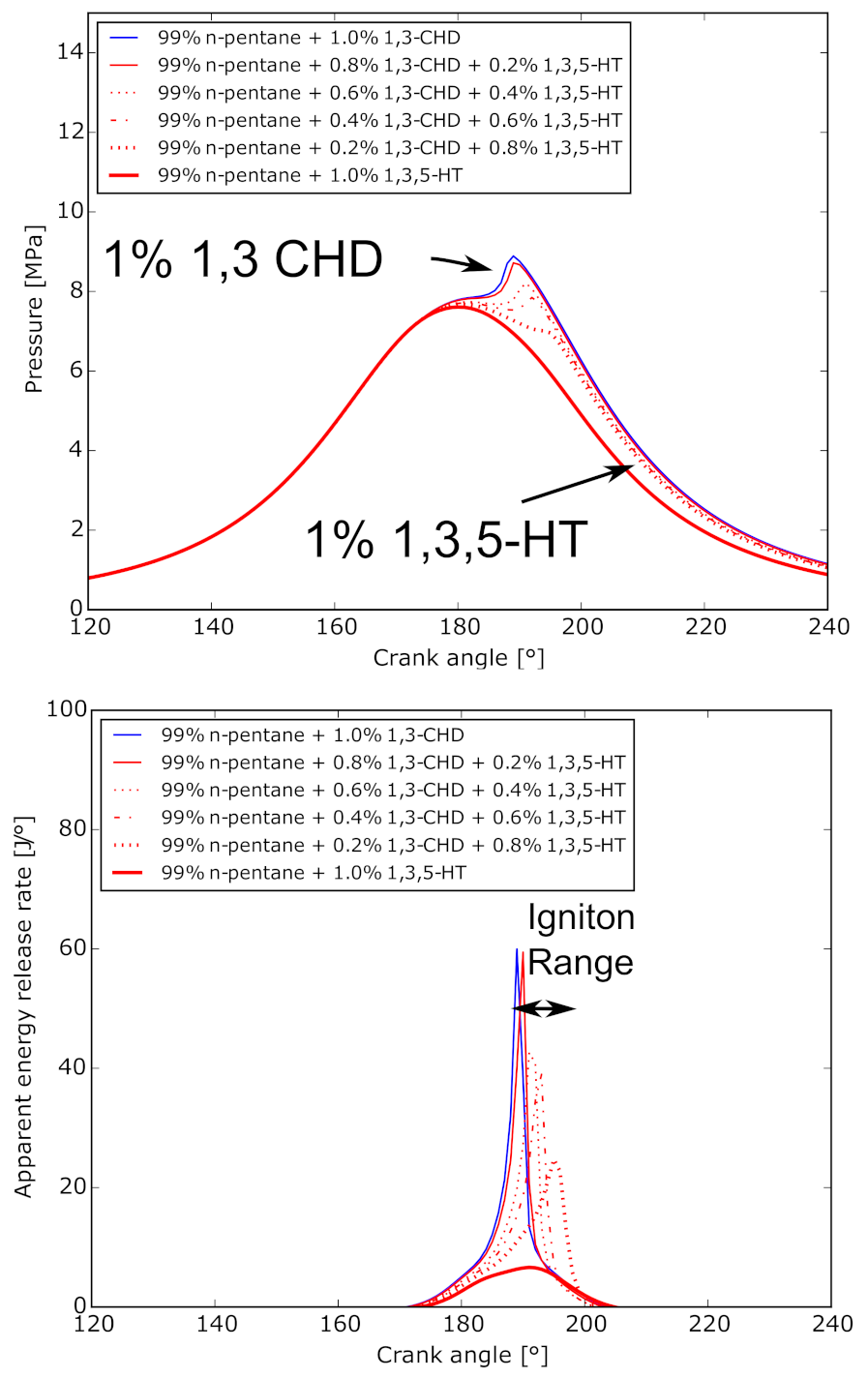
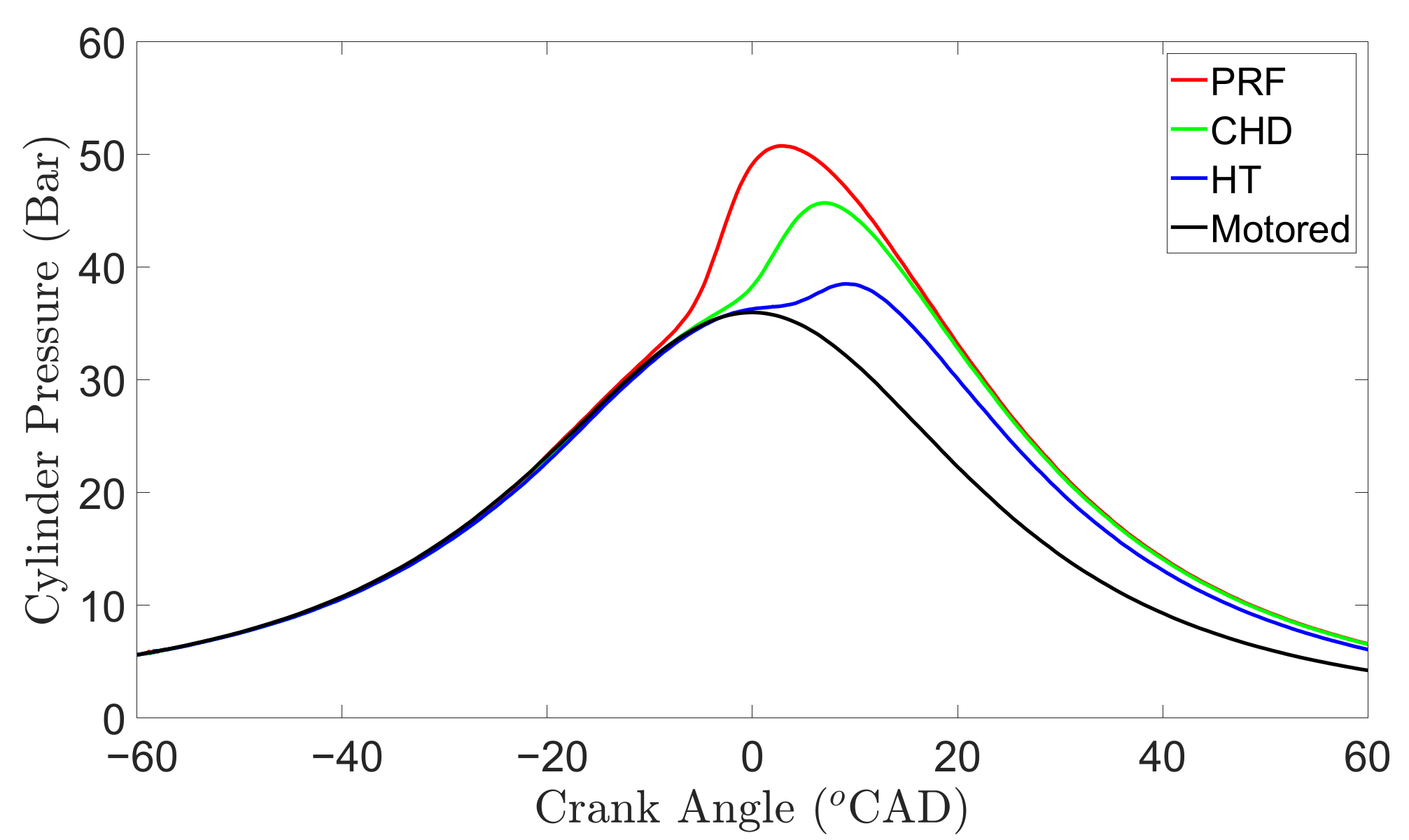
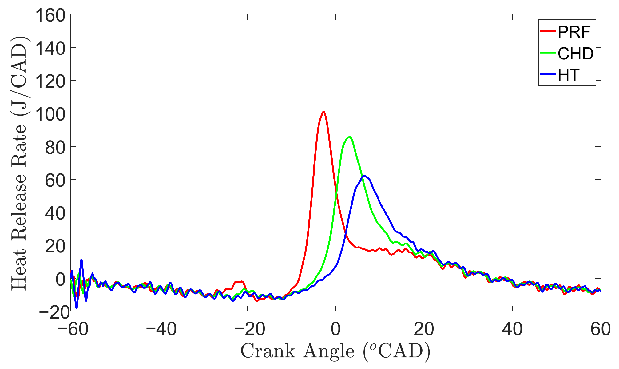
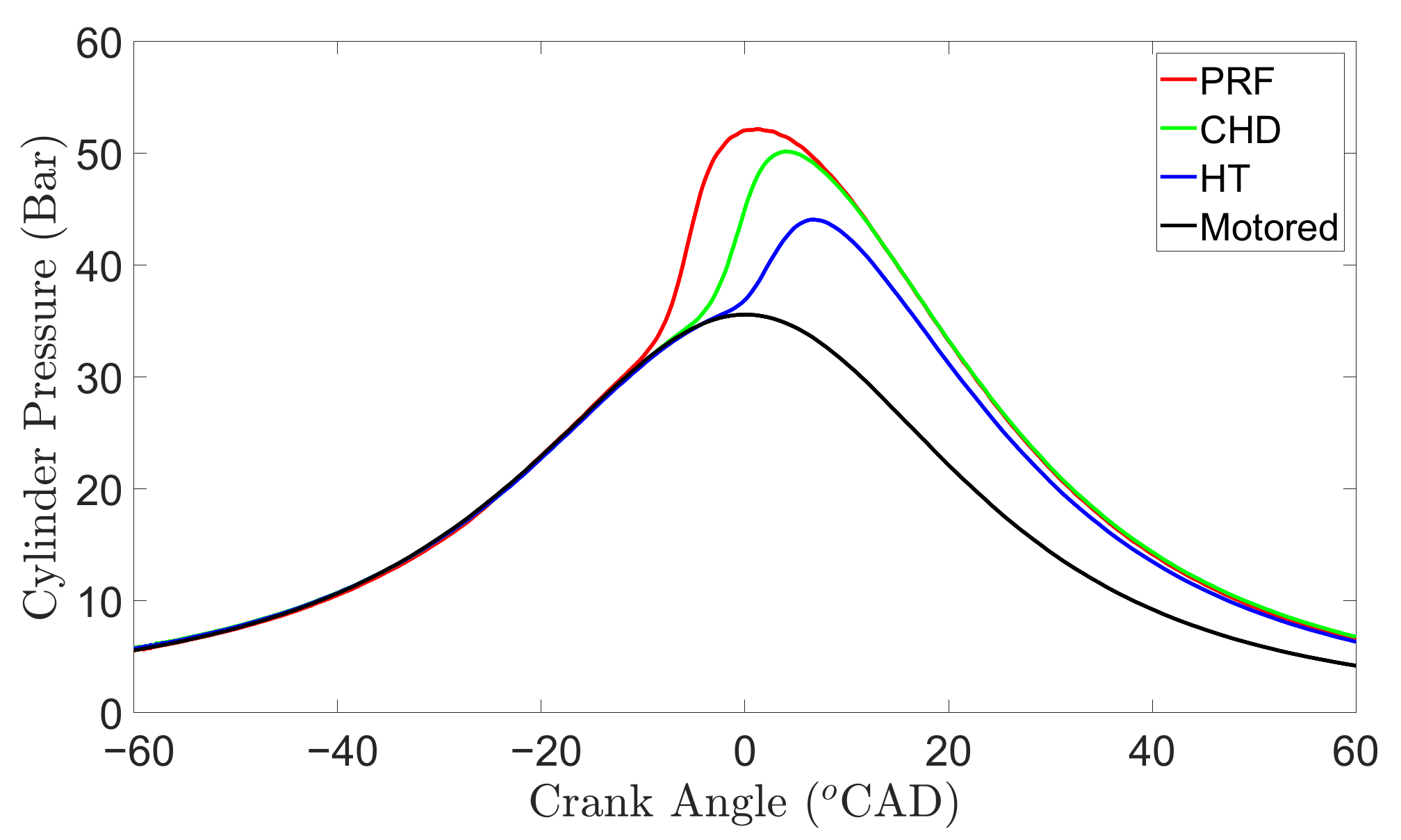
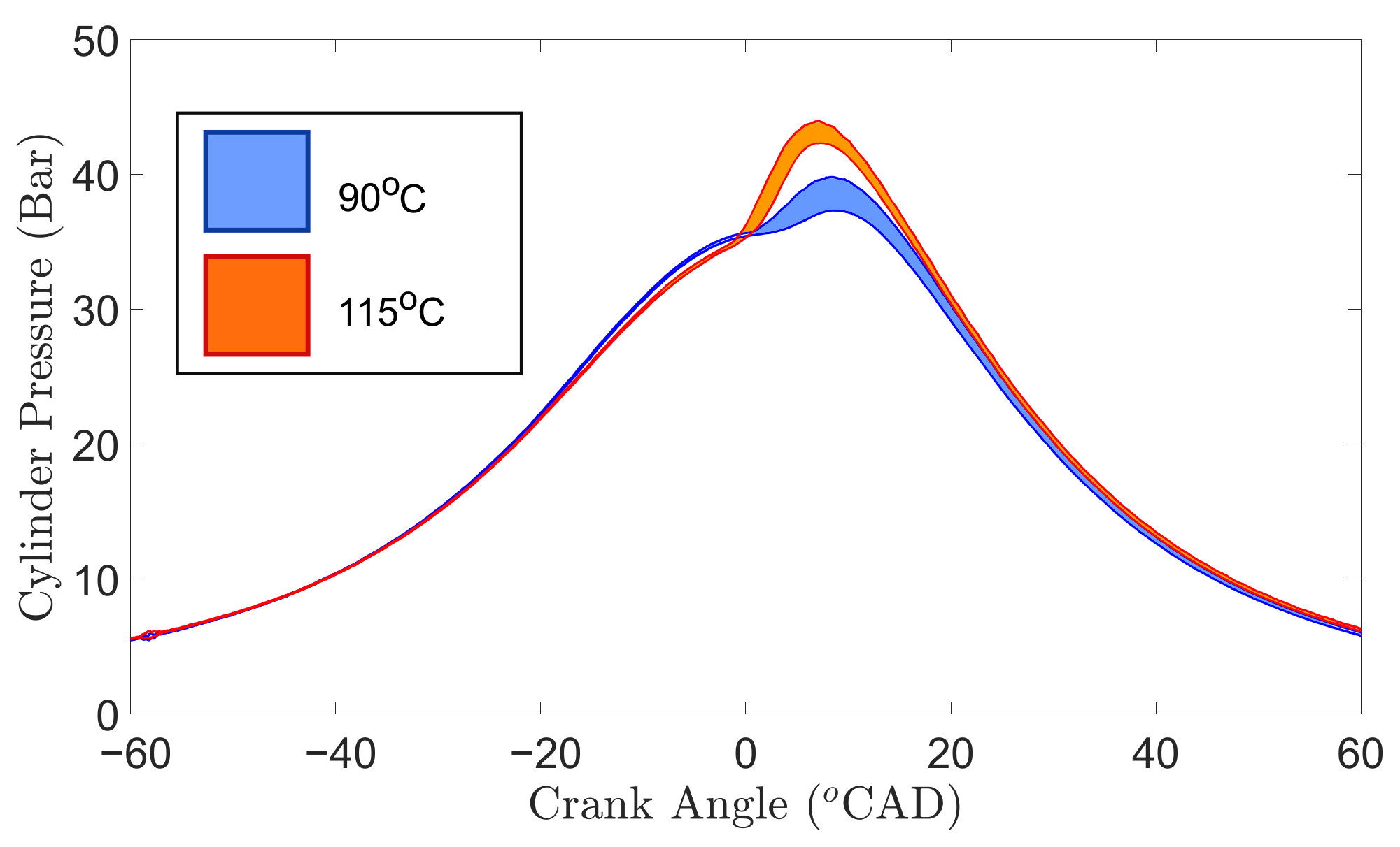
3.2.1. Combustion Pressures and HRR
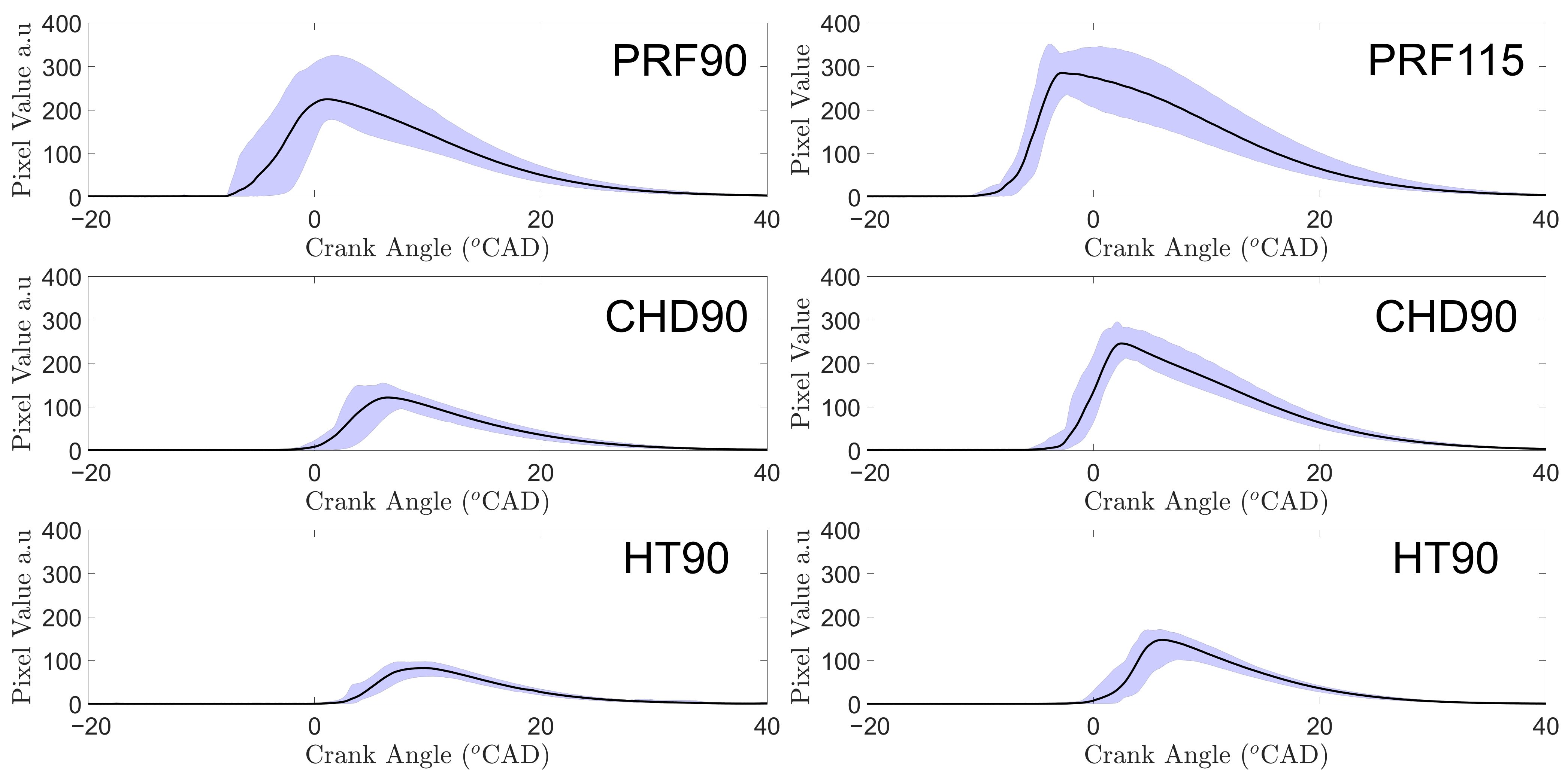
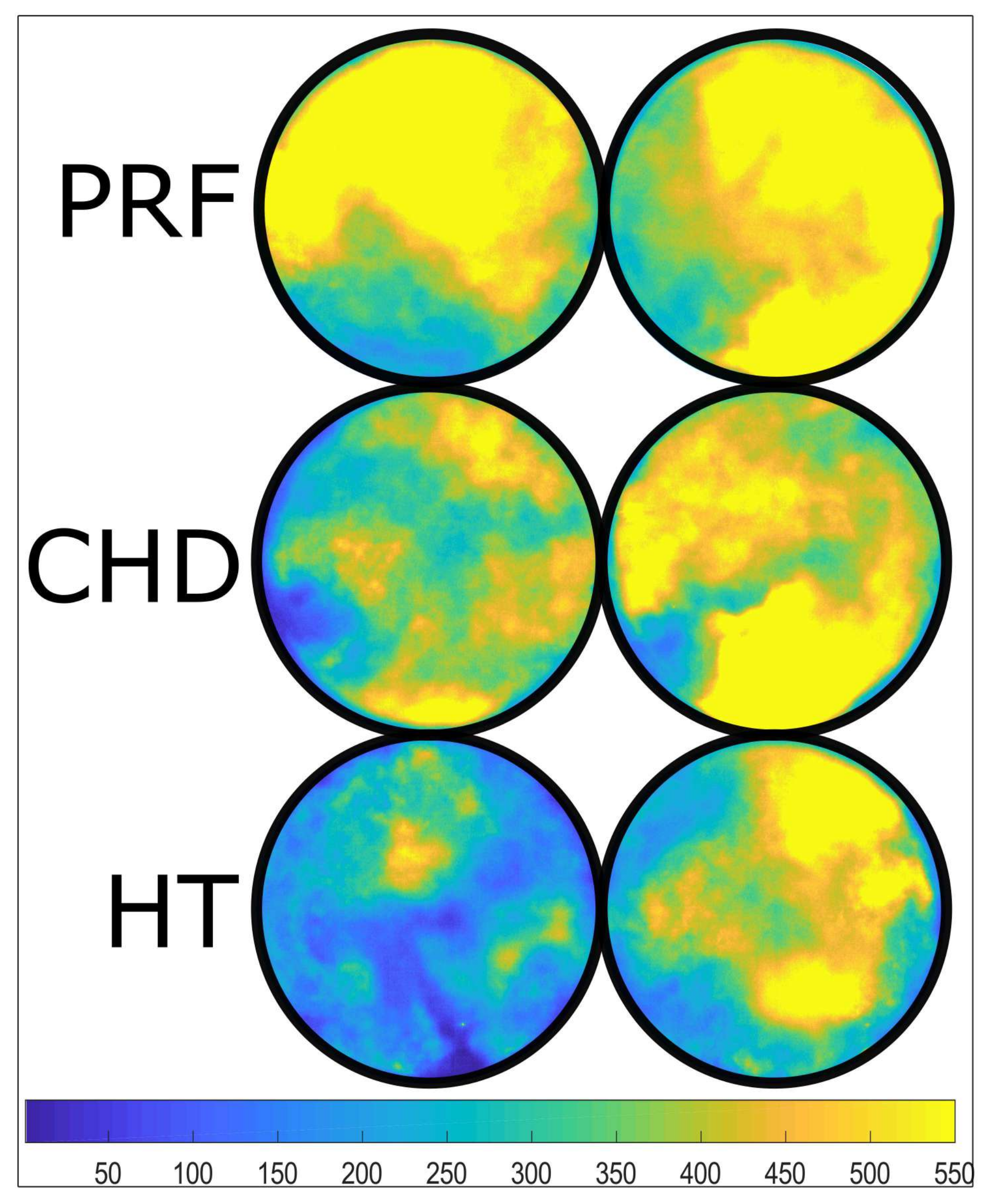
3.2.2. Optical Results
4. Summary and Conclusions
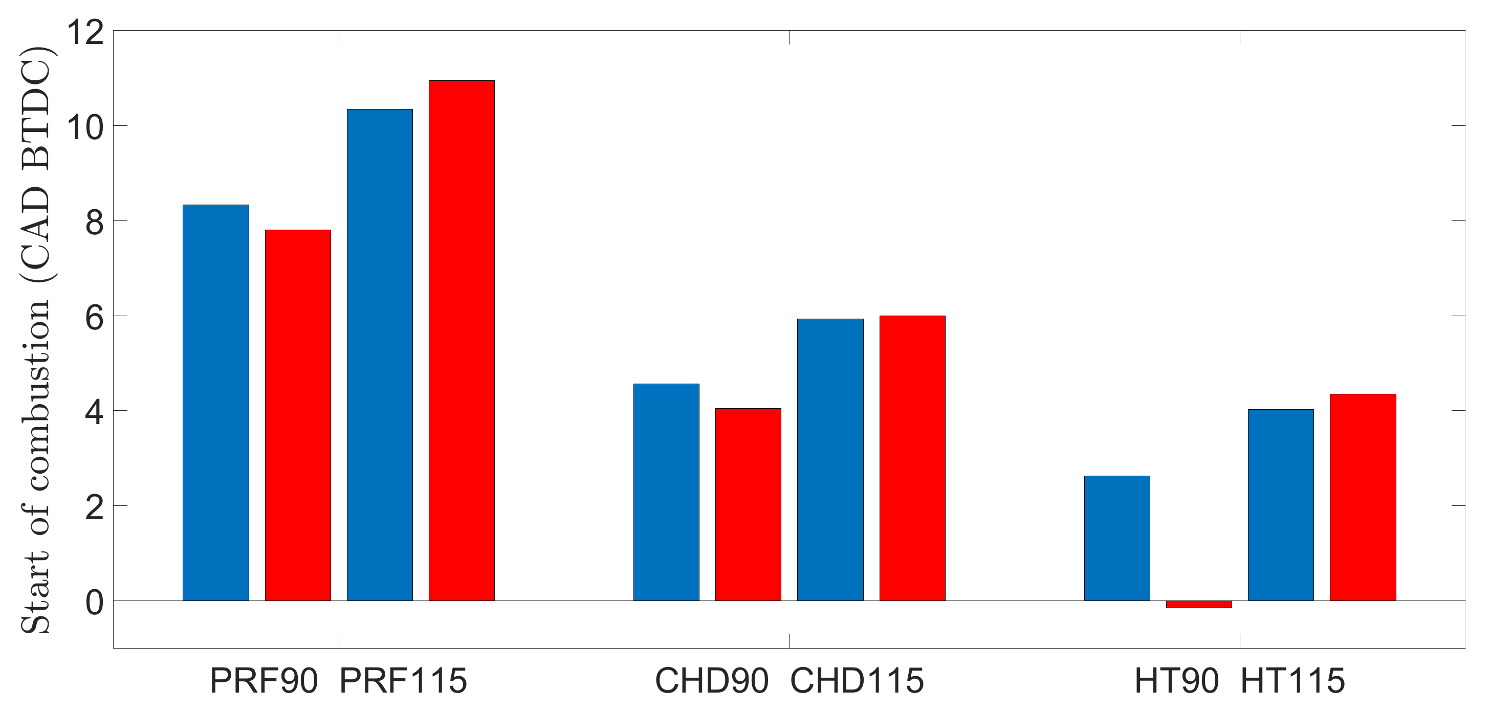
- Increasing T advanced the start of combustion (SOC).
- CHD addition retarded the SOC and reduced heat release rate compared with the PRF.
- The HT containing PRF had a retarded SOC and heat release rate was significantly reduced compared with both PRF and CHD fuels.
- CHD and HT reduced flame intensity as observed by the camera.
Author Contributions
Funding
Data Availability Statement
Conflicts of Interest
Abbreviations
| CAD | crank angle degrees |
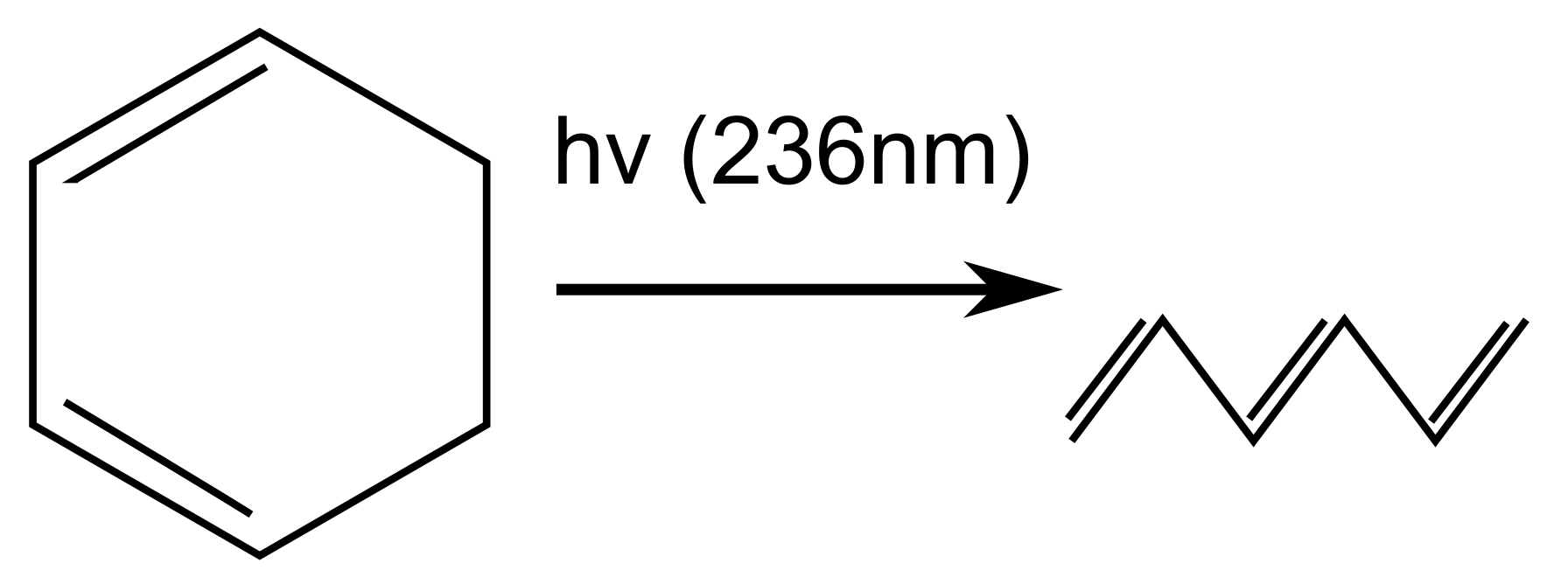
| CHD | 1,3-cyclohexadiene |
| CI | compression ignition |
| DAQ | data acquisition |
| EGR | exhaust gas re-circulation |
| ET | engine test |
| HCCI | homogeneous charge compression ignition |
| HT | 1,3,5-hexatriene |
| ICE | internal combustion engine |
| PRF | primary reference fuel |
| RCCI | reaction controlled compression ignition |
| rpm | revs per minute |
| SI | spark ignition |
| SOC | start of combustion |
| TDC | top dead center |
| UV | ultraviolet |
References
- Reitz, R.D. Directions in internal combustion engine research. Combust. Flame 2013, 160, 1–8. [Google Scholar] [CrossRef]
- Dec, J.E. Advanced compression-ignition engines, understanding the in-cylinder processes. Proc. Combust. Inst. 2009, 32, 2727–2742. [Google Scholar] [CrossRef]
- Musculus, M.P.; Miles, P.C.; Pickett, L.M. Conceptual models for partially premixed low-temperature diesel combustion. Prog. Energy Combust. Sci. 2013, 39, 246–283. [Google Scholar] [CrossRef]
- Reitz, R.D.; Duraisamy, G. Review of high efficiency and clean reactivity controlled compression ignition (RCCI) combustion in internal combustion engines. Prog. Energy Combust. Sci. 2015, 46, 12–71. [Google Scholar] [CrossRef] [Green Version]
- Lu, X.; Han, D.; Huang, Z. Fuel design and management for the control of advanced compression-ignition combustion modes. Prog. Energy Combust. Sci. 2011, 37, 741–783. [Google Scholar] [CrossRef]
- Yao, M.; Zheng, Z.; Liu, H. Progress and recent trends in homogeneous charge compression ignition (HCCI) engines. Prog. Energy Combust. Sci. 2009, 35, 398–437. [Google Scholar] [CrossRef]
- Splitter, D.A.; Reitz, R.D. Fuel reactivity effects on the efficiency and operational window of dual-fuel compression ignition engines. Fuel 2014, 118, 163–175. [Google Scholar] [CrossRef]
- Kokjohn, S.L.; Musculus, M.P.; Reitz, R.D. Evaluating temperature and fuel stratification for heat-release rate control in a reactivity-controlled compression-ignition engine using optical diagnostics and chemical kinetics modeling. Combust. Flame 2015, 162, 2729–2742. [Google Scholar] [CrossRef] [Green Version]
- Tong, L.; Wang, H.; Zheng, Z.; Reitz, R.; Yao, M. Experimental study of RCCI combustion and load extension in a compression ignition engine fueled with gasoline and PODE. Fuel 2016, 181, 878–886. [Google Scholar] [CrossRef]
- Eyal, A.; Tartakovsky, L. Second-law analysis of the reforming-controlled compression ignition. Appl. Energy 2020, 263, 114622. [Google Scholar] [CrossRef]
- Starck, L.; Lecointe, B.; Forti, L.; Jeuland, N. Impact of fuel characteristics on HCCI combustion: Performances and emissions. Fuel 2010, 89, 3069–3077. [Google Scholar] [CrossRef]
- Yao, M.; Chen, Z.; Zheng, Z.; Zhang, B.; Xing, Y. Study on the controlling strategies of homogeneous charge compression ignition combustion with fuel of dimethyl ether and methanol. Fuel 2006, 85, 2046–2056. [Google Scholar] [CrossRef]
- Schonborn, A.; Hellier, P.; Aliev, A.E.; Ladommatos, N. Ignition control of homogeneous-charge compression ignition (HCCI) combustion through adaptation of the fuel molecular structure by reaction with ozone. Fuel 2010, 89, 3178–3184. [Google Scholar] [CrossRef]
- Goldsmith, J.E.M. Photochemical effects in two-photon-excited fluorescence detection of atomic oxygen in flames. Appl. Opt. 1987, 26, 3566–3572. [Google Scholar] [CrossRef] [PubMed]
- Bezgin, L.V.; Kopchenov, V.I.; Kuleshov, P.S.; Titova, N.S.; Starik, A.M. Numerical study of combustion initiation in a supersonic flow of H2 and air mixture by resonance laser radiation. J. Phys. D Appl. Phys. 2012, 45, 085401. [Google Scholar] [CrossRef]
- Schonborn, A. A ‘smart’ fuel of photochemically-controlled reactivity. Fuel 2016, 165, 389–396. [Google Scholar] [CrossRef]
- Minnaard, N.G.; Havinga, E. Some aspects of the solution photochemistry of 1,3-cyclohexadiene, (Z)- and (E)-1,3,5-hexatriene. Recl. Trav. Chim. Pays Bas 1973, 92, 1315–1320. [Google Scholar] [CrossRef]
- Bjørgen, K.O.P.; Emberson, D.R.; Lovas, T. Diffuse Back-Illuminated Extinction Imaging of Soot: Effects of Beam Steering and Flame Luminosity. In Proceedings of the International Powertrains, Fuels & Lubricants Meeting, San Antonio, TX, USA, 22–24 January 2019; SAE International: Warrendale, PA, USA, 2019. [Google Scholar]
- Schönborn, A. Autoignition Control of Fuel and Air Mixtures Using Photochemical Isomerization. Energy Fuels 2018, 32, 12930–12935. [Google Scholar] [CrossRef]
- Sirjean, B.; Buda, F.; Hakka, H.; Glaude, P.; Fournet, R.; Warth, V.; Battin-Leclerc, F.; Ruiz-Lopez, M. The autoignition of cyclopentane and cyclohexane in a shock tube. Proc. Combust. Inst. 2007, 31, 277–284. [Google Scholar] [CrossRef] [Green Version]


| Experiment | Solvent | CHD | Irradiation |
|---|---|---|---|
| (Solution) | v/v% | v/v% | Time (min) |
| ISO0 | 95 Iso | 5 | 0 |
| ISO60 | 95 Iso | 5 | 60 |
| ISO120 | 95 Iso | 5 | 120 |
| ISO180 | 95 Iso | 5 | 180 |
| HEP0 | 95 Hep | 5 | 0 |
| HEP60 | 95 Hep | 5 | 60 |
| HEP120 | 95 Hep | 5 | 120 |
| HEP180 | 95 Hep | 5 | 180 |
| ET | 85 wt% Iso + | 5 wt% | 240 |
| (engine tests) | 10 wt% Hep |
| 1,3,5-Hexatriene Concentration | w/v% | v/v% |
|---|---|---|
| 1 min iso-octane | 0.014 | 0.02 |
| 120 min iso-octane | 1.16 | 1.61 |
| 120 min n-heptane | 1.11 | 1.54 |
| 120 min iso-octane | ||
| analyzed 8 days later | 1.05 | 1.46 |
| Cetane | CHD | |||
|---|---|---|---|---|
| Solution | w/v% | v/va% | Number | Conversion |
| % | ||||
| ISO0 | 0 | 0 | 14.9 | 0 |
| ISO60 | 0.55 | 0.76 | 14.0 | 15.2 |
| ISO120 | 0.75 | 1.04 | 15.5 | 20.8 |
| ISO180 | 1.24 | 1.72 | 14.6 | 34.4 |
| HEP0 | 0 | 0 | 49.3 | 0 |
| HEP60 | 0.6 | 0.83 | 49.7 | 16.7 |
| HEP120 | 1.1 | 1.53 | 50.5 | 30.6 |
| HEP180 | 1.42 | 1.97 | 50.7 | 39.5 |
| ET (c) | 1.0 | 1.0 | n.a. | 23.4 |
Publisher’s Note: MDPI stays neutral with regard to jurisdictional claims in published maps and institutional affiliations. |
© 2021 by the authors. Licensee MDPI, Basel, Switzerland. This article is an open access article distributed under the terms and conditions of the Creative Commons Attribution (CC BY) license (http://creativecommons.org/licenses/by/4.0/).
Share and Cite
Emberson, D.; Sandquist, J.; Løvås, T.; Schönborn, A.; Saanum, I. Varying Ignition Quality of a Fuel for a HCCI Engine Using a Photochemically-Controlled Additive: The Development of a ‘Smart’ Fuel. Energies 2021, 14, 1470. https://0-doi-org.brum.beds.ac.uk/10.3390/en14051470
Emberson D, Sandquist J, Løvås T, Schönborn A, Saanum I. Varying Ignition Quality of a Fuel for a HCCI Engine Using a Photochemically-Controlled Additive: The Development of a ‘Smart’ Fuel. Energies. 2021; 14(5):1470. https://0-doi-org.brum.beds.ac.uk/10.3390/en14051470
Chicago/Turabian StyleEmberson, David, Judit Sandquist, Terese Løvås, Alessandro Schönborn, and Inge Saanum. 2021. "Varying Ignition Quality of a Fuel for a HCCI Engine Using a Photochemically-Controlled Additive: The Development of a ‘Smart’ Fuel" Energies 14, no. 5: 1470. https://0-doi-org.brum.beds.ac.uk/10.3390/en14051470