
A Survey on Over-The-Air Linearization Methods for MIMO Systems


1
Instituto de Telecomunicações, Departamento de Eletrónica, Telecomunicações e Informática, Universidade de Aveiro, Campus Universitário de Santiago, 3810-193 Aveiro, Portugal
2
Instituto de Telecomunicações and Polytechnic Institute of Leiria, 2411-901 Leiria, Portugal
*
Author to whom correspondence should be addressed.
Energies 2021, 14(8), 2225; https://0-doi-org.brum.beds.ac.uk/10.3390/en14082225
Submission received: 10 March 2021
/
Revised: 6 April 2021
/
Accepted: 14 April 2021
/
Published: 16 April 2021
(This article belongs to the Special Issue Wireless Communication Technologies in 5G and 6G)
Abstract
:Transmitter antenna arrays are typically coupled to several RF chains, which imposes stringent requirements on the linearization of each power amplifier (PA) present in the system. For this and other reasons discussed in this work, Over-the-air (OTA) linearization methods are considered to linearize transmitter antenna arrays in 5G scenarios. However, several factors need to be considered when applying OTA linearization methods. In this paper, an extended critical review of validated OTA linearization methods is presented. The main goal is to point out and discuss the most prominent methods, in order to determine which one is the most suitable for a specific application. In particular, analysis for each method is performed and, subsequently, their benefits and the disadvantages are systematically discussed. This is sought to fill-in a gap in the scientific literarure and, thus, to help radio-frequency engineers in the implementation of OTA digital pre-distortion (DPD) techniques for multiple input multiple output (MIMO) systems.
1. Introduction
5th Generation (5G) massive multiple input multiple output (MIMO) systems play an important role to achieve directional radio transmission with a narrow beam and, thus, a higher gain to a specific user. Massive MIMO systems are composed of antenna arrays with a larger number of elements, in order to achieve higher antenna directivity [1,2,3], and, subsequently, higher data rates.
Hybrid beamforming architecture is a relevant and promising solution for massive MIMO systems, benefiting from the capability to perform antenna beam maninupation in both digital and radio frequency (RF) domains [4,5]. Moreover, in RF chains, the power amplifier (PA) is the most critical component, since its performance plays an important role on the overall efficiency of the transmitter.
Despite remarkable advances in recent years, mostly driven by 5G, there are still several challenges to be addressed in active arrays in 5G systems: the antenna crosstalk; the mutual coupling between elements; the multi-channel time delay (caused by phase error of the RF phase shifter and path discrepancy); and power level variations in RF chains, caused by side-lobe control requirements [6]. For instance, the crosstalk that occurs before PAs, is originated by RF leakage through the common local oscillator (LO) and coupling between RF chains. It is known that variations in antenna matching affect the PA’s behavior. Thus, if the nonlinear characteristics of each PA are not identical, the intended linear beam will be different from the real nonlinear beam pattern [7,8]. The impact of PA nonlinearities on massive MIMO transmitters was studied in [9,10,11,12,13,14,15], from which the main conclusions stated that the spectral and energy efficiencies of massive MIMO systems can be affected, which may be cumbersome and compromise their rationale use in the first place.
Since 5G MIMO systems comprise of several RF paths, a challenge arises in terms of digital pre-distortion (DPD) application [7]. The latter is one of the most common techniques to linearize PAs [16,17], where the PAs work near their nonlinear region, to achieve the best energy efficiency [7,18]. By applying the DPD technique in wireless systems, the PA efficiency increases while maintaining its transmission spectral mask compliance, as well as the overall system efficiency [19].
In order to validate these approaches, figures-of-merit (FoMs) are a key point. One of the most commons FoMs for nonlinear evaluation is the adjacent channel power ratio (ACPR), also known as adjacent channel leakage ratio (ACLR), which is used to account for distortions in the system.
It is well-known that the DPD technique applied in a single PA is robust, due to the fact that several publications have already demonstrated its high performance in commercial solutions. In this sense, the traditional DPD methods utilize a dedicated pre-distorter and feedback path for each PA. On the other hand, the application of the DPD technique in antenna arrays with several RF chains is yet a challenge, since applying them in a hybrid architecture, increases the hardware costs and complexity [4]. For instance, in MIMO systems comprising of multiple RF paths, having a dedicated feedback path for each separate PA will become prohibitive [20]. In addition, this problem becomes even more critical at 5G millimeter wave (mmWave) frequencies, because DPD methodologies will be impossible to apply since the PAs will be integrated into a single-chip. Although, some authors defend that the DPD method should be implemented at each RF path to minimize the average error between the input and the output of all PAs signal [21]. In contrast, considering only a single DPD unit to linearize all PAs in the MIMO system, may lead to a decrease in the linearization performance due to mutual differences present in PAs [22].
Another relevant aspect of applying DPD methods in MIMO systems, is the transmission process, since each path can transmit different data streams. As a consequence, the transmission cannot be halt to perform DPD and, thus, it should be done in real-time [23]. In typical DPD methods, a feedback point between the PA and antenna is required to perform the technique [24]. This is normally done using a radio frequency (RF) circulator, which increases significantly the cost and size of the solution. Also, more important for 5G and beyond, the PA and antenna are integrated [25], which increases the difficulty of this approach.
To this extent, over-the-air (OTA) methods have been selected as a solution for DPD feedback [26]. One solution to apply DPD in 5G systems is to consider the PAs and antenna arrays as one system and linearize the main beam signal. Using an observation receiver, a DPD model can be used to linearize the PA [27]. By using OTA methods to perform DPD, several benefits in terms of cost and complexity can be achieved.
In literature, there are several OTA DPD methods, but some of them are very similar to one another, presenting just incremental differences. With this in mind, OTA DPD methods can be considered as a timely and topical research field that will attract a lot of interest from academia and industry. In [28], a state-of-the-art analysis regarding linearization trade-offs in an OTA setup is performed, but nothing is referred to on the differences between OTA DPD methods. Despite addressing OTA DPD technique, the latter is limited to a single input single output (SISO) system. In this sense, it is important to review the state-of-the-art on the most prominent OTA DPD methods presented in the literature for MIMO systems, to identify the best method for a specific application, based on comparative analysis of their performances.
To this extent, the main goal of this paper is to present an extended but crtical review of five distinct OTA linearization methods for the MIMO systems already implemented and synthesize their information. By doing so, a detailed analysis of the method, as well as a discussion regarding their results, are performed. Only fully OTA DPD methods using only antenna receivers, applicable to MIMO systems, were considered. In fact, several methods utilize OTA receiver signals and combined this data with data extracted from PAs outputs, which makes the method not fully OTA. Consequently, fully OTA DPD methods were selected since they present different procedures to improve the system performance. In addition to differing in the number of receivers used to apply the method, they also differ on other characteristics. For instance, the method presented in [29], considers mutual coupling, while the one reported in [30], takes into account the channel coefficients, the other [31], addresses the crosstalk and, finally, the last method [25], gives consideration regarding multi-channel time delay. Moreover, in the literature, other OTA DPD methods presented are a derivation of these methods, which means that are too incremental, and hence, the reason these methods were selected to perform the survey presented in this paper.
This paper is organized as follows: Section 2 presents a brief introduction regarding the DPD concept. Section 3 presents a short description of each method. The next five Sections detailed the five methods analyzed in this work. The methods discussion is done in Section 9. Finally, conclusions are drawn in Section 10.
2. Brief DPD Concept Description
PAs present high efficiency when operating in nonlinear regions and, consequently, achieve low efficiency when operating in linear regions [32]. These components are inherently nonlinear, which leads to distortion manifested as adjacent channel interference and out-of-band emissions transgressions in terms of standard rules. Co-channel distortion also occurs degrading the bit error ratio (BER) and data throughput.
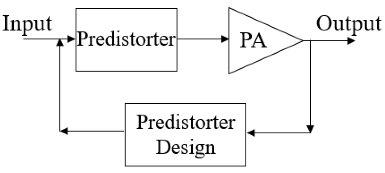
One of the most used techniques to linearize PAs is DPD. It is a cost-effective method with high linearization capability, while maintaining the overall system [33]. The rationale of using DPD techniques is to inhibit the undesired out of band emissions and passband nonlinear distortion from PAs [34]. Figure 1 illustrates a block diagram of the DPD application in wireless systems.
In the DPD operation, the main goal is to linearize the system. To achieve this, a nonlinear behavioral model is extracted to represent the nonlinear device and then the DPD function will try to equalize such model response. Then, to perform DPD, a model should be selected to operate the predistorter function, and their parameters should be identified [35]. In summary, the DPD technique is considered a digital control system, due to the fact that an observation receiver is used to feedback the PA output [36].
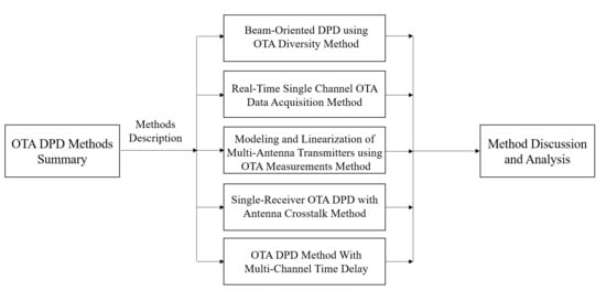
3. OTA DPD Methods Summary
Comparing with traditional DPD methods, the OTA DPD methods solve many hardware issues typically arising in conventional DPD architectures, since couplers and other types of components are removed, decreasing the hardware costs. Moreover, in methods that require dedicated feedback loop for each PA (for instance, in [37]), OTA DPD methods save hardware costs. However, to apply OTD DPD distinct process can be used.
Thus, five OTA DPD methods will be detailed in this paper, in order to demonstrate their different approaches aiming at improving the PAs operation in MIMO systems. In the first method, the beam-oriented DPD method [4], more than one OTA diversity feedbacks can be used. In the second method, real-time single channel OTA data acquisition for DPD [29], is used, with only one OTA receiver being considered, enabling the study of mutual coupling between elements. The third method is on the modeling and linearization of multi-antenna transmitters using OTA measurements [30], that uses one or more OTA receivers. The fourth method, a single-receiver OTA DPD method [31], utilizes only one receiver and the crosstalk is considered. Lastly, the fifth method [25], is focused on the linearization of phased array transmitters that present multi-channel time delay using one OTA feedback receiver.
4. Beam-Oriented DPD Using OTA Diversity
The OTA DPD method presented in [4], aims to estimate and linearize the main beam signal, avoiding the complex feedback configurations, by using diversity feedbacks. The main beam signal is derived from the OTA receiver feedback and the distortion is obtained by the main beam signal estimation. This method can be applied in hybrid MIMO architectures.
4.1. Method Description
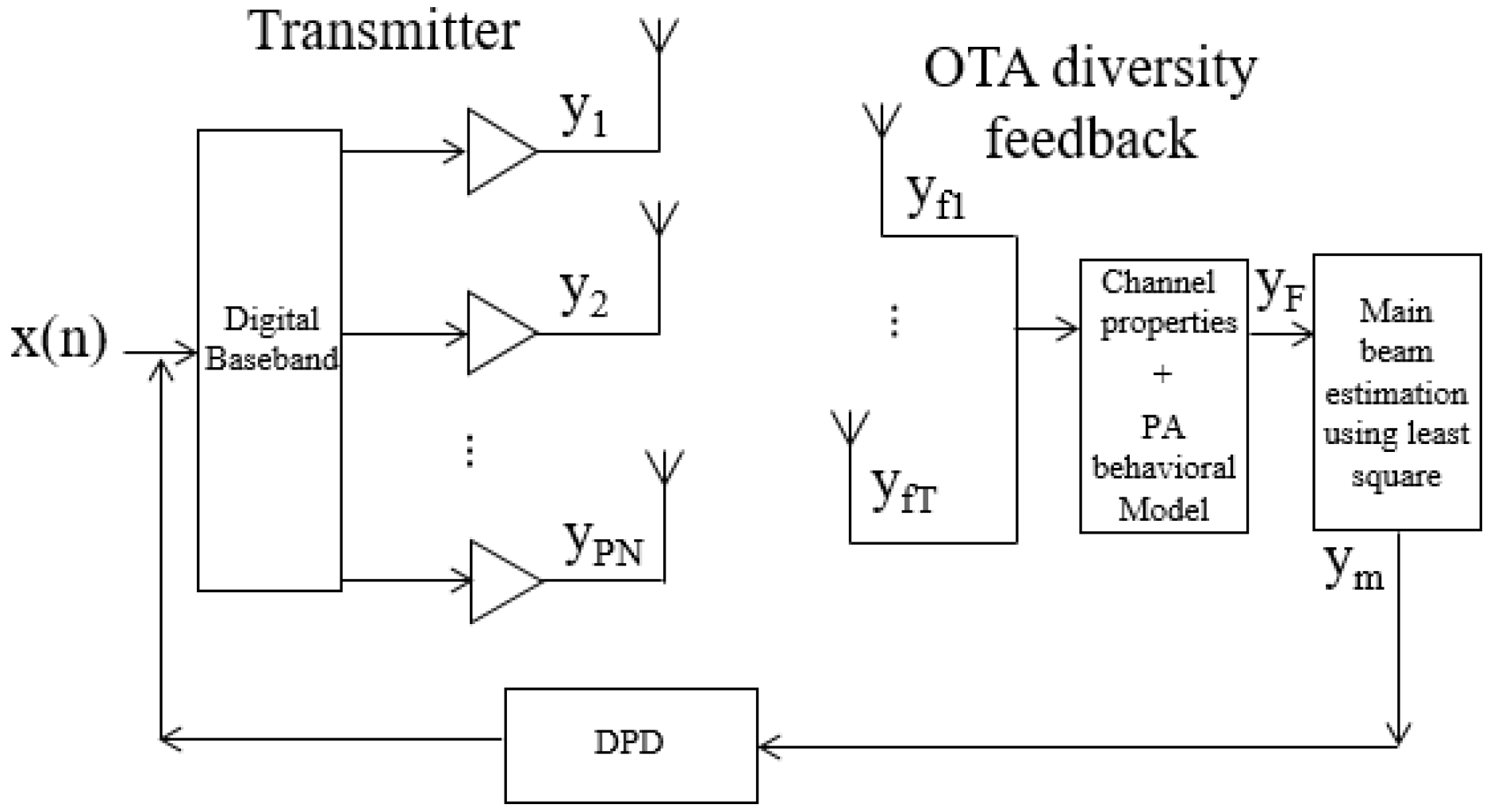
In [4], one OTA feedback antenna is used, but it may happen that the feedback signal power is lower/weak and, thus, the application of DPD is adversely affected. In this sense, this method is developed to consider, if necessary, more than one OTA feedback antenna, in order words, diversity is used. Figure 2 shows the block diagram representation of this method.
To perform the method an OTA feedback antenna (or more than one) is placed near the transmitting array antenna to obtain the channel properties. For instance, if two feedback signals are used, the total OTA feedback signal is given by:
where yf1 and yf2 are the receiver signals from the OTA antennas. It is assumed that the radio channel properties are stable (stationary), since the OTA feedback antenna is close to the transmitting array. When the feedback antenna is in the same position, the OTA feedback signal is given by:
where θF is the radio channel model at the feedback point and Y is the array output matrix, which is expressed by:
where PN is the output of each branch, as can be seen in Figure 2.
By using the PA behavioral modeling, the PA’s output can be replaced in (2) by the polynomial series of the PA’s input. Thus, replacing this in Equation (1), the OTA feedback is given by:
where Ak is the matrix composed of basic functions and the bi is the coefficients vector for the i-th PA. Moreover, F is the feedback samples. Then, the main beam signal can be written as:
where θm is the channel model for beam steering direction. By using pre-measured channel model, the estimation of the main beam signal (ym) is obtained applying the least square method by the feedback signal (yF) as:
with:
The input signal considering the i-th PA is the p-th sub-array is:
where αp is the amplitude beamforming weight for p-th sub-array and βi is the phase offset for i-th PA manage by the RF phase shifter. Then, using the input signal equation in (8), the estimated main beam signal (ym) is related to x(n), which is the original input signal, as can be seen in Figure 2.
Lastly, the predistorter to linearize the main beam signal is obtained using the indirect learning architecture, where K is the maximum nonlinearity order and J is the memory depth of the model, as presented in Equations (5) and (6):
i.e.,:
where M is the basis function matrix composed of ym, c are the predistortion coefficients and x the output of DPD.
4.2. Results and Discussion
To validate the method, a uniform linear antenna was used by the authors, but the received signal power in the OTA feedback antenna was very low, which limits the method application. Thus, two feedback antennas were used to calculate the differences in the obtained signal. In this sense, if the power of the two feedback antennas is similar, both feedback antennas are considered to calculate the main beam signal, by summing them. On the contrary, if the difference between the obtained signal in the feedback antenna one and two in terms of power is considerable, only one feedback antenna signal is used to estimate the main beam. This step is important since when using two signals with a high difference in terms of power, in which the DPD application can be degraded. The method was applied in the transmitter uniform linear array with four elements. A 64-QAM input signal with 20 MHz bandwidth was used as an input signal. The ACPR obtained without applying this OTA DPD method was −37 dBc and the ACPR obtained by applying this OTA DPD method was −49 dBc.
More than one receiver can be used in order to not degrade the DPD application, which is a benefit of this method. However, a power difference verification between OTA receivers is applied before implementing the method, to validate that two or more OTA receivers do not degrade the DPD application.
As expected with beam steering application, the beam pattern changes accordingly with the target position. Thus, the signal pattern at the OTA feedback point will change quite often. When the feedback is in a null steering position, the main beam signal is not obtained. This is a result of the main part of nonlinear components being masked by the noise floor, yielding to a rather limited or satisfactory dynamic range of the feedback signal. Therefore, the main beam reconstruction is not achievable, which is a major drawback of this method. Another disadvantage occurs when the received signal in the OTA antenna presents lower power. In this case, an additional OTA receiver is required, which increases the hardware and, consequently, the software complexities.
5. Real-Time Single Channel OTA Data Acquisition
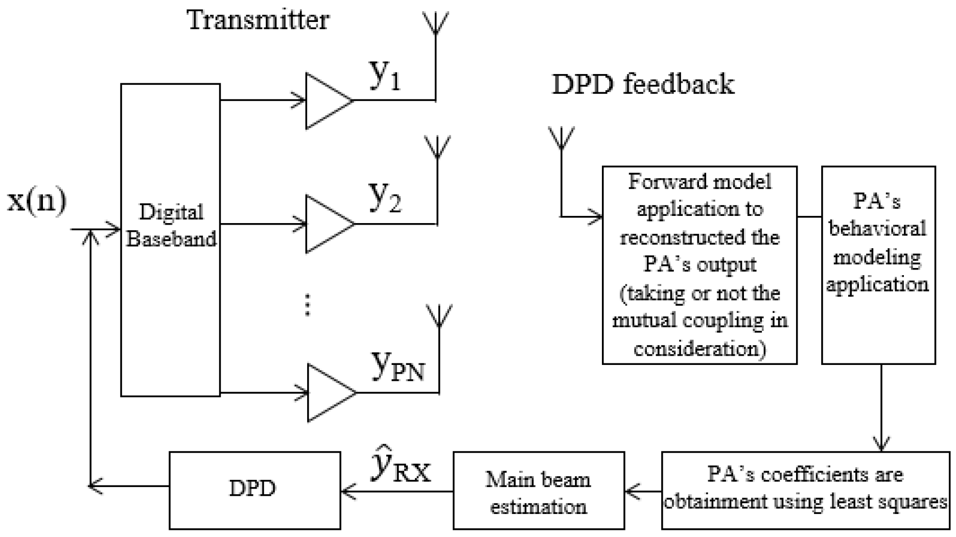
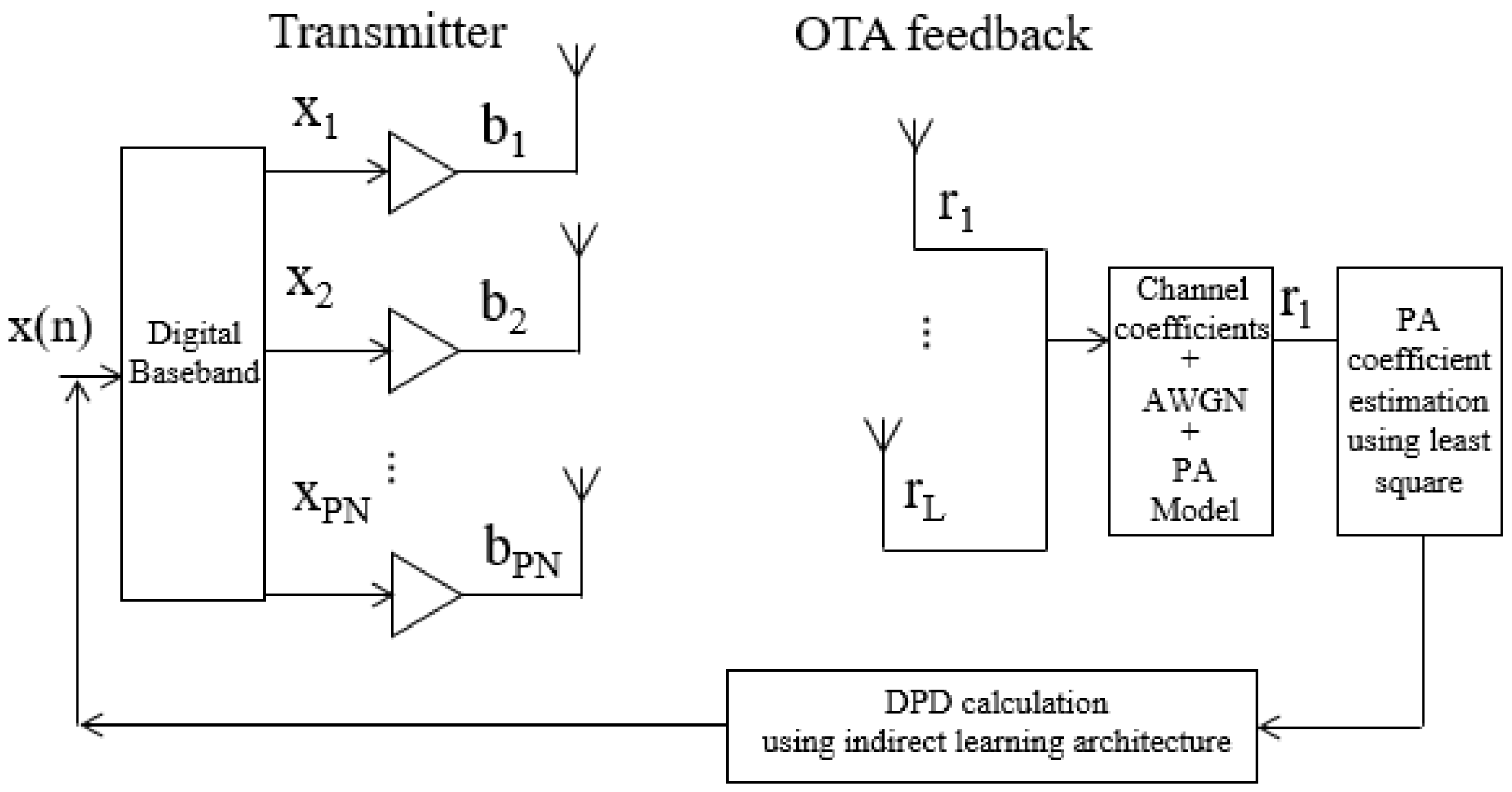
In [29], a digital predistortion architecture for MIMO transmitters using real-time single channel OTA data acquisition loop method is presented. In this method, the data is obtained from a receiving antenna in a fixed position (DPD antenna) near the transmitter antenna and the nonlinear behavior of all PAs in the array is identified. In the Far-Field (FF) distance of the antennas, the combined signal is also identified, and, consequently, the PAs’ outputs and FF main beam data are estimated. Since the user is moving, the data obtained in the DPD antenna are composed of time-phased information. This one can be used to acquire the behavioral model of PAs and to extract the DPD model coefficients. In this sense, the method is based on the assumption that FF signals are the linear combination of the transmitted signals from RF chains. Thus, this method can be applied in hybrid MIMO architectures. The same authors present a more advanced description of this method in [23], where mutual coupling between antenna elements is considered in the method application. Figure 3 illustrates the block diagram of the method presented in this section.
5.1. Method Description
To apply this method, an external DPD antenna is fixed near the transmitter antenna array to obtain data. Thus, data blocks are acquired using this DPD antenna presenting different phase combinations caused by beam steering. In this sense, the data obtained from the fixed antenna is acquired accordingly with shift variation. The channel effects are considered as phase shifts, but only in the system model.
Besides, it is considered that the RF chains are excited with the same input data, considering a single user scenario. When the system obtains several data blocks, the PA’s output is reconstructed by using forward modeling, since the signal is previously known and is transmitted accordingly with phase variations. Also, it is assumed that the nonlinear behavior of each PA is the array modeled by a PA model. Thus, the signal obtained from the DPD antenna is defined as:
where Xm is the basis functions of the model, CPApn is the PA model coefficients, assuming phase shift in phase shifter of pn-th RF chain to be (pn−1)β and corresponding phase shift in channel to be (pn−1)θ. Then, the PA coefficients are obtained using the least squares method.
Mutual coupling effects between antenna elements are critical in MIMO transmitters as they may change while the antenna main beam is steered. In this method, these effects are taking into consideration to improve performance, as presented in [23]. Thus, the mutual coupling coefficient is considered at the output of the RF chain, by using the mutual coupling matrix. Then, the forward model is applied to reconstruct the PA output. Consequently, the PA coefficients are calculated to take into account the presence of mutual coupling.
To obtain the DPD, the method is based on FF estimation and DPD coefficients. For that matter, the FF received signal is estimated based on the output of PAs and channel information. The main beam is linearized by using the estimated received signal as the linearization reference. That way, the estimated main beam signal is:
where it is assumed that X, the input matrix, is based on PA models and also considering the mutual coupling, as mentioned previously.
Finally, to obtain the DPD coefficients, the typical equation in conventional DPD is used, which is given by:
where Y is the regression matrix of post-inverse model which can be built by feeding to the DPD model. H is the complex conjugate operation of a matrix and u is the output of DPD.
CDPD = (YHY)−1 YHu
Additionally, the same authors present in [38], an upgraded version of this method to separate correlated signals in multi-user MIMO systems. In this version, the transmission is not interrupted and the data is obtained by using the multi-observation forward modeling technique and the correlated signals are separated in each RF chain. By obtaining enough data blocks, the PAs outputs are also reconstructed by using forward modeling. This occurs since distinct data with different precoding and beamforming weights prevent under-determined equations during the separation of signals which are correlated. The least squares are also used to obtain the PA model reconstruction and estimate each PA. Then, the DPD coefficients are also obtained using least squares.
5.2. Results and Discussion
To apply this method, an LTE input signal with 20 MHz bandwidth was considered. Although mutual coupling compensation was not used, the experimental results achieved an ACPR of approximately −35 dBc without using the OTA DPD method and an ACPR of approximately −54 dBc using this OTA DPD method.
In [23], when the authors considered the mutual coupling in the method and an ACPR of approximately −50 dBc for different antennas (antenna with two elements and antenna with four elements) was obtained, demonstrating robustness. An ACPR of −36 dBc was obtained without applying the OTA DPD and when the mutual coupling is considered in the method, the ACPR tends to degrade. Since it is performed in real-time the method does not interfere with MIMO transmitters and, consequently, aims to support data transmission and beam steering, which are requirements in MIMO system operation. In the presence of mutual coupling between antenna elements, the method takes this into account, presenting a robust performance.
Nevertheless, when the mutual coupling is considered in the method, the mutual coupling matrix should be known, and the software complexity of the method increase. Moreover, an additional benefit of this method to separate correlated signals in multi-user MIMO systems, which is an upgraded version of this method.
6. Modeling and Linearization of Multi-Antenna Transmitters Using OTA Measurements
Assuming that the crosstalk, caused by mutual coupling, does not introduce nonlinearities in the transmitter (or it insignificant), and that only the PA contributes with nonlinearities, the method presented in [30], aims to linearize antenna transmitters using OTA measurements. In this sense, several OTA receivers can be used, in FF, to obtain the data from the transmitting antenna. The block diagram that represents this method is described in Figure 4. The method is iterative in order to obtain the predistorter for each subarray.
6.1. Method Description
When the transmitted data is obtained from OTA receivers, the resulting signal is given by:
where ηlpn is the channel coefficient taking into account the RF branch, PN, as can be seen in Figure 4. The bpn is the transmitted signal in each branch of the transmitting antenna considering the PA output and wl represents the additive white Gaussian noise (AWGN) and l-th is the receiver input. Thus, if it is assumed that PA can be represented by a linear model in the parameters, consequently the PA is described as a summation of an arbitrary set of nonlinear basis functions. In this sense, a complex polynomial is used to model the pn-th PA:
where θpn is the complex coefficients linearly combined the set of monomials given in the nonlinear basis G(xpn(n))θpn and xpn is the PA input signal. Replacing this in (14), the obtained receiver signal is:
Applying the least squares to estimate the coefficient of all PAs, which can be written as:
where the pseudoinverse is used:
Then, the indirect learning architecture is used to obtain the predistorter for each PA.
6.2. Results and Discussion
The method was verified and validated through simulations. It was concluded that when the receiver is close to the transmitting antenna, the method achieves better results than when the receiver is at a longer distance. This occurs due to stronger coupling between receiving and transmitting antennas, creating higher channel coefficients. An OFDM input signal with 5 MHz bandwidth was considered. The experimental results achieved an ACLR of approximately −41 dB without applying this OTA DPD method and an ACLR of approximately −46 dB using this OTA DPD method.
Only one receiver is sufficient to identify all PA model coefficients. Nevertheless, using more than one receiver is important in cases where the coefficients for some RF branches are smaller. For example, when the antenna array is large, the elements which are placed in the edges of the antenna will contribute with less information for the receiver antenna (if the receiver antenna is placed in front of the transmitting antenna). This means that, in this case, using more than one receiver, the process of linearizing the system can be further improved.
Nevertheless, only simulations were considered to validate the method since real measurements were not performed. Another disadvantage is the assumption that channel coefficients are known. In terms of real-time calibration in MIMO systems, this method cannot be implemented, since required fully uncorrelated signals to be transmitted in distinct RF paths.
7. Single-Receiver OTA DPD with Antenna Crosstalk
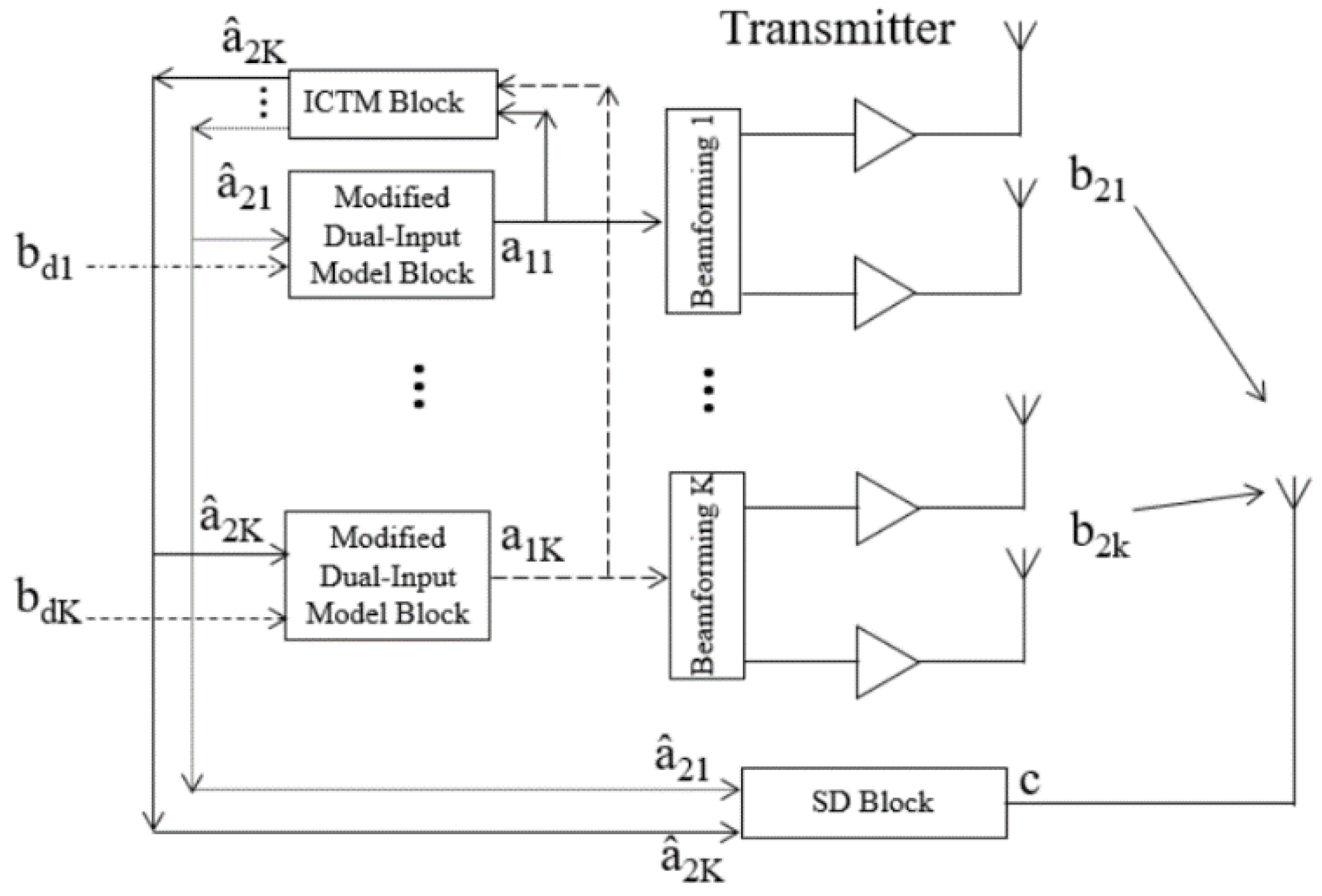
In [31] an OTA DPD technique is discussed to apply in hybrid architectures with subarrays, where antenna crosstalk is considered. In this technique, a single OTA receiver is used and several processing blocks are required. A single decomposition block is utilized to generate feedback for the predistorter of each RF path. The crosstalk signal is the predistorter input, which is a linear combination of inputs of other paths. The DPD uses an integrated linear crosstalk model. Figure 5 illustrated the block diagram of this technique.
7.1. Method Description
As previously mentioned the crosstalk is considered in this method. However, the crosstalk signal presents lower power as the input signal is known. In this sense, the PA output model considers the input signal x1PN and the crosstalk signal. To apply the method three processing blocks are used, the integrated linear crosstalk model (ICTM) block, the Signal Decomposition (SD) block and the modified dual-input model block.
The main goal of the ICTM block is to generate the crosstalk signals for every predistorter. This block operates as a forward system before the transmitter. The ICTM coefficients are estimated as a whole matrix, which is given by:
where x1 is the matrix with the input signals of analog beamforming. The term is the coefficient vectors with the final estimation of λPN and is required to be identified before DPD iterations. λpn = [λpn1, …, λpnPN] is the matrix that includes the coupling effects and general gain differences among subarrays.
The SD block decomposes the information from the OTA receiver signal into multiple signals, by using the estimated crosstalk which is provided by the ICTM block. First, the initial state of identification x1pn = bdpn is performed, where x1pn is input signals and the bdpn the original signals. Then, the received signal from OTA receiver, c, is obtained and the synchronization with one of the input paths as x1pn is performed. In a row, the received signal is decomposed and the overall coefficient vector is obtained as follows:
where R is the overall matrix containing all basic functions, bdpn is the original signals, as can be seen in Figure 5, 2pn the estimated crosstalk signals, and c the received signal from OTA receiver. Consequently, the new dual-input model, b’2pn, is reconstructed, where the receiving-end subarrays signals decomposed from c are considered, which is given by:
where θpn is the coefficient vector and G is the matrix containing the basic functions:
The next step is to normalize the b’2pn for the DPD extraction. In order to avoid that the time delay effects to affect the beamforming, the b’2pn is resynchronized with x1pn.
The main goal of the modified dual-input model block is to predistort the signal derived by each path. In this sense, the DPD coefficients are achieved by using the least squares as follows:
where x1pn is the known system inputs, 2pn is the estimated crosstalk signals provided by ICTM block and b’2pn is provided by SD block. Thereafter, the predistorter signal is given by:
The next DPD iteration can start with new inputs x1pn, in order to obtain convergence.
7.2. Results and Discussion
The method was tested with experimental results, presenting a relevant performance in presence of nonlinear antenna crosstalk. An OFDM signal with 20 MHz of bandwidth was used and the results demonstrate that for a three path transmission an ACLR around −48 dBc was achieved. This value was obtained by applying this OTA DPD method and the ACLR obtained without applying this OTA DPD method was −34 dBc.
The method takes into account the crosstalk in the MIMO transmitter, presenting lower hardware complexity. Since the method is composed of several processing blocks, taking into account the antenna crosstalk, the complexity of the method increases in terms of processing. Additionally, one of the requirements is that the original signals, bdk, are uncorrelated during the extractions of the coefficients. This increases the complexity in terms of performance.
8. OTA DPD Method with Multi-Channel Time Delay
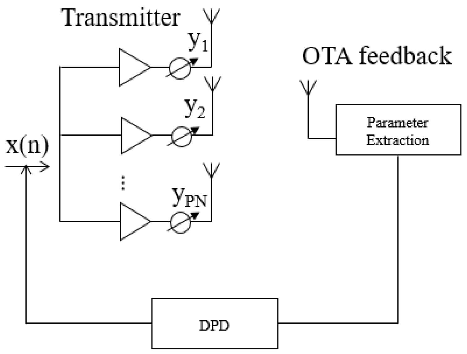
In [25] a novel OTA feedback DPD technique is presented with multi-channel time delay for phased array transmitters. In this technique, the transmitters are considered as integration, in order to considered that multi-channel time delay as a one-to-one mapping system, where only a single OTA receiver is required. The method combines the memory polynomial model, to represent the PA behavior, and the multi-channel time delay. Figure 6 illustrated the block diagram of this technique.
8.1. Method Description
As previously mentioned this method combines the memory polynomial model and multi-channel time delay, where only one OTA receiver feedback is used. In this sense, considering only one RF chain, the PA behavior is represented by:
where is the input signal, cp,i is the p-th-order of memory polynomial kernel, P is the nonlinear order and M is the memory depth. Moreover, the impulse response is able to model the multi-channel time delay involved distortion in OTA feedback loop. When the multi-channel time delay (h(τ,t)) presents a slow variation in time (t), the propagation delay (τi(t)) and the attenuation (ai(t)) do not depend on the time. Thus, the response is given by:
The baseband depiction for DPD is described as:
where:
Consequently, taking into account the sampling theorem the baseband signal is described by:
where the input signal is band limited to W and the output is sample at the rate of W. The discrete-time equivalent model, when l = m − n, is expressed by:
where:
With this in mind, since this method combines the memory polynomial model and the multi-channel time delay the output is expressed by:
Considering that k = I + l and the maximum value of l is L the resulting multi-channel memory polynomial model is given by:
where:
This means that using this equation to model one PA, by using the memory polynomial model the remaining PA in the system with multi-channel time delay are also represented with the same approach. Nevertheless, each PA is represented with another set of kernels (dp,k), which results from a convolution of the original coefficient (cp,k) and the discrete-time multi-channel impulse response (hl).
In addition, the contribution of multi-channel time delay will be mainly to hl when the time delay (τi) is among [(l − 1/2)/W, (l + 1/2)/W)]. In order to guarantee the precision of the model, the l can be limited by L = 2, because typically the time delay is lower than 1/W. In terms of maximum memory depth, the multi-channel time modeling can be truncated from M + L to M, considering the case where the memory depth M is previously defined redundantly in the conventional memory polynomial model. In this sense, the memory polynomial model can be used as the inverse model in DPD operation. After several iterations of model extraction using the indirect learning method, the final output received in the OTA feedback receiver can be obtained.
The method was applied for different time delays and for equal time delays and it was concluded that the performance with different time delays is worse than with equal time delays. This problem derives from synchronization because the synchronization processing makes the multi-channel time delay impulse responses non-negligible considering the case where the index is less than zero. To overcome this problem, in [25], a modified version of this method is presented by the same authors. In this case, the authors utilize a Volterra series based model designed with the law of causality, and the output signal is shifted by some samples after synchronization.
8.2. Results and Discussion
To validate the method an experiment with a 2-carrier OFDM signal with 20 MHz of bandwidth was used. In this experiment, the phased array transmitter with the OTA feedback was emulated and different time delay lines were employed at two channels to emulate multi-channel time delay/phase error. The experimental results achieved a normalized mean square error (NMSE) of approximately −39 dB without applying this OTA DPD method. When this OTA DPD method was applied, an NMSE of −46 dB was obtained.
Since multi-channel time delay degrades the operation of the MIMO systems, this method takes into account these effects, in order to improve the system performance, which is a benefit. Although, when typical DPD identification processing with multi-channel time delay is used the modeling error deteriorates and after some iterations, the DPD results getting worse.
However, the modified version of the method with Volterra series model solves this issue by shifting the output signal by several samples. Using the same process this updated version was only validated with simulations.
Moreover, the effect of noise was studied in this modified version of the method. If the noise floor is higher and in a scenario where the multi-channel time delay is significant, the proposed modified method expresses that this method eliminates the distortion in conventional DPD.
9. Methods Discussion
In order to have a clear view of the OTA DPD methods for the MIMO systems analyzed in this paper, a comparison between the methods is provided in Table 1. The advantages, disadvantages, ACPR/ACLR/NMSE results before and after using the OTA DPD method, the type of signal used and the number of receivers required in each method are presented.
By analyzing the methods, it can be concluded that the method presented in [31], i.e., single-receiver OTA DPD with antenna crosstalk, presents higher complexity in terms of software since several distinct blocks are required. Nevertheless, this method takes into account the antenna crosstalk, which is one of the problems that interfere with MIMO systems efficiency, which is definitely a high point on this technique.
The real-time single channel OTA data acquisition for DPD method [29], demonstrates several advantages when compared with the others. This one considers mutual coupling by using just one receiver, which decreases the hardware necessities. Furthermore, a new version of this method is able to separate correlated signals. It must be emphasized that this method has undergone several updates so that the method becomes more robust. From the first to the second version of the method, the effect of mutual coupling was added and in the third version of the method, the authors managed to separate correlated signals. This demonstrates that the authors are scaling the method to achieve a better performance, in order to reduce several effects that degrade the system.
The OTA DPD method with multi-channel time delay [25], exhibits the advantage of compensating the multi-channel time delay presented in phased array transmitters, using one OTA feedback. Although the first version of this method has the disadvantage of having worse results when the time delays are different than when they are equal. The modified version of the method compensates for this issue which is a benefit, but only simulations were used for validation and the ACPR results were not present and discussed. It should be highlighted that these three mentioned methods above use only one OTA antenna.
On the contrary, the beam-oriented DPD using OTA diversity feedbacks method [4], and the modeling and linearization of multi-antenna transmitters using OTA measurement method [30], operates with one or more OTA receivers. The latter one, [30], express a huge disadvantage comparing with the others since only simulations were used to validate the method. Although, the method [4], exhibits a low number of advantages and a huge drawback because when the OTA antenna is in a null position the system fails in terms of beam reconstruction.
It should be noted that methods that take into account mutual coupling or crosstalk ([29] and [31], respectively) and only require one OTA receiver to operate. Using fewer hardware resources (only one receiver) the methods take into account effects that degrade MIMO systems, aiming to improve their performance.
In terms of input signals to validate the methods, in method [4], a 64-QAM signal is selected. On the other hand, the other methods use more complex input signals, OFDM and LTE. Thus, the method validation with more complex input signals, makes the validation process more difficult, although it demonstrates the robustness of the method.
In summary, the software complexity, number of receivers and the performance of the methods are correlated and are essential criteria for method selection.
As mentioned previously, there are other OTA methods in the literature but with minimal variations of the ones presenting here. For instance, in [39], the same method described in [4], is presented, however with structural improvements of the OTA setups. In this case, an iterative procedure and algorithm were applied to eradicate in the OTA receiver the uncorrelated components. Furthermore, the method [30], is used in [40], with some changes to cascade DPD with the digital beamforming network in order to solve beam issues in the multi-user scenario. Besides, in [40], the authors considered a vector rotation-based model to reach the modeling accuracy and experimental results were obtained, not only simulations.
10. Conclusions
This paper presents a critical review of the most distinct OTA DPD methods for the MIMO systems present in literature, particularly for 5G. Each method was analyzed in order to give a clear view of this research topic, demonstrating the advantages and disadvantages of each method. Besides, a comparison and discussion of the methods were performed. An overall review of the methods in order to select the best method for a specific purpose is presented, contributing to the state of the art in this research topic.
Author Contributions
Conceptualization, M.J. and N.B.C.; methodology, M.J., R.C., A.S.R.O. and N.B.C.; investigation, M.J.; writing—original draft preparation, M.J.; writing—review and editing, M.J., R.C., A.S.R.O. and N.B.C.; validation, M.J., R.C., A.S.R.O. and N.B.C.; visualization, M.J., R.C., A.S.R.O. and N.B.C.; supervision, N.B.C.; funding acquisition, N.B.C. All authors have read and agreed to the published version of the manuscript.
Funding
The work of M.J. was supported by the Fundação para a Ciência e Tecnologia (F.C.T.) through Fundo Social Europeu (FSE), UE and by Programa Operacional Regional do Centro under Ph.D. Grant SFRH/BD/143204/2019. This work was sponsored in part by the Roger Pollard Student Fellowship from the Automatic RF Techniques Group. This work is funded by FCT/MCTES through national funds and when applicable co-funded EU funds under the project UIDB/50008/2020-UIDP/50008/2020.
Institutional Review Board Statement
Not applicable.
Informed Consent Statement
Not applicable.
Conflicts of Interest
The authors declare no conflict of interest.
References
- Larsson, E.G.; Edfors, O.; Tufvesson, F.; Marzetta, T.L. Massive MIMO for Next Generation Wireless Systems. IEEE Commun. Mag. 2014, 52, 186–195. [Google Scholar] [CrossRef] [Green Version]
- Boccardi, F.; Heath, R.W.; Lozano, A.; Marzetta, T.L.; Popovski, P. Five Disruptive Technology Directions for 5G. IEEE Commun. Mag. 2014, 52, 74–80. [Google Scholar] [CrossRef] [Green Version]
- Salman, M.B.; Guvensen, G.M. On the Effects of PA Nonlinearities for Hybrid Beamforming Based Wideband Massive MIMO Systems. In Proceedings of the ICC 2020–2020 IEEE International Conference on Communications (ICC), Dublin, Ireland, 7–11 June 2020; pp. 1–7. [Google Scholar]
- Liu, X.; Chen, W.; Chen, L.; Feng, Z. Beam-Oriented Digital Predistortion for Hybrid Beamforming Array Utilizing Over-the-Air Diversity Feedbacks. In Proceedings of the IEEE MTT-S International Microwave Symposium (IMS) 2019, Boston, MA, USA, 2–7 June 2019; pp. 987–990. [Google Scholar]
- Molisch, A.F.; Ratnam, V.V.; Han, S.; Li, Z.; Nguyen, S.L.H.; Li, L.; Haneda, K. Hybrid Beamforming for Massive MIMO: A Survey. IEEE Commun. Mag. 2017, 55, 134–141. [Google Scholar] [CrossRef] [Green Version]
- Jalili, F.; Nielsen, M.H.; Shen, M.; Jensen, O.K.; Mikkelsen, J.H.; Pedersen, G.F. Linearization of Active Transmitter Arrays in Presence of Antenna Crosstalk for 5G Systems. In Proceedings of the 2019 IEEE Nordic Circuits and Systems Conference (NORCAS): NORCHIP and International Symposium of System-on-Chip (SoC), Helsinki, Finland, 29–30 October 2019; pp. 1–5. [Google Scholar]
- Tervo, N.; Jokinen, M.; Leinonen, M.E.; Aikio, J.; Kursu, O.; Rahkonen, T.; Parssinen, A. Digital Predistortion Concepts for Linearization of mmW Phased Array Transmitters. In Proceedings of the 2019 16th International Symposium on Wireless Communication Systems (ISWCS), Oulu, Finland, 27–30 August 2019; pp. 325–329. [Google Scholar]
- Tervo, N.; Khan, B.; Kursu, O.; Aikio, J.P.; Jokinen, M.; Leinonen, M.E.; Juntti, M.; Rahkonen, T.; Parssinen, A. Digital Predistortion of Phased-Array Transmitter with Shared Feedback and Far-Field Calibration. IEEE Trans. Microw. Theory Tech. 2021, 69, 1000–1015. [Google Scholar] [CrossRef]
- Bjornson, E.; Hoydis, J.; Kountouris, M.; Debbah, M. Massive MIMO Systems With Non-Ideal Hardware: Energy Efficiency, Estimation, and Capacity Limits. IEEE Trans. Inf. Theory 2014, 60, 7112–7139. [Google Scholar] [CrossRef] [Green Version]
- Mollén, C.; Gustavsson, U.; Eriksson, T.; Larsson, E.G. Out-of-band Radiation Measure for MIMO Arrays with Beamformed Transmission. In Proceedings of the 2016 IEEE International Conference on Communications (ICC) 2016, Kuala Lumpur, Malaysia, 23–27 May 2016; pp. 1–6. [Google Scholar]
- Shen, J.; Suyama, S.; Obara, T.; Okumura, Y. Requirements of Power Amplifier on Super High Bit Rate Massive MIMO OFDM Transmission Using Higher Frequency Bands. In Proceedings of the 2014 IEEE Globecom Workshops (GC Wkshps), Austin, TX, USA, 8–12 December 2014; pp. 433–437. [Google Scholar]
- Zou, Y.; Raeesi, O.; Antilla, L.; Hakkarainen, A.; Vieira, J.; Tufvesson, F.; Cui, Q.; Valkama, M. Impact of Power Amplifier Nonlinearities in Multi-User Massive MIMO Downlink. In Proceedings of the 2015 IEEE Globecom Workshops (GC Wkshps), San Diego, CA, USA, 6–10 December 2015; pp. 1–7. [Google Scholar]
- Gustavsson, U.; Sanchez-Perez, C.; Eriksson, T.; Athley, F.; Durisi, G.; Landin, P.; Hausmair, K.; Fager, C.; Svensson, L. On the Impact of Hardware Impairments on Massive MIMO. In Proceedings of the 2014 IEEE Globecom Workshops (GC Wkshps), Austin, TX, USA, 8–12 December 2014; pp. 294–300. [Google Scholar]
- Prabhu, H.; Rodrigues, J.; Liu, L.; Edfors, O. Algorithm and Hardware Aspects of Pre-coding in Massive MIMO Systems. In Proceedings of the 2015 49th Asilomar Conference on Signals, Systems and Computers, Pacific Grove, CA, USA, 8–11 November 2015; pp. 1144–1148. [Google Scholar]
- Mollen, C.; Larsson, E.; Gustavsson, U.; Eriksson, T.; Heath, R. Outof-band Radiation from Large Antenna Arrays. IEEE Commun. Mag. 2018, 56, 196–203. [Google Scholar] [CrossRef] [Green Version]
- Guan, L.; Zhu, A. Green Communications: Digital Predistortion for Wideband RF Power Amplifiers. IEEE Microw. Mag. 2014, 15, 84–99. [Google Scholar] [CrossRef] [Green Version]
- Ghannouchi, F.M.; Hammi, O.; Helaoui, M. Behavioral Modeling and Predistortion. IEEE Microw. Mag. 2015, 10, 52–64. [Google Scholar] [CrossRef]
- Brihuega, A.; Abdelaziz, M.; Anttila, L.; Turunen, M.; Allen, M.; Eriksson, T.; Valkama, M. Piecewise Digital Predistortion for mmWave Active Antenna Arrays: Algorithms and Measurements. IEEE Trans. Microw. Theory Tech. 2020, 68, 4000–4017. [Google Scholar] [CrossRef]
- Liu, L.; Chen, W.; Ma, L.; Sun, H. Single-PA-feedback Digital Predistortion for Beamforming MIMO Transmitter. In Proceedings of the 2016 IEEE International Conference on Microwave and Millimeter Wave Technology (ICMMT), Beijing, China, 5–8 June 2016. [Google Scholar] [CrossRef]
- Huang, H.; Xia, J.; Boumaiza, S. Novel Parallel-Processing-Based Hardware Implementation of Baseband Digital Predistorters for Linearizing Wideband 5G Transmitters. IEEE Trans. Microw. Theory Tech. 2020, 68, 4066–4076. [Google Scholar] [CrossRef]
- Lee, S.; Kim, M.; Sirl, Y.; Jeong, E.-R.; Hong, S.; Kim, S.; Lee, Y.H. Digital Predistortion for Power Amplifiers in Hybrid MIMO Systems with Antenna Subarrays. In Proceedings of the 2015 IEEE 81st Vehicular Technology Conference (VTC Spring), Glasgow, UK, 11–14 May 2015; pp. 1–5. [Google Scholar]
- Abdelaziz, M.; Anttila, L.; Brihuega, A.; Tufvesson, F.; Valkama, M. Digital Predistortion for Hybrid MIMO Transmitters. IEEE J. Sel. Top. Signal Process. 2018, 12, 445–454. [Google Scholar] [CrossRef] [Green Version]
- Wang, X.; Li, Y.; Yu, C.; Hong, W.; Zhu, A. Digital Predistortion of 5G Massive MIMO Wireless Transmitters Based on Indirect Identification of Power Amplifier Behavior With OTA Tests. IEEE Trans. Microw. Theory Tech. 2019, 68, 316–328. [Google Scholar] [CrossRef]
- Luo, Q.; Yu, C.; Zhu, X.-W. Digital predistortion of phased array transmitters with multi-channel time delay. In Proceedings of the 2018 IEEE Topical Conference on RF/Microwave Power Amplifiers for Radio and Wireless Applications (PAWR), Anaheim, CA, USA, 14–17 January 2018; pp. 54–57. [Google Scholar]
- Luo, Q.; Yu, C.; Zhu, X.-W. A Modified Digital Predistortion Method for Phased Array Transmitters with Multi-Channel Time Delay. In Proceedings of the 2018 IEEE MTT-S International Microwave Workshop Series on 5G Hardware and System Technologies (IMWS-5G), Dublin, Ireland, 30–31 August 2018; pp. 1–3. [Google Scholar]
- Ng, E.; Beltagy, Y.; Mitran, P.; Boumaiza, S. Single-Input Single-Output Digital Predistortion of Power Amplifier Arrays in Millimeter Wave RF Beamforming Transmitters. In Proceedings of the 2018 IEEE/MTT-S International Microwave Symposium–IMS, Philadelphia, PA, USA, 10–15 June 2018; pp. 481–484. [Google Scholar]
- Wood, J. System-Level Design Considerations for Digital Pre-Distortion of Wireless Base Station Transmitters. IEEE Trans. Microw. Theory Tech. 2017, 65, 1880–1890. [Google Scholar] [CrossRef]
- Jalili, F.; Tafuri, F.F.; Jensen, O.K.; Li, Y.; Shen, M.; Pedersen, G.F. Linearization Trade-Offs in a 5G mmWave Active Phased Array OTA Setup. IEEE Access 2020, 8, 110669–110677. [Google Scholar] [CrossRef]
- Wang, X.; Yu, C.; Li, Y.; Hong, W.; Zhu, A. Real-Time Single Channel Over-the-Air Data Acquisition for Digital Predistortion of 5G Massive MIMO Wireless Transmitters. In Proceedings of the 2019 IEEE MTT-S International Wireless Symposium (IWS), Guangzhou, China, 19–22 May 2019; pp. 1–3. [Google Scholar]
- Hausmair, K.; Gustavsson, U.; Fager, C.; Eriksson, T. Modeling and Linearization of Multi-Antenna Transmitters Using Over-the-Air Measurements. In Proceedings of the 2018 IEEE International Symposium on Circuits and Systems (ISCAS), Florence, Italy, 27–30 May 2018; pp. 1–4. [Google Scholar]
- Luo, Q.; Zhu, X.-W.; Yu, C.; Hong, W. Single-Receiver Over-the-Air Digital Predistortion for Massive MIMO Transmitters with Antenna Crosstalk. IEEE Trans. Microw. Theory Tech. 2019, 68, 301–315. [Google Scholar] [CrossRef]
- Ahmad, I.; Sulyman, A.I.; Alsanie, A.; Alasmari, A. On the Effect of Amplifier Non-linearity on the Capacity of MIMO Systems. In Proceedings of the 2011 IEEE GCC Conference and Exhibition (GCC), Dubai, UAE, 19–22 February 2011; pp. 108–111. [Google Scholar]
- Ferguson, S.; Chopra, A. Real-time Digital Predistortion for Radio Frequency Power Amplifier Linearization. In Proceedings of the 2016 IEEE MTT-S International Wireless Symposium (IWS), Shanghai, China, 14–16 March 2016; pp. 1–4. [Google Scholar]
- Campo, P.P.; Lampu, V.; Anttila, L.; Brihuega, A.; Allen, M.; Guo, Y.; Valkama, M. Closed-Loop Sign Algorithms for Low-Complexity Digital Predistortion: Methods and Performance. IEEE Trans. Microw. Theory Tech. 2021, 69, 1048–1062. [Google Scholar] [CrossRef]
- Hussein, M.A.; Venard, O.; Feuvrie, B.; Wang, Y. Digital Predistortion for RF Power Amplifiers: State of the Art and Advanced Approaches. In Proceedings of the 2013 IEEE 11th International New Circuits and Systems Conference (NEWCAS), Paris, France, 16–19 June 2013; pp. 1–4. [Google Scholar]
- Wood, J. Digital Pre-distortion of RF Power Amplifiers. In Proceedings of the 2017 IEEE Topical Conference on RF/Microwave Power Amplifiers for Radio and Wireless Applications (PAWR), Phoenix, AZ, USA, 15–18 January 2017; pp. 1–3. [Google Scholar]
- Liu, X.; Zhang, Q.; Chen, W.; Feng, H.; Chen, L.; Ghannouchi, F.M.; Feng, Z. Beam-Oriented Digital Predistortion for 5G Massive MIMO Hybrid Beamforming Transmitters. IEEE Trans. Microw. Theory Tech. 2018, 66, 3419–3432. [Google Scholar] [CrossRef]
- Wang, X.; Li, Y.; Yu, C.; Hong, W.; Zhu, A. OTA-Based Data Acquisition and Signal Separation for Digital Predistortion of Multi-User MIMO Transmitters in 5G. In Proceedings of the 2020 IEEE/MTT-S International Microwave Symposium (IMS), Los Angeles, CA, USA, 21–26 June 2020; pp. 845–848. [Google Scholar]
- Liu, X.; Chen, W.; Chen, L.; Ghannouchi, F.M.; Feng, Z. Linearization for Hybrid Beamforming Array Utilizing Embedded Over-the-Air Diversity Feedbacks. IEEE Trans. Microw. Theory Tech. 2019, 67, 5235–5248. [Google Scholar] [CrossRef]
- Jing, J.; Shao, H.; Yan, P.; Jiang, Z.H.; Yu, C. Digital Predistortion of Millimeter-Wave Multi-beam Transmitters with Digital Beam-forming Network. In Proceedings of the 2019 IEEE MTT-S International Wireless Symposium (IWS), Guangzhou, China, 19–22 May 2019; pp. 1–3. [Google Scholar]
Figure 1.
Block diagram of a DPD representation followed by a PA.

Figure 2.
Block diagram representing the steps to apply the beam-oriented DPD using OTA diversity feedback method.
Figure 2.
Block diagram representing the steps to apply the beam-oriented DPD using OTA diversity feedback method.

Figure 3.
Block diagram representing the steps to apply the beam-oriented DPD using OTA diversity feedback method.
Figure 3.
Block diagram representing the steps to apply the beam-oriented DPD using OTA diversity feedback method.

Figure 4.
Block diagram representing the steps to apply the modeling and linearization of multi-antenna transmitters using OTA measurements method.
Figure 4.
Block diagram representing the steps to apply the modeling and linearization of multi-antenna transmitters using OTA measurements method.

Figure 5.
Block diagram representing the steps to apply the single-receiver OTA DPD with antenna crosstalk using OTA measurements method.
Figure 5.
Block diagram representing the steps to apply the single-receiver OTA DPD with antenna crosstalk using OTA measurements method.

Figure 6.
Block diagram representing the steps to apply the single-receiver OTA DPD with antenna crosstalk using OTA measurements method.
Figure 6.
Block diagram representing the steps to apply the single-receiver OTA DPD with antenna crosstalk using OTA measurements method.


Table 1.
OTA DPD methods for MIMO systems comparison.
| Methods | Advantages | Disadvantages | ACPR/ACLR and NMSE Results | Type of Signal | Number of Receivers |
|---|---|---|---|---|---|
| Beam-oriented DPD using OTA diversity feedbacks [4] |
|
| ACPR
| 64 QAM modulation with 20 MHz bandwidth | One or more receivers can be used. |
| Real-time single channel OTA data acquisition for DPD method [29] |
|
| ACPR
| LTE with 20 MHz bandwidth | One receiver is used. |
| Modeling and linearization of multi-antenna transmitters using OTA measurements [30] |
|
| ACLR
| OFDM with 5 MHz bandwidth | One or more receivers can be used. |
| Single-receiver OTA DPD with antenna crosstalk [31] |
|
| ACLR
| OFDM with 20 MHz bandwidth | One receiver is used. |
| OTA DPD method with multi-channel time delay [25] |
|
| NMSE
| OFDM with 20 MHz bandwidth | One receiver is used. |
Publisher’s Note: MDPI stays neutral with regard to jurisdictional claims in published maps and institutional affiliations. |
© 2021 by the authors. Licensee MDPI, Basel, Switzerland. This article is an open access article distributed under the terms and conditions of the Creative Commons Attribution (CC BY) license (https://creativecommons.org/licenses/by/4.0/).
Share and Cite
MDPI and ACS Style
Jordão, M.; Caldeirinha, R.; Oliveira, A.S.R.; Carvalho, N.B. A Survey on Over-The-Air Linearization Methods for MIMO Systems. Energies 2021, 14, 2225. https://0-doi-org.brum.beds.ac.uk/10.3390/en14082225
AMA Style
Jordão M, Caldeirinha R, Oliveira ASR, Carvalho NB. A Survey on Over-The-Air Linearization Methods for MIMO Systems. Energies. 2021; 14(8):2225. https://0-doi-org.brum.beds.ac.uk/10.3390/en14082225
Chicago/Turabian StyleJordão, Marina, Rafael Caldeirinha, Arnaldo S. R. Oliveira, and Nuno Borges Carvalho. 2021. "A Survey on Over-The-Air Linearization Methods for MIMO Systems" Energies 14, no. 8: 2225. https://0-doi-org.brum.beds.ac.uk/10.3390/en14082225
Note that from the first issue of 2016, this journal uses article numbers instead of page numbers. See further details here.