
Structural Design Optimization of Micro-Thermoelectric Generator for Wearable Biomedical Devices


Micro-Nano Systems Centre, Tyndall National Institute, University College Cork, Dyke Parade, Lee Maltings, T12 R5CP Cork, Ireland
*
Author to whom correspondence should be addressed.
†
These authors contributed equally.
Energies 2021, 14(8), 2339; https://0-doi-org.brum.beds.ac.uk/10.3390/en14082339
Submission received: 25 March 2021
/
Revised: 15 April 2021
/
Accepted: 16 April 2021
/
Published: 20 April 2021
(This article belongs to the Topic Thermoelectric Energy Harvesting)
Abstract
:Wearable sensors to monitor vital health are becoming increasingly popular both in our daily lives and in medical diagnostics. The human body being a huge source of thermal energy makes it interesting to harvest this energy to power such wearables. Thermoelectric devices are capable of converting the abundantly available body heat into useful electrical energy using the Seebeck effect. However, high thermal resistance between the skin and the device leads to low-temperature gradients (2–10 K), making it difficult to generate useful power by this device. This study focuses on the design optimization of the micro-thermoelectric generator for such low-temperature applications and investigates the role of structural geometries in enhancing the overall power output. Electroplated p-type bismuth antimony telluride (BiSbTe) and n-type copper telluride (CuTe) materials’ properties are used in this study. All the simulations and design optimizations were completed following microfabrication constraints along with realistic temperature gradient scenarios. A series of structural optimizations were performed including the thermoelectric pillar geometries, interconnect contact material layers and fill factor of the overall device. The optimized structural design of the micro-thermoelectric device footprint of 4.5 × 3.5 mm2, with 240 thermoelectric leg pairs, showcased a maximum power output of 0.796 mW and 3.18 mW when subjected to the low-temperature gradient of 5 K and 10 K, respectively. These output power values have high potential to pave the way of realizing future wearable devices.
1. Introduction
Monitoring health has always been paramount for humanity. The current demand on the wearable health electronics showcases the growing interest and need for portable and energy-efficient biomedical devices that have a range of sensors [1,2]. Chemical batteries are the most common power source for these wearable sensors and devices. With a limited amount of stored energy, the battery needs to be replenished every time after draining the energy, which usually involves detaching the device from the body [3]. A lot of research has been reported on improving the energy densities of the batteries [4,5,6,7].
However, despite these advances, batteries are hardly able to meet the present requirements, especially for applications requiring continuous operation and reliability in wearable sensors. The human body is a powerhouse, where the body continuously emits heat energy generated through metabolic functions into the ambient atmosphere and only varies depending on physical activity [8,9,10,11].
This ever-present thermal energy of the body can be converted into useful electricity using the thermoelectric generator (TEG) and act as a power source for the wearable devices without a battery. Thermoelectric devices are solid-state device that convert heat into electricity. When a TEG is attached to the human body, the body heat flows through the TEG to the ambient atmosphere, creating a temperature gradient across the device. Depending on the Seebeck effect of the constituent materials (p- and n-type thermoelectric materials) of the device, power is generated proportional to the temperature gradient [12,13].
The TEG for human body applications adapted previously are either large and rigid TEG’s or the recently developed macro-sized flexible TEGs [14,15,16,17]. The rigid TEGs suffer from making proper thermal contact because of the curved structure of human body, leading to higher thermal resistance and degraded TEG performance. The rigid and bulky nature of these macro-devices makes them impractical for wearable application. On the other hand, flexible TEGs can be conformally wrapped on the body, which lowers the thermal resistance, but they still suffer to achieve high power outputs because of the lack of high-efficiency flexible thermoelectric materials [18]. Micro-TEGs can play a major role in these kinds of applications, because of their small dimension, low weight, high integration and low thermoelectric material usage [19,20,21,22,23,24,25,26,27,28,29]. The small footprint and light weight of these micro-devices makes them insusceptible to body contours and allow them to establish intimate thermal contact with minimal thermal resistance.
The performance and efficiency of a thermoelectric device mainly depends on two aspects: namely, the thermoelectric material efficiency and the design optimization of the device. The efficiency of thermoelectric materials is determined by the figure of merit, ZT = α2σT/κ, where α is the Seebeck coefficient, σ is the electrical conductivity, T is the absolute temperature and κ is the thermal conductivity of the material. For a material to have a better ZT, it is required to have high electrical conductivity along with a high Seebeck coefficient and low thermal conductivity [12]. The other aspect of the device performance is the device design, which also plays a significant role in extracting the maximum possible power for a given scenario. This design is associated with various design parameters of the device to enhance the power output as well as the efficiency of the energy conversion.
Geometrical parameters’ impact on the device performance on macro- and micro-thermoelectric devices have been investigated and reported in the literature [30,31,32,33]. However, the impact of various vital structural aspects of the device design using realistic material properties, and the keeping fabrication constraints of the device to enhance the device performance, are still missing. The majority of the work has been carried out in optimizing the various features for macro-devices. Particularly, the design optimization of the micro-thermoelectric devices for power generation applications for the low-temperature gradient scenario has not been explored.
This paper investigates the design optimization of the micro-thermoelectric device for power generation and efficiency from a single-leg pair to a complete device. The primary focus is on the geometrical optimization, which was analyzed by varying different design parameters. In this endeavor, all the simulations were carried out using real materials’ properties near room temperature and developed by electrodeposition techniques and are reported in our previous works [34,35]. Electrodeposited p-type BiSbTe and n-type CuTe materials were used for the device performance evaluation with gold as the interconnect material. The five main parameters including the shape, height, interconnect material thickness, choice of filler material and the cross-sectional area of the single-leg pair were optimized and are discussed in detail. On the basis of the simulation results of the single-leg pair, a complete micro-TEG was designed and evaluated for human wearable applications. Our modeling and simulation results should provide a thorough understanding of the design of the micro-TEG with the smallest footprint, which could be an ideal power source for on-body applications, specifically for low-temperature gradient scenarios, which have not been discussed much in the literature.
2. Simulation Approach
The impact of leg geometry and structure were analyzed and optimized for the highest electrical power output and efficiency of the micro-thermoelectric generator by the finite element method (FEM) using COMSOL Multiphysics.
The thermoelectric effect results from three primary effects: the Seebeck effect, the Peltier effect and the Thomson effect. The three-dimensional governing equations that relate the thermal and electrical current density along with the three basic thermoelectric effects are given by [36]:
where ĸ is the thermal conductivity, σ is the electrical conductivity, α is the Seebeck coefficient of the thermoelectric materials and T is the absolute temperature. The current density vector (J) and heat flux vector (q) for the TEG module in three dimensions can be calculated using Equations 3 and 4, where V is the electrostatic potential:
∇. J = 0
J = −σ (∇ V + α∇ T)
q = αT J − ĸ∇ T
When a temperature gradient between the hot and cold side of the TEG module exists, the output power of the TEG is [37]:
where and are the hot and cold surface temperature of the TEG, respectively, is the relative Seebeck coefficient of the p-type and n-type semiconductors ( and and are the internal resistance of the TEG and load resistance, respectively.
The total internal resistance of the TEG is given as:
where is the resistance of the p-type semiconductor, is the resistance of the n-type semiconductor, is the interconnect (gold) resistance and is the contact resistance between the gold interconnect and thermoelectric legs. When the load resistance is equal to the internal resistance of the TEG, the maximum output power is attained and given by the equation below:
The thermoelectric materials used in modeling were electrochemically deposited CuTe (n-type) and BiSbTe (p-type). The top and bottom contact materials were chosen as Au, and the substrate was selected as Si/SiO2. The thermoelectric materials properties used in the simulation are shown in Table 1.
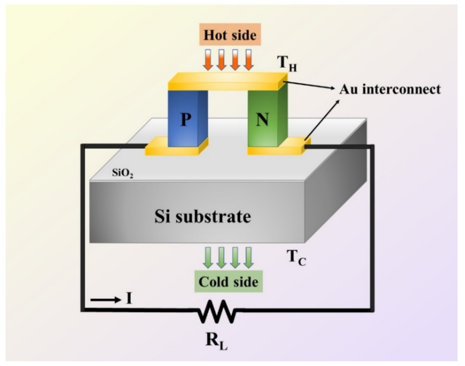
To create a temperature gradient of 5 K, the upper surface of the top interconnect material was fixed at 305 K, while the bottom substrate temperature was fixed at 300 K. Except for the top and the bottom surfaces of the device, the rest of the surfaces were assumed to be thermally isolated. Thermal resistance between the TEG and heat source was not taken into consideration for the simplicity of the design. Electrical resistance between the thermoelectric legs and interconnecting materials for both the top and bottom interfaces was taken as = 1 × 10⁻¹¹ Ωm2 [38]. The TEG module’s schematic diagram composed of one TE leg pair with an external load is shown in Figure 1.
3. Results and Discussions
3.1. Shape of the Pillars
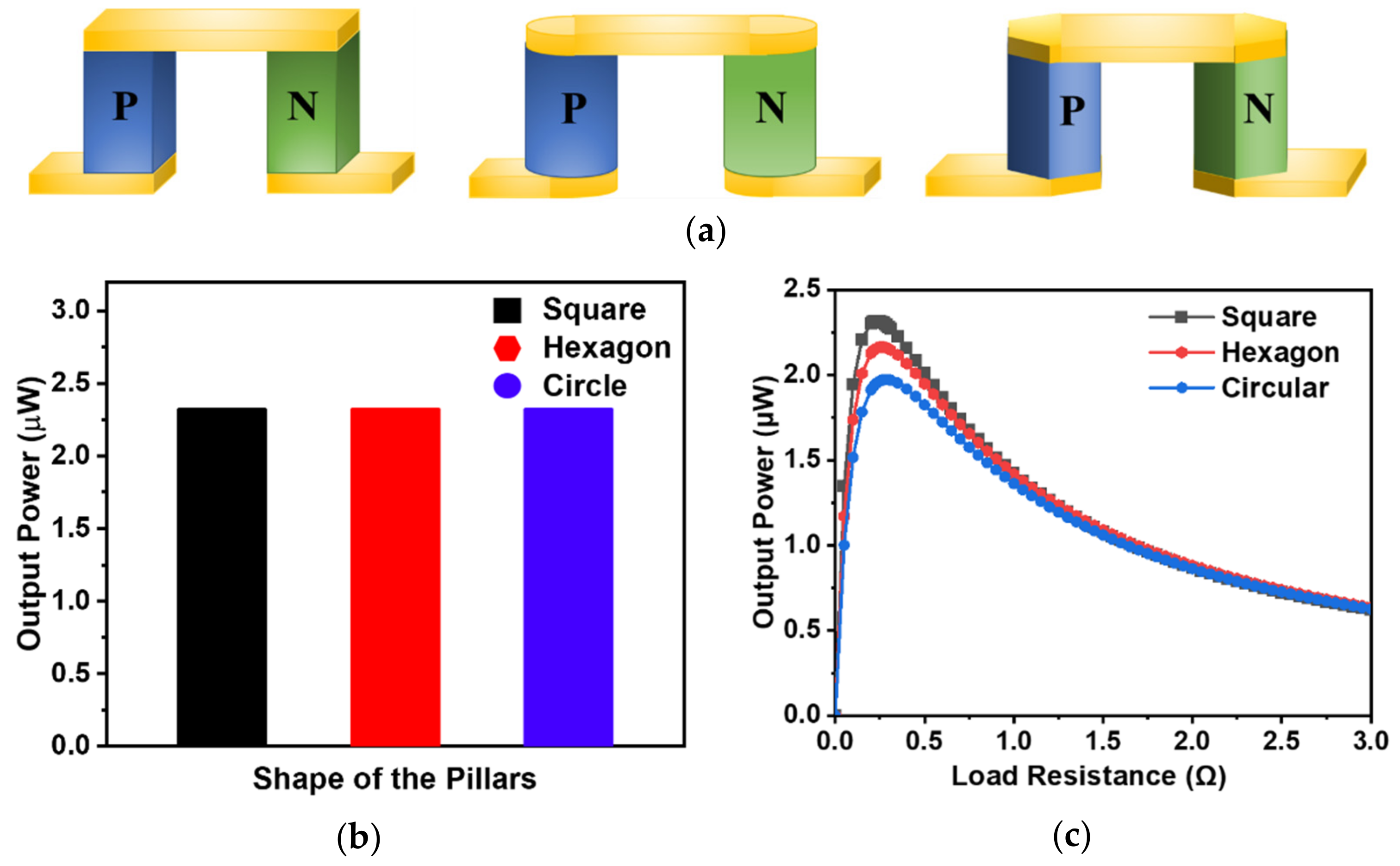
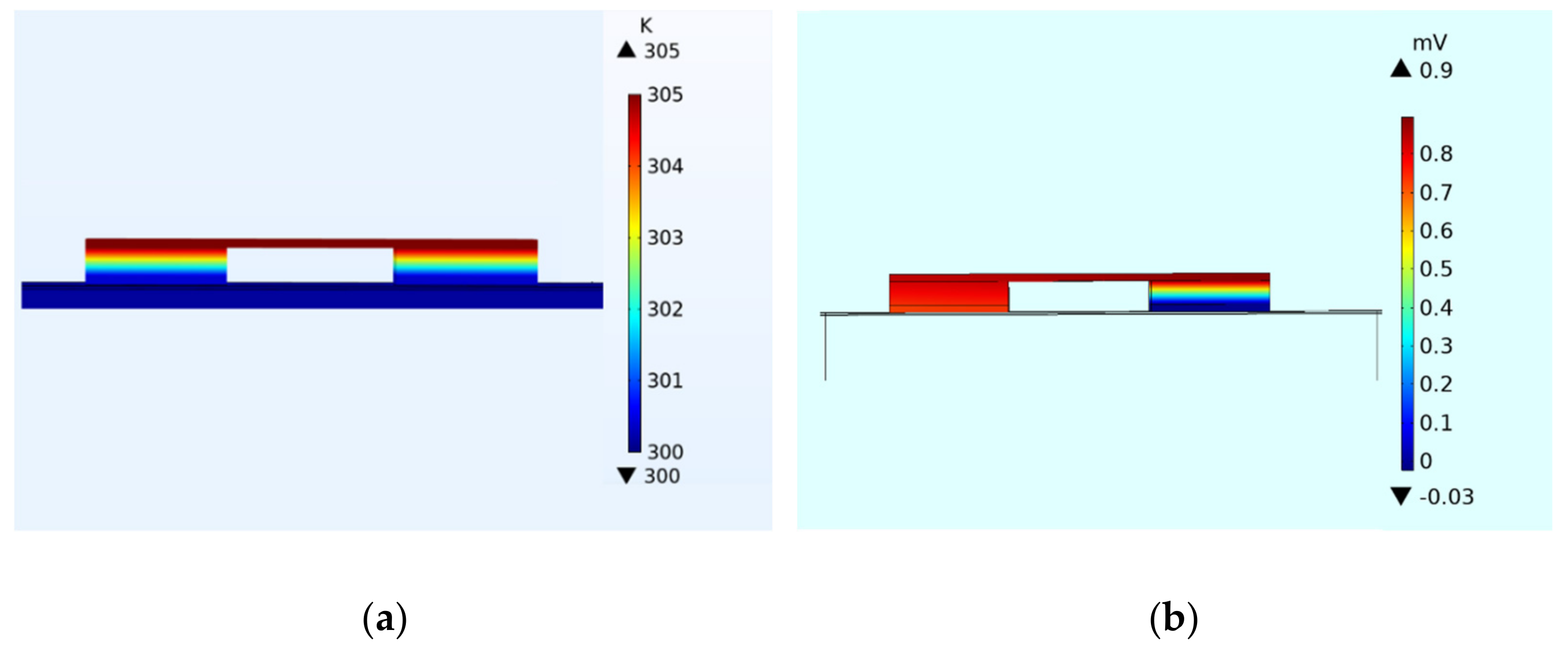
The shape of the pillars plays a vital role in device performance and in reducing the complexity of microfabrication. Square, rectangle, circular and trapezoidal pillar shapes have been fabricated with a different footprint area of the pillars and reported [32,33]. However, three different types of pillar shapes, namely, square, hexagonal and circular, were studied/simulated to optimize the device output power, as shown in Figure 2a. Keeping the cross-sectional area of the pillars constant does not have any influence on the output power obtained for the device when subjected to a constant temperature gradient because of the equal electrical resistance of each leg pair, as shown in Figure 2b. However, for a fixed effective area of a device, the equal cross-sectional area for different shapes has a considerable significance on the number of pillars that can be accommodated in that device. In order to evaluate the effect of the pillar shape on the device with the equal number of TEG leg pairs, the cross-sectional areas of the different shapes were adjusted accordingly. The power output of a single-TEG leg pair with different shapes was evaluated when subjected to a temperature gradient of 5 K, and the obtained corresponding power outputs for varied load resistance are shown in Figure 2c. The maximum output power of the individual leg pair with a different shape of the cross-section was achieved when the corresponding internal resistance of the leg pairs was equated to the load resistance applied (=). Figure 2c shows that the maximum output power achieved by the square-shaped pillar was 2.32 mW, which was 18.37% and 7.41% higher compared to the circular- and hexagonal-shaped pillars, respectively. The subjected temperature gradient and the electric potential distribution of the square-shaped pillars are shown the Figure 3. The voltage achieved at the maximum power point per single-leg pair when subjected to the temperature gradient of 5 K was 0.74 mV. Therefore, for further design optimization of the device, square-shaped pillars should be considered.
3.2. Height of the Pillars
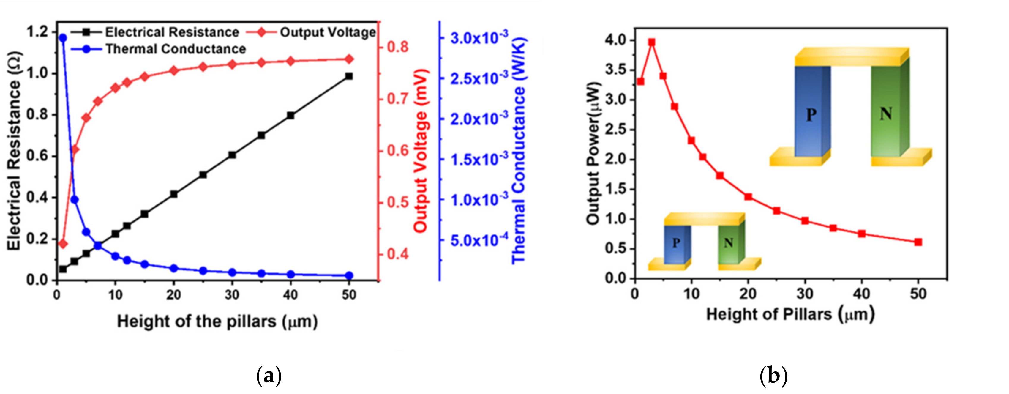
The height of the pillars has a direct role in the electrical resistance and thermal conductance of the device and also has significant importance in the fabrication of the actual device. Devices with different TE pillar heights, ranging from 5 µm to a few hundred µm have been fabricated using micro-fabrication techniques [20,22,25,39,40]. Determination of the TE pillar height is essential for achieving high power outputs, while keeping minimal material usage. In order to determine the ideal height for the device, the micro pillars’ height was varied from 1 µm to 50 µm and was subjected to a temperature gradient of 5 K. The electrical resistance of the legs was evaluated by R = ρL/A, where ρ is the resistivity of the material, L is the length of the pillar and A is the area of the cross-section of the pillar. An increase in the height of the pillar increased the overall electrical resistance of the TEG and decreased the device’s output power. However, the pillar’s lower height tended to exhibit higher thermal conductance, making it difficult to maintain the temperature gradient across the device. The effect of increasing height of the pillar on the electrical resistance and the thermal conductance is shown in Figure 4a. The output voltage developed across the leg pair is also plotted in Figure 4a as a function of the height. The voltage across the leg pairs steadily increased initially with the increase in the leg height and then stabilized upon reaching a height of 10 µm. A similar effect (but decreasing trend) on the thermal conductance can be observed. It is crucial for a TEG device to attain a low thermal conductance to maintain a steady temperature gradient, with a simultaneous decently low electrical resistance of the device. Beyond the 10 µm pillar height, changes in the output voltage and the thermal conductance stayed at a minimum. The output power generated with different pillars height is shown in Figure 4b. A peak output power of 3.96 µW at a height of 3 µm was achieved. However, at this height, the thermal conductance was 0.001 W/K which was 3.33 times higher compared to the conductance for 10 µm pillar height. So, it is difficult to maintain a reasonable temperature gradient for such a small height without any active heat removal strategy. Thereby, the 10 µm pillar height with our reported material properties seems suitable for the desired human body application without compromising much on the device’s output power.
3.3. Interconnect Material Thickness
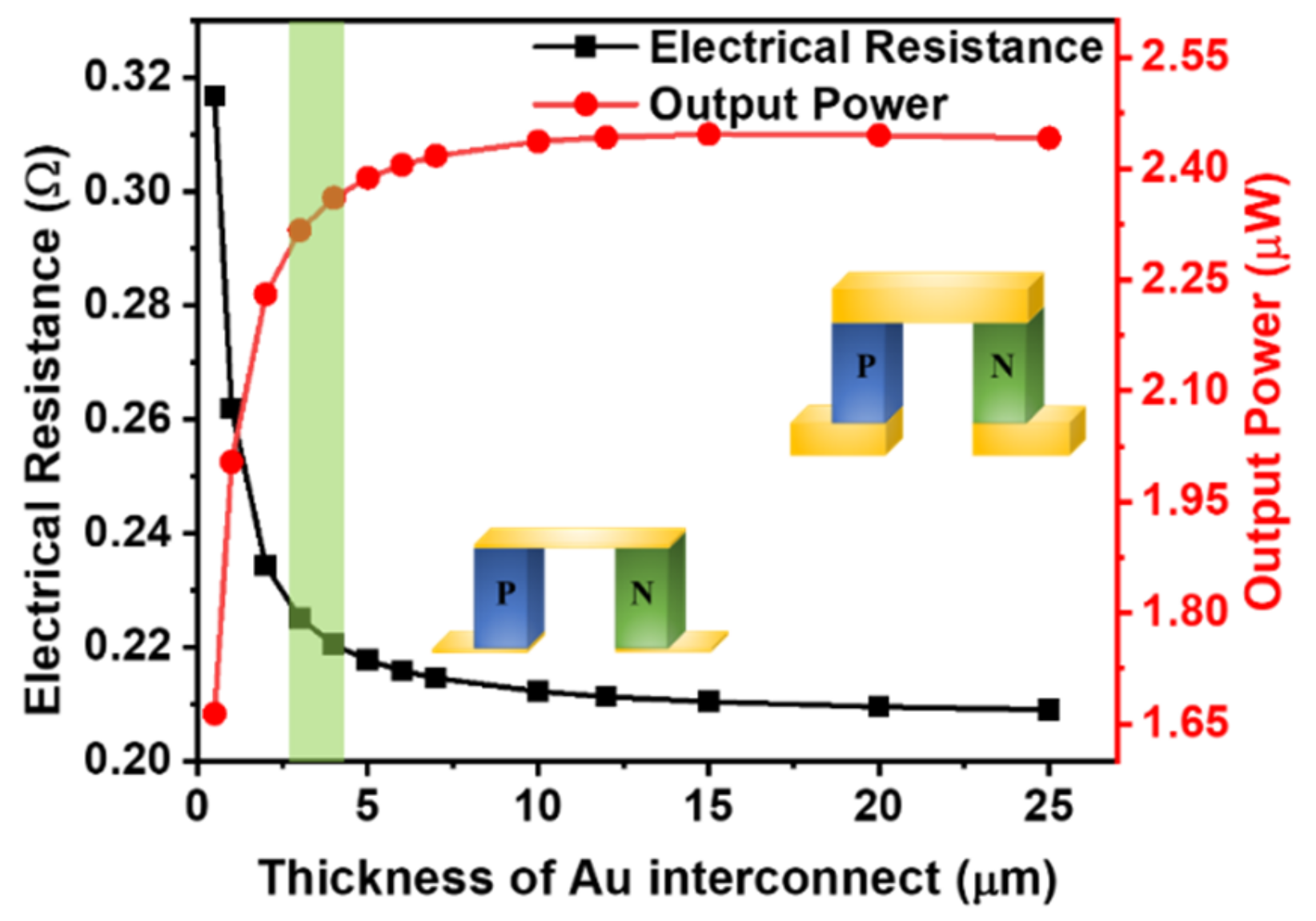
Gold (Au) is the most common interconnect material in micro-TEG devices with excellent electrical and thermal properties. Figure 5 show the influence of the Au thickness on output power and total device resistance (). As expected, the resistance of the device decreases rapidly as the thickness of Au increases, which also increases the output power of the device. When the thickness of the Au interconnect increased beyond 5 µm, the output power improvement became insignificant as the resistance of Au and the total device resistance did not reduce much. Considering the cost of the gold, a 3 µm thickness seems a reasonable compromise for the fabrication of micro-TEG.
3.4. Effect of Filler Material
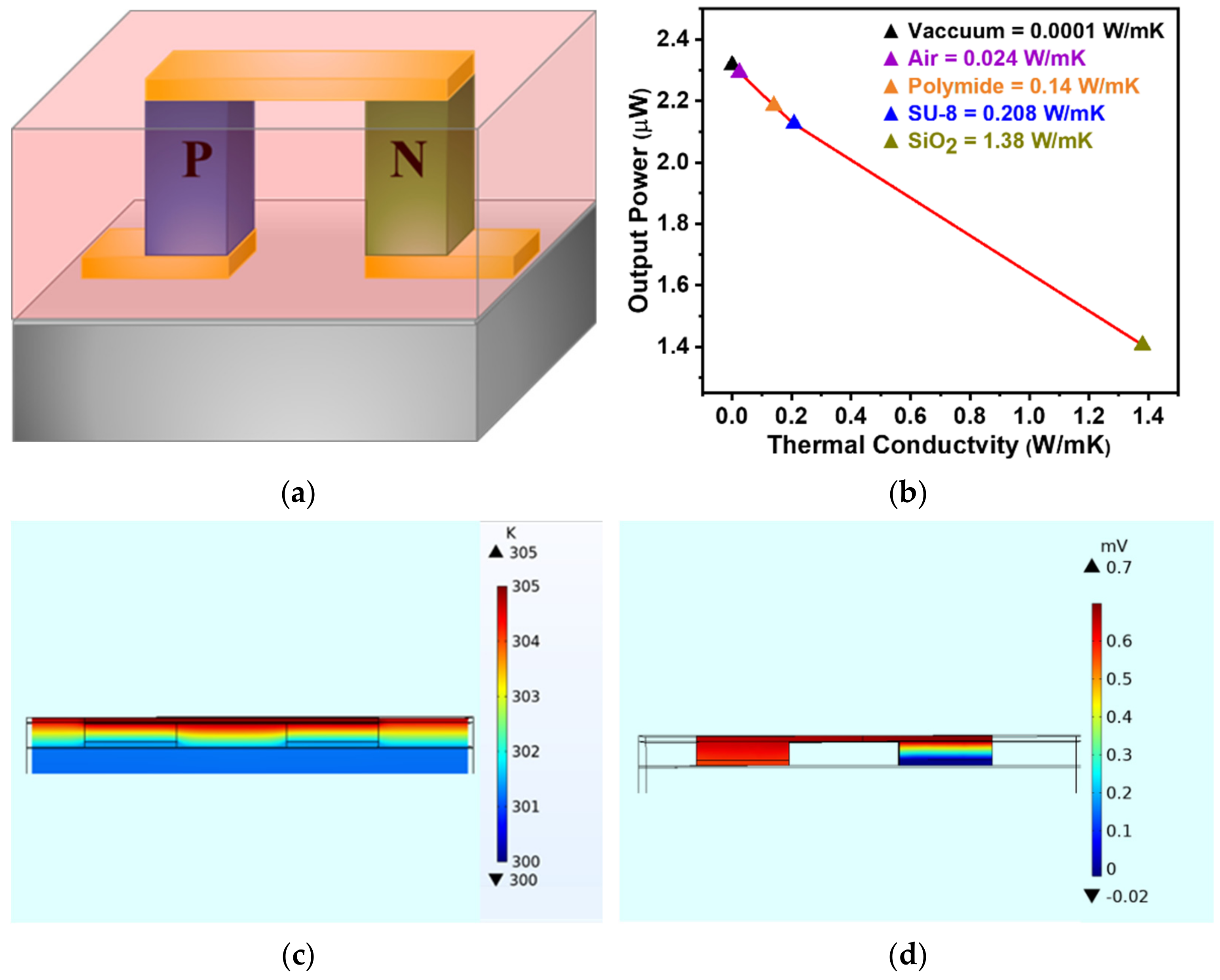
The filler material is usually a non-sacrificial layer during the device fabrication or an intentionally added material for providing structural and mechanical support to the pillars and top interconnect. It is in physical contact to the thermoelectric pillars along with the top and bottom interconnects, which are the hot and cold sides of the device. So, the thermal properties of this material become critically important, as materials with higher thermal conductivity may develop a thermal shunt and reduce the temperature gradient across the device. Figure 6a shows the schematic of thermoelectric leg pair with the filler material. In order to understand the effect of this material on the device performance, five different materials with thermal conductivities ranging from 0.0001 to 1.38 W/mK were investigated [41]. As expected, the single-leg pair’s output power decreased with an increase in the filler materials’ thermal conductivity (Figure 6b).
The highest power output can be achieved by subjecting the device under vacuum, as it has the least thermal conductivity (almost no thermal shunt), but this increases the device packaging cost. Among polyimide, SU-8 photoresist and SiO2, SiO2 showed the lowest power output for the device because of it had the highest thermal conductivity. On the other hand, a device with air as the filler material exhibited 60% higher power output than SiO2 and only 1% less power than the vacuum, making it a preferred choice for the thermoelectric micro-device. Temperature and potential distribution for SiO2 filler materials are shown in Figure 6c and d. It can be observed that keeping the thermal conductivity of the filler materials low as compared to thermoelectric materials is desirable to minimize the predominant heat loss through the filler materials.
3.5. Effect of Ap/An Ratio of the Pillars
The electrical conductivity of the p-type material was 4 times less compared to the n-type material (see Table 1). So, the ratio of the cross-sectional area of the p- and n-type pillars (Ap/An) should be optimized to maximize the performance of the TEG device. The efficiency of the TEG is obtained by:
where, Pout is power output, Qin is the heat flux subjected to the hot side of the device and is given by Equation (9) [31]:
where, I is the circuit current and K is the thermal conductance.
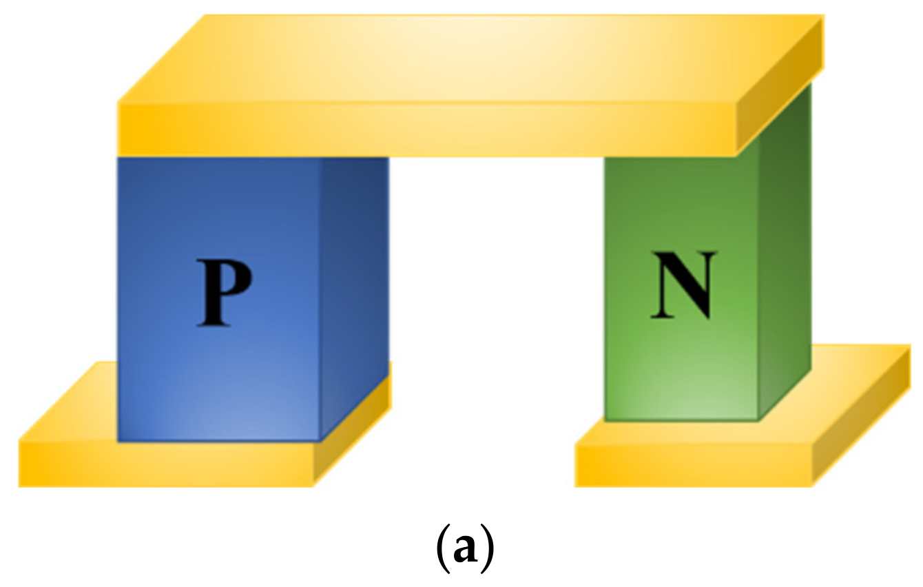
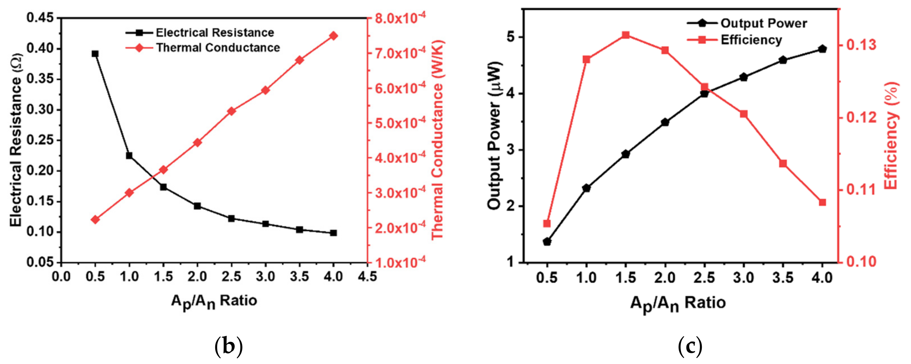
In optimizing the device performance using Ap/An ratio, the cross-sectional area of the n-type leg was kept fixed and the area of the p-type leg was varied, as shown in Figure 7a. Eight different combinations of Ap/An ratios ranging from 0.5 to 4 were modeled, and the results are plotted in Figure 7b,c. With the increase in the cross-sectional area of the p-type leg, the electrical resistance decreased, but the thermal conductance through the device increased (Figure 7b). When the cross-sectional area of the p-type leg was decreased (Ap/An = 0.5), an increased electrical resistance was observed with low thermal conductance of the device. At Ap/An = 4, the electrical resistance was the lowest, which led to the highest output power, but in reality, a much larger cross-sectional area of the p-type leg may not achieve sufficient efficiency because ΔT across the device would be too small because of the high thermal conductance. It is therefore, critically important to balance the cross-sectional area of the legs to obtain a high power output with good efficiency [42].
As the Ap/An ratio increased, the power of single-leg pair TEG increased gradually (Figure 7c); however, the efficiency increased up to 0.131% and then decreased drastically because of the continued increase in the thermal conductance. The output power reached from 1.1 to 4.78 µW, but the efficiency fell by 17.5%
3.6. Module Optimization
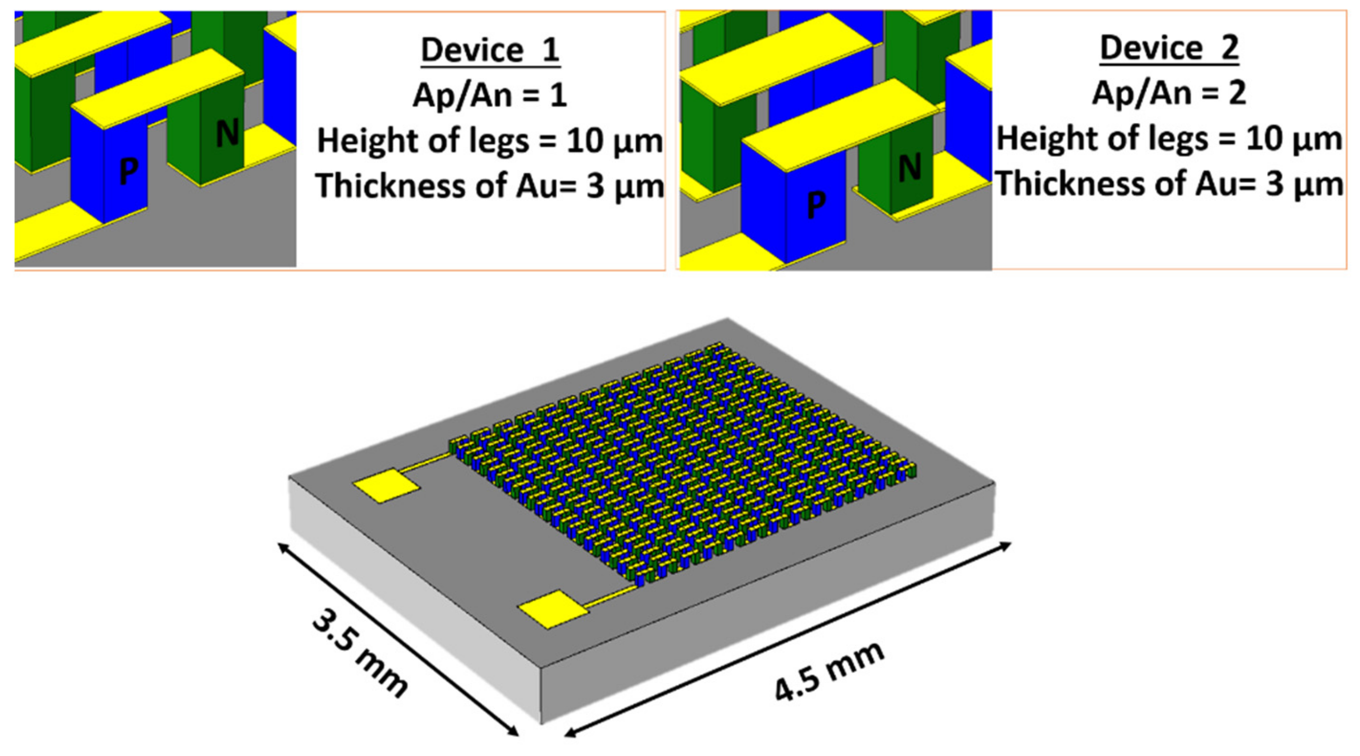
The initial study on single-leg pairs helped in optimizing the geometry of thermoelectric pillars for optimum power output and efficiency, which has been applied in designing and simulating a micro-TEG device with a large number of pillars. For the module optimization, a fixed device area of 3.5 × 4.5 mm2 was defined considering the human body application. In this study, the optimized shape, height, thickness of the interconnect material, filler material and the cross-sectional area of each TE legs obtained from the earlier sections were implemented and are shown in Figure 8.
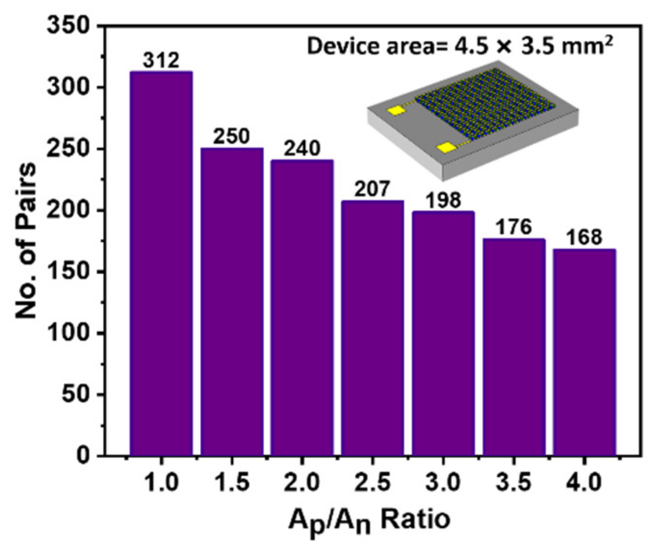
Other geometrical changes (e.g., change of height) have a minimal effect on accommodating the pillars on a fixed area, except the Ap/An ratio of the pillars. The number of TE pillars that can be accommodated while keeping the micro-fabrication design rules in consideration directly impacts the overall device output. Figure 9 showcases the number of leg pairs on a fixed area device at different Ap/An ratios. It is not surprising that a larger Ap/An ratio led to minimizing the number of TE leg pairs in a device when the gap between these pillars was constant.
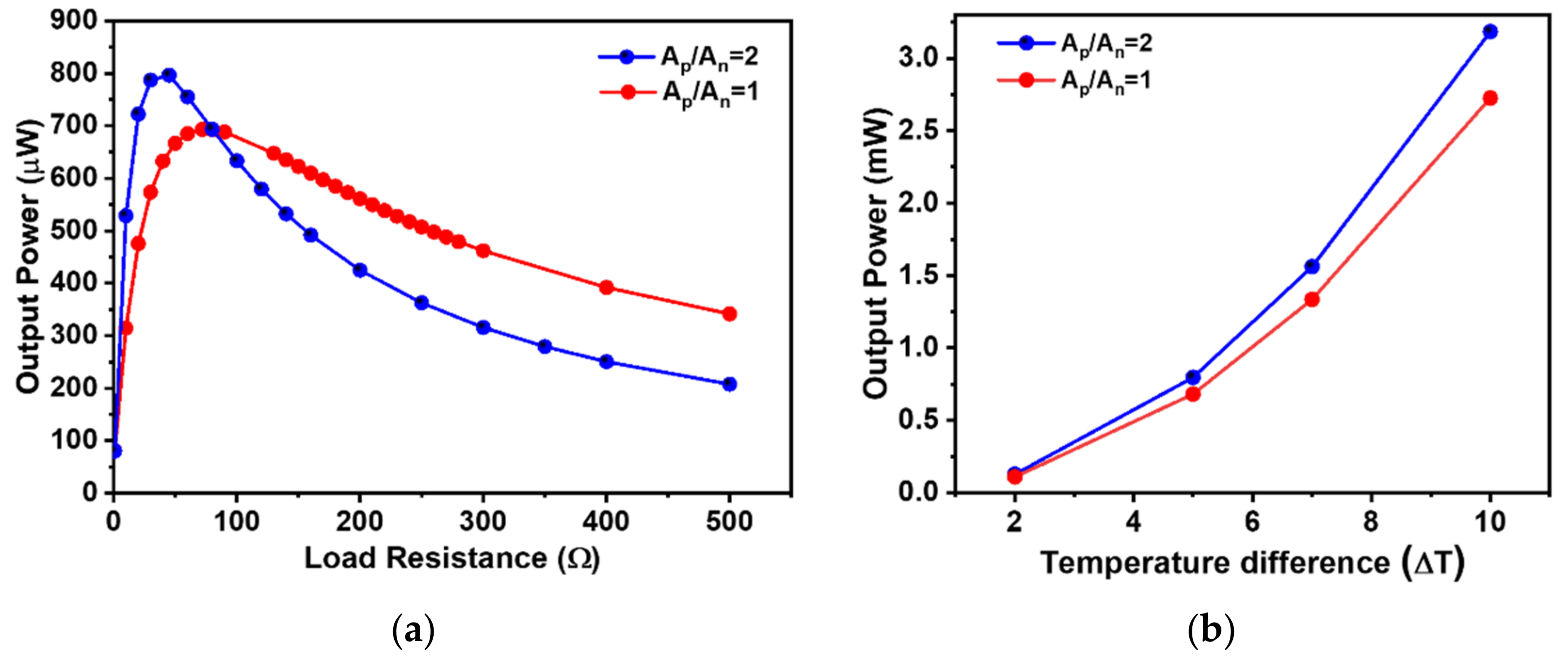
In order to understand and evaluate the device performance, two different Ap/An ratios were mainly considered. The device with a fixed footprint of 3.5×4.5 mm2 constituted 312 TE leg pairs with Ap/An = 1 and 240 leg pairs with Ap/An = 2. The output power for both the devices at the 5 K temperature gradient was plotted against varying load resistance, as shown in Figure 10a. The maximum output power was obtained at = for the individual device.
The effect of both the ratios on the device’s output power was also evaluated at different temperature gradients varying from 2 to 10 K, as shown in Figure 10b. At low-temperature gradients, both the ratios led to similar power outputs. However, with an increased temperature gradient across the device, the Ap/An = 2 led to higher power outputs compared to the Ap/An = 1, although the device with a higher ratio constituted a lesser number of TE pairs. This can be explained from the decreasing overall resistance of the device by increasing the p-type thermoelectric leg’s cross-sectional area, which has a lower electrical conductivity compared to the n-type material. This decrease in the resistance of the device and partial increase of the efficiency led to the higher power output of the device with higher Ap/An ratios compared to the equal area pillars. There was an increasing difference of output power of the devices with increasing temperature gradient. This is due to the fact that the device with a higher ratio had a reduced number of leg pairs, resulting in reduced heat-flow channels, and leading to maintaining larger temperature gradients across the thermoelectric pillars compared to the device with a higher number of TE leg pairs. The optimized device design with an Ap/An ratio 1 delivered a power output of 2.72 mW and the device with an Ap/An ratio 2 led to a power output of 3.18 mW for the 10 K temperature gradient across the device. These power outputs are promising and could power and self-sustain the wearable biomedical system with optimized power management circuits. The power outputs obtained by simulations of the device with the existing TE properties of the materials, while keeping the micro-fabrication process simple, showcase the potential of micro-thermoelectric devices for human wearable applications.
4. Conclusions
We studied and optimized the design of a Si-based micro-thermoelectric generators for wearable applications by three-dimensional model using COMSOL Multiphysics. We can summarize the outcome of this study as follows:
- (1)
- The output power of the square-shaped leg pair was higher than the circular- and hexagon-shaped pillars for a fixed projected area because of its lower electrical resistance compared to others;
- (2)
- The increase in leg height led to a decrease in the output power due to the increase in electrical resistance;
- (3)
- The height of the top and bottom interconnect material was optimized by keeping the fabrication cost constrained;
- (4)
- The filler material between the legs with higher thermal conductivity led to a decrease in the device’s output power due to thermal shunt;
- (5)
- The cross-sectional area of the legs greatly impacted the output power and efficiency of the device. The area of the legs determines the overall thermal conductance and the electrical resistance, and managing both helps in enhancing the overall power output of the device;
- (6)
- The optimized geometrical parameters were applied, and the effect on the overall device was evaluated. The device with an Ap/An ratio 2 outperformed the device with an equal leg cross-section, both in efficiency and power output. Such a device achieved an output power of 0.796 mW and 3.18 mW at the temperature gradients of 5 K and 10 K, respectively.
In the last decades, there has been some good progress in the development of µ-TEGs for low-temperature applications. For example, Bottner et al. [23] fabricated a TEG with 12 thermocouples and measured a maximum power density of 0.059 mW/cm2 at 5 K temperature gradient. In another work, a TEG device was demonstrated with a power density of 1 mW/cm2 at a ΔT of 10 K [22]. A TEG device with 1100 thermocouples has also been reported, which delivered a maximum power density of 7.26 mW/cm2 at a temperature gradient of 7.3 K [25]. In our simulations, we optimized our device with 240 thermocouples and obtained a maximum power density of 9.09, 17.82 and 36.34 mW/cm2 at the temperature gradients of 5, 7 and 10 K, respectively, which is significantly higher than the reported works in the literature.
Thereby, it may be concluded that with standard micro-fabrication techniques, this designed micro-thermoelectric generator can be fabricated. These micro-TEGs should be able to enhance the battery life of wearable and biomedical systems by converting body heat into usable electricity to recharge the battery or even replace the battery entirely for low power applications.
Author Contributions
All authors contributed to the research in this paper. Conceptualization, A.T., S.L. and K.M.R.; methodology, A.T., S.L. and K.M.R.; software, A.T. and S.L.; validation, A.T., S.L. and K.M.R.; writing—original draft preparation, A.T. and S.L.; writing—review and editing, K.M.R.; supervision, K.M.R.; project administration, K.M.R.; funding acquisition, K.M.R. All authors have read and agreed to the published version of the manuscript.
Funding
This work received funding from the European Union’s Horizon 2020 Research and Innovation Programme under Grant Agreement No. 825114 (SmartVista). This publication emanated from research supported in part by a research grant from Science Foundation Ireland (SFI) and was co-funded under the European Regional Development Fund under Grant Number 15/IA/3160, 12/RC/2276 and 13/RC/2077.
Institutional Review Board Statement
Not applicable.
Informed Consent Statement
Not applicable.
Data Availability Statement
The data presented in this study are available on request from the corresponding author. The data are not publicly available due to confidentiality.
Conflicts of Interest
The authors declare no conflict of interest.
References
- Rodriguez-Villegas, E.; Iranmanesh, S.; Imtiaz, S.A. Wearable Medical Devices: High-Level System Design Considerations and Tradeoffs. IEEE Solid State Circuits Mag. 2018, 10, 43–52. [Google Scholar] [CrossRef]
- Dahiya, A.S.; Thireau, J.; Boudaden, J.; Lal, S.; Gulzar, U.; Zhang, Y.; Gil, T.; Azemard, N.; Ramm, P.; Kiessling, T.; et al. Review—Energy Autonomous Wearable Sensors for Smart Healthcare: A Review. J. Electrochem. Soc. 2020, 167, 037516. [Google Scholar] [CrossRef]
- Armand, M.; Tarascon, J.M. Building better batteries. Nature 2008, 451, 652–657. [Google Scholar] [CrossRef] [PubMed]
- Goodenough, J.B.; Kim, Y. Challenges for Rechargeable Li Batteries. Chem. Mater. 2010, 22, 587–603. [Google Scholar] [CrossRef]
- Beidaghi, M.; Gogotsi, Y. Capacitive energy storage in micro-scale devices: Recent advances in design and fabrication of micro-supercapacitors. Energy Environ. Sci. 2014, 7, 867–884. [Google Scholar] [CrossRef]
- Freunberger, S.A.; Chen, Y.; Peng, Z.; Griffin, J.M.; Hardwick, L.J.; Bardé, F.; Novák, P.; Bruce, P.G. Reactions in the Rechargeable Lithium–O2 Battery with Alkyl Carbonate Electrolytes. J. Am. Chem. Soc. 2011, 133, 8040–8047. [Google Scholar] [CrossRef] [PubMed]
- Pan, S.; Ren, J.; Fang, X.; Peng, H. Integration: An Effective Strategy to Develop Multifunctional Energy Storage Devices. Adv. Energy Mater. 2016, 6, 1501867. [Google Scholar] [CrossRef]
- Leonov, V.; Vullers, R.J.M. Wearable electronics self-powered by using human body heat: The state of the art and the perspective. J. Renew. Sustain. Energy 2009, 1, 062701. [Google Scholar] [CrossRef]
- Harris, J.A.; Benedict, F.G. A Biometric Study of Human Basal Metabolism. Proc. Natl. Acad. Sci. USA 1918, 4, 370–373. [Google Scholar] [CrossRef] [Green Version]
- Suarez, F.; Nozariasbmarz, A.; Vashaee, D.; Öztürk, M.C. Designing thermoelectric generators for self-powered wearable electronics. Energy Environ. Sci. 2016, 9, 2099–2113. [Google Scholar] [CrossRef]
- Stark, I. Converting body heat into reliable energy for powering physiological wireless sensors. In Proceedings of the 2nd Conference on Wireless Health, San Diego, CA, USA, 10–13 October 2011. Article 31. [Google Scholar]
- Snyder, G.J.; Toberer, E.S. Complex thermoelectric materials. Nat. Mater. 2008, 7, 105–114. [Google Scholar] [CrossRef]
- Rowe, D.M. CRC Handbook of Thermoelectrics; CRC Press: Boca Raton, FL, USA, 2018. [Google Scholar]
- Nozariasbmarz, A.; Kishore, R.A.; Poudel, B.; Saparamadu, U.; Li, W.; Cruz, R.; Priya, S. High Power Density Body Heat Energy Harvesting. ACS Appl. Mater. Interfaces 2019, 11, 40107–40113. [Google Scholar] [CrossRef]
- Nozariasbmarz, A.; Suarez, F.; Dycus, J.H.; Cabral, M.J.; LeBeau, J.M.; Öztürk, M.C.; Vashaee, D. Thermoelectric generators for wearable body heat harvesting: Material and device concurrent optimization. Nano Energy 2020, 67, 104265. [Google Scholar] [CrossRef]
- Bahk, J.-H.; Fang, H.; Yazawa, K.; Shakouri, A. Flexible thermoelectric materials and device optimization for wearable energy harvesting. J. Mater. Chem. C 2015, 3, 10362–10374. [Google Scholar] [CrossRef]
- Du, Y.; Xu, J.; Paul, B.; Eklund, P. Flexible thermoelectric materials and devices. Appl. Mater. Today 2018, 12, 366–388. [Google Scholar] [CrossRef]
- Wang, Y.; Yang, L.; Shi, X.-L.; Shi, X.; Chen, L.; Dargusch, M.S.; Zou, J.; Chen, Z.-G. Flexible Thermoelectric Materials and Generators: Challenges and Innovations. Adv. Mater. 2019, 31, 1807916. [Google Scholar] [CrossRef] [PubMed]
- Yan, J.; Liao, X.; Yan, D.; Chen, Y. Review of Micro Thermoelectric Generator. J. Microelectromech. Syst. 2018, 27, 1–18. [Google Scholar] [CrossRef]
- Lal, S.; Gautam, D.; Razeeb, K.M. Fabrication of micro-thermoelectric devices for power generation and the thermal management of photonic devices. J. Micromech. Microeng. 2019, 29, 065015. [Google Scholar] [CrossRef]
- Lal, S.; Gautam, D.; Razeeb, K.M. Fabrication of micro-thermoelectric cooler for the thermal management of photonic devices. In Proceedings of the 2018 IEEE 18th International Conference on Nanotechnology (IEEE-NANO), Cork, Ireland, 23–26 July 2018; pp. 1–2. [Google Scholar]
- Zhang, W.; Yang, J.; Xu, D. A high power density micro-thermoelectric generator fabricated by an integrated bottom-up approach. J. Microelectromech. Syst. 2016, 25, 744–749. [Google Scholar] [CrossRef]
- Bottner, H.; Nurnus, J.; Gavrikov, A.; Kuhner, G.; Jagle, M.; Kunzel, C.; Eberhard, D.; Plescher, G.; Schubert, A.; Schlereth, K. New thermoelectric components using microsystem technologies. J. Microelectromech. Syst. 2004, 13, 414–420. [Google Scholar] [CrossRef]
- Glatz, W.; Muntwyler, S.; Hierold, C. Optimization and fabrication of thick flexible polymer based micro thermoelectric generator. Sens. Actuators A Phys. 2006, 132, 337–345. [Google Scholar] [CrossRef]
- Dunham, M.T.; Barako, M.T.; Cornett, J.E.; Gao, Y.; Haidar, S.; Sun, N.; Asheghi, M.; Chen, B.; Goodson, K.E. Experimental Characterization of Microfabricated Thermoelectric Energy Harvesters for Smart Sensor and Wearable Applications. Adv. Mater. Technol. 2018, 3, 1700383. [Google Scholar] [CrossRef]
- Kim, M.-Y.; Oh, T.-S. Thermoelectric Power Generation Characteristics of a Thin-Film Device Consisting of Electrodeposited n-Bi2Te3 and p-Sb2Te3 Thin-Film Legs. J. Electron. Mater. 2013, 42, 2752–2757. [Google Scholar] [CrossRef]
- Grasso, S.; Tsujii, N.; Jiang, Q.; Khaliq, J.; Maruyama, S.; Miranda, M.; Simpson, K.; Mori, T.; Reece, M.J. Ultra low thermal conductivity of disordered layered p-type bismuth telluride. J. Mater. Chem. C 2013, 1, 2362–2367. [Google Scholar] [CrossRef]
- Khaliq, J.; Jiang, Q.; Yang, J.; Simpson, K.; Yan, H.; Reece, M.J. Utilizing the phonon glass electron crystal concept to improve the thermoelectric properties of combined Yb-stuffed and Te-substituted CoSb3. Scr. Mater. 2014, 72–73, 63–66. [Google Scholar] [CrossRef]
- Padmanathan, N.; Lal, S.; Gautam, D.; Razeeb, K.M. Amorphous Framework in Electrodeposited CuBiTe Thermoelectric Thin Films with High Room-Temperature Performance. ACS Appl. Electron. Mater. 2021. [Google Scholar] [CrossRef]
- Lara Ramos, D.A.; Barati, V.; Garcia, J.; Reith, H.; Li, G.; Pérez, N.; Schierning, G.; Nielsch, K. Design Guidelines for Micro-Thermoelectric Devices by Finite Element Analysis. Adv. Sustain. Syst. 2019, 3, 1800093. [Google Scholar] [CrossRef]
- Wang, J.; Li, Y.; Zhao, C.; Cai, Y.; Zhu, L.; Zhang, C.; Wang, J.; Zhao, W.; Cao, P. An optimization study of structural size of parameterized thermoelectric generator module on performance. Energy Convers. Manag. 2018, 160, 176–181. [Google Scholar] [CrossRef]
- Thimont, Y.; LeBlanc, S. The impact of thermoelectric leg geometries on thermal resistance and power output. J. Appl. Phys. 2019, 126, 095101. [Google Scholar] [CrossRef] [Green Version]
- Wang, L.; Li, K.; Zhang, S.; Liu, C.; Zhang, Z.; Chen, J.; Gu, M. Modeling the Effects of Module Size and Material Property on Thermoelectric Generator Power. ACS Omega 2020, 5, 29844–29853. [Google Scholar] [CrossRef]
- Lal, S.; Gautam, D.; Razeeb, K.M. Optimization of annealing conditions to enhance thermoelectric performance of electrodeposited p-type BiSbTe thin films. APL Mater. 2019, 7, 031102. [Google Scholar] [CrossRef] [Green Version]
- Lal, S.; Razeeb, K.M.; Gautam, D. Enhanced Thermoelectric Properties of Electrodeposited Cu-Doped Te Films. ACS Appl. Energy Mater. 2020, 3, 3262–3268. [Google Scholar] [CrossRef]
- Zhang, Q.; Liao, J.; Tang, Y.; Gu, M.; Ming, C.; Qiu, P.; Bai, S.; Shi, X.; Uher, C.; Chen, L. Realizing a thermoelectric conversion efficiency of 12% in bismuth telluride/skutterudite segmented modules through full-parameter optimization and energy-loss minimized integration. Energy Environ. Sci. 2017, 10, 956–963. [Google Scholar] [CrossRef]
- Enescu, D. Thermoelectric Energy Harvesting: Basic Principles and Applications. In Green Energy Advances; IntechOpen: London, UK, 2019. [Google Scholar]
- Corbett, S.; Gautam, D.; Lal, S.; Yu, K.; Balla, N.; Cunningham, G.; Razeeb, K.M.; Enright, R.; McCloskey, D. Electrodeposited Thin-Film Micro-Thermoelectric Coolers with Extreme Heat Flux Handling and Microsecond Time Response. ACS Appl. Mater. Interfaces 2021, 13, 1773–1782. [Google Scholar] [CrossRef]
- Snyder, G.J.; Lim, J.R.; Huang, C.-K.; Fleurial, J.-P. Thermoelectric microdevice fabricated by a MEMS-like electrochemical process. Nat. Mater. 2003, 2, 528–531. [Google Scholar] [CrossRef] [PubMed]
- Roth, R.; Rostek, R.; Cobry, K.; Köhler, C.; Groh, M.; Woias, P. Design and Characterization of Micro Thermoelectric Cross-Plane Generators With Electroplated Bi2Te3, SbxTey, and Reflow Soldering. J. Microelectromech. Syst. 2014, 23, 961–971. [Google Scholar] [CrossRef]
- Dunham, M.T.; Barako, M.T.; LeBlanc, S.; Asheghi, M.; Chen, B.; Goodson, K.E. Power density optimization for micro thermoelectric generators. Energy 2015, 93, 2006–2017. [Google Scholar] [CrossRef] [Green Version]
- Qiu, P.; Mao, T.; Huang, Z.; Xia, X.; Liao, J.; Agne, M.T.; Gu, M.; Zhang, Q.; Ren, D.; Bai, S.; et al. High-Efficiency and Stable Thermoelectric Module Based on Liquid-Like Materials. Joule 2019, 3, 1538–1548. [Google Scholar] [CrossRef]
Figure 1.
Schematic of single‒leg pair TEG.

Figure 2.
(a) Single‒leg pair TEGs with different shapes of the pillars; (b) output power when the cross‒sectional area of different pillar shapes are constant, and (c) output power vs. load resistance for different pillar shapes at 5 K temperature gradient with varied cross‒sectional areas (keeping the effective area of the device constant).

Figure 3.
(a) Temperature distribution of square‒shaped leg pair TEG; (b) potential distribution across the device in square‒shaped leg pair TEG.
Figure 3.
(a) Temperature distribution of square‒shaped leg pair TEG; (b) potential distribution across the device in square‒shaped leg pair TEG.

Figure 4.
(a) Electrical resistance, output voltage and thermal conductance vs. pillars’ height at 5 K temperature gradient; (b) power output as a function of pillars’ height at 5 K temperature gradient.
Figure 4.
(a) Electrical resistance, output voltage and thermal conductance vs. pillars’ height at 5 K temperature gradient; (b) power output as a function of pillars’ height at 5 K temperature gradient.

Figure 5.
Electrical resistance and output power as a function of interconnect material thickness at 5 K temperature gradient.
Figure 5.
Electrical resistance and output power as a function of interconnect material thickness at 5 K temperature gradient.

Figure 6.
(a) Schematic of a single‒leg pair TEG with SiO2 as filler material; (b) power output of single‒leg pair TEG with different filler materials; (c) temperature; and (d) potential distribution of single‒leg pair TEG with SiO2 as filler material.
Figure 6.
(a) Schematic of a single‒leg pair TEG with SiO2 as filler material; (b) power output of single‒leg pair TEG with different filler materials; (c) temperature; and (d) potential distribution of single‒leg pair TEG with SiO2 as filler material.

Figure 7.
(a) Schematic of single‒leg pair TEG with a different cross‒sectional area of p‒ and n‒type legs; (b) electrical resistance and thermal conductance of single‒leg pair as a function of Ap/An ratio; (c) power output and efficiency of single‒leg pair for different Ap/An ratio.
Figure 7.
(a) Schematic of single‒leg pair TEG with a different cross‒sectional area of p‒ and n‒type legs; (b) electrical resistance and thermal conductance of single‒leg pair as a function of Ap/An ratio; (c) power output and efficiency of single‒leg pair for different Ap/An ratio.


Figure 8.
Schematic diagram of optimized devices.

Figure 9.
Numbers of leg pairs for each Ap/An ratio devices.

Figure 10.
(a) Output power vs. load resistance for Ap/An = 1 and Ap/An = 2 devices at 5 K temperature gradient. (b) Power output for Ap/An = 1 and Ap/An = 2 devices at different temperature gradients.
Figure 10.
(a) Output power vs. load resistance for Ap/An = 1 and Ap/An = 2 devices at 5 K temperature gradient. (b) Power output for Ap/An = 1 and Ap/An = 2 devices at different temperature gradients.


Table 1.
Thermoelectric material properties measured at 300 K used for the simulations.
| Materials | Electrical Conductivity (Sm−1) | Seebeck Coefficient (µVK−1) | Thermal Conductivity (Wm−1K−1) | Reference |
|---|---|---|---|---|
| CuTe (n-type) | 104 | −227.0 | 0.6 | [35] |
| BiSbTe (p-type) | 104 | 90.5 | 0.6 | [34] |
| Gold | 106 | 6.5 | 317.0 | [30] |
| Silicon Dioxide | Electrically isolated | Electrically isolated | 1.4 | |
| Silicon | Electrically isolated | Electrically isolated | 130.0 | [30] |
Publisher’s Note: MDPI stays neutral with regard to jurisdictional claims in published maps and institutional affiliations. |
© 2021 by the authors. Licensee MDPI, Basel, Switzerland. This article is an open access article distributed under the terms and conditions of the Creative Commons Attribution (CC BY) license (https://creativecommons.org/licenses/by/4.0/).
Share and Cite
MDPI and ACS Style
Tanwar, A.; Lal, S.; Razeeb, K.M. Structural Design Optimization of Micro-Thermoelectric Generator for Wearable Biomedical Devices. Energies 2021, 14, 2339. https://0-doi-org.brum.beds.ac.uk/10.3390/en14082339
AMA Style
Tanwar A, Lal S, Razeeb KM. Structural Design Optimization of Micro-Thermoelectric Generator for Wearable Biomedical Devices. Energies. 2021; 14(8):2339. https://0-doi-org.brum.beds.ac.uk/10.3390/en14082339
Chicago/Turabian StyleTanwar, Amit, Swatchith Lal, and Kafil M. Razeeb. 2021. "Structural Design Optimization of Micro-Thermoelectric Generator for Wearable Biomedical Devices" Energies 14, no. 8: 2339. https://0-doi-org.brum.beds.ac.uk/10.3390/en14082339
Note that from the first issue of 2016, this journal uses article numbers instead of page numbers. See further details here.