
Physicochemical Characterization of Phase Change Materials for Industrial Waste Heat Recovery Applications


Abstract
:1. Introduction
2. Materials and Methods
3. Results and Discussion
4. Conclusions
Author Contributions
Funding
Institutional Review Board Statement
Informed Consent Statement
Acknowledgments
Conflicts of Interest
References
- Brueckner, S.; Liu, S.; Miro, L.; Radspieler, M.; Cabeza, L.F.; Laevemman, E. Industrial waste heat recovery technologies: An economic analysis of heat transformation technologies. Appl. Energy 2015, 151, 157–167. [Google Scholar] [CrossRef]
- Miró, L.; Brückner, S.; Cabeza, L.F. Mapping and discussing Industrial Waste Heat (IWH) potentials for different countries. Renew. Sustain. Energy Rev. 2015, 51, 847–855. [Google Scholar] [CrossRef] [Green Version]
- International Energy Agency (IEA). Available online: https://www.iea.org/articles/improving-industrial-waste-heat-recovery (accessed on 24 March 2022).
- Hammond, G.P.; Norman, J.B. Heat recovery opportunities in UK industry. Appl. Energy 2014, 116, 387–397. [Google Scholar] [CrossRef] [Green Version]
- Oró, E.; de Gracia, A.; Castell, A.; Farid, M.M.; Cabeza, L.F. Review on phase change materials (PCMs) for cold thermal energy storage applications. Appl. Energy 2012, 99, 513–533. [Google Scholar] [CrossRef] [Green Version]
- Miro, L.; Gasia, J.; Cabeza, L.F. Thermal energy storage (TES) for industrial waste heat (IWH) recovery: A review. Appl. Energy 2016, 179, 284–301. [Google Scholar] [CrossRef] [Green Version]
- Du, K.; Calautit, J.; Eames, P.; Wu, Y. A state-of-the-art review of the application of phase change materials (PCM) in Mobilized-Thermal Energy Storage (M-TES) for recovering low-temperature industrial waste heat (IWH) for distributed heat supply. Renew. Energy 2021, 168, 1040–1057. [Google Scholar] [CrossRef]
- Nomura, T.; Okinaka, N.; Akiyama, T. Waste heat transportation system, using phase change material (PCM) from steelworks to chemical plant. Resour. Conserv. Recycl. 2010, 54, 1000–1006. [Google Scholar] [CrossRef]
- Nazir, H.; Batool, M.; Bolivar, F.J.; Isaza-Ruiz, M.; Xu, X.; Vignarooban, K.; Phelan, P.; Inamudding; Kannan, A.M. Recent developments in phase change materials for energy storage applications: A review. Int. J. Heat Mass Transf. 2019, 129, 491–523. [Google Scholar] [CrossRef]
- Mehling, H.; Cabeza, L.F. Heat and Cold Storage with PCM; Springer: Berlin, Germany, 2008. [Google Scholar]
- Larrinaga, P.; Campos-Celador, A.; Legarreta, J.; Diarce, G. Evaluation of the theoretical, technical and economic potential of industrial waste heat recovery in the Basque Country. J. Clean. Prod. 2021, 312, 127494. [Google Scholar] [CrossRef]
- Fernandez, A.G.; Boquera, L.; Cabeza, L.F. Characterization of materials for sensible thermal energy storage at high temperature. In Recent Advancements in Materials and Systems for Thermal Energy Storage. An Introduction to Experimental Characterization Methods; Springer: Cham, Switzerland, 2019; pp. 69–88. ISBN 1865-3529. [Google Scholar]
- Fernandez, A.G.; Gomez-vidal, J.; Oro, E.; Kruizenga, A.; Sole, A.; Cabeza, L.F. Mainstreaming commercial CSP systems: A technology review. Renew. Energy 2019, 140, 152–176. [Google Scholar] [CrossRef]
- Gil, A.; Medrano, M.; Martorell, I.; Lazaro, A.; Dolado, P.; Zalba, B.; Cabeza, L.F. State of the art on high temperature thermal energy storage for power generation. Part 1: Concepts, materials and modellization. Renew. Sustain. Energy Rev. 2010, 14, 31–55. [Google Scholar] [CrossRef]
- Maldonado, M.; Fernández, A.G.; Cabeza, L.F. Corrosion Assessment of Myo-Inositol Sugar Alcohol as a Phase Change Material in Storage Systems Connected to Fresnel Solar Plants. Molecules 2019, 24, 1383. [Google Scholar] [CrossRef] [PubMed] [Green Version]
- Ruiz-Cabañas, F.J.; Jové, A.; Prieto, C.; Madina, V.; Fernández, A.I.; Cabeza, L.F. Materials selection of steam-phase change material (PCM) heat exchanger for thermal energy storage systems in direct steam generation facilities. Sol. Energy Mater. Sol. Cells 2017, 159, 526–535. [Google Scholar] [CrossRef] [Green Version]
- Kuravi, S.; Trahan, J.; Goswami, D.Y.; Rahman, M.M.; Stefanakos, E.K. Thermal energy storage technologies and systems for concentrating solar power plants. Prog. Energy Combust. Sci. 2013, 39, 285–319. [Google Scholar] [CrossRef]
- Porisini, F.C. Salt hydrates used for latent heat storage: Corrosion of metals and reliability of thermal performance. Sol. Energy 1988, 41, 193–197. [Google Scholar] [CrossRef]
- Cabeza, L.F.; Illa, J.; Roca, J.; Badia, F.; Mehling, H.; Hiebler, S.; Ziegler, F. Immersion corrosion tests on metal-salt hydrate pairs used for latent heat storage in the 32 to 36 °C temperature range. Werkst. Korros. 2001, 52, 140. [Google Scholar] [CrossRef]
- Cabeza, L.F.; Mehling, H.; Hiebler, S. Immersion corrosion tests on metal-salt hydrate pairs used for latent heat storage in the 48 to 58 °C temperature range. Mater. Corros. 2002, 53, 902–907. [Google Scholar] [CrossRef]
- Fernández, A.G.; Rey, A.; Lasanta, M.I.; Mato, S.; Brady, M.P.; Perez, F.J. Corrosion of alumina-forming austenitic steel in molten nitrate salts by gravimetric analysis and impedance spectroscopy. Mater. Corros. 2014, 65, 267–275. [Google Scholar] [CrossRef]
- Yamamoto, Y.; Takyana, M.; Lu, Z.; Liu, C.; Evans, N.; Maziasz, P.; Brady, M.P. Alloying effects on creep and oxidation resistance of austenitic stainless steel alloys employing intermetallic precipitates. Intermetallics 2008, 16, 453–462. [Google Scholar] [CrossRef]
- Brady, M.P.; Magee, J.; Yamamoto, Y.; Helmick, D.; Wang, L. Co-optimization of wrought alumina-forming austenitic stainless steel composition ranges for high-temperature creep and oxidation/corrosion resistance. Mater. Sci. Eng. A 2014, 590, 101–115. [Google Scholar] [CrossRef]
- Fernández, A.G.; Pineda, F.; Fuentealba, E.; Jullian, D.; Mallco, A.; Walczak, M. Compatibility of alumina forming alloys with LiNO3-containing molten salts for solar thermal plants. J. Energy Storage 2022, 48, 103988. [Google Scholar] [CrossRef]
- Fernández, A.G.; Pineda, F.; Walczak, M.; Cabeza, L.F. Corrosion evaluation of alumina-forming alloys in carbonate molten salt for CSP plants. Renew. Energy 2019, 140, 227–233. [Google Scholar] [CrossRef]
- Fernández, A.G.; Cabeza, L.F. Anodic protection assessment using alumina forming alloys in chloride molten salt for CSP plants. Coatings 2020, 10, 138. [Google Scholar] [CrossRef] [Green Version]
- ASTM G1-03; Standard Practice for Preparing, Cleaning, and Evaluating Corrosion Test Specimens. ASTM International: West Conshohocken, PA, USA, 2017.
- ISO 6892-1; Metallic Materials—Tensile Testing—Part 1: Method of Test at Room Temperature. International Organization for Standardization: Geneva, Switzerland, 2009.
- Raznoshinskaia, A.; Troyanovskaya, I.; Kozminykh, V. Heat-storing phase-change materials: Influence of thermophysical properties on stabilization of exhaust temperature. Mater. Today Proc. 2019, 19, 1831–1834. [Google Scholar] [CrossRef]
- Ghali, E.; Vedula, S.; Sastri, E.; Elboujdaini, M. Corrosion Prevention and Protection: Practical Solutions; John Wiley & Sons: Hoboken, NJ, USA, 2007; Available online: https://0-www-wiley-com.brum.beds.ac.uk/en-us/Corrosion+Prevention+and+Protection%3A+Practical+Solutions-p-9780470024027 (accessed on 29 March 2022).


| Thermophysical | Kinetic | Chemical | Others |
|---|---|---|---|
| -Melting/solidification temperatures in the application range | -Supercooling reduced | -Thermal stability/reliability | -Low cost |
| -High heat capacity | -Low toxicity | ||
| -High thermal conductivity | -High crystallization rate | -Low corrosion with the container materials | -Sustainability |
| Alloy | Weight % | |||||||||||||||
|---|---|---|---|---|---|---|---|---|---|---|---|---|---|---|---|---|
| Fe | C | Mn | Si | P | S | Cr | Ni | Cu | Ti | Al | Mo | Co | V | Nb | N | |
| OC4 | 47.43 | 0.89 | 1.80 | 0.22 | 0.06 | 0.01 | 13.88 | 26.16 | 0.57 | 0.01 | 4.28 | 2.24 | 0.08 | 0.06 | 2.27 | 0.04 |
| Phase Change Material | Melting Point (°C) | Solidification Point (°C) | Fusion Enthalpy (kJ/kg) | Heat Capacity (J/g K) [29] |
|---|---|---|---|---|
| NaNO3 | 299.0 | 283.5 | 201.6 | 1.83 |
| KNO3 | 317.5 | 292.3 | 92.2 | 1.48 |
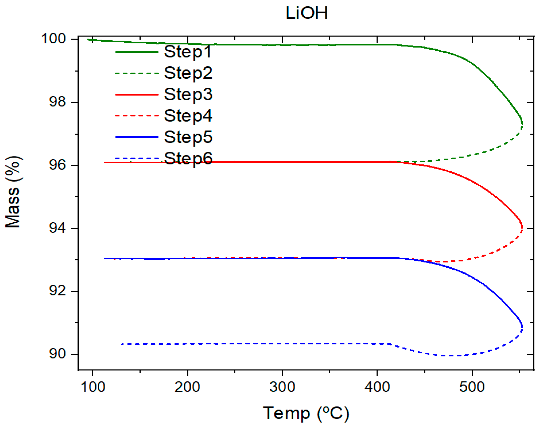
| LiOH | 413.1 | 391.5 | Not applicable | 3.90 |
| KOH | 345.6 | 336.4 | 81.6 | 2.09 |
| mg/cm2 yr. | mm/yr. | Recommendation |
|---|---|---|
| >1000 | 2 | Completely destroyed with |
| 100 to 999 | 0.2–1.99 | Not recommended for service (>a month) |
| 50 to 99 | 0.1–0.19 | Not recommended for service (>one year) |
| 10 to 49 | 0.02–0.09 | Caution recommended, based on the specific application |
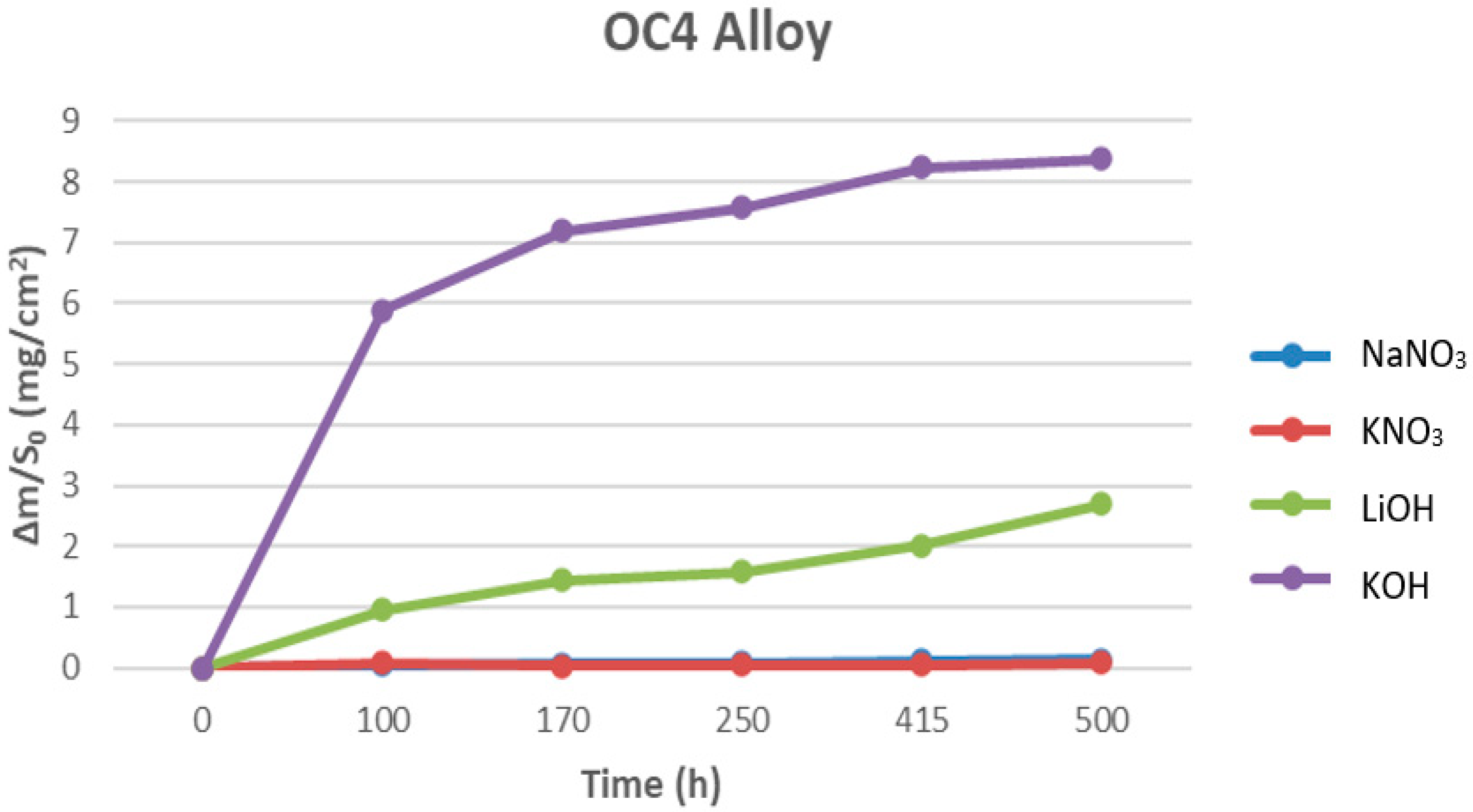
| 0.3 to 9.9 | <0.02 | Recommended for long-term service |
Publisher’s Note: MDPI stays neutral with regard to jurisdictional claims in published maps and institutional affiliations. |
© 2022 by the authors. Licensee MDPI, Basel, Switzerland. This article is an open access article distributed under the terms and conditions of the Creative Commons Attribution (CC BY) license (https://creativecommons.org/licenses/by/4.0/).
Share and Cite
Fernández, A.G.; González-Fernández, L.; Grosu, Y.; Labidi, J. Physicochemical Characterization of Phase Change Materials for Industrial Waste Heat Recovery Applications. Energies 2022, 15, 3640. https://0-doi-org.brum.beds.ac.uk/10.3390/en15103640
Fernández AG, González-Fernández L, Grosu Y, Labidi J. Physicochemical Characterization of Phase Change Materials for Industrial Waste Heat Recovery Applications. Energies. 2022; 15(10):3640. https://0-doi-org.brum.beds.ac.uk/10.3390/en15103640
Chicago/Turabian StyleFernández, Angel G., Luis González-Fernández, Yaroslav Grosu, and Jalel Labidi. 2022. "Physicochemical Characterization of Phase Change Materials for Industrial Waste Heat Recovery Applications" Energies 15, no. 10: 3640. https://0-doi-org.brum.beds.ac.uk/10.3390/en15103640