
Luenberger Observer-Based Microgrid Control Strategy for Mixed Load Conditions

College of Electrical and Control Engineering, Xi’an University of Science and Technology, Xi’an 710054, China
*
Author to whom correspondence should be addressed.
Energies 2022, 15(10), 3655; https://0-doi-org.brum.beds.ac.uk/10.3390/en15103655
Submission received: 11 March 2022
/
Revised: 1 May 2022
/
Accepted: 5 May 2022
/
Published: 16 May 2022
(This article belongs to the Special Issue Next Generation Energy and Propulsion Systems for Transportation Electrification)
Abstract
:In this paper, a Luenberger observer-based microgrid control strategy is proposed to enhance the power quality of microgrids, when the grid loads are mixed and strongly non-linear. To improve performance under this condition, a Luenberger observer is designed for three phase power grids. On the basis of the observer, the components of different frequencies and sequences of voltages and currents are obtained accurately. The virtual impedance of different frequencies and sequences is designed, which makes the equivalent line impedance meet the power-sharing condition, reducing the fundamental negative sequence voltages and harmonic voltages. The active power droop equation, meanwhile, is proposed, where the bus voltage is modified. The value range of virtual impedance is discussed in the complex frequency domain. The proposed control strategy does not require any communication lines, so the hardware structure is simplified. The simulations and experiments are provided to verify the effectiveness of the proposed method.
1. Introduction
With the impact of the energy crisis and concerns about carbon emissions, new energy power generations have developed rapidly [1,2]. The microgrid is composed of loads, distributed generators (DG), energy storage equipment, power electronic devices, measurements, monitoring and protection devices. It has been built and put into the application in islands, remote areas, commercial enterprises, campuses, and industrial power [3,4,5]. It can be connected to the grid or operated on an island. The power distribution of the distributed power sources of the microgrid under island operation is particularly important, and because there is no frequency and voltage support of the large grid, its electricity quality has many problems [6,7].
Nowadays, droop control has been widely employed in microgrid inverter control [8]. Because the line impedance is difficult to meet the power-sharing condition, the output power distribution of traditional droop control is disproportion [9,10]. Some scholars introduce virtual impedance technology into droop control and conduct a lot of research on DG power-sharing [11,12,13,14,15,16,17,18,19,20,21,22]. An intermediate instantaneous droop control loop is adopted to fix the output impedance in [11], hence, achieving excellent power balance when sharing linear or non-linear loads. A novel virtual impedance implementation method in terms of a second-order general-integrator (SOGI) algorithm is proposed for parallel inverter systems without communication signals in [12]. For the sake of achieving accurate power-sharing and improving voltage quality without the impact of hardware parameter variations, a novel voltage stabilization and power-sharing control method is studied in [13], which is on the basis of the virtual complex impedance. Paper [14] considers the impact of current harmonics in islanded and grid-connected microgrids. The virtual impedance is applied to the equal distribution of the harmonic power of the island microgrid and improved the output current when connected to the grid. An adaptive virtual impedance control method is proposed based on the injection of an extra small AC signal (SACS) in the output voltage of each inverter in [15], which achieves power-sharing in a steady-state. The virtual impedance proposed in [16] is modified by the feed-forward terms of DG line current and the point of common coupling (PCC) voltage at the fundamental frequency and harmonic frequency respectively, and the communication system is introduced simultaneously. In [17], a control strategy that does not require recognition of line parameters and the employment of conventional droop is proposed. Nevertheless, this strategy still requires communication between DG and the PCC. Paper [18] proposes an enhanced virtual harmonic impedance control scheme to compensate for the PCC voltage harmonics without harmonic power-sharing error for islanded microgrids. Whereas it is aimed at single-phase systems and requires a central controller and its communication with the DG. In [19], an adaptive virtual impedance control method is applied to DG units in islanded microgrids. However, this control strategy still requires the central controller and its communication with the DG. Paper [20] introduces a kind of harmonic droop control to realize harmonic power-sharing. In [21], the paper proposes an adaptive Virtual Synchronous Generator (VSG) control method based on virtual impedance. The virtual resistance is adaptively designed according to the operating point of the microgrid. However, the control performance under mixed load is not considered. Paper [22] adopts a virtual impedance tuning method based on a successive approximation to accurately compensate for the mismatch among line impedances. To realize this strategy, a common triggering signal from the microgrid central controller is indispensable to start the internal time sequence of each DG unit. [16,22] requires a communication system, which increases the complexity and cost of the system.
This paper proposes a control strategy for island microgrid under mixed load, which is different from other methods as follows. Firstly, the mathematical model of three-phase current is established, the Luenberger observer of three-phase current is designed and its stability is proved. Based on the observer configuration of virtual impedances of different frequencies and sequences, the inverter output power is equally divided and the unbalanced voltage and harmonic voltage of the PCC are reduced. Secondly, the value range of the virtual impedance is discussed. At the h-order frequency, with harmonic voltage as input and harmonic current as output, the root locus of the virtual resistance is obtained. Analyzing the root locus, it is concluded that the critical value of the virtual resistance should be its corresponding line resistance value. Finally, the active power droop control with voltage compensation is employed to increase the PCC voltage. The effectiveness of the control strategy is verified under different load conditions in both simulation and experiment.
The paper is arranged as below. In Section 2, they are introduced, which are the structure of the system and analyzed the employment of virtual impedance to achieve power-sharing and improve power quality. In Section 3, it is established that the three-phase current mathematical model, its Luenberger observer, and the stability are derived. In Section 4, the control strategy structure is discussed. The value range of the harmonic virtual impedance is analyzed and the droop control with voltage compensation is deducted. The simulation and experiment of two inverters without communication in parallel are performed in Section 5 and Section 6, respectively, and conclusions are given in Section 7.
2. Power Distribution and Electricity Quality Analysis
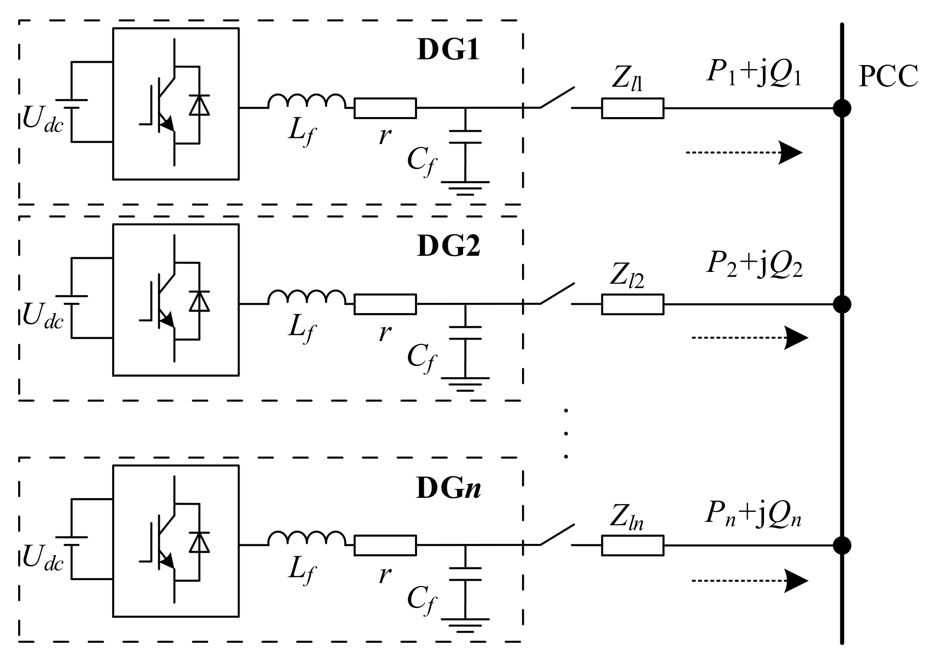
Figure 1 shows a simplified diagram of an islanded microgrid, where n DG units are interfaced to the PCC through different DG feeders. Each DG unit consists of a DC source, an inverter, and an LC filter. r is the equivalent resistance of the filter inductor. is the line impedance from DGi to PCC. Pi + jQi is the power transferred from DGi to PCC. The microgrid also includes several unbalanced and nonlinear loads placed at the PCC.
2.1. Power Sharing
Unbalanced loads will produce negative sequence currents, and nonlinear loads produce harmonic currents. The voltage generated by these current components on the equivalent line impedance causes the system voltage to be unbalanced and the harmonic content is too large, and at the same time affects the power-sharing performance of the parallel inverters.
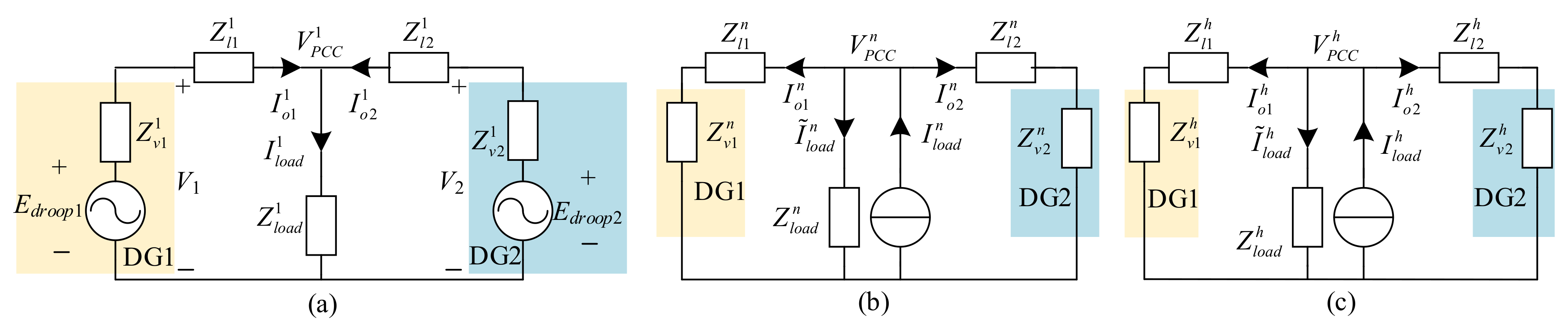
Using virtual impedance to reconstruct the equivalent line impedance at different frequencies and sequences can improve the power-sharing accuracy and PCC power quality. The equivalent circuits under fundamental positive sequence, negative sequence and h-order harmonics are shown in Figure 2.
The superscripts 1, n, and h in Figure 2 represent the variables under the fundamental positive sequence, fundamental negative sequence, and h-order harmonic network, respectively. and are virtual impedance and line impedance, respectively. is the given voltage for traditional active droop control. , and are fundamental positive sequence components, fundamental negative sequence components and h-order harmonic components of inverter output current respectively. Moreover, the load is much larger than the line impedance, where the negative sequence current flowing through the balanced load under the negative sequence network and the harmonic current flowing through the balanced load under the h-order harmonic network can be ignored.
Parallel inverters without communication usually use resistive droop control as follows
where, and are the voltage amplitude and frequency at no-load; , are the active power and reactive power output by the inverter, , are the voltage amplitude and frequency in the corresponding state; , are the droop coefficients of active and reactive, respectively.
The power-sharing of parallel inverters needs to satisfy the following relationship
To achieve power-sharing, the setting of virtual impedance should satisfy
2.2. PCC Voltage Quality Analysis
According to Figure 2a, it can be seen that the PCC fundamental positive sequence voltage is calculated as
It can be known from Equation (4) that when the circuit reaches a steady-state, the PCC voltage is lower than the reference voltage. This is mainly because a part of the voltage drop occurs on the equivalent line impedance, which causes the PCC voltage amplitude to drop. The greater the output current, the greater the voltage drop.
According to Figure 2b,c, the PCC fundamental negative sequence voltage and the h-order harmonic voltage are
According to Equation (5), to reduce the fundamental negative sequence voltage and harmonic voltage of PCC, the virtual impedances should take a negative value.
According to the IEEE 1459-2010 standard [23], the DG harmonic power is calculated as
where is the amplitude of the fundamental positive sequence voltage. is the amplitude of the harmonic current.
The three-phase voltage unbalance of PCC is calculated as
where , and are the effective value of phase voltage, and is the average value of phase voltage.
3. Luenberger Observer for Three-Phase Power Grid
The calculation of the virtual impedance voltage at different frequencies and sequences requires the corresponding inverter output current components. For this reason, a Luenberger observer for the three phase grid current is designed in this paper.
3.1. Three Phase Grid Current Model
The 3P3W system does not contain zero sequence components. The grid current can be divided into the positive and negative sequence components of each harmonic [24], namely
where the subscripts p and n represent positive and negative sequence components respectively.
The positive sequence component and the negative sequence component of the current in the abc coordinate system are
where, and are the amplitudes of h-order harmonic positive and negative sequence current respectively; and are the initial phase angles of positive and negative sequence current, respectively. ω is the grid current angular frequency.
After Clarke transformation, the grid current in the αβ coordinate system can be obtained as
where, and are the positive sequence currents in the αβ coordinate system; and are the negative sequence currents in the αβ coordinate system.
According to (9), the positive sequence current and negative sequence current in the coordinate system αβ are respectively
From Equations (9)–(11), a dynamic equation from the fundamental wave to the m-order harmonics can be established, and the current and its derivative satisfy
where,
For system (14), there are
According to (15), the system (14) is observable.
Similarly, according to (9), (12) and (13), the current and its derivative satisfy the dynamic equation
where,
The system (16) is also observable.
3.2. Luenberger Observer of Three Phase Grid Current and Its Stability Analysis
The Luenberger observer for system (14) is as follows
where the feedback coefficient , “ˆ” means the estimated value of the variable.
Then the h-order harmonic current is estimated as
The 5th and 7th harmonic content in the system is large enough to total current. The designed observer only estimates the fundamental wave, the 5th harmonic and the 7th harmonic. The following stability analysis is performed only for three-phase current Luenberger observers with 5th and 7th harmonics.
In Equation (17), replacing in the first equation with the second equation, the following equation can be obtained
where,
To simplify the analysis, each element in the feedback matrix G is taken as g. Equation (19) is discretized and simplified to
where T is the sampling period, Ae is given in the Appendix A.
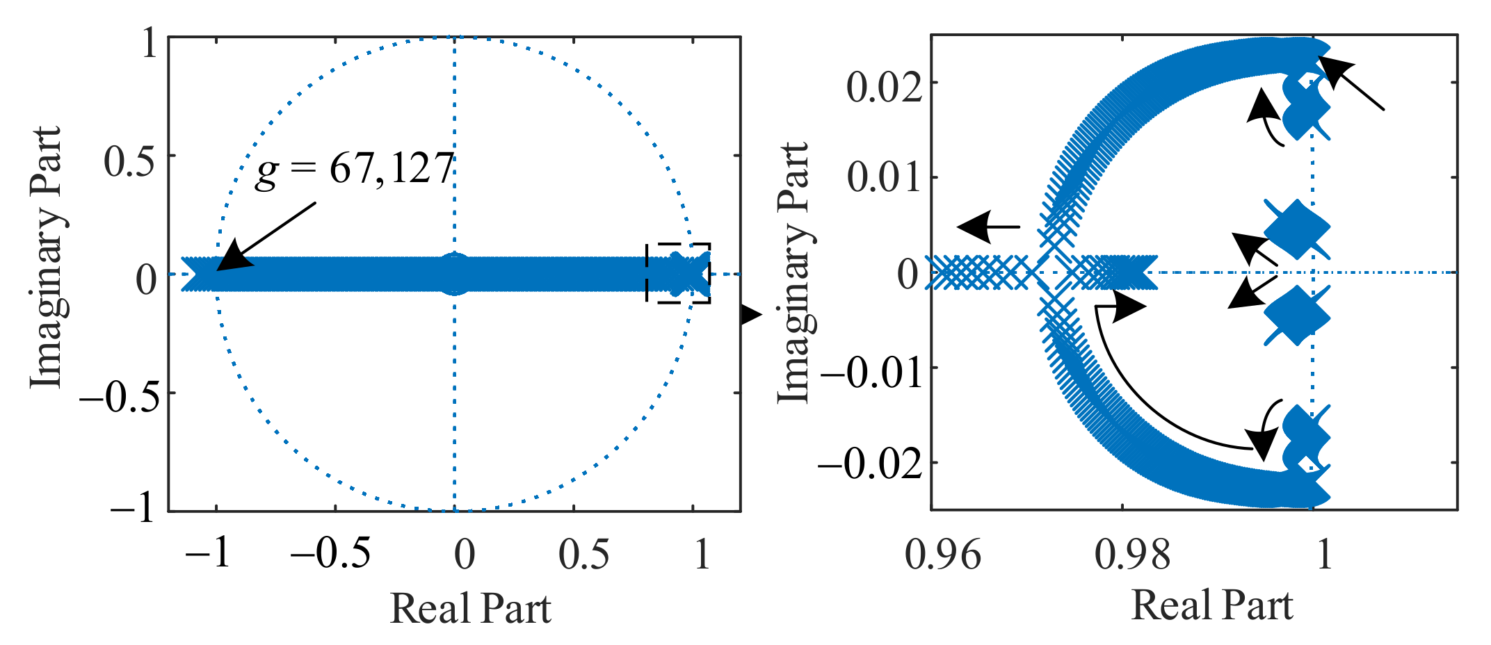
The dynamic response of the Luenberger state observer depends on the eigenvalues of the state equation coefficient matrix Ae. When the eigenvalues of Ae are all distributed within the unit circle of the Z domain, the discrete Luenberger disturbance observer is stable.
Let , . When the feedback coefficient g increases from small, the pole change of the coefficient matrix Ae is shown in Figure 3. It can be concluded from Figure 3 that when 46 < g < 67,127, the modulus value of all eigenvalues of the coefficient matrix Ae is less than 1, so the observer is stable; when g > 67,127 or g < 46, there is one eigenvalue whose modulus value is greater than 1, so the observer is unstable.
4. Proposed Control Strategy
4.1. Basic Idea
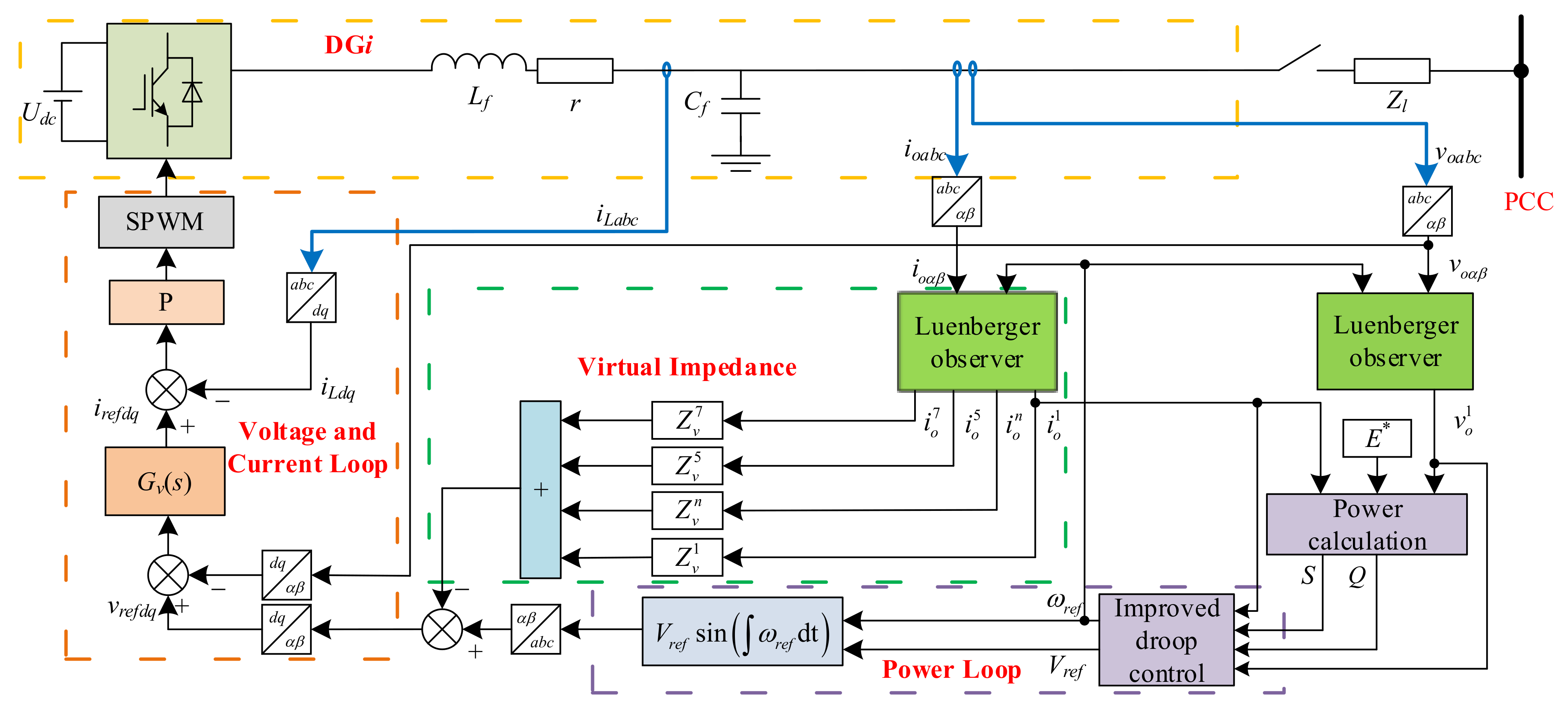
The overall control structure of the inverter is shown in Figure 4. and are the output voltage and current of DGi respectively. is the filter inductor current. and are the reference values of the frequency and voltage amplitude of the improved droop control output respectively.
The positive fundamental sequence component of the current is extracted by the three phase grid Luenberger observer designed in the previous section. The apparent power S calculated from the positive sequence component of the fundamental wave of the output current and the no-load voltage is fed back to the active droop control, which can reduce the output current difference of the inverter. The voltage controller is a parallel connection of PI and quasi-proportional resonance controllers, which realizes the no steady-state error control of fundamental positive sequence, fundamental negative sequence and harmonics. In this paper, the virtual impedance feeds back the currents of different frequencies and sequences, and configures each virtual impedance independently, which not only satisfies the power-sharing condition, but also reduces the equivalent fundamental negative sequence impedance and harmonic impedance.
4.2. Analysis of Virtual Impedance Value Range
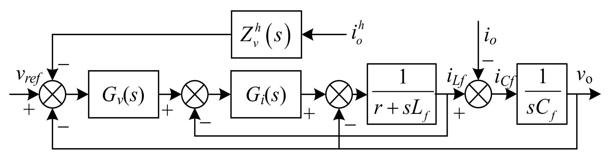
The voltage and current double closed-loop control with h-order virtual harmonic impedance are shown in Figure 5. , and are the filter inductor current, filter capacitor current and inverter output current, respectively. is the inverter output voltage.
In Figure 5, is the proportional controller, is the parallel voltage controller of PI and QPR, which is expressed as
where, and are the proportional coefficients and integral coefficients of the PI controller, respectively; and are the gain of the QPR controller, is the shear frequency, and is the fundamental frequency.
The equivalent harmonic impedance from the inverter to the PCC can be described as
where, .
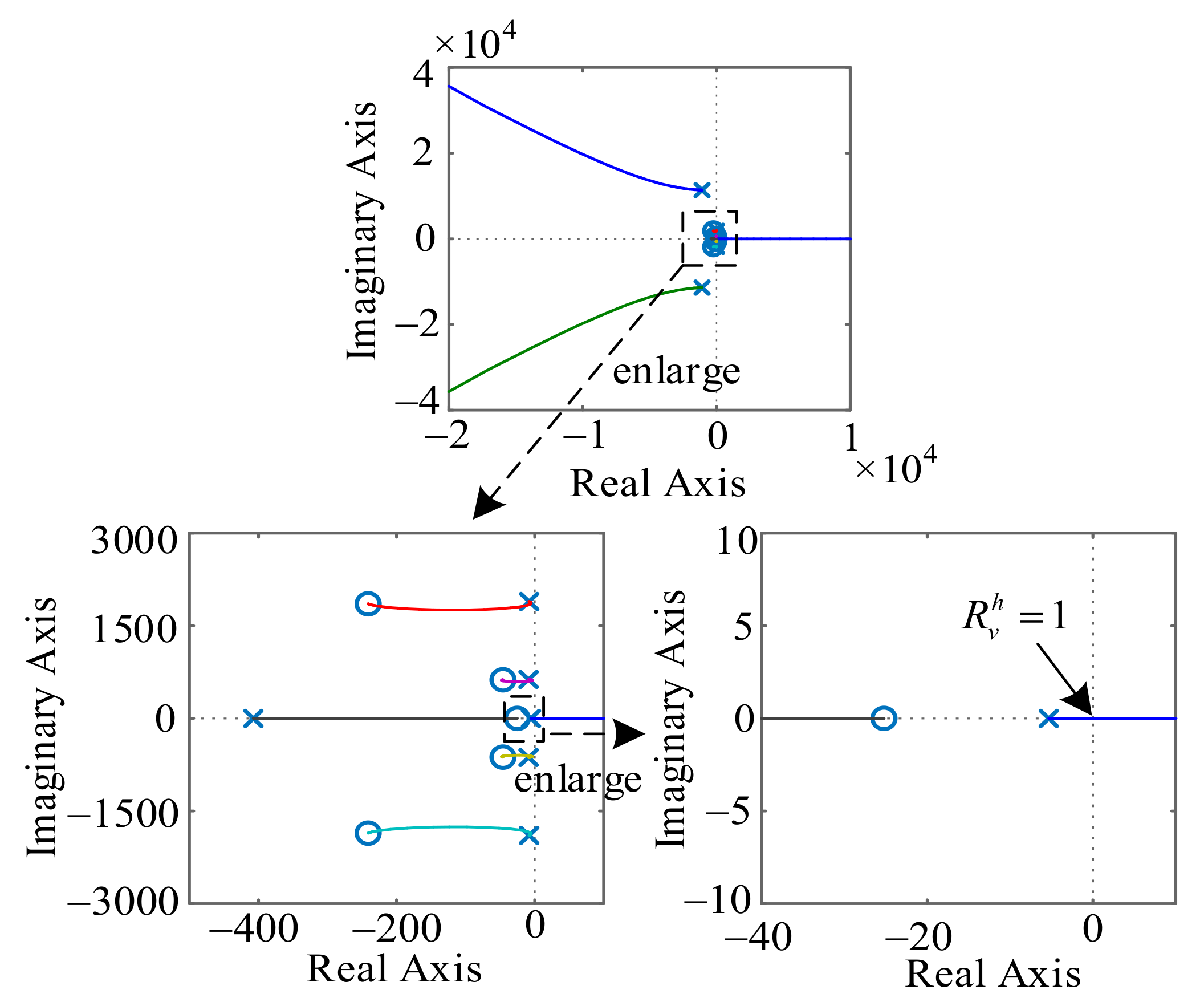
To reduce power coupling, there is . DG1 and the line impedance can be equivalent to impedance under the h-order harmonic. With PCC harmonic voltage as input and as output, is the closed-loop transfer function of the system. Let = 0.8, = 20, = 0.6, = 314, = 6.28, = 5, = 30. The filter parameters are shown in Table 1. The root locus of the system gain can be obtained by substituting the parameters as shown in Figure 6. The root locus equation has been given in the Appendix A.
According to Figure 6, when the system gain is greater than the line resistance Rl1 = 1 Ω, there is a pole in the right half-plane, and the system is unstable. Similarly, the critical value of other virtual resistors in the parallel system should be the corresponding line resistance. To sum up, for the sake of making the system stable, the value of virtual negative resistance should be less than the value of line resistance as far as possible, and the value of virtual inductance should ensure the resistance of the whole system.
4.3. Droop Control with Voltage Compensation
According to Equation (4), it can be known that the PCC voltage is lower than the reference voltage, so this section compensates for the PCC voltage.
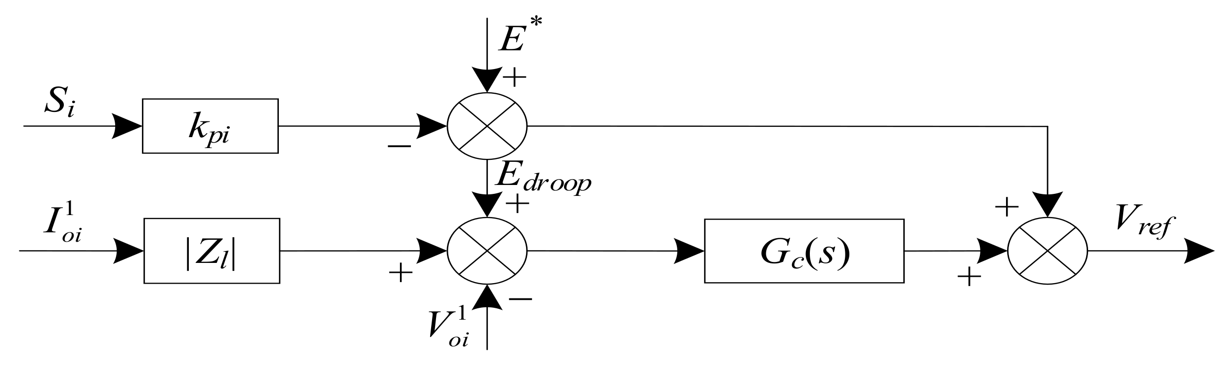
According to Figure 7, the output reference voltage amplitude of the active droop equation is
The output voltage amplitude reference value is
where and are the fundamental amplitudes of the inverter output voltage and current, is the line impedance modulus, and adopt proportional-integral controller ( = + ).
When the system reaches a steady-state, there are
Equation (26) shows that the PCC voltage is equal to the output reference voltage of the traditional active droop controller in the steady-state.
5. Simulation Results
To verify the effectiveness of the proposed control strategy, this paper builds a simulation model based on Matlab/Simulink. In the model, two voltage source three-phase inverters are operated in parallel in islanded mode. The droop control parameters of the two inverters have the same value, and the impedance of the line connected to the PCC in parallel is not equal. The inverter output voltage is a sine wave with a frequency of 50 Hz and a peak value of 311 V. The three phase uncontrolled rectifier module is used as a non-linear load. The low-voltage microgrid line parameters are shown in Table 1.
The simulation parameters of the two control strategies are shown in Table 2 and Table 3, respectively. The common load of PCC connections is shown in Table 4. The simulation results are shown in Figure 7 and Figure 8.
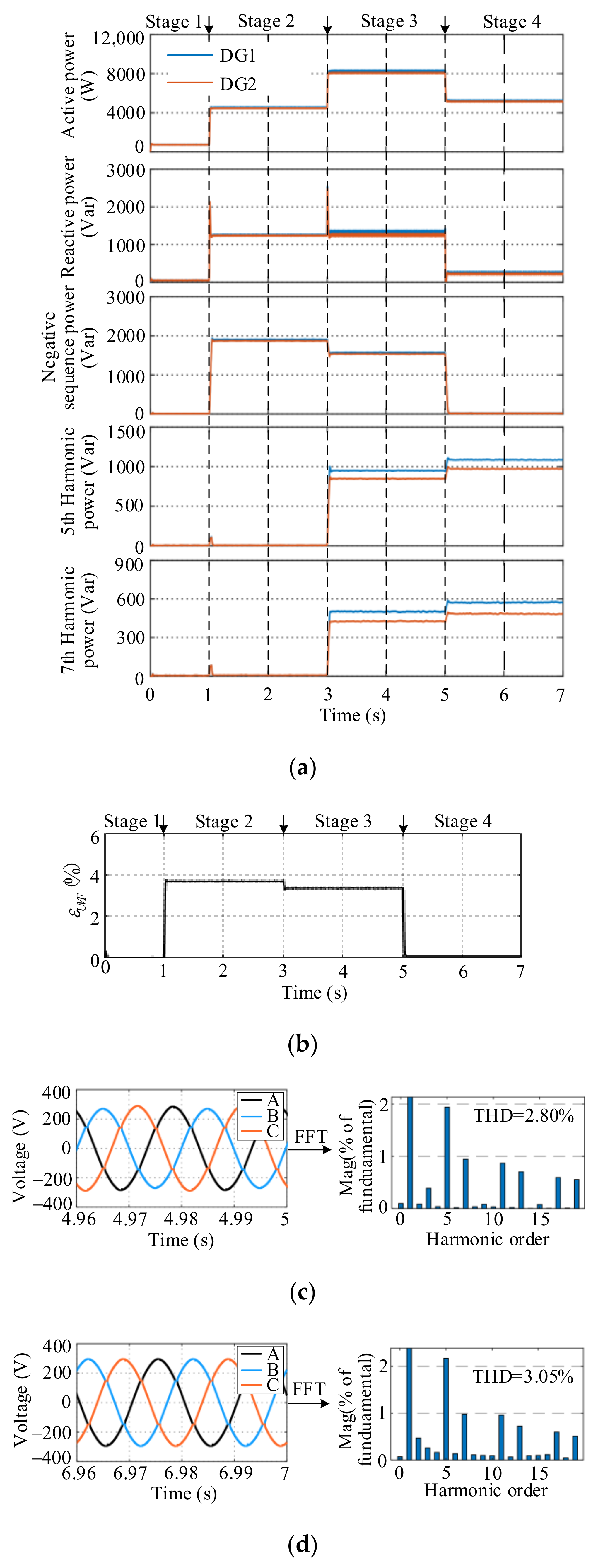
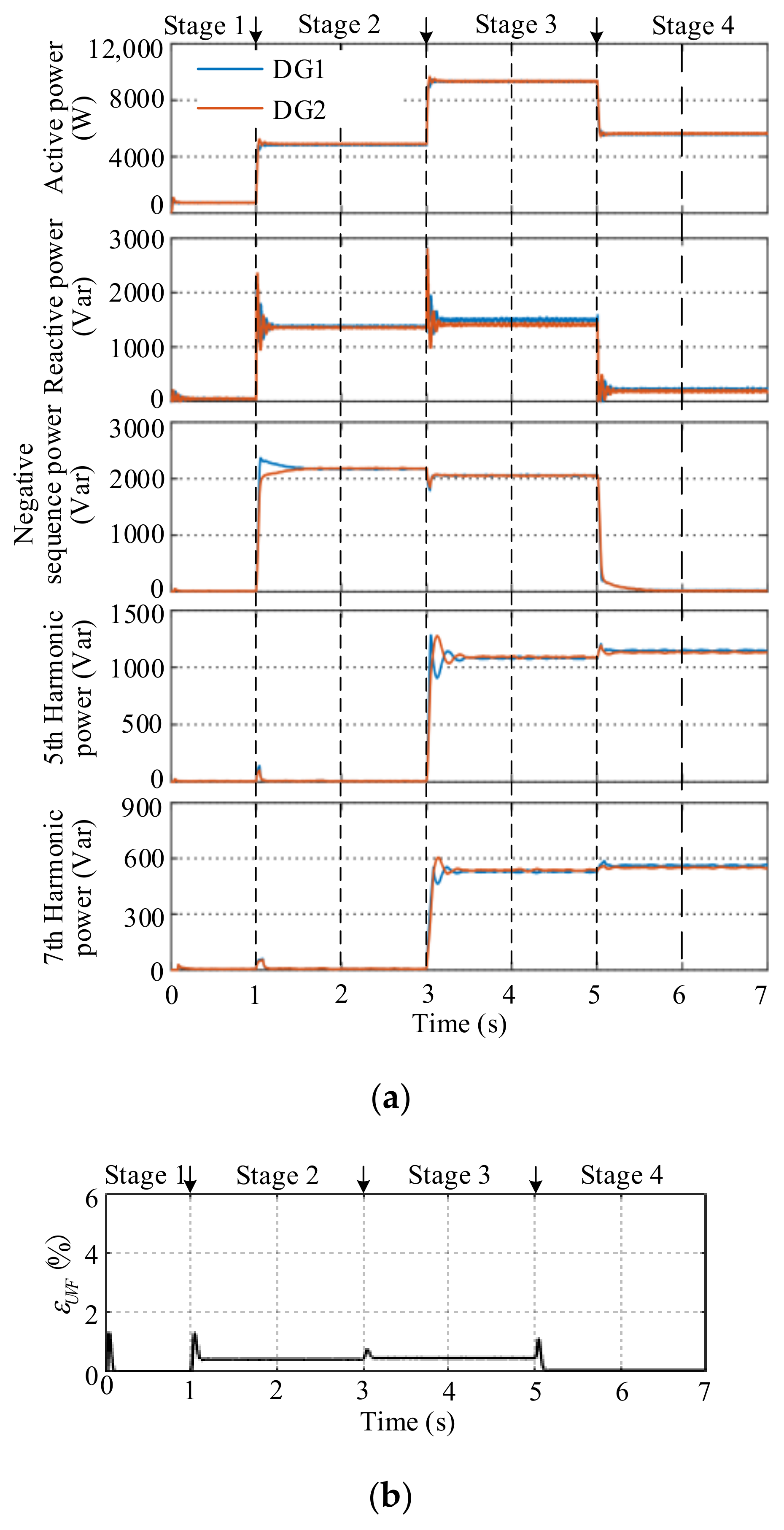
Figure 8a and Figure 9a show the power-sharing performance of comparison, which are the fundamental positive sequence active power, fundamental positive sequence reactive power, fundamental negative sequence power, 5th harmonic power and 7th harmonic power from top to bottom. In stage 1 and stage 2, both strategies achieve power-sharing. When the nonlinear load 3 is connected at 3 s, the harmonic power of the two DGs is not equal in tradition, but in the proposed strategy. It can be seen that in the proposed control strategy, the virtual impedance is used to compensate for the harmonic impedance, so that the harmonic power can also be equally divided.
Figure 8b and Figure 9b shows the three phase voltage unbalance at each stage. In stages 2 and 3, there is an unbalanced load 2 connected to the PCC, the three phase voltage unbalance is 3.7% at stage 2 in tradition, which is 0.4% in the proposed. Due to the reduction of the fundamental negative sequence impedance and the use of parallel voltage controllers of PI and QPR, the three phase voltage unbalance of the PCC is greatly reduced.
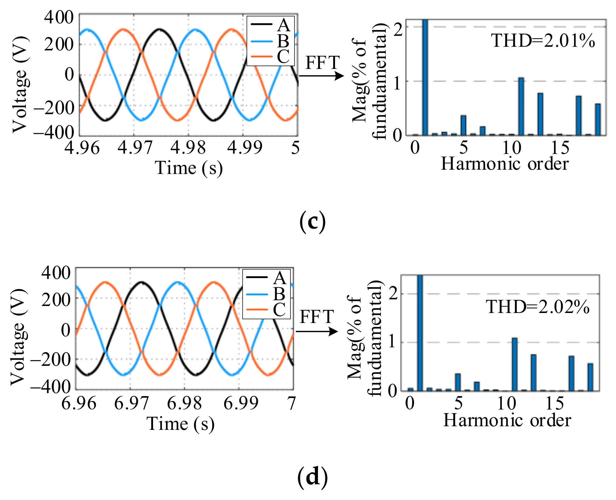
Figure 8c,d and Figure 9c,d show the PCC voltage waveforms and phase A voltage FFT analysis of stages 3 and 4. The PCC voltage is distorted due to the nonlinear load 3 being connected to the PCC in stages 3 and 4. In traditional virtual impedance droop control, the 5th and 7th harmonic components of the PCC voltage are higher. The proposed control strategy reduces the impedance of the 5th and 7th harmonics, and significantly reduces the content of the 5th and 7th harmonics of the PCC voltage.

Table 1.
Line Parameters of Low Voltage Microgrid.
| Parameters | Values | Parameters | Values |
|---|---|---|---|
| 700 V | 0.413 mH | ||
| 5 mH | 2 Ω | ||
| 0.2 Ω | 0.826 mH | ||
| 20 µF | Balance load 1 | 100 Ω + 20 mH | |
| 10 kHz | Unbalance load 2 | Phase A 30 Ω + 30 mH Phase B 0 Ω Phase C 30 Ω + 30 mH | |
| 1 Ω | Non-linear load 3 | 25 Ω |
Table 2.
Simulation Parameters of Traditional Virtual Impedance Droop Control.
| Parameters | Values | Parameters | Values |
|---|---|---|---|
| 1.555 × 10⁻³ | 0 Ω | ||
| 2.5 × 10⁻⁴ | −0.413 mH | ||
| , | 0.8, 50 | −1 Ω | |
| 0.6 | −0.826 mH |
Table 3.
The Simulation Parameters of the Control Strategy Proposed.
| Parameters | Values | Parameters | Values |
|---|---|---|---|
| , | 0.8, 20 | −0.6 Ω, −0.413 mH | |
| 6.28 | −0.6 Ω, −0.413 mH | ||
| , | 0.4, 50 | −1 Ω, −0.826 mH | |
| 260 | −2 Ω, −0.826 mH | ||
| 0 Ω, −0.413 mH | −1.6 Ω, −0.826 mH | ||
| −1 Ω, −0.413 mH | −1.6 Ω, −0.826 mH |
Table 4.
Connected common load.
| Stage1 | Stage2 | Stage3 | Stage4 | |
|---|---|---|---|---|
| time of duration | 0–1 s | 1–3 s | 3–5 s | 5–7 s |
| Common load | load 1 | load 1 and 2 | load 1, 2 and 3 | load 2 and 3 |
6. Experimental Verification
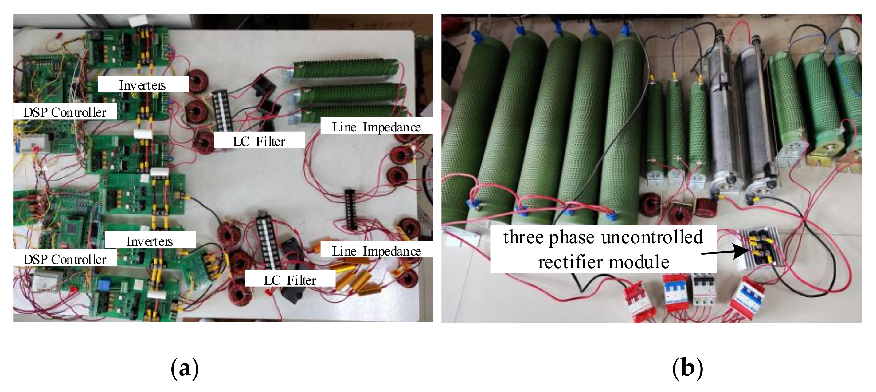
To further verify the effectiveness of the proposed method, a parallel system of two inverters is built with TMS320F28335 as the controller, which is shown in Figure 10. The experimental parameters are shown in Table 5, and the two inverters have the same droop control coefficient.
6.1. PCC Connected to Unbalanced Load
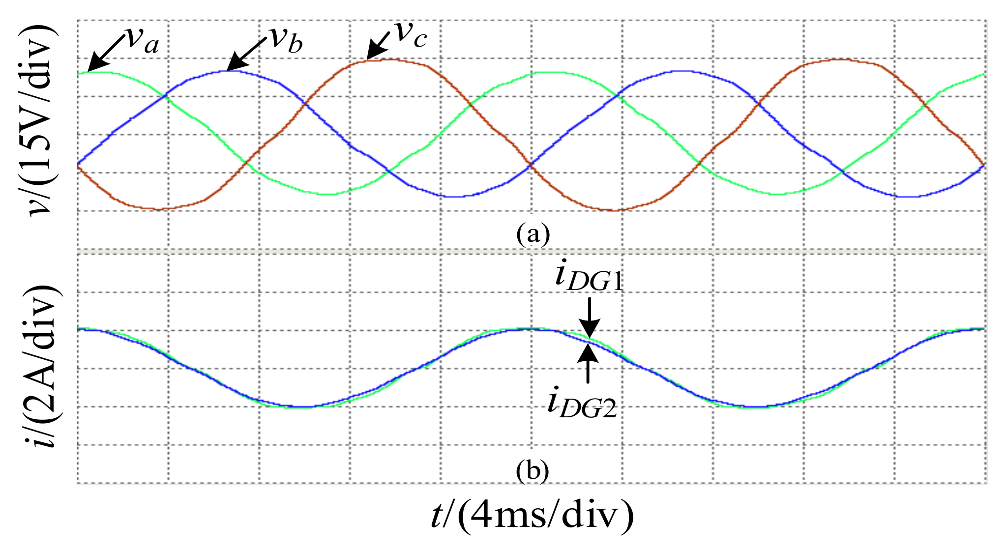
PCC is connected to balanced load 1 and unbalanced load 2. The PCC three phase voltage and DG output current phase A under the two control strategies are shown in Figure 11 and Figure 12.
The DGi output currents under the two control strategies are almost equal. The three phase voltage unbalance is reduced from 14.66% under the traditional control strategy to 1.70% under the proposed control strategy.
6.2. PCC Connected to Non-Linear Load
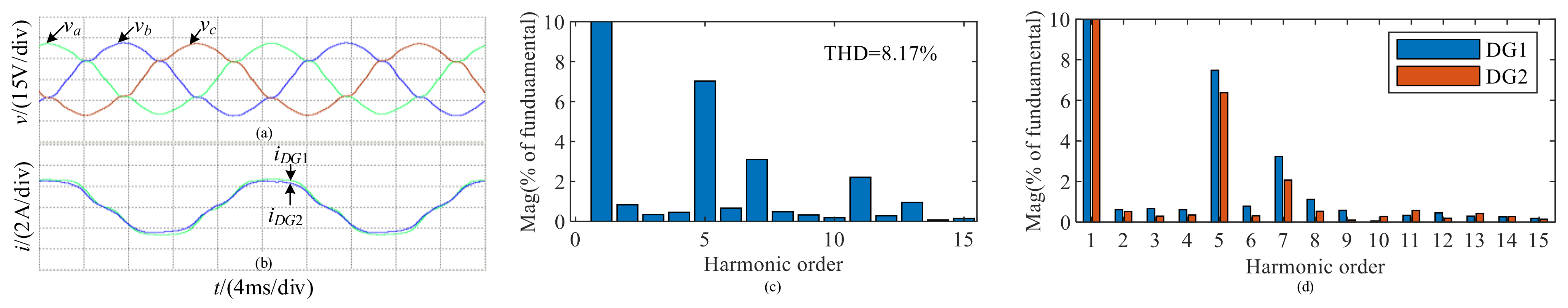
In Figure 13a,b, because the PCC is connected with a balanced load 1 and a non-linear load 3, the PCC voltage is severely distorted, and the FFT analysis of phase A voltage is shown in Figure 13c. THD has reached 8.17%, and the 5th and 7th harmonic content are relatively high. The FFT analysis of DG phase A output current is shown in Figure 13d. Due to the small impedance of the DG1 line, the harmonic content of its output current is relatively high. The experimental results show that the traditional virtual impedance droop control can not realize the equal distribution of harmonic power, and the PCC voltage is severely distorted.
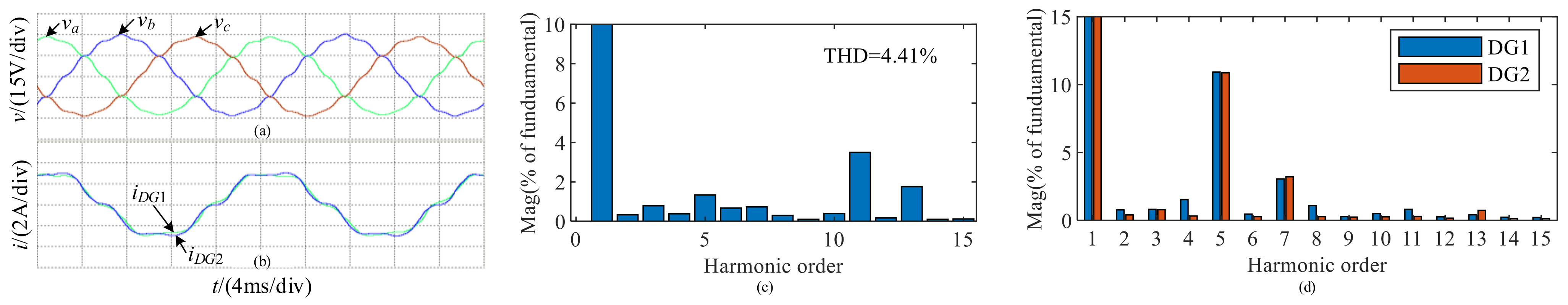
After adopting the control method proposed, the PCC voltage and Phase A output current of DGs are shown in Figure 14a,b. The FFT analysis of the PCC phase A voltage is shown in Figure 14c, the THD is reduced to 4.41%, and the 5th and 7th harmonic content of the control are significantly reduced. The FFT analysis of DG phase A output current is shown in Figure 14d, and the 5th and 7th harmonic content are almost equal. The experimental results show that the method proposed can realize the equal distribution of harmonic power, reduce the PCC voltage THD, and improve the electricity quality. Since the equivalent harmonic impedance is reduced, the voltage harmonic content of the PCC is reduced, and the inverter also gets more harmonic current. But at the same time, the harmonic current of the linear load is reduced. Compared with the traditional virtual impedance control, the harmonic content of the output currents of inverter 1 and inverter 2 under the proposed control strategy is increased. This phenomenon is more pronounced due to the lower experimental voltage level and the smaller impedance of the load.
6.3. PCC Connected to Unbalanced and Non-Linear Mixed Load
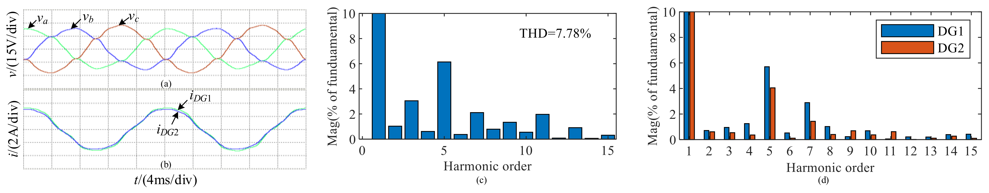
In Figure 15a,b, because the PCC is connected with a balanced load 1, an unbalanced load 2 and a non-linear load 3, the PCC voltage quality is seriously degraded. The three-phase voltage imbalance reached 11.04%. The FFT analysis of the phase A voltage is shown in Figure 15c. THD reaches 7.87%, so part of the harmonic current flows to the balanced load 1. The FFT analysis of DG phase A output current is shown in Figure 15d. The harmonic content of the DG1 output current is relatively high. The experimental results show that the traditional virtual impedance droop control can not realize the equal distribution of harmonic power under the condition of a mixed load, the PCC voltage is severely distorted and the three-phase voltage unbalance is large.
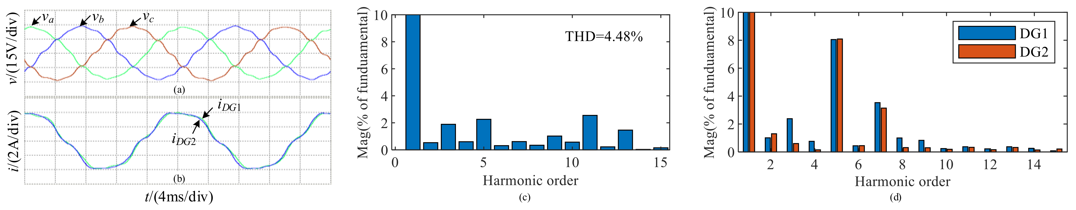
After adopting the control method proposed, the PCC three phase voltage is shown in Figure 16a. Its three phase voltage unbalance has dropped to 1.69%. The FFT analysis of the PCC phase A voltage is shown in Figure 16c. The THD is reduced to 4.48%, and the 5th and 7th harmonic content of the control are significantly reduced. The FFT analysis of DG phase A output current is shown in Figure 16d, and the 5th and 7th harmonic content are almost equal. The experimental results show that the method proposed in this paper can realize the equal distribution of harmonic power under the mixed load, reduce the PCC voltage THD and the three-phase voltage unbalance, and improve the electricity quality.
6.4. Transient Performance of the Proposed Method
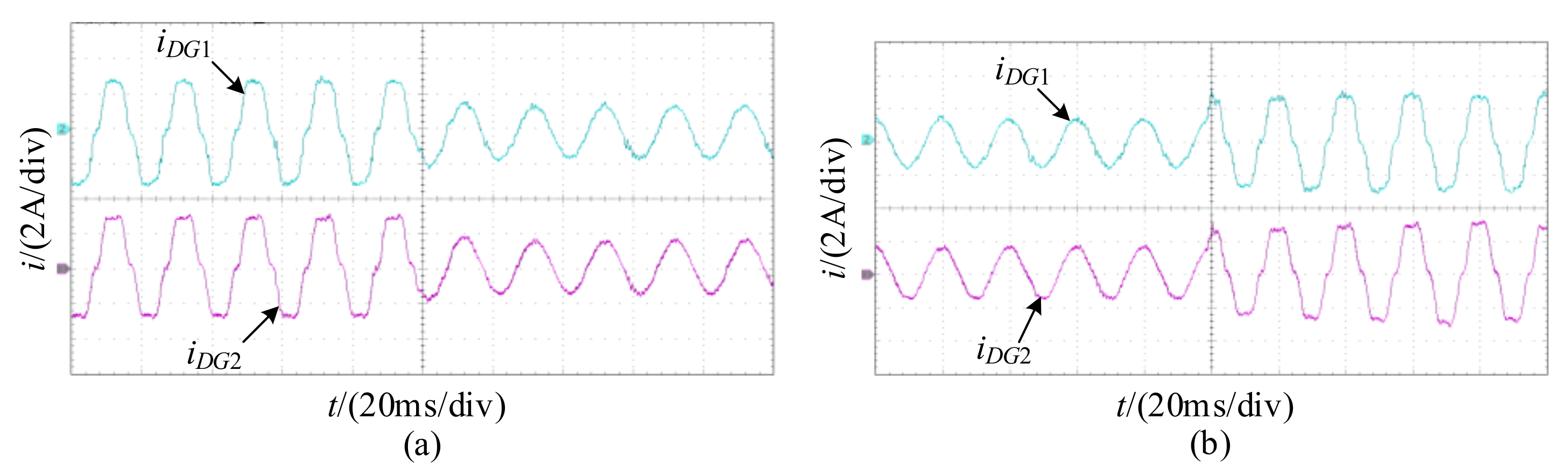
The inverter adopts the proposed control strategy, and the output current of the inverter when the load changes are shown in Figure 17. Figure 17a,b are the experimental waveforms of connecting and disconnecting the nonlinear load 3 when the PCC is connected with the three-phase balanced load 1, respectively. It can be seen that the proposed control strategy has a faster response.
7. Conclusions
To solve the distribution problem of negative sequences and harmonics in microgrids, and the issue of the degradation of PCC voltage quality when the low-voltage microgrid is connected with unbalanced and non-linear loads, a control method based on the Luenberger observer is proposed. The conclusions are as follows:
- (1)
- Analyze the generation mechanism of fundamental negative sequence voltage and harmonic voltage, and it is pointed out that the fundamental negative sequence voltage and harmonic voltage can be reduced based on power-sharing by using virtual impedance with a negative value.
- (2)
- Design a Luenberger observer for three phase current and prove its stability. Use this observer to get the fundamental positive sequence, fundamental negative sequence and harmonic components. Configure each sequence of virtual impedances to achieve power-sharing and improve electricity quality. And analyzed the value range of virtual impedance.
- (3)
- Design the active power droop equation with voltage compensation to increase the voltage amplitude.
Author Contributions
Methodology, Y.C.; Software, C.L. All authors have read and agreed to the published version of the manuscript.
Funding
This work was supported by the Science and Technology Department Industrial Public Relations of Shaanxi Province (No. 2016GY-064).
Institutional Review Board Statement
Not applicable.
Informed Consent Statement
Not applicable.
Data Availability Statement
Not applicable.
Conflicts of Interest
The authors declare no conflict of interest.
Appendix A
Root locus equation:
where,
| a5 = −0.48 | a4 = −287.8 | a3 = −1.9 × 10⁶ | a2 = −2.94 × 10⁸ |
| a1 = −6.72 × 10¹¹ | a0 = −1.68 × 10¹³ | A8 = 4.13 × 10⁻¹¹ | A7 = 1.08 × 10⁻⁷ |
| A6 = 5.6 × 10⁻³ | A5 = 2.84 | A4 = 2.18 × 10⁴ | A3 = 9.41 × 10⁶ |
| A2 = 7.98 × 10⁹ | A1 = 3.19 × 10¹² | A0 = 1.68 × 10¹³ |
References
- Kohn, W.; Zabinsky, Z.B.; Nerode, A. A Micro-Grid Distributed Intelligent Control and Management System. IEEE Trans. Smart Grid 2015, 6, 2964–2974. [Google Scholar] [CrossRef]
- Nasser, N.; Fazeli, M. Buffered-Microgrid Structure for Future Power Networks; a Seamless Microgrid Control. IEEE Trans. Smart Grid 2021, 12, 131–140. [Google Scholar] [CrossRef]
- Lee, K.; Yun, S.; Hwang, P.; Seo, D.; Pak, Y. Demonstration project of distribution level microgrid in Penetanguishene of Canada. In Proceedings of the CIRED Workshop 2016, Helsinki, Finland, 14–15 June 2016; pp. 1–3. [Google Scholar]
- Cho, J.; Kim, H.; Cho, Y.; Kim, H.; Kim, J. Demonstration of a DC Microgrid with Central Operation Strategies on an Island. In Proceedings of the 2019 IEEE Third International Conference on DC Microgrids (ICDCM), Matsue, Japan, 20–23 May 2019; pp. 1–5. [Google Scholar]
- Nishita, Y.; Izui, Y.; Honda, M.; Mizuochi, M.; Natsuume, D.; Tabata, H. DC Microgrid Experimental System at KIT and its Autonomous Distributed DC Voltage Control Method. In Proceedings of the 2021 IEEE Fourth International Conference on DC Microgrids (ICDCM), Arlington, VA, USA, 18–21 July 2021; pp. 1–6. [Google Scholar]
- Fujimoto, S.; Obara, S. Electricity Quality Analysis of Teuri-Yagishiri Island Microgrid. In Proceedings of the 2019 IEEE 10th International Symposium on Power Electronics for Distributed Generation Systems (PEDG), Xi’an, China, 3–6 June 2019; pp. 353–358. [Google Scholar]
- Ul Hassan, S.; ul Abideen, Z.; Izhar, T. Advanced control techniques for micro-grids power quality improvement. In Proceedings of the 2017 Asian Conference on Energy, Power and Transportation Electrification (ACEPT), Singapore, 24–26 October 2017; pp. 1–6. [Google Scholar]
- De Brabandere, K.; Bolsens, B.; van den Keybus, J.; Woyte, A.; Driesen, J.; Belmans, R. A Voltage and Frequency Droop Control Method for Parallel Inverters. IEEE Trans. Power Electron. 2007, 22, 1107–1115. [Google Scholar] [CrossRef]
- Zhao, J.; Li, J.; Nian, H.; Yang, L.; Gai, B.; Pan, Z.; Xu, Y. A Feeder Impedance Identification Based Droop Control Method for Accurate Reactive Power Sharing in Islanded Microgrids. In Proceedings of the 2019 10th International Conference on Power Electronics and ECCE Asia (ICPE 2019—ECCE Asia), Busan, Korea, 27–30 May 2019; pp. 1–5. [Google Scholar]
- Han, Y.; Li, H.; Shen, P.; Coelho, E.A.A.; Guerrero, J.M. Review of Active and Reactive Power Sharing Strategies in Hierarchical Controlled Microgrids. IEEE Trans. Power Electron. 2017, 32, 2427–2451. [Google Scholar] [CrossRef] [Green Version]
- Guerrero, J.M.; De Vicuna, L.G.; Matas, J.; Castilla, M.; Miret, J. Output impedance design of parallel-connected UPS inverters with wireless load-sharing control. IEEE Trans. Ind. Electron. 2005, 52, 1126–1135. [Google Scholar] [CrossRef]
- Alcala, J.M.; Castilla, M.; De Vicuña, L.G.; Miret, J.; Vasquez, J.C. Virtual impedance loop for droop-controlled single-phase parallel inverters using a second-order general-integrator scheme. IEEE Trans. Power Electron. 2010, 25, 2993–3002. [Google Scholar] [CrossRef]
- Wai, R.; Zhang, Q.; Wang, Y. A Novel Voltage Stabilization and Power Sharing Control Method Based on Virtual Complex Impedance for an Off-Grid Microgrid. IEEE Trans. Power Electron. 2019, 34, 1863–1880. [Google Scholar] [CrossRef]
- Micallef, A.; Apap, M.; Spiteri-Staines, C.; Guerrero, J.M. Mitigation of Harmonics in Grid-Connected and Islanded Microgrids Via Virtual Admittances and Impedances. IEEE Trans. Smart Grid 2017, 8, 651–661. [Google Scholar] [CrossRef] [Green Version]
- Liu, B.; Liu, Z.; Liu, J.; An, R.; Zheng, H.; Shi, Y. An Adaptive Virtual Impedance Control Scheme Based on Small-AC-Signal Injection for Unbalanced and Harmonic Power Sharing in Islanded Microgrids. IEEE Trans. Power Electron. 2019, 34, 12333–12355. [Google Scholar] [CrossRef]
- He, J.; Li, Y.W.; Guerrero, J.M.; Blaabjerg, F.; Vasquez, J.C. An islanding microgrid power sharing approach using enhanced virtual impedance control scheme. IEEE Trans. Power Electron. 2013, 28, 5272–5282. [Google Scholar] [CrossRef]
- Razi, R.; Iman-Eini, H.; Hamzeh, M. An Impedance-Power Droop Method for Accurate Power Sharing in Islanded Resistive Microgrids. IEEE J. Emerg. Sel. Top. Power Electron. 2020, 8, 3763–3771. [Google Scholar] [CrossRef]
- Hoang, T.V.; Lee, H.-H. Virtual Impedance Control Scheme to Compensate for Voltage Harmonics with Accurate Harmonic Power Sharing in Islanded Microgrids. IEEE J. Emerg. Sel. Top. Power Electron. 2021, 9, 1682–1695. [Google Scholar] [CrossRef]
- He, J.; Li, Y.W.; Blaabjerg, F. An Enhanced Islanding Microgrid Reactive Power, Imbalance Power, and Harmonic Power Sharing Scheme. IEEE Trans. Power Electron. 2015, 30, 3389–3401. [Google Scholar] [CrossRef]
- Moussa, H.; Shahin, A.; Martin, J.; Nahid-Mobarakeh, B.; Pierfederici, S.; Moubayed, N. Harmonic Power Sharing with Voltage Distortion Compensation of Droop Controlled Islanded Microgrids. IEEE Trans. Smart Grid 2018, 9, 5335–5347. [Google Scholar] [CrossRef]
- Liang, X.; Andalib-Bin-Karim, C.; Li, W.; Mitolo, M.; Shabbir, M.N.S.K. Adaptive Virtual Impedance-Based Reactive Power Sharing in Virtual Synchronous Generator Controlled Microgrids. IEEE Trans. Ind. Appl. 2021, 57, 46–60. [Google Scholar] [CrossRef]
- An, R.; Liu, Z.; Liu, J. Successive-Approximation-Based Virtual Impedance Tuning Method for Accurate Reactive Power Sharing in Islanded Microgrids. IEEE Trans. Power Electron. 2021, 36, 87–102. [Google Scholar] [CrossRef]
- IEEE Std 1459–2010 (Revision of IEEE Std 1459–2000); IEEE Standard Definitions for the Measurement of Electric Power Quantities Under Sinusoidal, Nonsinusoidal, Balanced, or Unbalanced Conditions. IEEE: New York, NY, USA, 2010; pp. 1–50.
- Dai, Z.; Lin, W. Adaptive Estimation of Three-Phase Grid Voltage Parameters under Unbalanced Faults and Harmonic Disturbances. IEEE Trans. Power Electron. 2017, 32, 5613–5627. [Google Scholar] [CrossRef]
Figure 1.
Configuration of the islanded microgrid.

Figure 2.
Equivalent circuits of a microgrid at different frequencies and sequences: (a) Equivalent circuit at fundamental positive sequence; (b) Equivalent circuit at fundamental negative sequence; (c) Equivalent circuit at harmonic frequencies.
Figure 2.
Equivalent circuits of a microgrid at different frequencies and sequences: (a) Equivalent circuit at fundamental positive sequence; (b) Equivalent circuit at fundamental negative sequence; (c) Equivalent circuit at harmonic frequencies.

Figure 3.
Pole distribution diagram of Ae when g changes.

Figure 4.
Control system structure block diagram.

Figure 5.
Voltage and current double closed-loop control with h-order virtual harmonic impedance.

Figure 6.
Root locus of system.

Figure 7.
Improved active droop control block diagram.

Figure 8.
Traditional virtual impedance droop control: (a) power-sharing performance; (b) PCC three-phase voltage unbalance ; (c) PCC voltage and A-phase voltage FFT analysis in stage 3; (d) PCC voltage and A-phase voltage FFT analysis in stage 4.
Figure 8.
Traditional virtual impedance droop control: (a) power-sharing performance; (b) PCC three-phase voltage unbalance ; (c) PCC voltage and A-phase voltage FFT analysis in stage 3; (d) PCC voltage and A-phase voltage FFT analysis in stage 4.

Figure 9.
The proposed control strategy: (a) power-sharing performance; (b) PCC three-phase voltage unbalance ; (c) PCC voltage and A-phase voltage FFT analysis in stage 3; (d) PCC voltage and A-phase voltage FFT analysis in stage 4.
Figure 9.
The proposed control strategy: (a) power-sharing performance; (b) PCC three-phase voltage unbalance ; (c) PCC voltage and A-phase voltage FFT analysis in stage 3; (d) PCC voltage and A-phase voltage FFT analysis in stage 4.


Figure 10.
Experimental hardware: (a) Parallel inverters; (b) loads.

Figure 11.
The experimental results of the traditional control method under the unbalanced load connected to the PCC: (a) PCC voltage; (b) Phase A output current of DGs.
Figure 11.
The experimental results of the traditional control method under the unbalanced load connected to the PCC: (a) PCC voltage; (b) Phase A output current of DGs.

Figure 12.
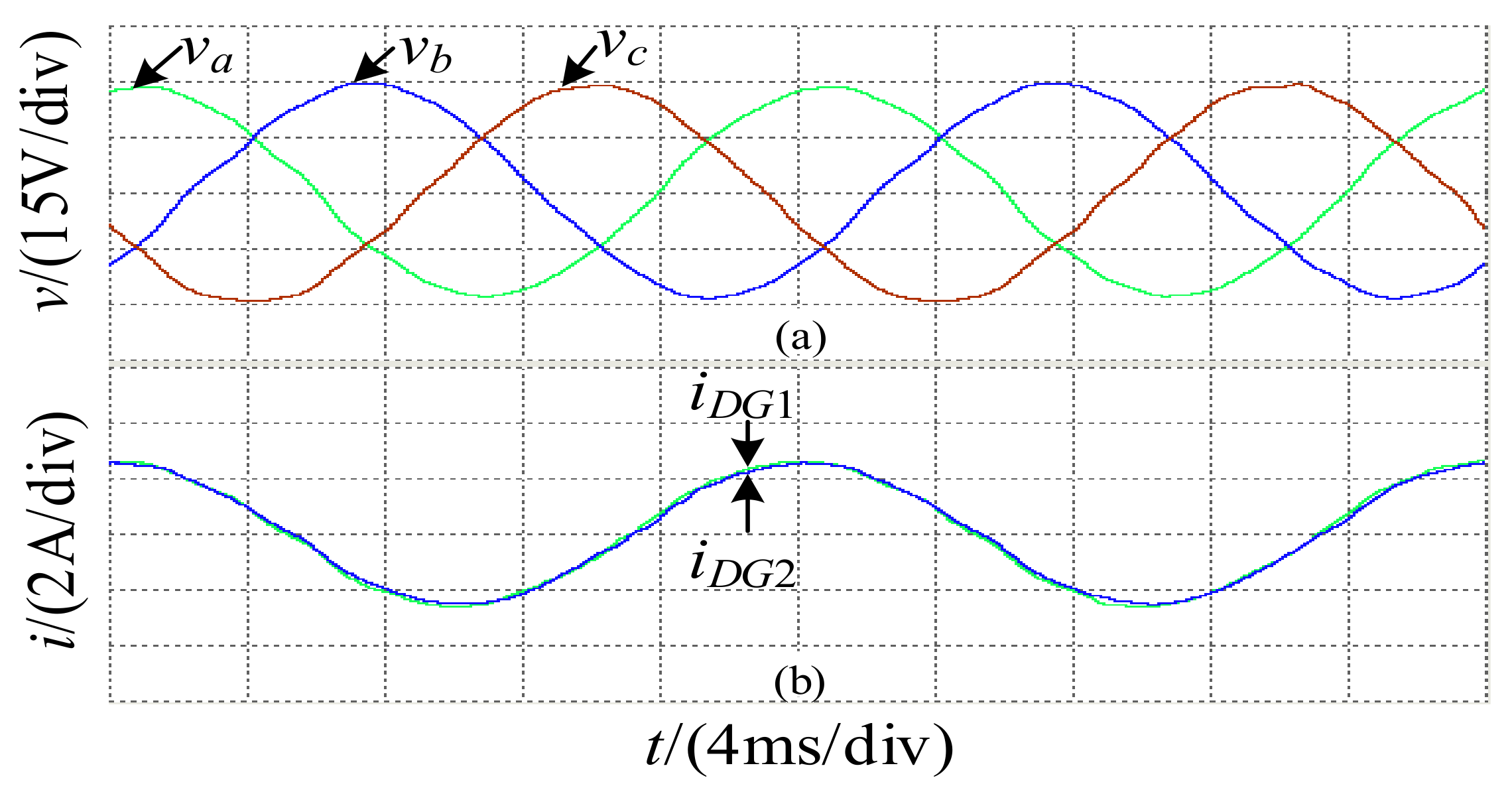
The experimental results of the method proposed under unbalanced load connected to PCC: (a) PCC voltage; (b) Phase A output current of DGs.
Figure 12.
The experimental results of the method proposed under unbalanced load connected to PCC: (a) PCC voltage; (b) Phase A output current of DGs.

Figure 13.
The experimental results of the traditional control method under the non-linear load connected to the PCC: (a) PCC voltage; (b) Phase A output current of DGs; (c) FFT analysis of phase A voltage of PCC; (d) FFT analysis of phase A output current of DGs.
Figure 13.
The experimental results of the traditional control method under the non-linear load connected to the PCC: (a) PCC voltage; (b) Phase A output current of DGs; (c) FFT analysis of phase A voltage of PCC; (d) FFT analysis of phase A output current of DGs.

Figure 14.
The experimental results of the method proposed under the non-linear load connected to the PCC: (a) PCC voltage; (b) Phase A output current of DGs; (c) FFT analysis of phase A voltage of PCC; (d) FFT analysis of phase A output current of DGs.
Figure 14.
The experimental results of the method proposed under the non-linear load connected to the PCC: (a) PCC voltage; (b) Phase A output current of DGs; (c) FFT analysis of phase A voltage of PCC; (d) FFT analysis of phase A output current of DGs.

Figure 15.
The experimental results of the traditional control method under the mixed load connected to the PCC: (a) PCC voltage; (b) Phase A output current of DGs; (c) FFT analysis of phase A voltage of PCC; (d) FFT analysis of phase A output current of DGs.
Figure 15.
The experimental results of the traditional control method under the mixed load connected to the PCC: (a) PCC voltage; (b) Phase A output current of DGs; (c) FFT analysis of phase A voltage of PCC; (d) FFT analysis of phase A output current of DGs.

Figure 16.
The experimental results of the method proposed under the mixed load connected to the PCC: (a) PCC voltage; (b) Phase A output current of DGs; (c) FFT analysis of phase A voltage of PCC; (d) FFT analysis of phase A output current of DGs.
Figure 16.
The experimental results of the method proposed under the mixed load connected to the PCC: (a) PCC voltage; (b) Phase A output current of DGs; (c) FFT analysis of phase A voltage of PCC; (d) FFT analysis of phase A output current of DGs.

Figure 17.
Experimental results of the proposed method under load changing conditions: (a) nonlinear load access to PCC and (b) nonlinear loads disconnected from PCC.
Figure 17.
Experimental results of the proposed method under load changing conditions: (a) nonlinear load access to PCC and (b) nonlinear loads disconnected from PCC.

Table 5.
Experiment parameters.
| Parameters | Values | Parameters | Values |
|---|---|---|---|
| 90 V | 0.5 Ω | ||
| 5 mH | 1 mH | ||
| 0.2 Ω | 1.5 Ω | ||
| 20 µF | 2 mH | ||
| 20 kHz | Balance load 1 | 10 Ω | |
| 30 V | Unbalance load between phase AB 2 | 20 Ω | |
| 50 Hz | non-linear load 3 | 15 Ω |
Publisher’s Note: MDPI stays neutral with regard to jurisdictional claims in published maps and institutional affiliations. |
© 2022 by the authors. Licensee MDPI, Basel, Switzerland. This article is an open access article distributed under the terms and conditions of the Creative Commons Attribution (CC BY) license (https://creativecommons.org/licenses/by/4.0/).
Share and Cite
MDPI and ACS Style
Cheng, Y.; Li, C. Luenberger Observer-Based Microgrid Control Strategy for Mixed Load Conditions. Energies 2022, 15, 3655. https://0-doi-org.brum.beds.ac.uk/10.3390/en15103655
AMA Style
Cheng Y, Li C. Luenberger Observer-Based Microgrid Control Strategy for Mixed Load Conditions. Energies. 2022; 15(10):3655. https://0-doi-org.brum.beds.ac.uk/10.3390/en15103655
Chicago/Turabian StyleCheng, Yong, and Cong Li. 2022. "Luenberger Observer-Based Microgrid Control Strategy for Mixed Load Conditions" Energies 15, no. 10: 3655. https://0-doi-org.brum.beds.ac.uk/10.3390/en15103655
Note that from the first issue of 2016, this journal uses article numbers instead of page numbers. See further details here.