2. An Overview of the Electrolyzer State of the Art
Work on the material and technological improvement of water electrolysis began at Forschungszentrum Jülich in the early 1980s. Initially, the focus was on increasing the efficiency of alkaline electrolysis through new, innovative approaches to cell composition and structure. As a result of the high foreseeable demand for highly efficient electrolyzers, research work at Jülich was subsequently expanded to include PEM electrolysis technology.
The decomposition of water, or water-splitting, by means of electrolysis involves two partial reactions separated by an ion-conducting electrolyte. Three technically-relevant water electrolysis processes result from the species of ion being used:
High-temperature electrolysis with a solid oxide as an electrolyte;
Alkaline electrolysis with a liquid alkaline electrolyte;
“Acidic” PEM electrolysis with a proton-conducting solid-state polymer electrolyte.
At present, reversible high-temperature electrolysis is only being pursued to a limited extent due to the ceramic materials used in research and industry, and there are currently very few commercial products with a performance range relevant to the energy industry. An experiment involving high-temperature electrolysis in the kW range is being conducted using the network of facilities at Forschungszentrum Jülich, which are described in further detail below [
8]. However, as this article focuses on MW application, the technology itself is not described any further.
Low-temperature electrolysis processes based on alkaline and PEM technologies can be used to establish large, powerful systems (1–100 MW) [
9]. In contrast to PEM electrolysis, a number of alkaline electrolysis designs have been used for several decades at various scales. Their operating temperature is typically around 80 °C and systems of up to 750 Nm
3H2/h are available. These systems use an aqueous solution of potassium hydroxide (KOH) as an electrolyte with a typical concentration of 20–40% and achieve current densities of 0.25–0.45 A/cm
2. Rectangular and circular electrodes and cells with an active area of up to approximately 3 m
2 have also been used. The plant engineering firm Lurgi manufactures pressurized electrolyzers that supply hydrogen and oxygen below 30 bar. Lurgi’s pressurized electrolyzer produces 760 Nm
3/h of hydrogen, which corresponds to an electrical output of approximately 3.6 MW [
10]. Lifetimes of up to 90,000 h are achieved by the stack, with the electrodes and diaphragms needing to be replaced after this period. According to the NOW study by the Fraunhofer Institute for Solar Energy Systems (ISE, Freiburg), the voltage efficiency of the stack amounts to 62–82% in relation to the higher heating value (HHV) [
11]. At less than 20%, the lower partial load operation is especially critical for its flexible application in combination with renewable energy sources. This is a result of the diaphragms that are used, which facilitate the mixture of hydrogen and oxygen due to diffusion, which in turn leads to safety-related switch offs. Another disadvantage of alkaline electrolyzers as compared with PEM electrolysis is the costly gas treatment of the product gases, for which expensive noble metals must be used.
In contrast to alkaline water electrolysis, PEM electrolysis with proton-conducting membranes uses platinum group metals for the electrodes. Due to the use of dense membranes as an electrolyte and the possibility of integration with recombination catalysts, the systems can be operated at 0–100% power; however, in technical facilities the lower threshold is limited to approximately 5% of nominal power due to the internal consumption of peripheral components [
10].
In particular, the high overvoltage at the oxygen electrode is a challenge for the development of materials and is partially responsible for the energy loss of the systems. Studies have shown that RuO
2 and IrO
2 are especially suitable catalysts for oxygen electrodes [
12,
13,
14]. These metal oxides exhibit a high level of activity, adequate long-term stability, and low performance losses [
15,
16,
17,
18,
19,
20,
21,
22,
23,
24]. For this reason, IrO
2 is often used as an anode catalyst for PEM electrolyzers [
25]. Despite its low specific activity compared to RuO
2, IrO
2 is especially suitable due to its low overvoltages [
22,
26] and excellent electrochemical stability compared to RuO
2 [
22].
In current commercial systems, approximately 2 mg/cm
2 iridium is required for the anode and approximately 1 mg/cm
2 of platinum is required for the cathode. At the given operating conditions, these systems run at voltages of about 2 V, current densities of approximately 2 A/cm
2, and operating pressures of up to 30 bar [
27]. This is equivalent to the voltage efficiency of alkaline electrolysis (approximately 67–82%), but with much higher current densities (0.6–2.0 A/cm
2) [
28].
Other studies have investigated the level of iridium loading that is advantageous for function and stability, and identified 1–2 mg/cm
2 as the ideal range [
29]. However, other studies have investigated much lower iridium loading and found that this also results in reasonable operating times [
30]. When using noble metals which are limited in terms of availability, this automatically raises the question as to whether they will be available in sufficient quantities. In [
31], it was investigated whether the extraction of iridium could sufficiently cover demand for the increasing expansion of PEM electrolysis. It was found that noble metal loading would need to be significantly reduced in the next 15 years to ensure a sufficient supply of noble metals. The target loading should reach 50 mg/kW in 2035. Based on a power density of 6 W/cm
2, this corresponds to a catalyst loading of 0.3 mg/cm
2. However, it was found that recycling of the catalyst is an essential prerequisite for this. Carmo et al. describe how this can be implemented in a simple and environmentally-friendly manner, despite the use of solvents [
32].
All large PEM electrolysis manufacturers are working on the development of MW systems with various stack concepts. Hydrogenics, for instance, recently developed and built a 1 MW PEM electrolyzer with a single stack and a nominal power of 1 MW [
33]. For the most part, the commercially-available stacks only operate with current densities < 2.0 A/cm
2. In these systems, approximately 6 mg/cm
2 of iridium or ruthenium is required for the anode, and approximately 2 mg/cm
2 of platinum is required for the cathode [
34]. In contrast to alkaline electrolysis, the lifetime of PEM electrolysis stacks is estimated at <20,000 h. However, Proton Onsite has already achieved a lifetime of more than 50,000 h for stacks used in the PEM electrolyzers of the HOGEN C series [
35].
In terms of thermodynamic considerations, the hydrogen-producing electrode should ideally be operated under pressure [
36]; the oxygen-producing electrode can be operated under atmospheric conditions, as the oxygen being produced is not typically stored under pressure. Tjarks et al. [
37] showed that an electrolyzer operating pressure of up to 20 bar can improve the system’s efficiency.
One of the technical limitations of this differential pressure operation is the mechanical stability of the membrane electrode assembly (MEA) and the sintered body. In addition, the design of modern stacks must account for the fact that in the future, thinner membranes will be used that significantly increase the hydrogen production of an electrolyzer. The influence of membrane thickness on cell performance has been simulated many times and analyzed in the literature [
36,
38,
39,
40]. Stähler et al. [
41] were able to achieve current densities of 11 A/cm
2 at 2 V in a single cell with a membrane thickness of approximately 20 µm. If the membrane thickness is reduced, H
2 permeation through the membrane and the mechanical stress of the membrane, particularly during pressure operation, must be taken into account [
36,
39].
Another important aspect is the adjustment of compression and contact pressure for the porous transport layers (PTLs) being used. Stähler et al. [
42] showed that by increasing compression, the performance of the electrolysis cell can be enhanced, although excess compression of the gas diffusion layers (GDLs) leads to an increase in hydrogen permeation through the membrane. When designing the stack, it is important to avoid increased compressive and shear stresses [
43]. Borgardt et al. conducted analyses on membrane and stack component mechanics in terms of their relation to contact pressure, efficiency, and creep behavior [
44,
45].
In addition to the noble metals required for the electrodes, another challenge of system development is posed by titanium-based separator plates and current collectors, to which coatings must be applied due to hydrogen embrittlement, the formation of oxide layers, and the associated increase in contact resistance. According to publications by Ayers et al. (Proton OnSite), the separator plates (including the current collectors) represent around 48% of the stack’s costs [
46].
On the anode side, porous transport layers made of titanium are typically used to enable the transport of water to the electrode and electrical contact with the flow field. Liu et al. [
47] showed that an iridium coating is important for ensuring long-term stability and low contact resistance of PTLs. A crucial means of limiting costs is the increasing integration of stainless steel materials instead of titanium [
48], which requires a coating without any defects [
49]. In order to reduce costs, the use of grade 316 stainless steel is being investigated with various coatings [
50,
51]. A potentially inexpensive and stable coating is comprised of Ti/TiN, and was investigated in greater detail by Rojas et al. [
52].
In the long term, PEM electrolysis can play a significant role in providing operating reserve, as its better dynamics in relation to alkaline electrolysis make it interesting for larger applications with systems > 1 MW. However, the electrode or cell area must be scaled up to 600–2000 cm
2 in order to reduce the high level of investment costs (>2000 €/kW [
10]). This is confirmed in the Plan-DelyKaD study, which demonstrated that PEM electrolysis has a moderate cost advantage over alkaline electrolysis in terms of investment costs [
53]. As part of a study by Bertuccioli et al. [
48], the manufacturers of such systems were asked about anticipated reductions in costs. The study came to the conclusion that in the long term, similar costs to alkaline electrolysis are expected. A current list of the most significant manufacturers of PEM electrolysis systems is given in
Table 1. PEM electrolysis is currently in a phase of development in which the absolute power of the systems is to be further increased. The most powerful systems are currently offered by Siemens and ITM.
In a study that focused on optimizing the technology and reducing the costs of electrolyzers, the factors influencing the levelized cost of hydrogen (electricity costs, operating costs, and control and investment costs) were investigated for the various electrolysis technologies [
64]. The study showed that for optimized PEM electrolyzers in the MW range in the year 2030, investment costs of € 585/kW (roughly four times lower than the current costs) can be expected. To this end, PEM electrolysis will need to be further scaled up to ensure that it is economically viable in a higher MW range. A reduction in noble metal loading in the electrodes can help reduce costs, whereas additional stack components such as bipolar plates and sintered bodies also offer further potential for reducing costs.
In addition to systems development work, the integration of technology is vitally important. From a technological standpoint, it is crucial for the required system dynamics; from an economic perspective, it is important for evaluating value creation. Electrolyzers can be used to serve the various operating reserve requirements of the energy market [
65]. In a study conducted at Energiepark Mainz, the operation of an electrolyzer for an energy system participating in the energy market was presented as an example. The associated pressure operation requirements of an electrolyzer were also shown [
66]. There are numerous other possible approaches to producing hydrogen on a large scale under as realistic conditions as possible [
67,
68,
69]. However, all of these projects share an emphasis on the use of commercially-available systems and the scaling of performance; the focus is not on making a leap in technological development or the possibility of realizing new approaches in a dimension that enables all energy and mass flows to be evaluated.
With the development described in the following sections, we therefore address this vital link in terms of energy supply and aim to show how a 400 kW next-generation electrolysis stack can be integrated into a highly dynamic, intelligent energy system of the future and what results can be expected. We have a unique infrastructure at our disposal that, for the first time, enables validation of the systems that have been almost exclusively modeled to date.
3. Research and Experimental Work for Next-Generation PEM Electrolysis
Electrolysis research generally focuses on understanding the mechanisms that are essential to improving the components required for water electrolysis. Starting with the catalyst material and emphasizing suitable support and distribution structures, the various approaches and specialized methods involve the research, development, production, and assembly of the electrolyte, MEA, bipolar plates, media, and power supplies at scales ranging from micrometers to meters. The following sections will describe this work in further detail and focus on the development of a 400 kW electrolysis stack.
The focus of this investigation is the electrolysis stack, which was planned, designed, produced, and assembled within the scope of electrolysis research and is described in detail in the following sections. The MW electrolysis system is an instrument of research infrastructure that enables the industrial-scale use of electrolysis for technological research and development. The close-to-realistic conditions, in combination with the testing facilities, were aimed at fundamental and application-oriented areas for improving electrolysis technology and its integration into a sustainable energy supply pathway:
Electrolysis research—the study of electrolysis stacks equipped with cell components with large areas that were developed using novel approaches to materials, design, and production;
Energy Lab 2.0—research infrastructure for a demand-oriented hydrogen supply to be used directly and indirectly in the transport sector;
Living Lab Energy Campus—research infrastructure for the demand-oriented supply and storage of hydrogen consisting of compressed gas cylinders, dynamically-operable pipelines, and LOHC storage systems.
In the following sections, three fields of work will be presented in which the MW electrolysis system is the key component for various research and development tasks (see
Figure 1). Electrolysis research employs innovative approaches to tackle fundamental issues with the aim of improving cell components for PEM water electrolysis and developing efficient, long-lasting, and economical electrolysis stacks. The Energy Lab 2.0 and Living Lab Energy Campus (LLEC) projects are focused on integrating PEM water electrolysis into application-oriented energy pathways for methanation, use in a micro gas turbine, and the synthesis of liquid electrofuels, as well as temporary storage as a compressed gas or in the form of liquid organic hydrogen carriers (LOHCs). For the various uses of stored hydrogen, the LLEC intends to utilize an alkaline fuel cell in which the oxygen from water electrolysis can also be used to generate electricity. In addition, hydrogen can be added to natural gas for combined heat and power internal combustion engines.
3.1. Reproducible Production Technology for MEAs
In PEM electrolyzers, the MEA is situated between the gas diffusion layers and consists of two porous, gas-permeable electron- and proton-conducting catalyst layers (anode and cathode) that comprise a gas-tight proton-conducting polymer membrane. Iridium oxide and platinum are common catalyst materials. Nafion, a perfluorinated alkyl sulfonic acid, is predominantly used as a proton-conducting material. Nafion is also used as an electron-isolated proton-conducting material for the membrane itself.
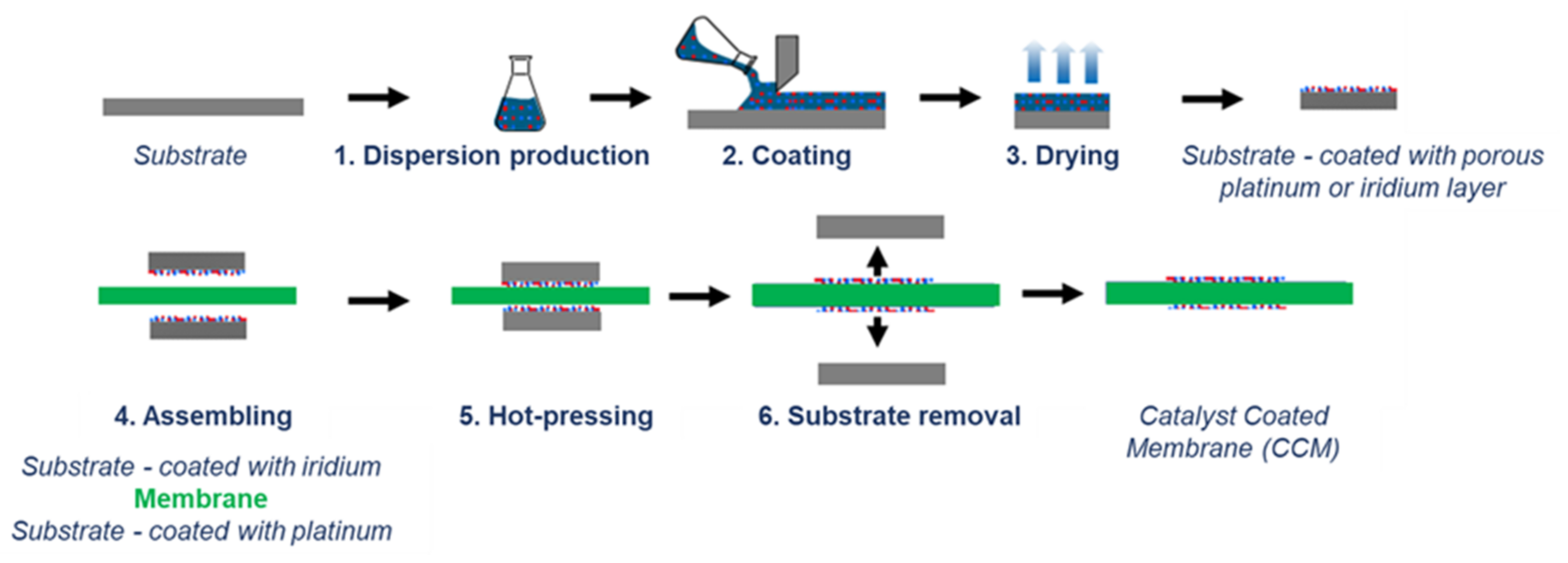
For the production of MEAs in the MW scale, it is important that the manufacturing processes used meet the requirements for scalability and production speed. The transfer or decal method outlined in
Figure 2 meets these requirements. The process steps used, such as coating a substrate with a catalyst dispersion using a doctor blade or slot die and the subsequent drying, can be carried out in a laboratory or a roll-to-roll process. This also applies to the subsequent assembly process where the dried catalyst layers are transferred from substrate to a membrane with a hot pressing process.
The production of MEAs for PEM water electrolysis faces the challenge of increasing the electrochemical efficiency of the MEAs and structuring the entailed processes in such a way that they are scalable and can be mass-produced. The electrochemical efficiency of MEAs partially depends on the thickness of the membrane used, as the protons flowing through the membrane during cell operation induce ohmic losses. This requirement can be fulfilled using the aforementioned decal process in which the thinnest possible membranes are used during assembly. However, a compromise must be made between membranes that are as thin as possible but still easy to handle in the production process.
Scalable processes, such as slot die or blade coating, are ideal for the industrial-scale coating of a substrate. A disadvantage of blade coating (a form of self-metered coating) is that the homogeneity of the coating cannot always be precisely controlled [
70], whereas slot dies (which allow for a pre-dosed coating) can produce highly homogeneous coatings in combination with homogeneous substrates [
71]. The possibility of pre-dosing means that the catalyst loading of the electrodes can be precisely adjusted by means of the dosing rate of the pump and the coating speed, provided that the dispersion composition is known. As the MEAs in the stack are connected in series for PEM electrolysis, it is highly important that the electrodes are identical and that the rolls of electrodes being produced from which the electrodes are subsequently cut are also homogenous. The specifications shown in
Table 2 were applied for the catalyst loading of the MEAs being produced for the MW electrolysis system.
A Premion (Alfa Aesar) IrO
2 catalyst was used as the anode catalyst and a Pt/C 60% high surface area (HAS) Ketjen Black (Fuel Cell Store) catalyst was used as the cathode catalyst. The Nafion NR212 membranes were purchased from Chemours. An additional specification was the use of a recombination catalyst to be inserted into the MEA to break down the hydrogen permeating through the membrane with oxygen and thus minimize the safety risk presented by oxy-hydrogen formation during operation of the stack. As previously published methods of use of such recombination systems [
72,
73] could not be scaled to the required production size, a new method was developed and used for the production process described in the following sections [
74].
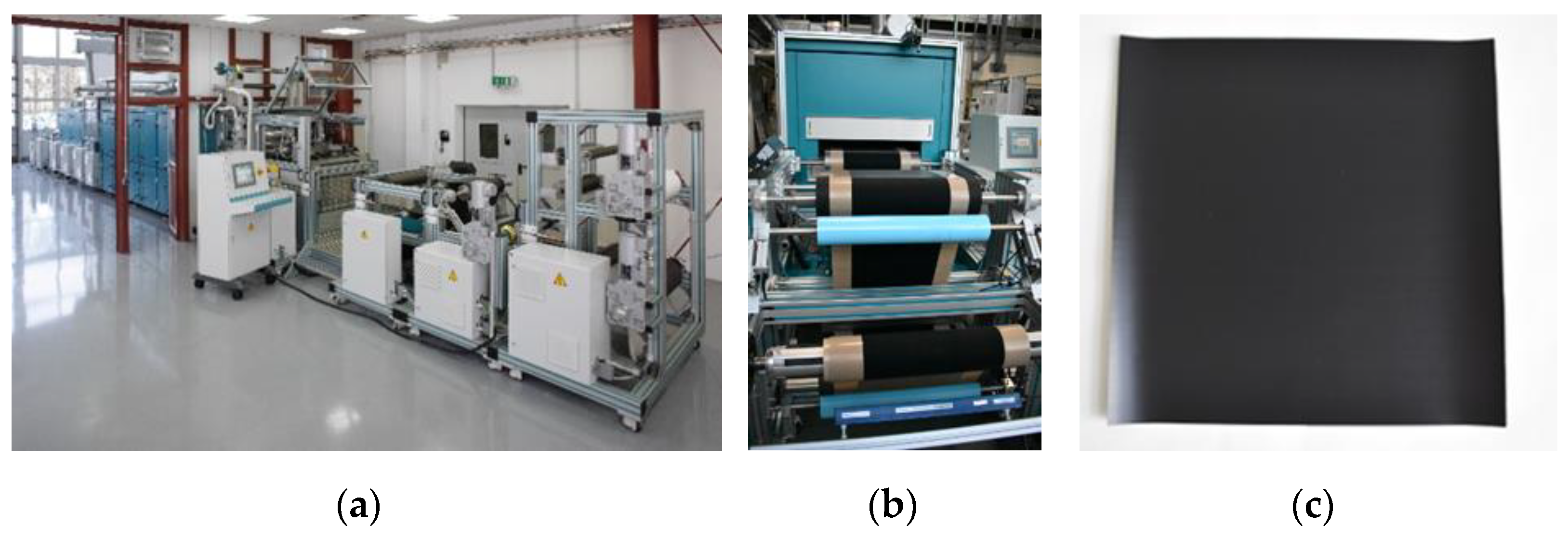
Dispersions were produced from the catalyst powders that were applied to a fiberglass-reinforced polytetrafluoroethylene (PTFE) roll in the roll-to-roll coating system (
Figure 3a) by means of a slot die. During drying, it must be ensured that the combination of solvent evaporation and the formation of layers does not lead to layer defects and the flaking of dried layers [
75,
76]. The specific machine settings were determined in preliminary tests. After drying, the coated material was rolled up (see
Figure 3b) and the electrodes were cut from the roll with dimensions of 32.5 × 32.5 cm
2 (see
Figure 3c).
After producing the anodes and cathodes, they were assembled together with the Nafion NR212 membranes using hot presses from P/O/Weber. After pressing, the substrates were then removed from the cooled MEAs, which were then completed (see
Figure 4).
For the purpose of quality assurance, samples were taken from the rolls of electrodes to produce MEAs for laboratory cells and for the electrochemical characterization of the MEAs.
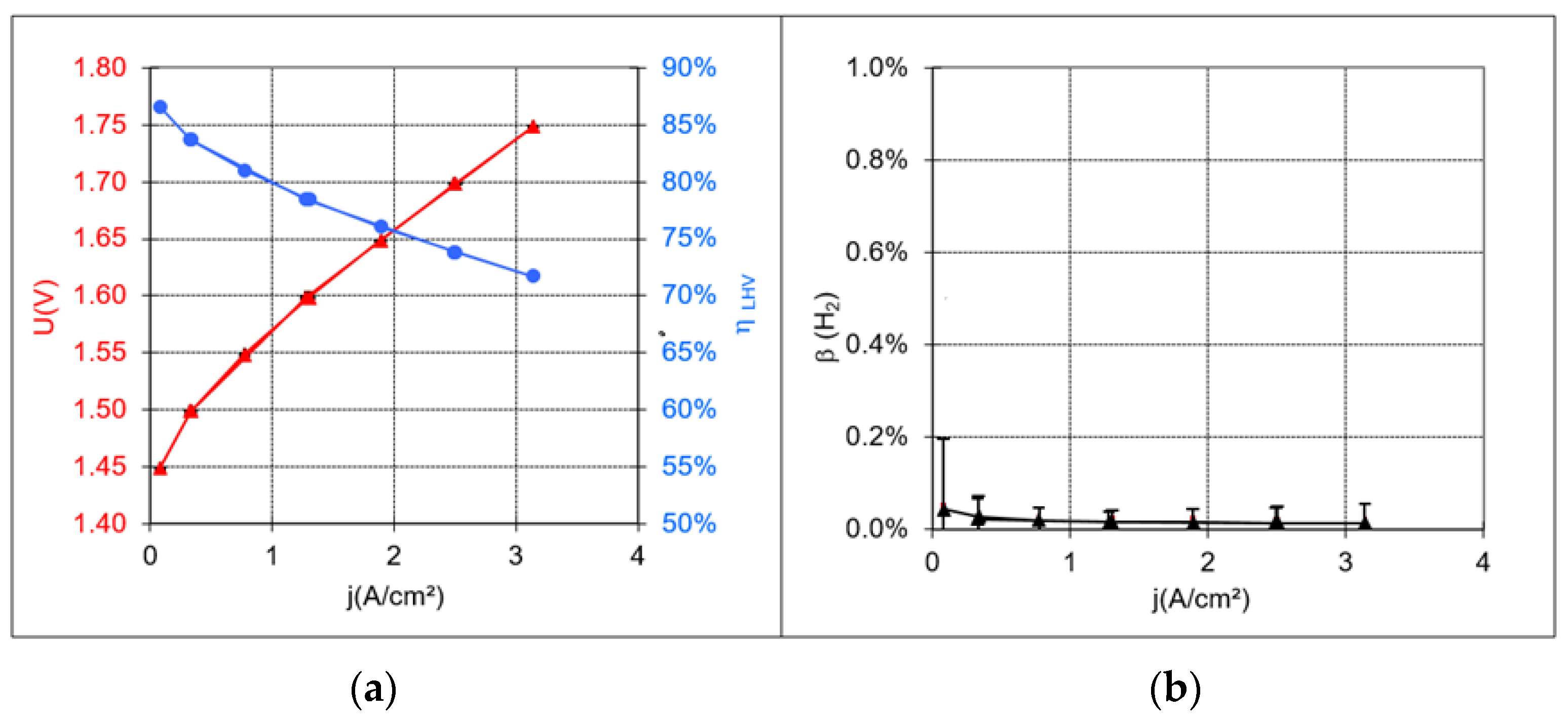
Figure 5 shows a polarization curve plotted from the characterization measurements, an efficiency curve, and a graph demonstrating the proportional volume of hydrogen in the anode gas. The latter clearly shows that safe operation can be achieved with the MEAs produced, even with small current densities. Within the scope of measurement uncertainty, no hydrogen could be detected as a result of the recombination catalyst being used.
3.2. Compact, Efficient, and Robust Cell Components
The previously considered MEA is a component that plays the main role in producing hydrogen in electrolyzers. It is here that the electrochemical water splitting reactions and the generation of heat occur due to operational and material-related overvoltages. However, as indicated by the setup of the MEAs, additional cell and stack components are required to produce hydrogen in MW electrolyzers on an industrial scale. The entire assembly of the electrolyzer must support the following process functions:
Introduction of electrical current and feed water;
The homogeneous distribution of current and feed water to all active areas;
Safe removal of produced hydrogen (H2) and oxygen (O2);
Safe separation of H2 and O2 spaces;
Sealing of the media from their surroundings;
Heat dissipation in the entire area of operation.
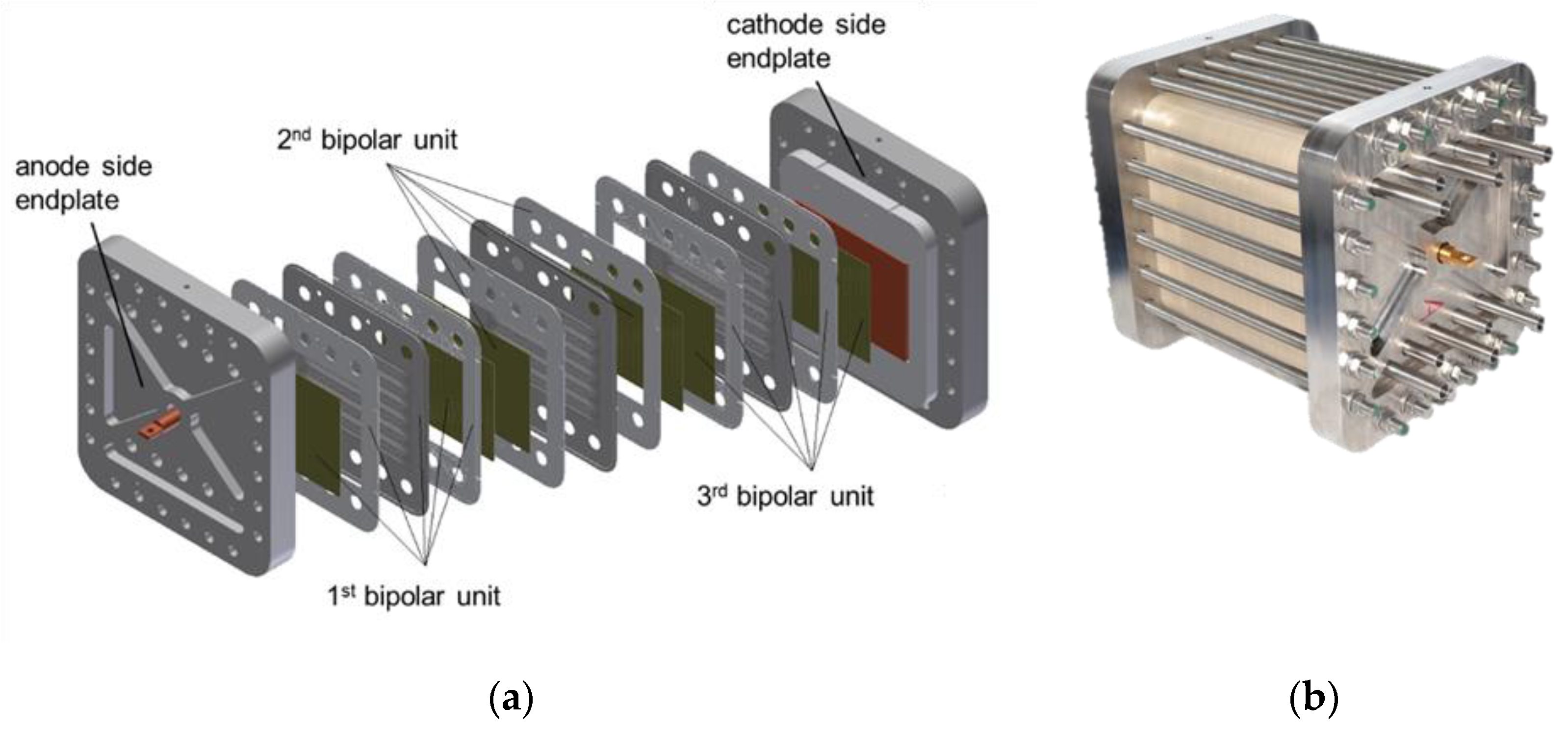
On the left-hand side of
Figure 6 can be seen an exploded view of an electrolysis stack from the Ekolyser project (funding reference no. 03ESP106A) being funded by the Federal Ministry for Economic Affairs and Energy (BMWi). The stack is closed off by two massive end plates through which the media are added and removed and through which the power connection is made. The combination of end plates and tie rods also ensures that the inner components are pressed together. A defined contact pressure helps to ensure that the components are sufficiently sealed and that they have electrical or mechanical contact. The contact pressure is adjusted via the tractive forces in the tie rods. A distinction must be made between two areas: the active cell area and the sealing area. Although the optimal contact pressure on the active cell area is 2–3 MPa [
44], the required pressure on the sealants is dependent on the sealing concept. The inner components are the repeating units of the electrolysis stack. A repeating unit always consists of one bipolar unit and one MEA. In
Figure 6a, three bipolar units are shown. The MEAs (not shown here) are each arranged between the bipolar units. The active cell area is 300 cm
2 (10 cm × 15 cm). In
Figure 6b, an assembled electrolysis stack comprising 27 cells can be seen. The stack is designed for an electrical power supply of 50 kW with a maximum operating pressure of 50 bar.
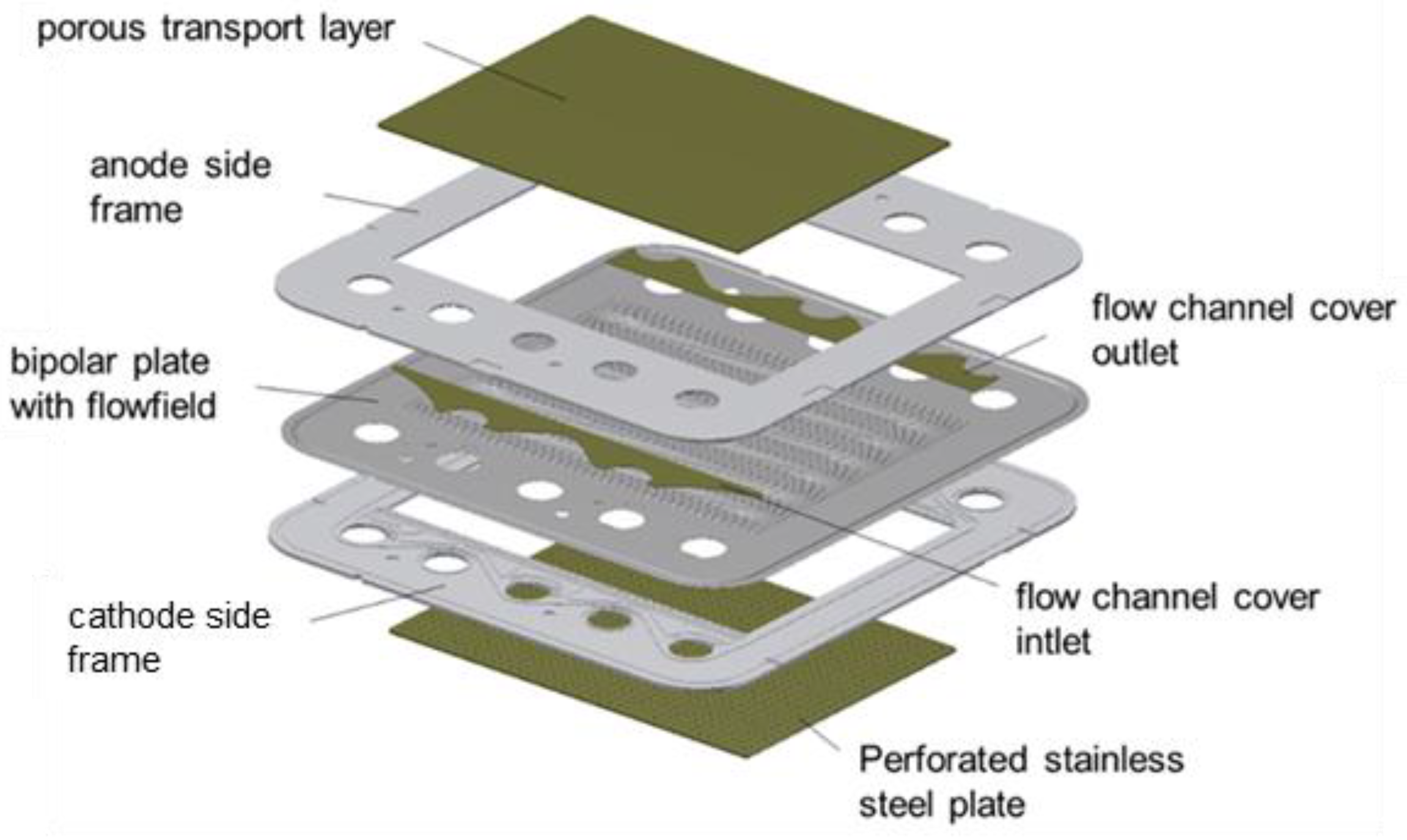
Developed as part of the Ekolyser project, the bipolar unit with seven individual components is shown in
Figure 7. The central aspect of the bipolar unit is the bipolar plate, which separates the anode and cathode sides of the two adjacent electrolysis cells in a gas-tight manner. The bipolar plate is made of stainless steel 1.4404 (316L) and also features flow distributor structures that are produced by hydroforming to distribute the feed water equally across the active cell area and to remove the produced gases—oxygen on the anode side and hydrogen on the cathode side—with surplus water. The bipolar plate is enclosed on both sides by a polyether ether ketone (PEEK) frame. The frames feature distribution and collector structures for the inflow/outflow of media (water and two-phase flow) from pipes installed at the end plates (see
Figure 6b) to the respective cell level. Additional covers made of stainless steel are required to provide mechanical support for sealants (not shown) in the distribution and collector structures. The frame cutouts admit fine distribution structures of varying porosity on the anode and cathode sides. The anode side features a layer of sintered Ti powder. A perforated stainless steel plate is used on the cathode side. In addition, a carbon fiber layer can be found on the MEA side, which is not shown in
Figure 7.
A significant drawback of this bipolar unit is the fact that all components must be individually laid on top of each other when assembling the stacks. For the 27-cell stack shown above, the individual parts (including O-rings) amount to around 600 for the repeating units alone. The assembly of the stacks is extremely time-intensive and there is also the potential for sources of error, which can lead to malfunctions in stack operation. These include leaks outside and within the stack, as well as inhomogeneities in contact pressure distribution. The higher the number of individual components, the greater the likelihood of errors occurring during assembly. The dimensional tolerances of the components and the shifting of components during assembly play a key role in ensuring the quality of the entire assembly.
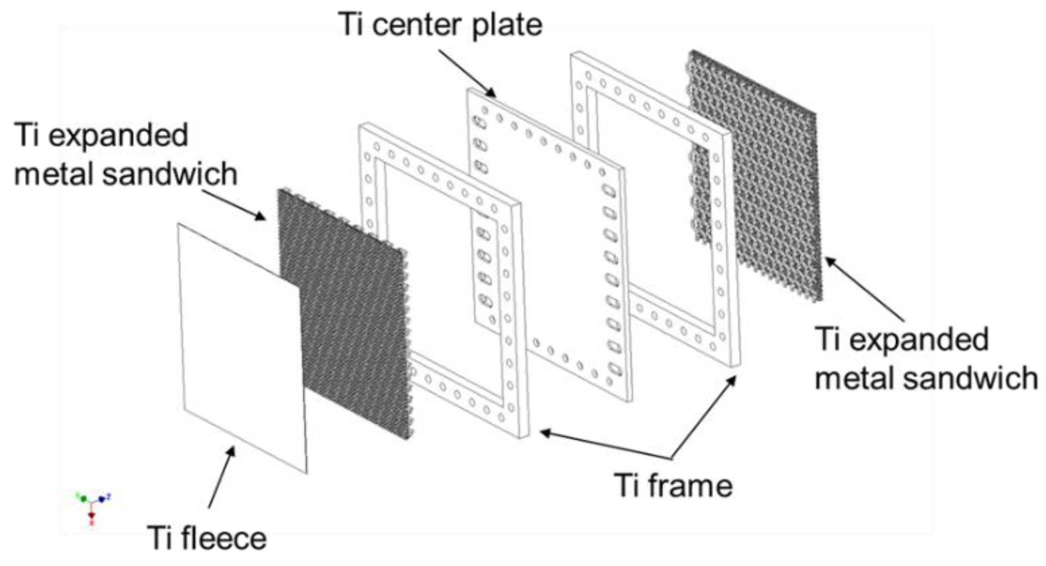
To counter this problem, the development of a “one-component bipolar unit” was initiated as part of the Energy Lab 2.0 and LLEC projects. Another aspect to consider was that only cost-effective, readily available raw materials should be used. The active cell area also had to be significantly increased to approximately 1000 cm
2 in order to advance development towards MW electrolysis. The starting components for the newly developed bipolar unit are shown in
Figure 8. A distinguishing feature of the bipolar unit is that all of its components are comprised of Ti. According to Lædre et al. [
77], Ti is a material that exhibits good corrosion stability under electrolysis conditions. To counteract degradation effects, an additional coating may need to be applied to the contact areas of the MEA. The setup shown in
Figure 8 reveals a simple central plate with drill holes and elongated holes for the supply of media. The double-sided simple frames merely contain holes that enable media to pass through. Three-part expanded metal sandwiches are inserted into the frame interiors. The elongated holes in the center plate allow the media to flow in and out of these areas. The expanded metal sandwiches serve as flow distributors. A Ti fleece acting as a fine distribution structure can be found on the anode side of the bipolar unit.
All previously described components are connected to each other in an interlocking manner by means of diffusion welding. This process takes place in a vacuum oven in which the stacked components are heated by thermal radiation up to a temperature close to enabling phase transition (882 °C for Ti). When the desired temperature is reached, a defined pressure is applied to the components through a mobile stamp in the oven.
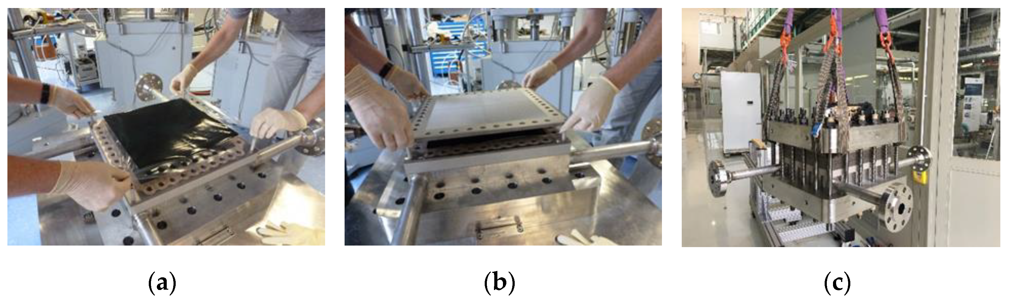
As is shown in
Figure 9, the stack assembly can be handled manually and easily by two people. Simple assembly aids in the form of plastic rods enhance the positioning accuracy of the components. The repeating units now comprise the following components: a bipolar unit, flat gasket, carbon fiber sheet, and an MEA. In
Figure 9c, a fully assembled short stack can be seen. The performance and long-term behavior of the stack in operation has yet to be determined and will be documented and discussed in a later publication. The nominal power of a stack with 70 cells of this type will be in the range of 400 kW.
3.3. Design and Setup of the Test Facility
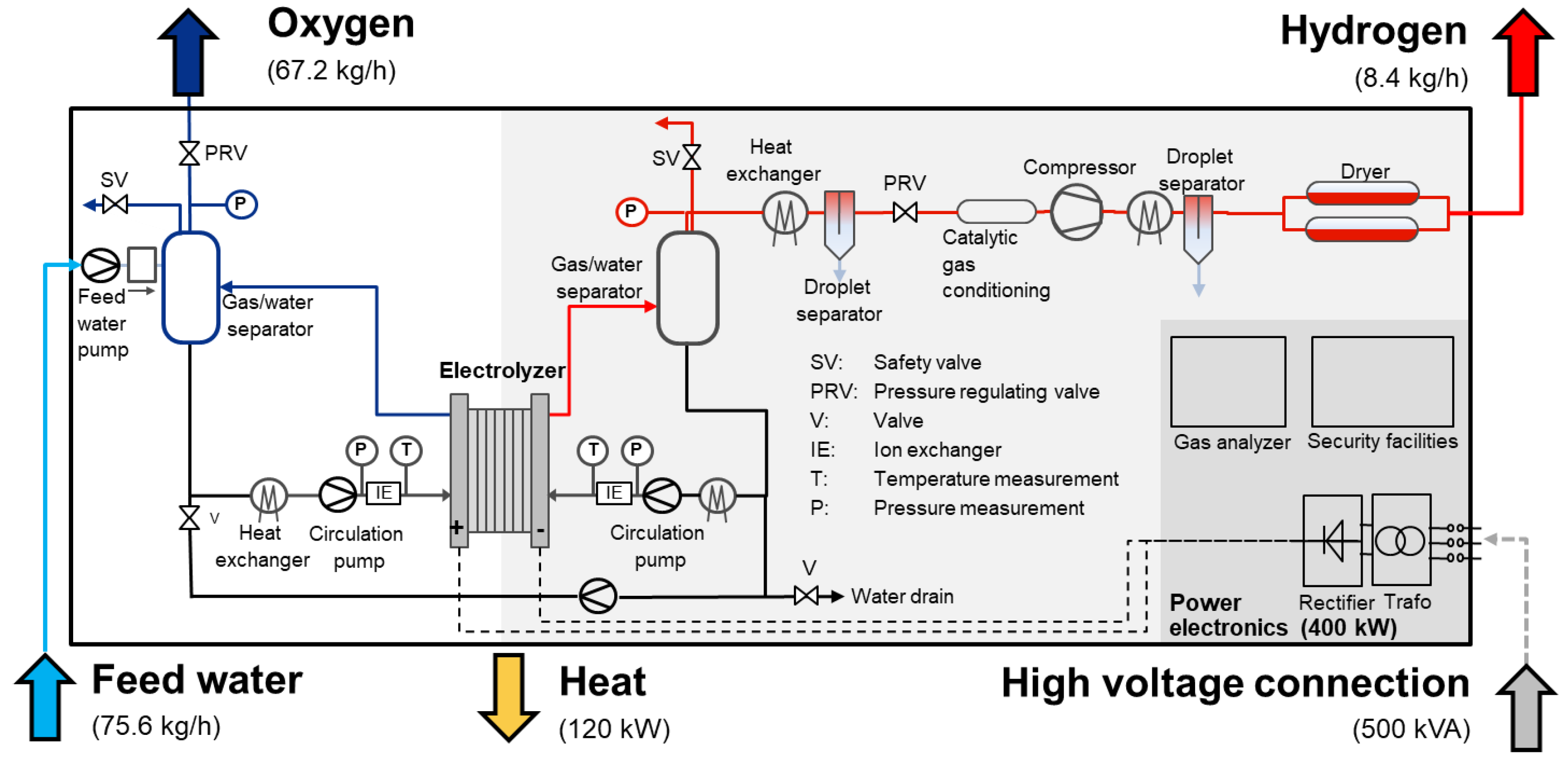
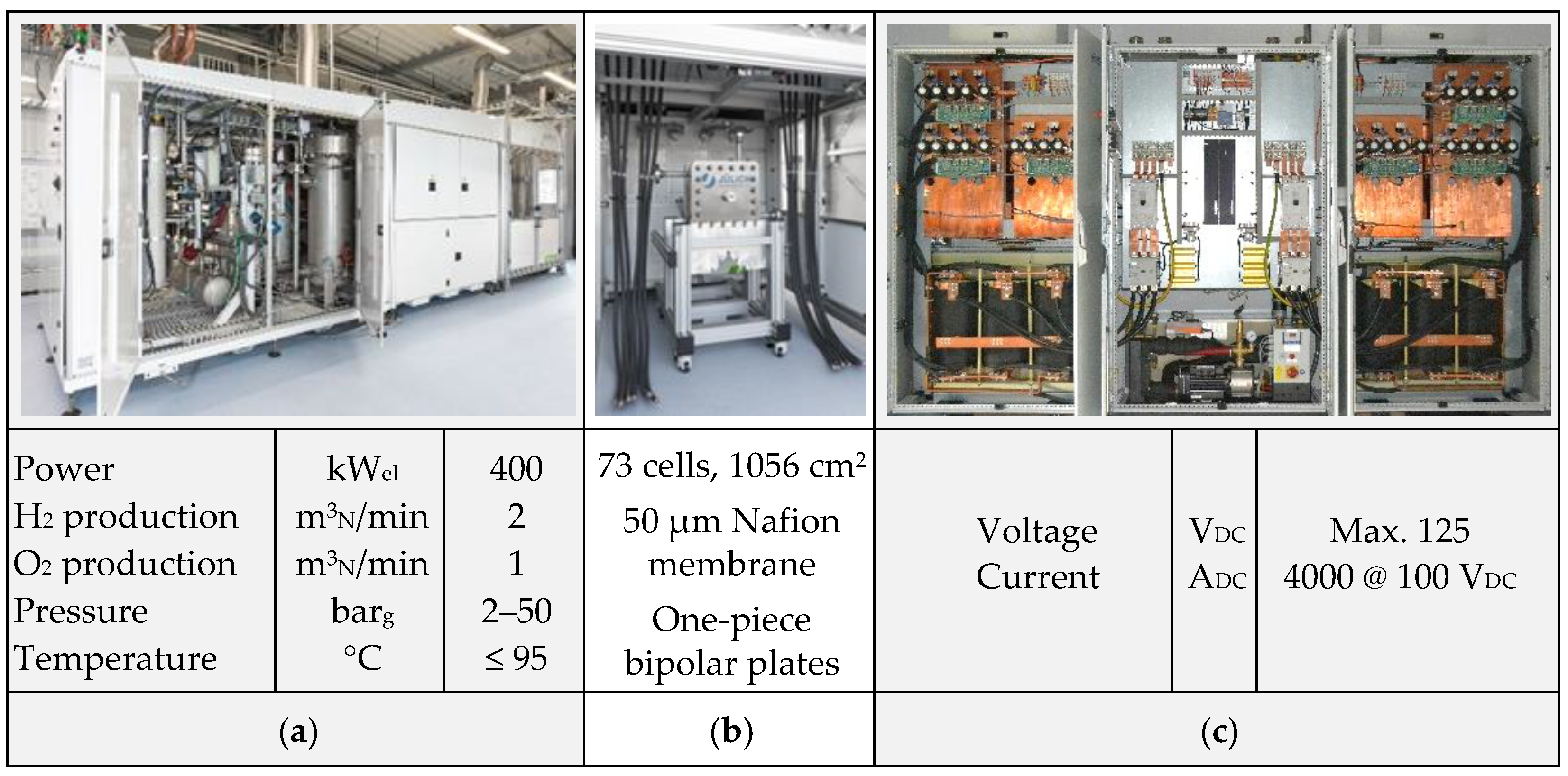
On the basis of interdisciplinary approaches, Jülich researchers and engineers work on electrolysis technologies at various stages of development. A relatively new technology for industrial-scale application is polymer electrolyte membrane water electrolysis, which features dynamic operation and a high overload capacity. A new test facility, which is unique in this way, was developed in close collaboration with the Canadian company Greenlight, which is schematically illustrated in
Figure 10. The test facility allows for the comprehensive characterization of PEM electrolysis stacks with an electrical output of up to 500 kVA with current intensities of up to 4000 A
DC/10,000 A
DC. The pressures can be flexibly adjusted between 4 bar and 50 bar for the anode and cathode circuits. Characterization can thus be flexibly performed at various pressure levels with balanced pressure or differential pressures.
The main features of the test facility are as follows: power electronics enable the conversion of 400 VAC mains electricity into direct voltage up to 125 VDC. The anode and cathode are each fitted with their own gas/water circuits, which are used for heating and cooling the stack as well as supplying it with water. The gas separators also separate the converted water from the produced gas in the circuits and can regulate the produced gases at pressures of up to 50 bar by means of membrane pressure regulators. Therefore, the gas can be made available for consumers or temporary storage. For stable and disruption-free electrolysis operation, the regulation of pressure to minimize the differential pressure between the two gas circuits is very important. The deionized fresh water required for electrolysis is supplied by an in-house system and introduced to the test stand using a booster pump in accordance with the current operating pressure. In addition to regulating pressure, the temperature is also optimally regulated, which has a significant influence on achieving optimal operation and helps to compensate for highly dynamic load changes and the resulting waste heat as quickly as possible.
Comprehensive recording and processing of the measurement data allows for automated operation under predefined load profiles and ensures the transfer of data to overarching control systems of EnergyLab and LLEC living labs, which are described in the following sections. Data are connected to the control systems of the LLEC, which enables optimal electrolysis operation in terms of energy efficiency and performance in the entire network of systems by means of a specially initiated data exchange in the Jülich virtual local area network (VLAN). The protocol used for the data exchange is based on the message queuing telemetry transport (MQTT) network protocol. The MQTT is very well suited for large networks of systems with high data transfer rates, as is predominantly the case with automation technology. Therefore, it is important that all units in the LLEC are equipped with an MQTT protocol. All required data are collected and evaluated centrally with the LLEC’s control systems. To enable optimized operation in the entire network of systems, the desired values must be transferred to the available systems in addition to the evaluated data. This again takes place using the MQTT protocol to ensure optimized control at the highest control level. The electrolyzer itself is then capable of regulating the desired values and can implement the provisions of the LLEC’s control system. Safety-based limits for the LLEC’s desired values are integrated into the test stand control system and help protect the personnel and systems.
The test facility shown in
Figure 11a enables the integration of various PEM electrolysis stacks up to an electrical power input of 400 kW for an active cell area of up to 1200–3000 cm
2 if the power electronics reserve is expanded for currents of up to 10,000 ADC.
From a safety perspective, the legal and operational provisions were implemented, adherence to which was confirmed by successful inspections of the Technical Supervisory Association (TÜV), particularly in the areas of explosion protection and pressure equipment. From a technical standpoint, many of the required inspections were performed with the aid of a safety-oriented programmable logic controller (PLC).
The entire electrolysis system is part of a technical center that is equipped with the necessary facilities for the supply of media and energy, as well as the forward transport, conditioning, and removal of all products from the electrolysis process. The technical center also features the technical facilities required for ventilation and the safe removal of media, as well as a control room in which all measurements are recorded and processed.
3.4. Energy Lab 2.0: Real-Life Laboratory and Simulation Platform for the Energy-Related Testing of Sustainable Conversion and Storage Technologies
Energy Lab 2.0 [
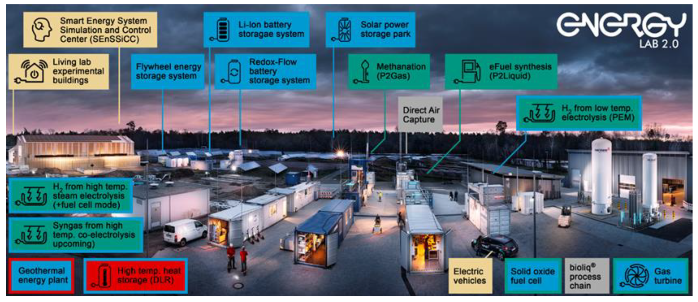
78] is a large-scale research infrastructure of the Helmholtz Association. Its mission is to develop technological solutions for a smart and integrated energy system for a defossilized future. Energy Lab 2.0 allows for technology-oriented research on a demonstration scale in order to successfully integrate renewable energy (RE) into the power grid.
In particular, all relevant components of a future energy system are considered, namely RE generation, storage and grid integration, and power-to-X conversion technologies (X = gas, liquid, heat)—all complemented with a comprehensive system analysis. At Karlsruhe Institute of Technology (KIT), the majority of the components have been set up. Moreover, certain components are located at the German Aerospace Center (DRL) in Stuttgart (Germany) and Forschungszentrum Jülich (Jülich, Germany), respectively (see
Figure 12).
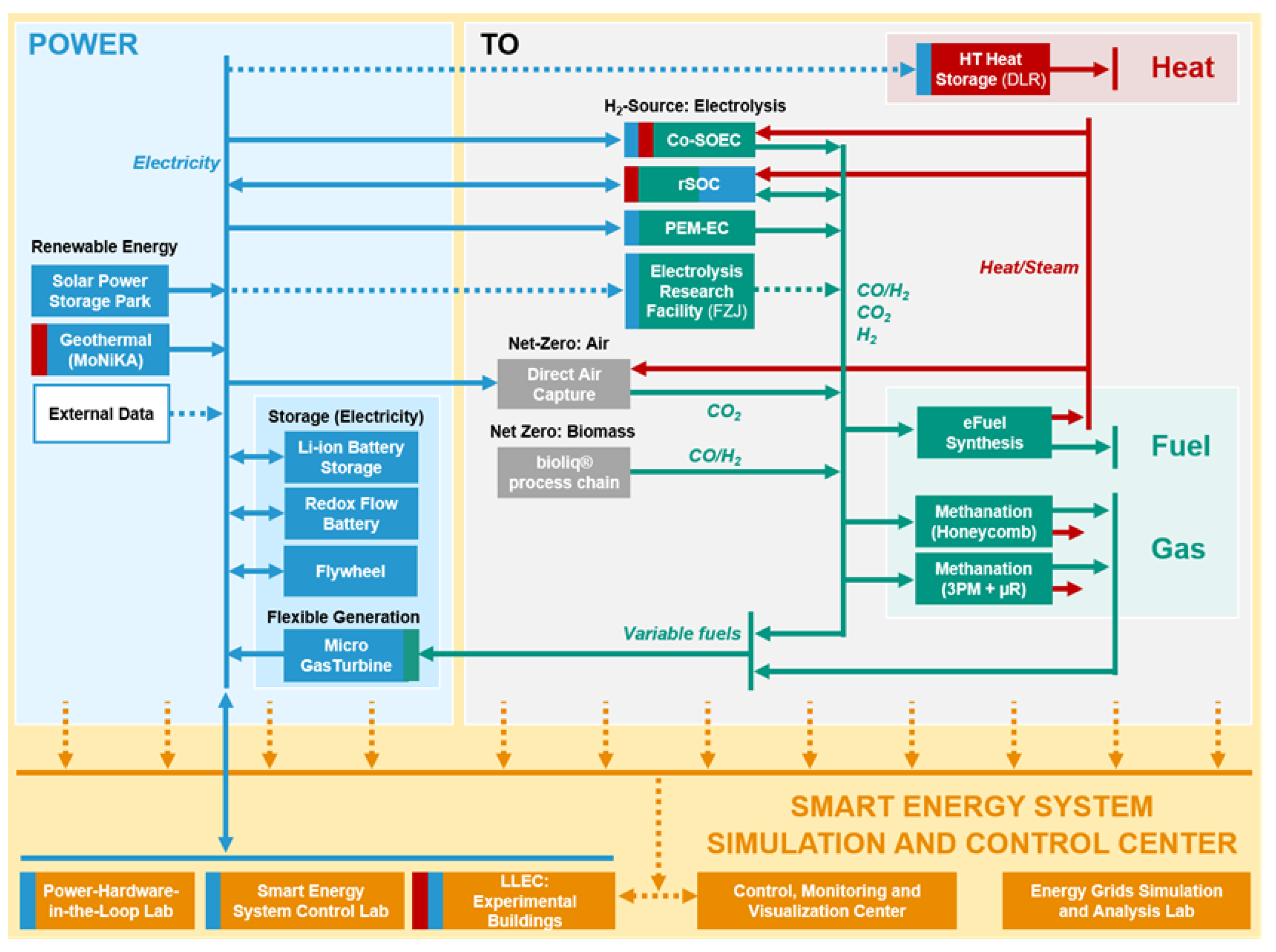
For the Karlsruhe site, research at the Energy Lab 2.0 can be subdivided into three major areas: (1) the solar power storage park mainly focuses on short-term energy storage via different types of batteries, whereas the plant network (2) targets chemical energy carriers (power-to-molecules), and (3) the Smart Energy System Simulation and Control Center (SEnSSiCC) focuses on power hardware, the power grid, and consumers/prosumers both experimentally and via simulations. In order to investigate and demonstrate the coupling of the different components, plants are interconnected and can be operated within a smart grid design of interest (see
Figure 13). Furthermore, power-to-heat is focused on at the DLR (Stuttgart, Germany), whereas major research is conducted on electrolysis at Forschungszentrum Jülich (Jülich, Germany).
3.4.1. The Solar Power Storage Park of the Energy Lab 2.0
A solar power storage park was built at KIT back in 2014. This storage park includes a 1 MW
p photovoltaic (PV) system, as well as smaller storage systems. In addition, a 1.5 MWh Li-ion battery and an 800 kWh redox flow storage system were integrated into the park as part of the Energy Lab 2.0 project. Storage systems on a large scale will only be used when their deployment is economically-viable. Economic viability is not only influenced by the investment costs but also by the lifetime and design of the systems, the system control, and system design, including their overall efficiency. The impact and optimization potential of these aspects in terms of the economic viability of the systems are being investigated as part of various projects centered around the Energy Lab 2.0. Efficiency losses in such storage systems can occur, for instance, due to the high cooling and heating requirements. In order to reduce these losses, an innovative cooling concept was developed for the 1.5 MWh Li-ion battery, which was integrated into a concrete structure. The thermal component activation of the concrete structure and the use of groundwater to control the temperature of the batteries by indirect water cooling ensure minimized system operating costs (through increased efficiency) and a long lifetime for the battery modules as a result of the enhanced temperature control. There also exists the potential to optimize redox flow batteries (RFBs) in terms of efficiency [
79]. In addition, research on intelligent operating strategies is being conducted on RFBs and Li-ion batteries. In the majority of cases, the operator of a Li-ion storage system is provided with information on the state of charge. However, the actual state of charge and the battery’s usable energy depend on the system’s discharge capacity. A model that is capable of self-learning during operation is currently being developed and would be able to provide information on the state of energy of the entire storage system. Furthermore, one of the smaller storage systems is being operated to replicate a Li-ion storage system in a multifamily home and is virtually connected to a part (30 kW
p) of the 1 MW
p PV system.
Li-ion batteries are subject to particularly strong degradation if they are in a high state of charge for a long period of time. This can be reduced through an intelligent operating strategy [
80,
81]. PV and load forecasts are both vital components for arriving at such intelligent operating strategies. Currently research is being conducted to determine which type of PV forecasting methods are best suited for intelligent charging strategies [
82].
3.4.2. Power-to-Molecules in Decentralized and Highly Efficient Plants
In the future energy system, “power-to-molecules” technologies will be an important piece of the overall puzzle, not only as an option for chemically-storing electrical energy, but also as a source for CO2-neutral fuels and chemical feedstocks. Within the plant network of the Energy Lab 2.0, there is a focus on the synthesis of hydrocarbons—namely methane and Fischer–Tropsch-based fuels—from CO2 and H2. Although green hydrogen can be obtained through electrolysis, non-fossil CO2 must be captured from the air (direct air capture—DAC), generated from biomass, or separated from unavoidable industrial point sources that cannot be decarbonized, for example, by electrification. At the Energy Lab 2.0, a PEM electrolysis unit (100 kWAC nominal power, operating pressure of up to 47 bar) and a high-temperature reversible steam electrolysis/fuel cell unit (electrolysis mode: 150 kWAC; fuel cell mode: H2: 25 kWAC, CH4: 20 kWAC) are used to investigate integration into certain process chains. Within the Kopernikus Project “P2X”, funded by the German Federal Ministry of Education and Research, a high-temperature co-electrolysis system will be installed. In order to capture CO2 from ambient air, DAC is integrated into the plant network, for example, within the framework of the Power-Fuel project funded by the German Federal Ministry for Economic Affairs and Energy.
Predetermined by the local and temporal availability of both non-fossil CO
2 and green electricity in a future defossilized energy system solely based on renewable energy, power-to-molecule process chains must be tolerant to input fluctuations (not only in terms of minutes but also on a day/season scale) and intensified, also allowing for decentralized application. Dynamic operation and process intensification are the major objectives investigated in the synthesis plants at the Energy Lab 2.0, namely the three-phase methanation [
83] (output equivalent to 100 kW) and eFuel synthesis plants (1 bpd Fischer–Tropsch products).
While conventional plants for eFuel synthesis, for example, via the Fischer–Tropsch (FT) route, are designed for steady-state operation due to several hurdles such as hot-spot formation; in contrast, process intensification enables the reactor’s volume and plant’s complexity to be reduced [
84]. This is why, in the eFuel synthesis plant (INERATEC GmbH) of the Energy Lab 2.0, a modular microchannel-based reactor is used. Projects utilizing the Energy Lab 2.0′s infrastructure investigate the benefits of process-intensified and modular equipment on the design of the process chain. For example, in the PowerFuel project, the required tank size for buffering the hydrogen produced from renewable sources was investigated. The results show that it is possible to drastically reduce the intermediate tank size due to the ability of the microchannel-based FT reactor and of the eFuel synthesis plant in general to operate under reduced feed within a response time of a few minutes [
85].
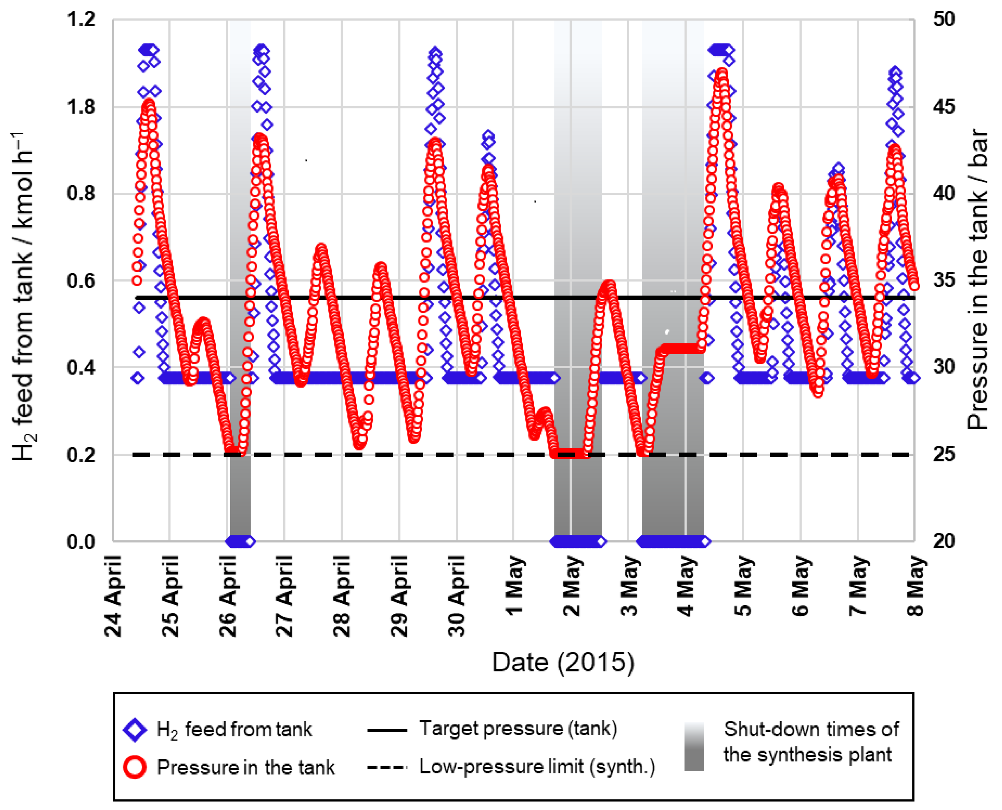
In a study conducted at KIT, the eFuel synthesis plant of the Energy Lab 2.0 was simulated in AspenDynamics within the framework of the aforementioned PEM electrolyzer plant (160 kW
AC overload situation), the 50 m
3 hydrogen tank (which corresponds to up to 2300 Nm
3 H
2) and an assumed 320 kW
p PV field with experimentally-determined power profile data of the solar power storage park (two weeks in the spring of 2015). The electrolyzer in this scenario was assumed to instantaneously follow the PV profile (with a 10 min temporal resolution). Only the ramp-up was capped in the model, as at least 40% of the nominal load was required to run the system experimentally. It was shown that the control strategy applied for the synthesis plant significantly influences the number of required shutdowns enforced by the unsteady supply of electrical energy and, thus, hydrogen in such a scenario. When running the synthesis plant under steady-state conditions, its operating time can be as low as 35% and 48% when applying constant H
2 feed equivalent to 150 kW
el or 115 kW
el electrolyzer load, respectively. In contrast, when running the synthesis plant dynamically, depending on the hydrogen production rate or a desired tank pressure level (see
Figure 14), the operating time can be significantly increased to 70% or even 83%, respectively.
For dynamic synthesis operation, it was also shown via experiments on a relevant lab scale (H
2 feed equivalent to 500 W
el electrolyzer load) that the ability of micro-structured reactors to cope with feed fluctuations does not influence the product quality, nor does it induce complete hydrogen consumption in the FT reactor, which could harm the catalyst due to the presence of the remaining CO. This is affected by the possibility of effectively controlling the reactor temperature [
86].
3.4.3. The Smart Energy System Simulation and Control Center
The necessary coupling of various energy sectors in future and the fluctuation in the generation of power from renewable energy sources present an enormous challenge regarding the control and operation of future energy systems. In order to perform control and monitoring tasks under the most realistic conditions possible, the Smart Energy System Simulation and Control Center (SEnSSiCC) [
87] was established as part of the Energy Lab 2.0 project. The SEnSSiCC brings together work on information technologies and the corresponding research aspects of the Energy Lab 2.0 (see
Figure 13 and
Figure 15).
The following sub-labs form the SEnSSiCC: the Smart Energy System Control Laboratory (SESCL), which acts as a representation of the real power grid of the future where the most important energy systems are flexibly interconnected through a busbar matrix, ensuring that experimental configurations can be quickly changed; the Energy Grids Simulation and Analysis Laboratory (EGSAL), where the topography of future energy grids is simulated with the virtual integration of components [
88] that are not available at KIT’s Campus Nord; the Energy Lab 2.0′s Control, Monitoring and Visualization Center (CMVC), where software tools are being developed for the control room of future energy grids [
89]; and the power hardware-in-the-loop (PHiL) laboratory test environment, which enables real hardware components to be integrated into a simulated 1 MVA grid and subjected to stress tests, as in [
90]. The SEnSSiCC is complemented by the Living Lab Energy Campus (LLEC, see the next chapter), also a research infrastructure of the Helmholtz Association. Three experimental buildings with identical constructions are connected to the SEnSSiCC in terms of electrical technology and data and thus expand the portfolio of energy technology systems used for experiments.
The Smart Energy System Control Laboratory focuses on the support of developments and innovations in the field of smart grids under realistic conditions. The SESCL is a laboratory in which state-of-the-art energy technology systems and new control algorithms are developed and tested [
91]. This laboratory is galvanically isolated from the public grid, so that the control algorithms can be approved and investigated in limit ranges (frequency, voltage). In addition, it is possible to control operating points approaching the limits of stability. Such experiments would not be possible using the public grid, as the risk of a complete grid failure is too high. In order to conduct experiments on low-voltage networks under realistic conditions, the laboratory provides a number of energy systems, such as electricity generators (e.g., PV systems, wind power units), electrical machines, generators, inverters, storage systems (e.g., Li-ion batteries), and charging stations, that can be very flexibly interconnected by taking into account the physical properties of the connecting lines to form a micro-grid with a variable topology. To model the operating behavior of the cable/overhead lines, the laboratory features real means of transmission and line replicas that physically simulate this behavior using discrete resistor–inductor–capacitor (RLC) components. In terms of the interconnection, flexibility is ensured by a matrix of alternating and direct current busbars and contactors that are controlled by a centralized automation system. Load shedding and the addition of further producers and consumers, or a combination of the two (prosumers) can be achieved very easily.
3.5. Living Lab Energy Campus: Integrated Research Platform for Energy-Related Coupling of Pioneering Conversion, Distribution, and Storage Technologies
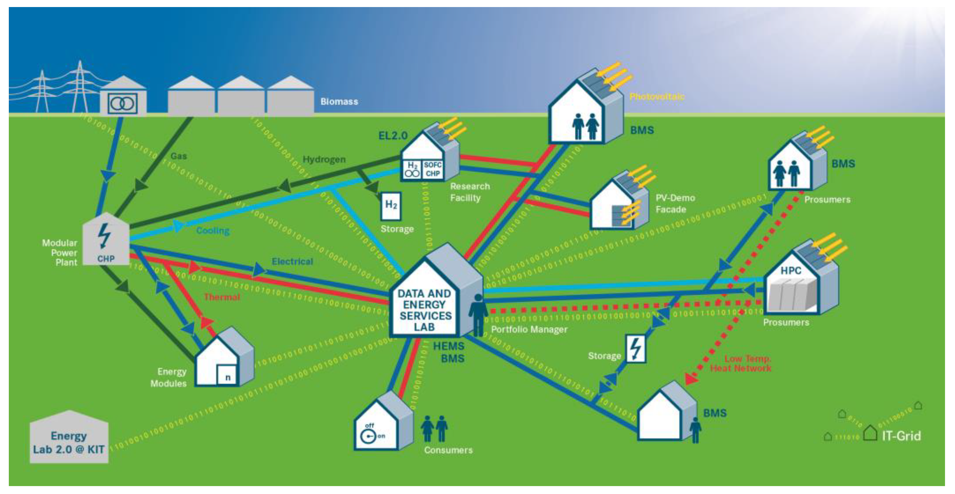
The Living Lab Energy Campus (LLEC) project is an integrated research platform (see
Figure 16) for the coupling of electrical, thermal, and chemical energy flows through an intelligent sensor and control system. Various production, distribution, and storage systems are integrated into the energy supply of the research campus and are then monitored and optimally controlled according to predefined constraints by an adaptive, cloud-based, and model-predictive IT platform. In addition, digital models have been developed for different energy grids, energy demonstrations, and various building types. The demonstrations include various photovoltaic systems, two large Li-ion batteries, a low-temperature waste heat network, and a hydrogen sector with a high level of sector coupling. A large number of sensors collect data via the fluctuating energy flows at the research site. A special significance is attached to achieving an optimal interaction between humans and technology.
A thermal energy center (WVVZ) designed as a modular system supplies the campus with electrical energy and heat. To this end, gas mixtures comprised of natural gas with biogas and hydrogen are used in the installed gas engines. An additional low-temperature network uses waste heat from the JUWELS supercomputer to supply heat to the surrounding buildings by means of heat pumps and simultaneously investigate the electrical and thermal utilization of the network, as well as potential resource savings. Various photovoltaic systems form the basis of the renewable energy supply and are integrated into the energy system in the form of conventional rooftop installations, free-standing modules, and modules fixed to the building façade. The fluctuations in the energy feed that occur are offset by two large Li-ion batteries. At the same time, these batteries serve as an uninterruptible power supply for a selection of sensitive research infrastructures. The LLEC was recently expanded to encompass research issues surrounding vehicle-to-grid (V2G) systems. Various bidirectionally operable charging infrastructures for electric research vehicles are currently being established.
One system- and process-related focus of the LLEC is the long-term and seasonal storage of renewable energy using hydrogen from the MW electrolysis system. As is shown in
Figure 1, hydrogen and oxygen from the water electrolysis process each flow through a pressure-resistant pipeline, with only the hydrogen flowing into a pressure tank as additional storage. The hydrogen can also be stored in LOHCs. The loading and unloading of the LOHC takes place in a novel one-reactor system, which for the first time, demonstrates both process steps in a system with a performance of 300 kW
p. The level of heat required for hydrogenation is approximately 300 °C and is obtained from the waste gas of the gas engines. The heat that is generated during dehydrogenation is supplied to the heat supply system on campus. Significantly higher rates of storage efficiency are achieved through this type of sector coupling. All forms of storage enable the stockpiling of gases over many weeks and months before hydrogen can be used to generate electricity and heat in the WVVZ’s gas engines, and hydrogen and oxygen are able to do the same in an alkaline fuel cell.
As they are incorporated in a climate-neutral office complex, all of the energy systems can be monitored in the Data and Energy Services Lab, where researchers are also able to plan and evaluate future energy system experiments together with their colleagues from the technical infrastructure department.
4. Conclusions
This article describes the detailed design and unique capabilities of the test facility for large-scale electrolysis stacks that produce substantial quantities of hydrogen with a high degree of efficiency and virtually interact with various other facilities in a future renewable energy system.
In contrast to the methods using ceramic or alkaline electrolytes, electrochemical water splitting in cells with PEMs is distinguished by the fact that large systems can be established on an MW scale and operated in a broad power range between 5%, 100% and beyond. To limit performance losses and degradation effects, iridium oxide (IrO2) and platinum (Pt) are used as catalysts for the electrodes in PEM electrolyzers. Intensive efforts are being made to reduce the current catalyst loading to 0.3 mg/cm2 at 6 W/cm2 by 2035. Implementing measures for highly efficient, stable and durable H2 production in high-MW technical systems should help reduce costs fourfold, to around €585/kW by 2030.
For the reproducible production of 1056 cm2 MEAs, a catalyst-containing dispersion was applied in a controlled manner to a PTFE substrate using a slot die. The solvent of the dispersion layer was subsequently expelled from the roll-to-roll coating system as part of a continuous drying step, ensuring that no layer defects occurred. The coated and dried sheets were then rolled up and cut. The PTFE-supported anode and cathode layers were subsequently formed into an MEA in a discontinuous hot press using a Nafion membrane. Characterization measurements on samples from the produced electrode sheets revealed a cell voltage of 1.66 V and a cell efficiency rate of 76% at a current density of 2 A/cm2. The proportion of hydrogen measured in the oxygen was less than 0.05% across the entire current density range.
The 400 kW stack was designed for the MW electrolysis system based on an active cell area of 1056 cm2 and comprised a three-part bipolar unit. Two distribution structures were attached on both sides to a central plate with drill holes that enabled the supply of media. The two structures were comprised of a frame, which in one option consists of an expanded metal sandwich and in another, an expanded metal sandwich with an additional Ti fleece. In addition to a bipolar unit, the easy-to-assemble repeating unit consisted of a flat gasket, carbon fiber sheet, and an MEA.
A new test facility, which is unique in its ability to investigate the performance, dynamics and durability of PEM electrolysis stacks with a cell area of up to 1200–3000 cm2, enables comprehensive operational testing at an electrical power input of up to 500 kVA and a current strength of up to 4000 ADC, or even up to 10,000 ADC in a subsequent expansion step. Highly sensitive pressure and temperature control ensures safe operation during highly dynamic load changes that correspond to the operating characteristics of renewable power sources. The recording and processing of measurement data enables automatic operation with predefined load profiles and ensures the transfer of data to the control systems of the EnergyLab 2.0 and LLEC living labs on the basis of a message queuing telemetry transport (MQTT) network protocol.
The Energy Lab 2.0 is used by pertinent researchers and technicians as a real-life laboratory and simulation platform for the energy-related testing of sustainable conversion and storage technologies on a technological demonstration level. This includes all relevant aspects, such as renewable electricity production and energy storage, grid integration, and power-to-molecule technologies, which are needed for the sustainable operation of a renewable-based energy system in future. Experimental research and development task work is complemented by extensive systems analyses. Using a 1.5 MWh Li-ion battery and an 800 kWh redox flow storage system, positive effects on the efficiency and lifetime of systems are achieved and further developed with innovative cooling concepts, the optimization of operating strategy, and the use of self-learning models. With the synthesis of methane or Fischer–Tropsch-based (FT) fuels consisting of hydrogen and CO2, there is a focus on enhancing the process chain efficiency and dynamic operation to cope with intermittent power supplies. Operation of the microchannel-based FT plant was successfully simulated under stationary and dynamic operating conditions with real data from the PV field interconnected to electrolysis and the hydrogen buffer. On a relevant laboratory scale, the suitability of micro-structured reactors was demonstrated. Due to their efficient temperature control for FT synthesis, even with a fluctuating supply of hydrogen, neither the quality of the product nor the stability of the catalyst is affected. In the Energy Lab 2.0, the Smart Energy System Simulation and Control Center (SEnSSiCC) simulates the coupling of energy sectors with fluctuating energy producers of the future and supports developments and innovations under realistic conditions for a pioneering smart grid. The SEnSSiCC brings together numerous laboratories and institutions that will help depict the energy network of the future. Alongside the development and testing of new control algorithms, control strategies under critical operation conditions and variable network topologies can be safely and extensively investigated.
The Living Lab Energy Campus (LLEC) is an integrated research platform through which innovative production, distribution, and storage systems are investigated while integrated into the energy supply of the research campus, as well as being monitored and controlled by an adaptive, cloud-based, and model-predictive IT platform. Through connection to the LLEC electrolysis system in terms of data and gas, the aim is to investigate and further develop disruption-free processes and process efficiencies for the coupling of electricity and hydrogen generation, as well as for the production and storage of hydrogen in various forms, and H2 storage and reconversion.


 ,
, 


