
Exploiting the Moth–Flame Optimization Algorithm for Optimal Load Management of the University Campus: A Viable Approach in the Academia Sector

 ,
,  , , , and
Abstract
:1. Introduction and Background
2. Problem Statement, Objectives, and Methodology
2.1. Problem Statement
- Unbalanced Line currents causing overheating of cables;
- Circulating currents will flow in the network;
- Damaging the proper protection and operation of protecting devices such as circuit breakers.
2.2. Objectives
- To efficiently utilize our resources by balancing so the maximum load can be used;
- To reduce the blackout (i.e., load shedding on the campus);
- To reduce the current in neutral wire.
2.3. Methodology
3. Problem Formulation
3.1. Sketches of Existing Load Units and Their Respective Connected Loads
3.1.1. Sketch of the Academic Block
3.1.2. Sketch of the Allama Iqbal Hostel
3.1.3. Sketch of the Rahman Baba Hostel
3.1.4. Sketch of the Faqir-Api Hostel
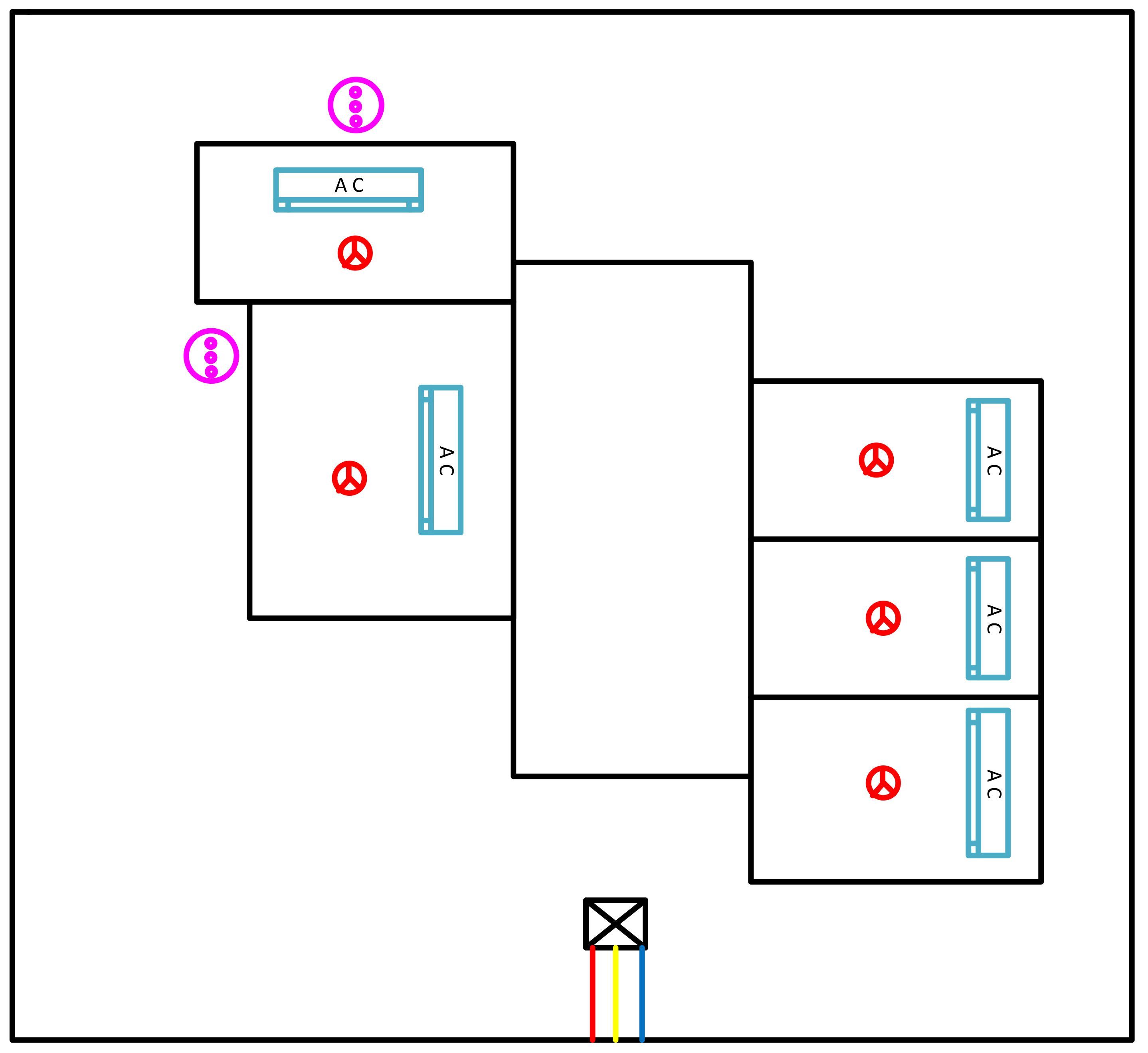
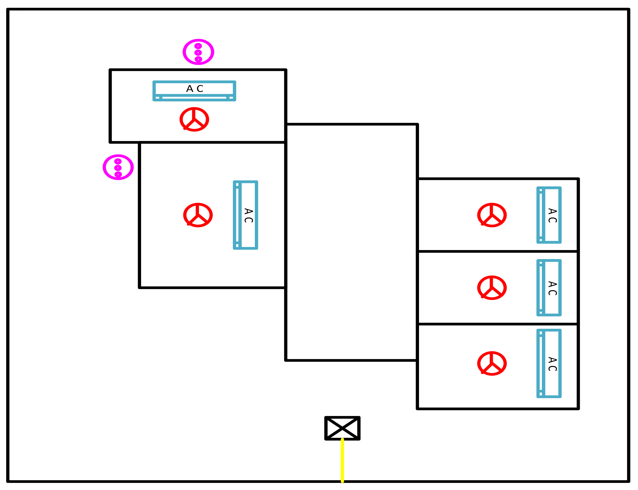
3.1.5. Sketch of the Coordinator’s House
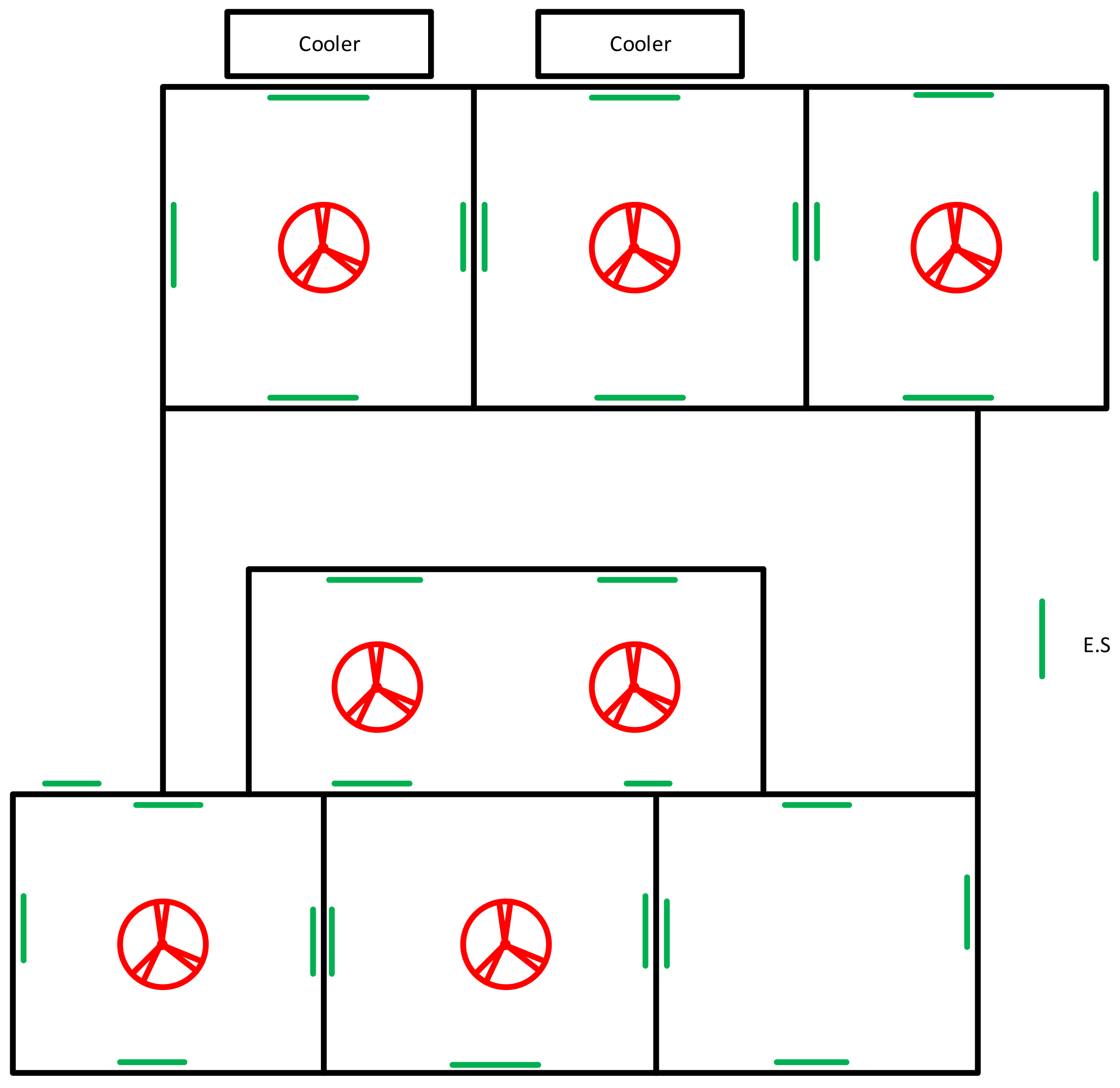
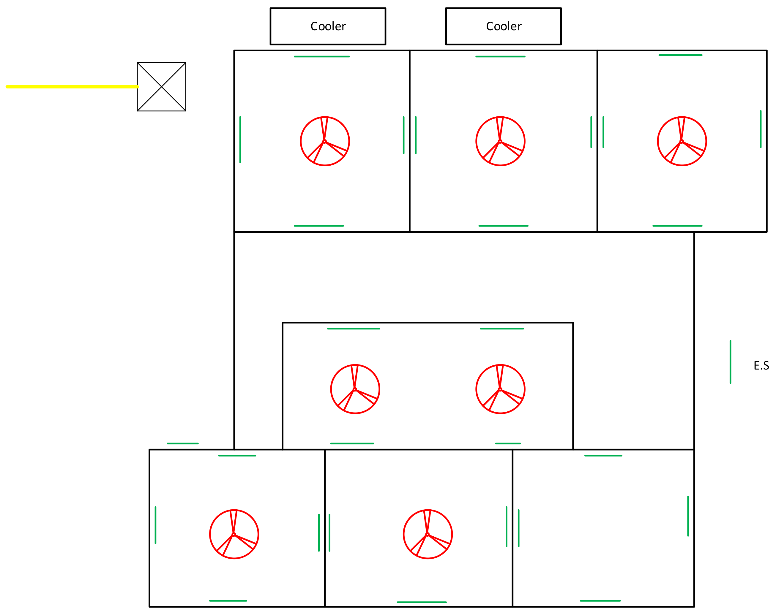
3.1.6. Sketch of the Staff Hostel
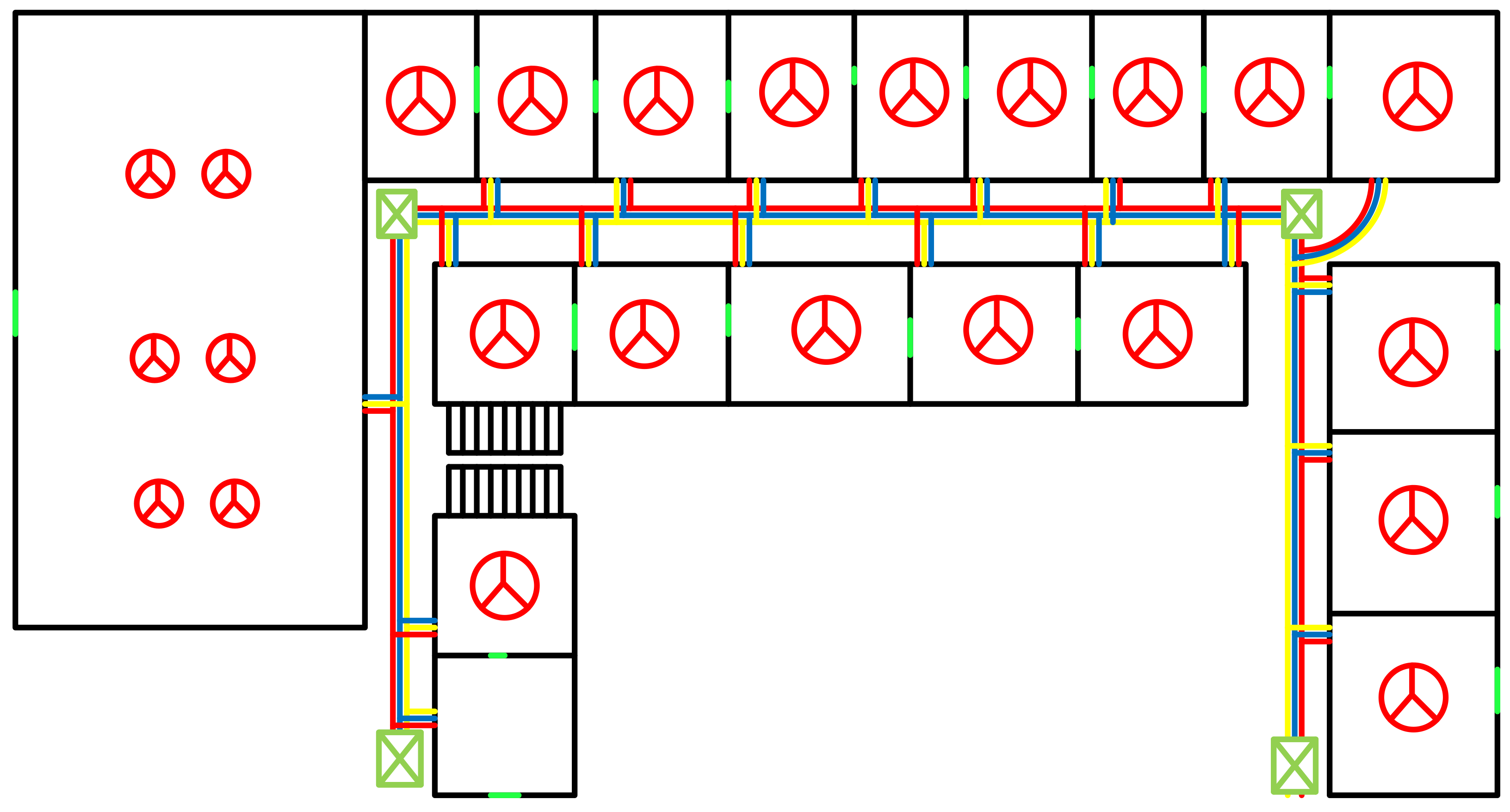
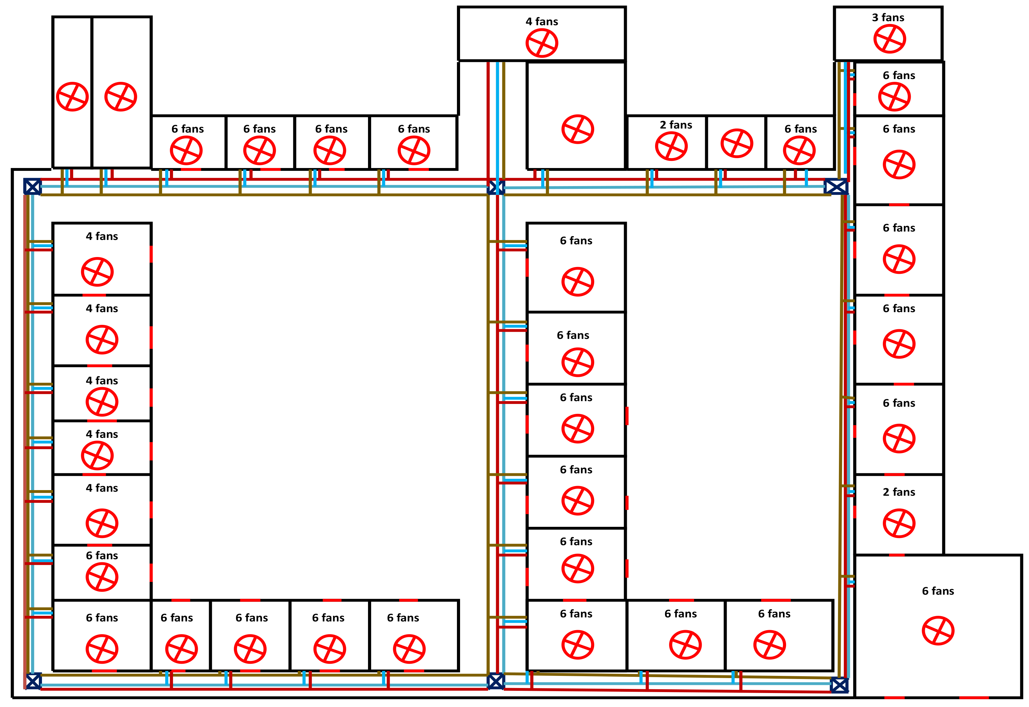
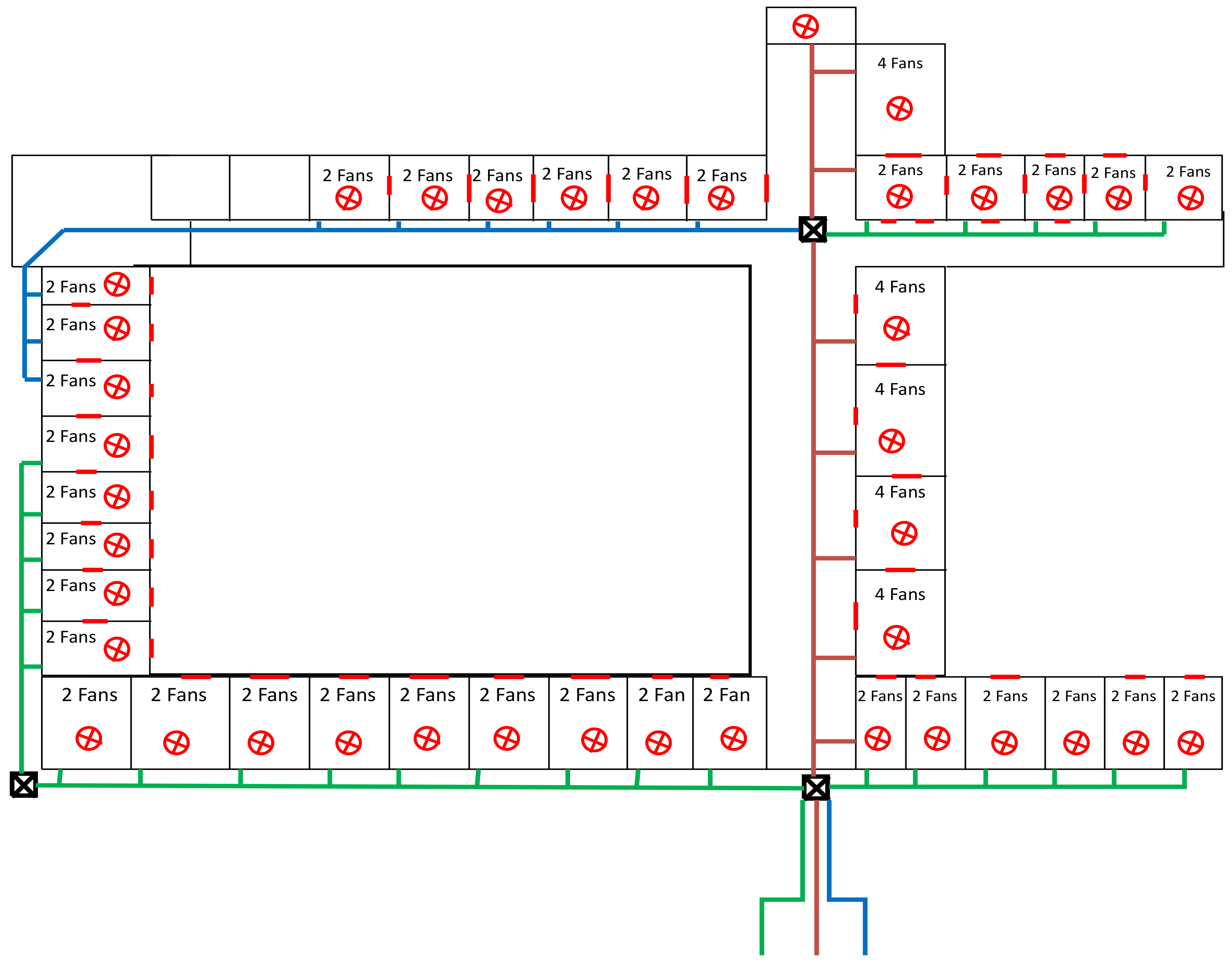
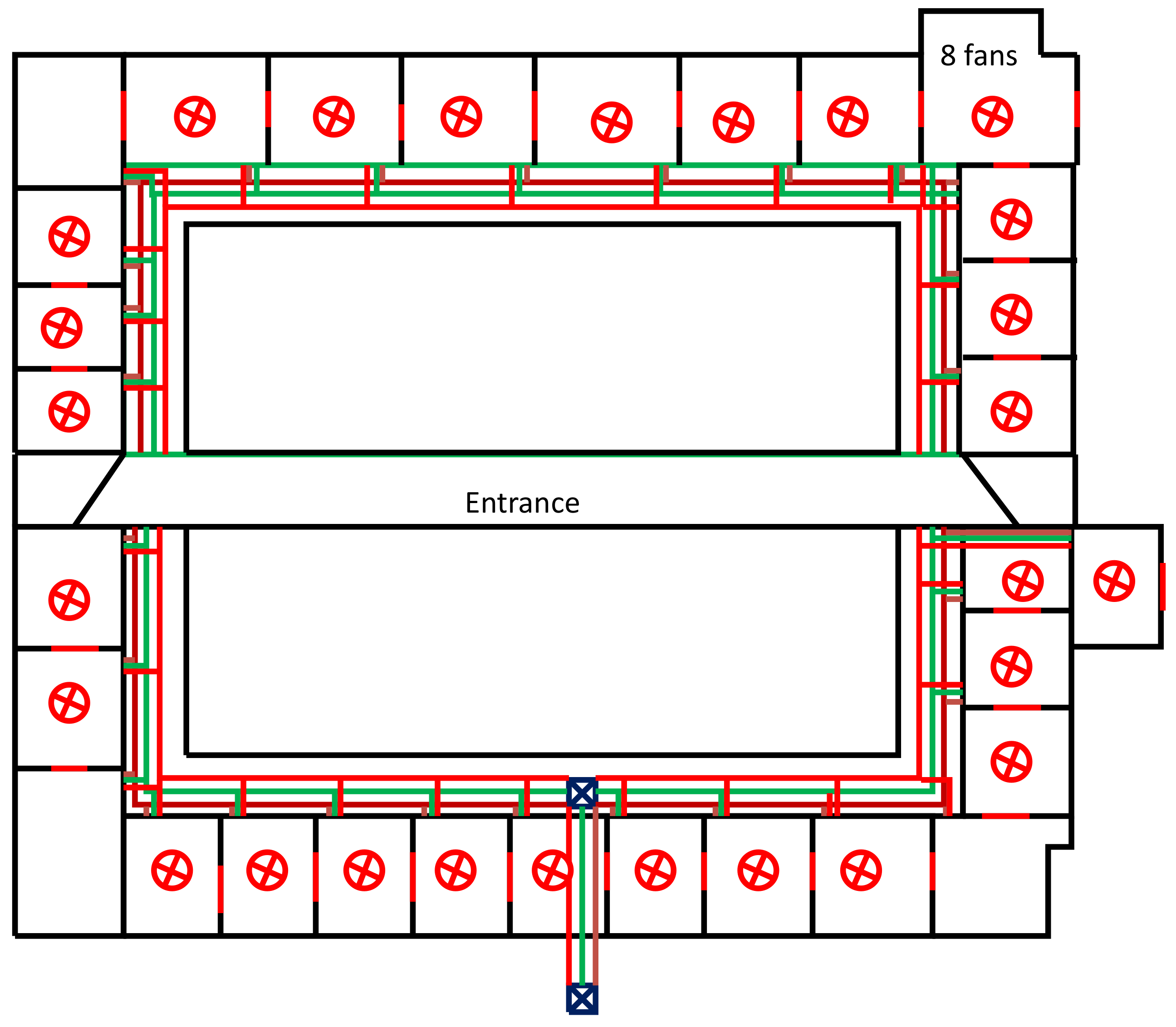
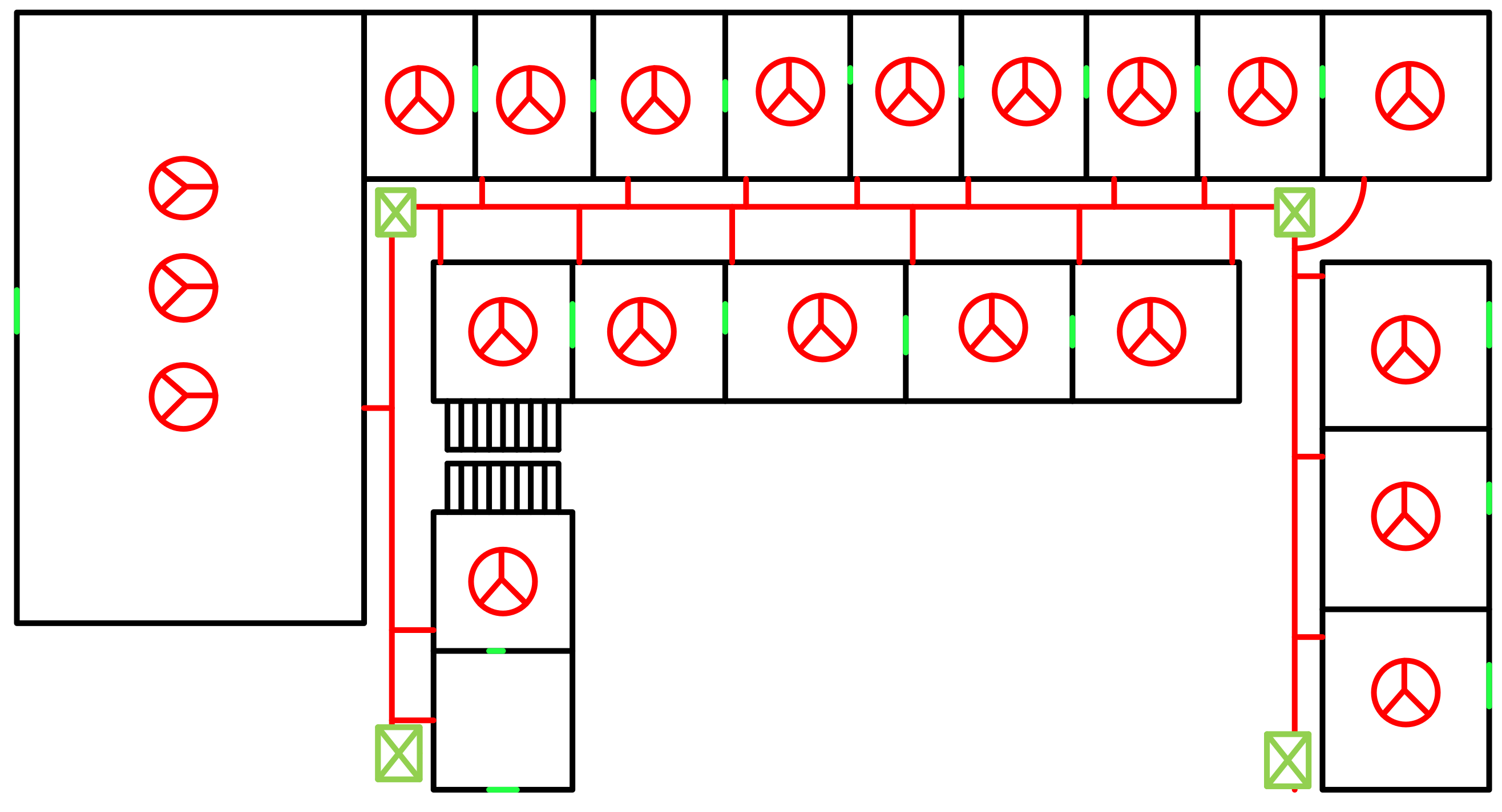
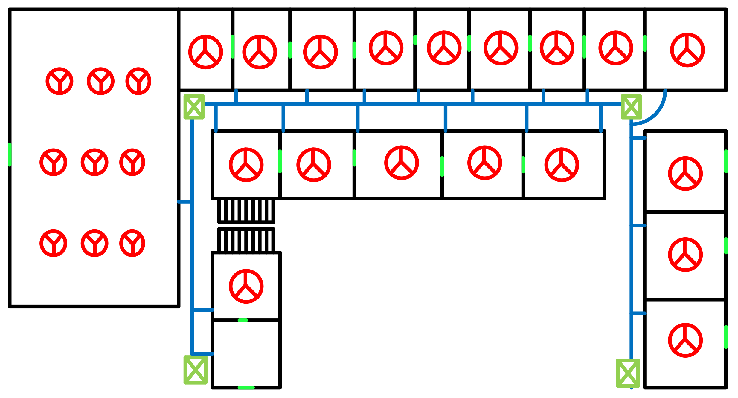
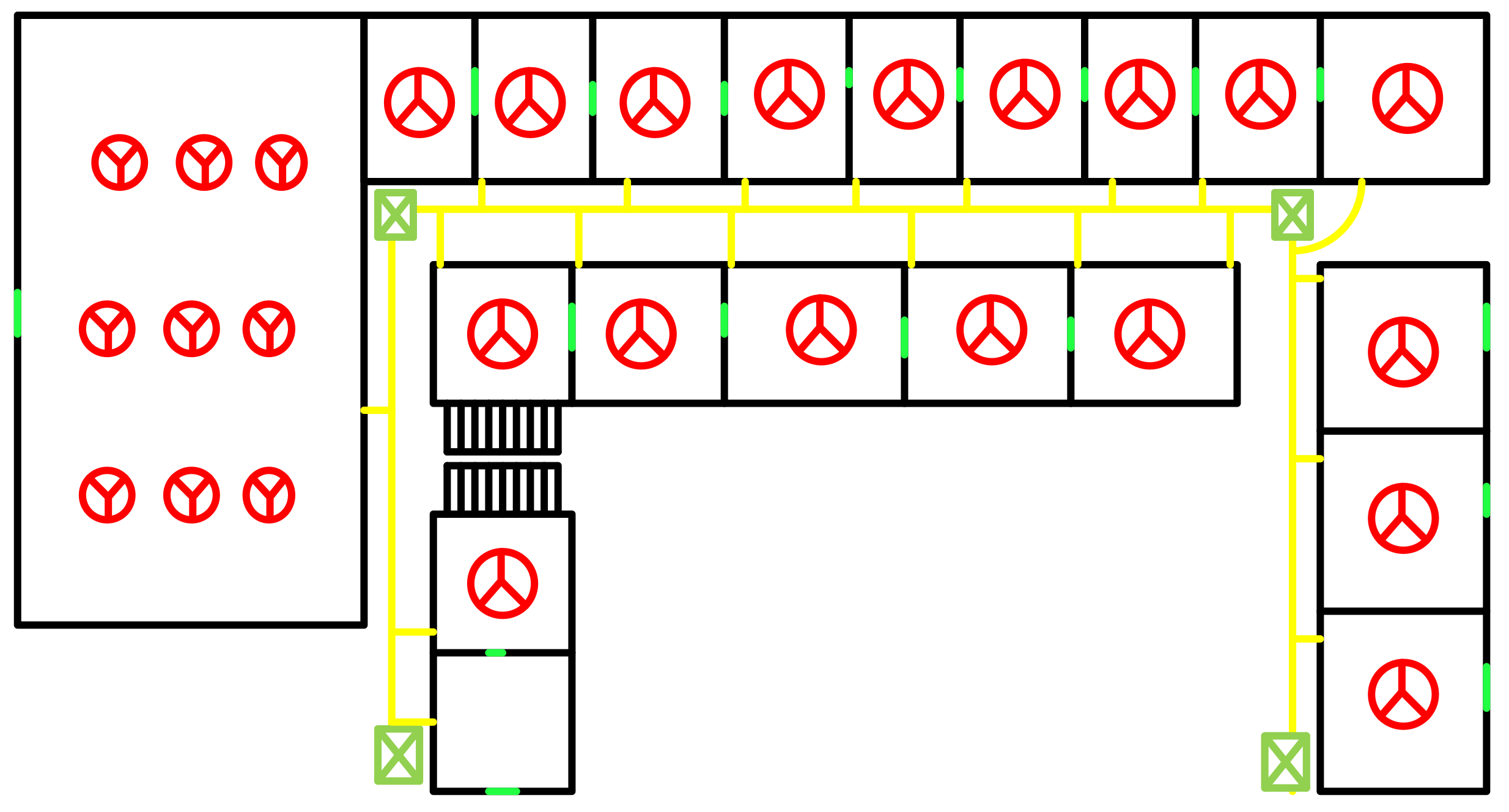
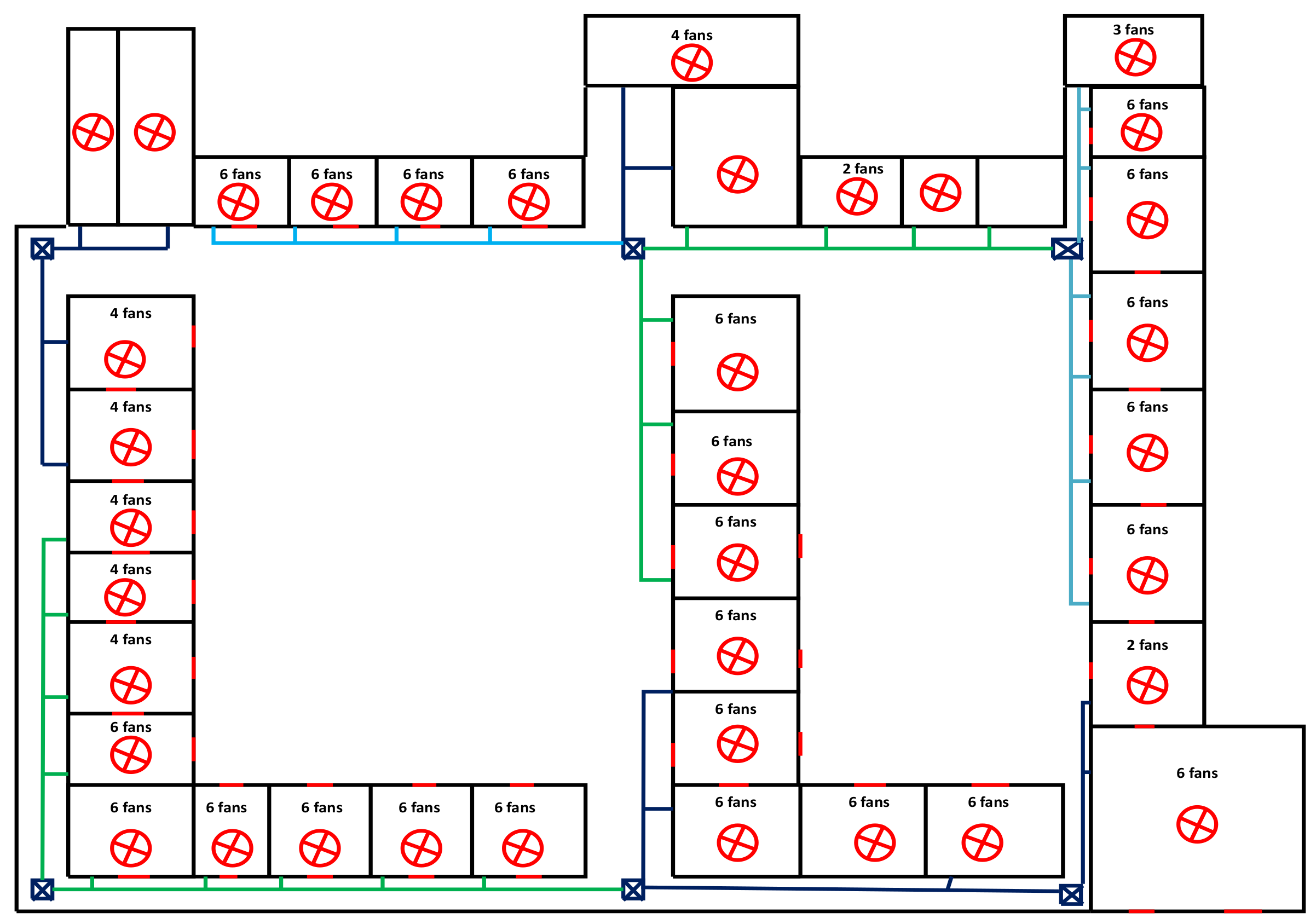
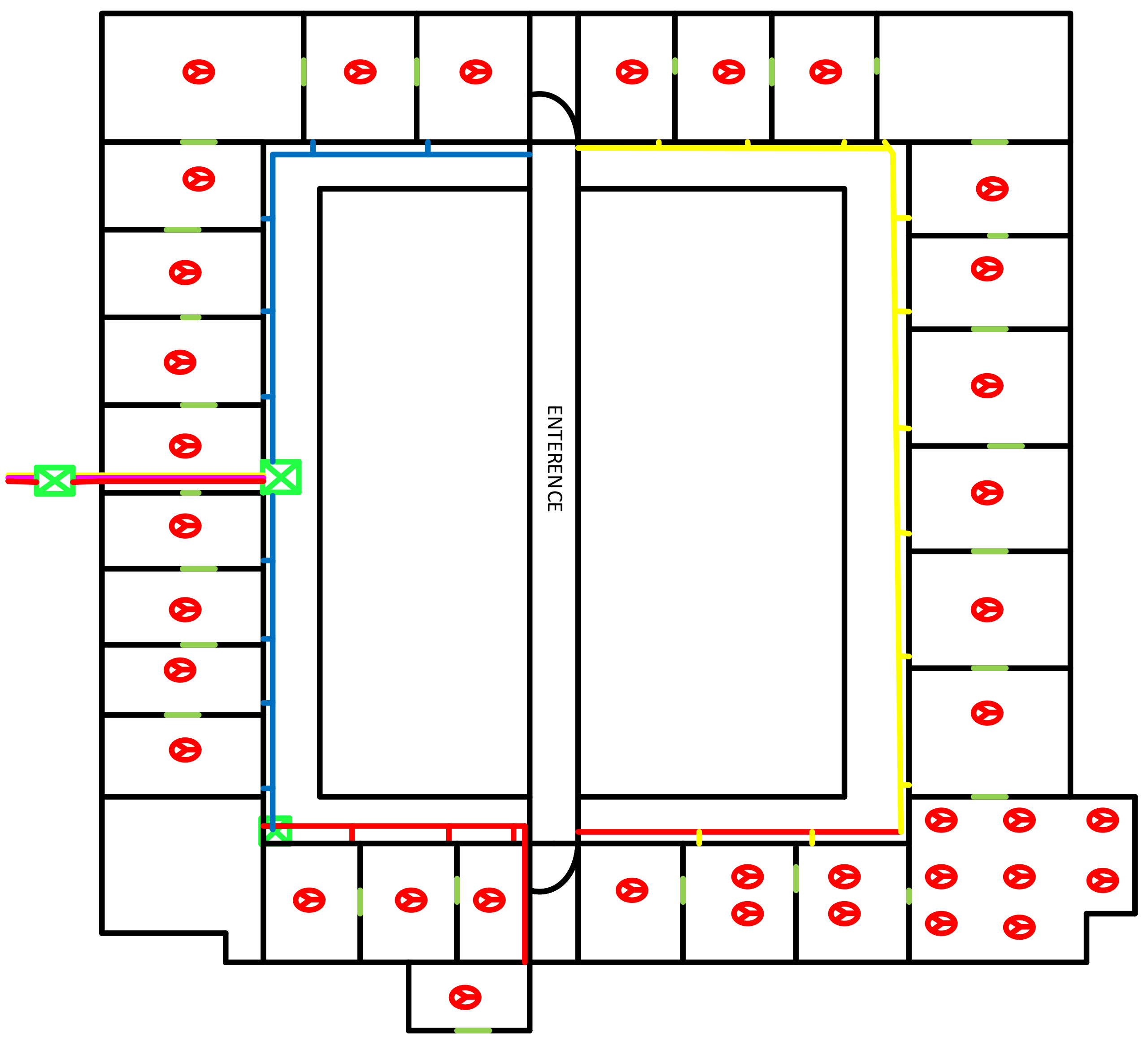
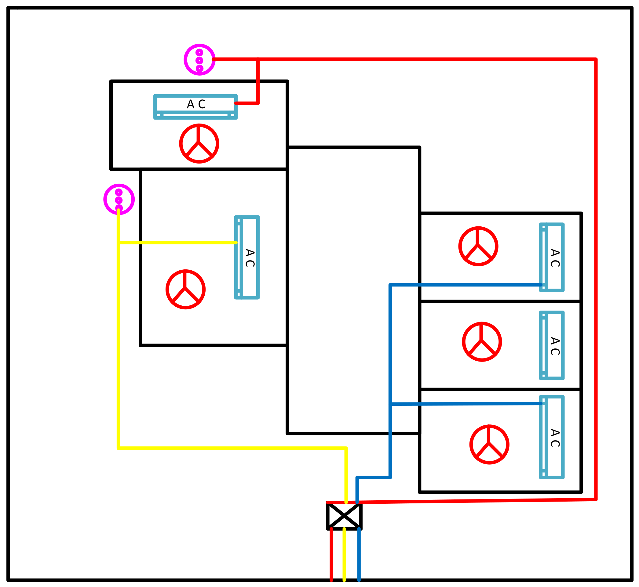
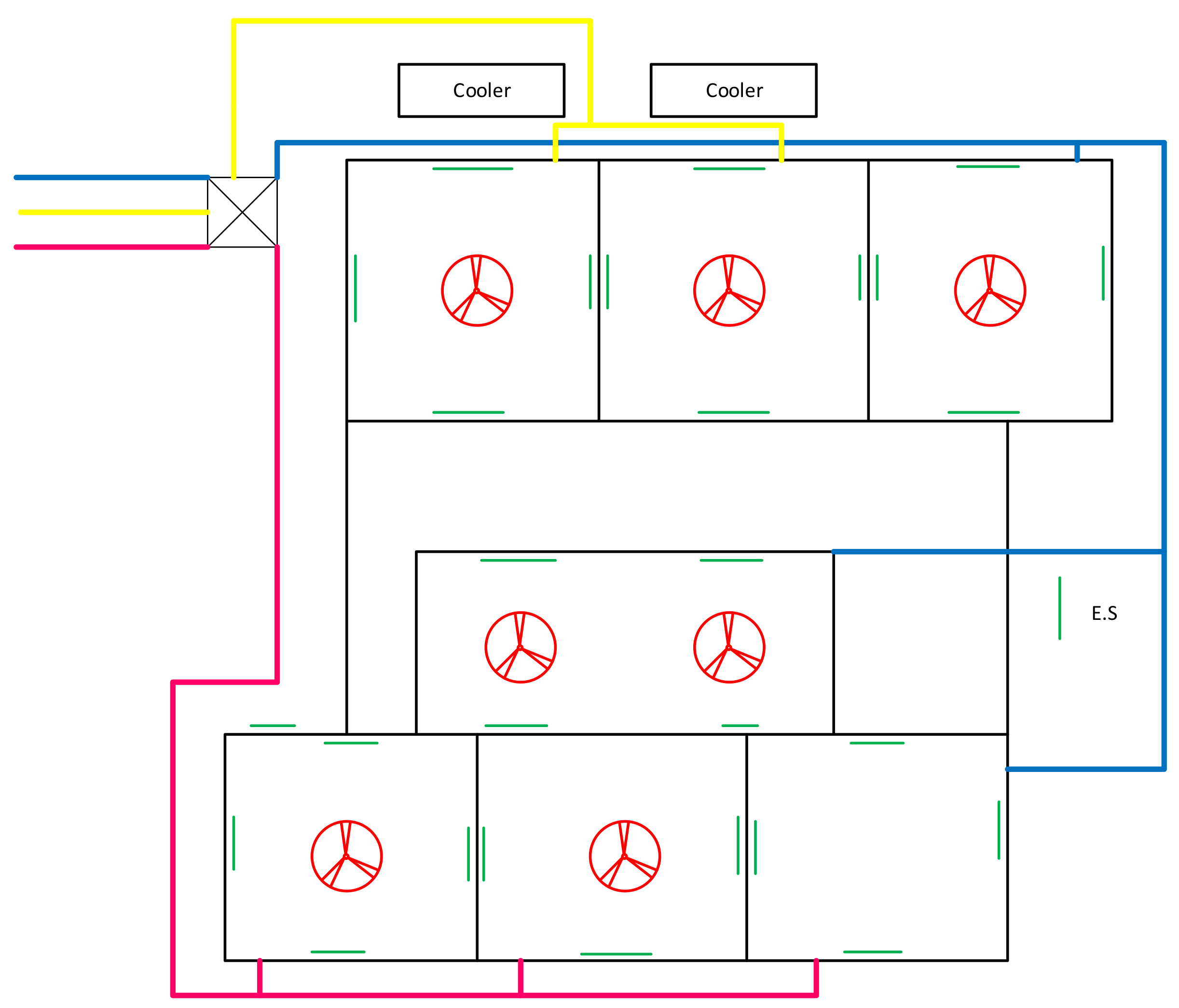
3.2. Sketches of the Existing Wiring System in Each Unit
3.2.1. Sketch of Academic Block
3.2.2. Sketch of the Allama Iqbal Hostel
3.2.3. Sketch of the Rahman Baba Hostel
3.2.4. Sketch of the Faqir API Hostel
3.2.5. Coordinator House Wiring
3.2.6. Staff Hostel Wiring
4. Proposed Nature-Inspired Moth–Flame Optimization (MFO) Algorithm
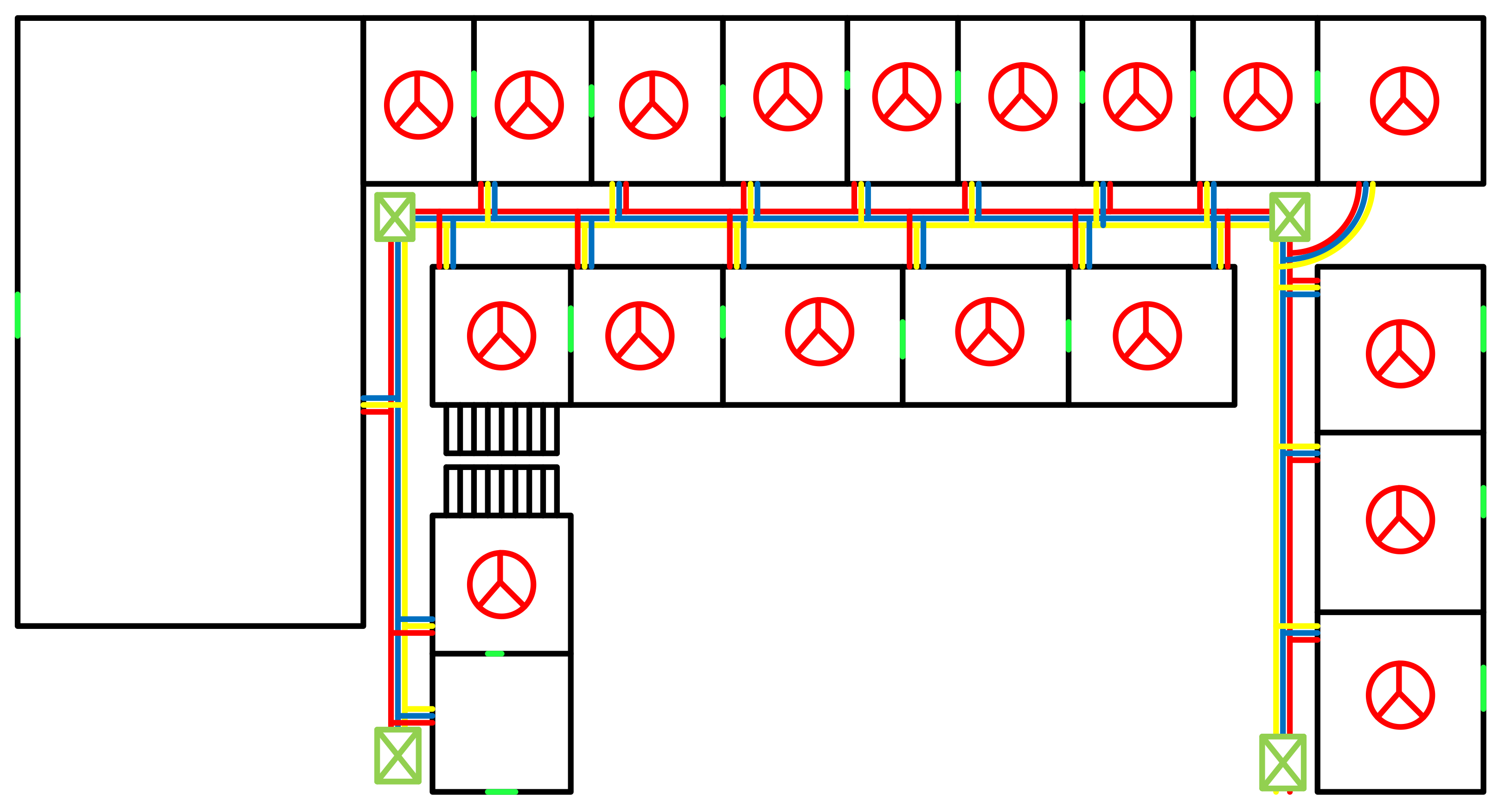
5. Proposed Model for Balance Load
5.1. The Proposed Model for an Academic Block
5.2. The Proposed Model for the Rahman Baba Hostel
5.3. The Proposed Model for the Faqir API Hostel
5.4. The Proposed Model for the Coordinator House
5.5. The Proposed Model for the Staff Hostel
6. Results and Discussion
6.1. Allama Iqbal Hostel
6.2. Rahman Baba Hostel
Academic Block
6.3. Coordinator House
6.4. Staff Hostel
6.5. Cost Estimation
7. Conclusions and Future Work
Author Contributions
Funding
Institutional Review Board Statement
Informed Consent Statement
Data Availability Statement
Acknowledgments
Conflicts of Interest
References
- Siti, M.W.; Nicolae, D.V.; Jimoh, A.A.; Ukil, A. Reconfiguration and load balancing in the LV and MV distribution networks for optimal performance. IEEE Trans. Power Deliv. 2007, 22, 2534–2540. [Google Scholar] [CrossRef]
- Homaee, O.; Najafi, A.; Dehghanian, M.; Attar, M.; Falaghi, H. A practical approach for distribution network load balancing by optimal re-phasing of single phase customers using discrete genetic algorithm. Int. Trans. Electr. Energy Syst. 2019, 29, e2834. [Google Scholar] [CrossRef]
- Hussain, I.; Ullah, M.; Ullah, I.; Bibi, A.; Naeem, M.; Singh, M.; Singh, D. Optimizing energy consumption in the home energy management system via a bio-inspired dragonfly algorithm and the genetic algorithm. Electronics 2020, 9, 406. [Google Scholar] [CrossRef]
- Hussain, I.; Ullah, I.; Ali, W.; Muhammad, G.; Ali, Z. Exploiting lion optimization algorithm for sustainable energy management system in industrial applications. Sustain. Energy Technol. Assess. 2022, 52, 102237. [Google Scholar] [CrossRef]
- Kaveh, M.R.; Hooshmand, R.A.; Madani, S.M. Simultaneous optimization of re-phasing, reconfiguration and DG placement in distribution networks using BF-SD algorithm. Appl. Soft Comput. 2018, 62, 1044–1055. [Google Scholar] [CrossRef]
- Riaz, M.; Ahmad, S.; Hussain, I.; Naeem, M.; Mihet-Popa, L. Probabilistic Optimization Techniques in Smart Power System. Energies 2022, 15, 825. [Google Scholar] [CrossRef]
- Carvalho, P.M.; Ferreira, L.A.; Santana, J.J.; Dias, A.M.; Machado, J.A. Combined effects of load variability and phase imbalance onto simulated LV losses. IEEE Trans. Power Syst. 2018, 33, 7031–7041. [Google Scholar] [CrossRef]
- Ullah, I.; Hussain, I.; Uthansakul, P.; Riaz, M.; Khan, M.N.; Lloret, J. Exploiting multi-verse optimization and sine-cosine algorithms for energy management in smart cities. Appl. Sci. 2020, 10, 2095. [Google Scholar] [CrossRef] [Green Version]
- Kong, W.; Ma, K.; Wu, Q. Three-phase power imbalance decomposition into systematic imbalance and random imbalance. IEEE Trans. Power Syst. 2017, 33, 3001–3012. [Google Scholar] [CrossRef] [Green Version]
- Ullah, H.; Khan, M.; Hussain, I.; Ullah, I.; Uthansakul, P.; Khan, N. An Optimal Energy Management System for University Campus Using the Hybrid Firefly Lion Algorithm (FLA). Energies 2021, 14, 6028. [Google Scholar] [CrossRef]
- Grigoraș, G.; Neagu, B.C.; Gavrilaș, M.; Triștiu, I.; Bulac, C. Optimal phase load balancing in low voltage distribution networks using a smart meter data-based algorithm. Mathematics 2020, 8, 549. [Google Scholar] [CrossRef] [Green Version]
- Ullah, I.; Hussain, I.; Singh, M. Exploiting grasshopper and cuckoo search bio-inspired optimization algorithms for industrial energy management system: Smart industries. Electronics 2020, 9, 105. [Google Scholar] [CrossRef] [Green Version]
- Hussain, I.; Samara, G.; Ullah, I.; Khan, N. Encryption for End-User Privacy: A Cyber-Secure Smart Energy Management System. In Proceedings of the 2021 22nd International Arab Conference on Information Technology (ACIT), Muscat, Oman, 21–23 December 2021; pp. 1–6. [Google Scholar] [CrossRef]
- Liu, S.; Cui, X.; Lin, Z.; Lian, Z.; Lin, Z.; Wen, F.; Ding, Y.; Wang, Q.; Yang, L.; Jin, R.; et al. Practical method for mitigating three-phase unbalance based on data-driven user phase identification. IEEE Trans. Power Syst. 2020, 35, 1653–1656. [Google Scholar] [CrossRef]
- Chen, S.; Guo, Z.; Yang, Z.; Xu, Y.; Cheng, R.S. A game theoretic approach to phase balancing by plug-in electric vehicles in the smart grid. IEEE Trans. Power Syst. 2019, 35, 2232–2244. [Google Scholar] [CrossRef]
- Sun, S.; Liang, B.; Dong, M.; Taylor, J.A. Phase balancing using energy storage in power grids under uncertainty. IEEE Trans. Power Syst. 2015, 31, 3891–3903. [Google Scholar] [CrossRef] [Green Version]
- Hussain, I.; Khan, F.; Ahmad, I.; Khan, S.; Saeed, M. Power loss reduction via distributed generation system injected in a radial feeder. Mehran Univ. Res. J. Eng. Technol. 2021, 40, 160–168. [Google Scholar] [CrossRef]
- Irshad; Aamir; Ibrar; Khan, N.; Riaz, M. Reliable and Secure Advanced Metering Infrastructure for Smart Grid Network. In Proceedings of the 2018 International Conference on Computing, Electronic and Electrical Engineering (ICE Cube), Quetta, Pakistan, 12–13 November 2018; pp. 1–6. [Google Scholar] [CrossRef]
- Mirjalili, S. Moth-flame optimization algorithm: A novel nature-inspired heuristic paradigm. Knowl.-Based Syst. 2015, 89, 228–249. [Google Scholar] [CrossRef]
- Zaman, S.; Hussain, I.; Singh, D. Fast computation of integrals with fourier-type oscillator involving stationary point. Mathematics 2019, 7, 1160. [Google Scholar] [CrossRef] [Green Version]
- Zaman, S.; Khan, L.U.; Hussain, I.; Mihet-Popa, L. Fast Computation of Highly Oscillatory ODE Problems: Applications in High-Frequency Communication Circuits. Symmetry 2022, 14, 115. [Google Scholar] [CrossRef]


| Class Room | Fans | Energy Savers | Tube Light | Fan Small | Extras | Fans Rating (A) | E. Saver (A) | T.L Rating (A) | Fans Rating (A) | Extras (A) | Single Room T. Load (A) |
|---|---|---|---|---|---|---|---|---|---|---|---|
| 1 | 6 | 7 | 1 | 2.608695652 | 0 | 1.52173913 | 0 | 0.163043478 | 4.293478261 | ||
| 2 | 6 | 8 | 1 | 2.608695652 | 0 | 1.73913043 | 0 | 0.163043478 | 4.293478261 | ||
| 3 | 6 | 8 | 1 | 2.608695652 | 0 | 1.73913043 | 0 | 0.163043478 | 4.293478261 | ||
| 4 | 6 | 8 | 1 | 2.608695652 | 0 | 1.73913043 | 0 | 0.163043478 | 4.293478261 | ||
| 5 | 6 | 7 | 1 | 2.608695652 | 0 | 1.73913043 | 0 | 0.163043478 | 4.293478261 | ||
| 6 | 6 | 8 | 1 | 2.608695652 | 0 | 1.73913043 | 0 | 0.163043478 | 4.293478261 | ||
| 7 | 6 | 8 | 1 | 2.608695652 | 0 | 1.73913043 | 0 | 0.163043478 | 4.293478261 | ||
| 8 | 6 | 8 | 1 | 2.608695652 | 0 | 1.73913043 | 0 | 0.163043478 | 4.293478261 | ||
| lab.1 | 4 | 2 | 5 | 1 | 0 | 0.434782609 | 0.43478261 | 1.630434783 | 0.163043478 | 2.663043478 | |
| lab.2 | 8 | 4 | 7 | 1 | 0 | 0.869565217 | 0.869569522 | 2.282608696 | 0.163043478 | 4.184782608 | |
| faculty office | 5 | 2 | 2 | 2.608695652 | 0.217391304 | 0.434778261 | 0 | 0 | 2.663043478 | ||
| R & D lab | 5 | 6 | 3 | 0 | 0.543478261 | 0 | 1.956521739 | 0.489130435 | 2.663043478 | ||
| lab.3 | 4 | 6 | 1 | 0 | 0.434782609 | 0 | 1.956521739 | 0.163043478 | 2.663043478 | ||
| lab.4 | 4 | 6 | 1 | 0 | 0.434782609 | 0 | 1.956521739 | 0.163043478 | 2.663043478 | ||
| confrence | 2 | 2 | 0 | 0.217391304 | 0 | 0.652173913 | 0 | 0.869565217 | |||
| Account sec. | 4 | 9 | 1 | 1 | 1.739130435 | 0.97826087 | 0.2173913 | 0.326086958 | 0 | 3.260869565 | |
| Main Hall | 17 | 24 | 0 | 0 | 3.69565217 | 7.826086957 | 0 | 11.52173913 | |||
| office | 1 | 2 | 1 | 0.434782609 | 0.217391304 | 0 | 0 | 0 | 0.652173913 | ||
| Chairman CED | 1 | 1 | 10 | 3 | 1 | 0.434782609 | 0.108695652 | 2.17391304 | 0.97826087 | 0.163043478 | 3.858695652 |
| Coordinator | 11 | 4 | 0 | 1.195652174 | 0 | 1.304347826 | 0 | 2.5 | |||
| Chairman EED | 4 | 2 | 4 | 1 | 0 | 0.434782609 | 0.43478261 | 1.304347826 | 0.163043478 | 2.336956522 | |
| Sem. Coordinator | 2 | 2 | 0 | 0 | 0.43478261 | 0.652173913 | 0 | 1.086956522 | |||
| BSI | 4 | 2 | 1.739130435 | 0 | 0.43478261 | 0 | 0 | 2.173913043 | |||
| ADS | 2 | 6 | 0.869565217 | 0 | 1.30434783 | 0 | 0 | 2.173913043 | |||
| Library | 37 | 3 | 13 | 1 | 0 | 4.0.2173913 | 0.65217391 | 4.239130435 | 0.163043478 | 9.076086957 | |
| Matrial Lab | 4 | 4 | 2 | 1.739130435 | 0.434782609 | 0.43478261 | 0 | 0 | 2.608695652 | ||
| Exam Section | 2 | 2 | 0.869565217 | 217391304 | 0 | 0 | 0 | 1.086956522 | |||
| Servey lab | 1 | 3 | 0.434782609 | 0.326086957 | 0 | 0 | 0 | 0.760869565 | |||
| Lavatory | 1 | 0.434782609 | 0 | 0 | 0 | 0 | 0.434782609 | ||||
| Hydrulaic Lab | 3 | 2 | 1 | 1.304347826 | 0.217391304 | 0 | 0 | 0.163043478 | 1.684782609 | ||
| Envir. Lab | 3 | 4 | 1 | 1.304347826 | 0.434782609 | 0 | 0 | 0.163043478 | 1.902173913 | ||
| Concrete Lab | 6 | 6 | 1 | 2.608695652 | 0.652173913 | 0 | 0 | 0.163043478 | 3.423913043 | ||
| Highway lab | 2 | 4 | 1 | 1 | 0.869565217 | 0.434782609 | 0.2173913 | 0 | 0.163043478 | 1.684782609 | |
| Workshop lab | 5 | 3 | 1 | 2.173913043 | 0.326086957 | 0 | 0 | 0.163043478 | 2.663043478 | ||
| Control sys lab | 6 | 6 | 1 | 2.608695652 | 652173913 | 0 | 0 | 0.163043478 | 3.423913043 | ||
| Small room | 2 | 2 | 0.869565217 | 0.217391304 | 0 | 0 | 0 | 1.086956522 | |||
| Canteen | 6 | 10 | 2.608695652 | 1.086956522 | 0 | 0 | 0 | 3.69562174 | |||
| Bathroom | 1 | 1 | 0 | 0.108695652 | 0.2173913 | 0 | 0 | 0.326086957 | |||
| farooq room | 2 | 2 | 0.869565217 | 0.217391304 | 0 | 0 | 0 | 1.086956522 | |||
| Small room | 2 | 2 | 0.869565217 | 0.217391304 | 0 | 0 | 0 | 1.086956522 | |||
| Common. Lab | 4 | 3 | 4 | 1 | 1.739130435 | 0.326086957 | 0.86956522 | 0 | 0.163043478 | 3.097822609 | |
| DLD lab | 4 | 4 | 1.739130435 | 0.434782609 | 0 | 0 | 0 | 2.173913043 | |||
| Machine Lab | 4 | 4 | 1 | 1.739130435 | 0.434782609 | 0 | 0 | 0.163043478 | 2.336956522 | ||
| ElectronicS Lab | 4 | 7 | 2 | 1.739130435 | 0.760869565 | 0 | 0 | 0.326086957 | 2.826086957 | ||
| GRAND TOTAL | 17.60869565 | 130.326087 |
| Room No. 01 | Fans | Energy Saver | Tube Light | Geyser | E. Saver Rating (A) | Fans Rating (A) | Tube Light Rating (A) | Gyser Rating (A) | Load in Single Room (A) |
|---|---|---|---|---|---|---|---|---|---|
| 1 | 1 | 4 | 0.43478 | 0.43478 | 0 | 0 | 0.86597 | ||
| 2 | 1 | 2 | 0.21739 | 0.43478 | 0 | 0 | 0.86597 | ||
| 3 | 1 | 2 | 0.21739 | 0.43478 | 0 | 0 | 0.86597 | ||
| 4 | 1 | 2 | 0.21739 | 0.43478 | 0 | 0 | 0.86597 | ||
| 5 | 1 | 1 | 0.1087 | 0.43478 | 0 | 0 | 0.86597 | ||
| 6 | 1 | 2 | 0.21739 | 0.43478 | 0 | 0 | 0.86597 | ||
| 7 | 1 | 2 | 0.21739 | 0.43478 | 0 | 0 | 0.86597 | ||
| 8 | 1 | 3 | 0.32609 | 0.43478 | 0 | 0 | 0.86597 | ||
| 9 | 1 | 1 | 0.1087 | 0.43478 | 0 | 0 | 0.86597 | ||
| 10 | 1 | 2 | 0.21739 | 0.43478 | 0 | 0 | 0.86597 | ||
| 11 | 1 | 2 | 0.21739 | 0.43478 | 0 | 0 | 0.86597 | ||
| 12 | 1 | 1 | 1 | 0.1087 | 0.43478 | 0.21739 | 0 | 0.86597 | |
| 13 | 1 | 3 | 0.32609 | 0.43478 | 0 | 0 | 0.86597 | ||
| 14 | 1 | 1 | 0.1087 | 0.43478 | 0 | 0 | 0.86597 | ||
| 15 | 1 | 2 | 0.21739 | 0.43478 | 0 | 0 | 0.86597 | ||
| 16 | 1 | 2 | 0.21739 | 0.43478 | 0 | 0 | 0.86597 | ||
| 17 | 1 | 2 | 0.21739 | 0.43478 | 0 | 0 | 0.86597 | ||
| 18 | 1 | 1 | 0.1087 | 0.43478 | 0 | 0 | 0.86597 | ||
| 19 | 1 | 2 | 0.21739 | 0.43478 | 0 | 0 | 0.86597 | ||
| 20 | 1 | 1 | 0.1087 | 0.43478 | 0 | 0 | 0.86597 | ||
| 21 | 1 | 3 | 0.32609 | 0.43478 | 0 | 0 | 0.86597 | ||
| 22 | 1 | 1 | 1 | 0.1087 | 0.43478 | 0.21739 | 0 | 0.86597 | |
| 23 | 1 | 1 | 1 | 0.1087 | 0.43478 | 0.21739 | 0 | 0.86597 | |
| 24 | 1 | 1 | 2 | 0.1087 | 0.43478 | 0.21739 | 0 | 0.86597 | |
| 25 | 1 | 1 | 1 | 0.1087 | 0.43478 | 0.21739 | 0 | 0.86597 | |
| 26 | 1 | 3 | 0.32609 | 0.43478 | 0 | 0 | 0.86597 | ||
| 27 | 1 | 2 | 0.21739 | 0.43478 | 0 | 0 | 0.86597 | ||
| Staff room. 01 | 2 | 2 | 0 | 0.86957 | 0.43478 | 0 | 0.86597 | ||
| Staff room. 02 | 2 | 4 | 0.43478 | 0.86957 | 0 | 0 | 0.86597 | ||
| Staff room. 03 | 2 | 4 | 0.43478 | 0.86957 | 0 | 0 | 0.86597 | ||
| Washroom | 1 | 0.1087 | 0 | 0 | 0 | 0.86597 | |||
| Bathroom 01 | 1 | 1 | 0.1087 | 0 | 0.21739 | 0 | 0.86597 | ||
| Bathroom 02 | 1 | 0.1087 | 0 | 0 | 0 | 0.86597 | |||
| T.V Room | 4 | 4 | 0.43478 | 1.73913 | 0 | 0 | 0.86597 | ||
| Outside | 10 | 1.08696 | 0 | 0 | 0 | 0.86597 | |||
| G. Room 01 | 2 | 2 | 0.21739 | 0.86957 | 0 | 0 | 0.86597 | ||
| G. Room 02 | 2 | 2 | 0.21739 | 0.86957 | 0 | 0 | 0.86597 | ||
| G. Room 03 | 2 | 2 | 0.21739 | 0.86957 | 0 | 0 | 0.86597 | ||
| Wash Room | 2 | 1 | 0.21739 | 0 | 0 | 10 | 0.86597 | ||
| Kitchen | 2 | 0.1087 | 0 | 0 | 0 | 0.86597 | |||
| OUTSIDE | 15 | 1.63043 | 0 | 0 | 0 | 0.86597 | |||
| Grand Total | 35.50477 |
| Room No. | Fans | Energy Savers | Energy Saver Rating (A) | Fan Rating (A) | Load in Single Room (A) |
|---|---|---|---|---|---|
| 1 | 1 | 1 | 0.108695652 | 0.434782609 | 0.543478261 |
| 2 | 1 | 1 | 0.108695652 | 0.434782609 | 0.543478261 |
| 3 | 1 | 1 | 0.108695652 | 0.434782609 | 0.543478261 |
| 4 | 1 | 1 | 0.108695652 | 0.434782609 | 0.543478261 |
| 5 | 1 | 2 | 0.217391304 | 0.434782609 | 0.652173913 |
| 6 | 1 | 1 | 0.108695652 | 0.434782609 | 0.543478261 |
| 7 | 1 | 2 | 0.217391304 | 0.434782609 | 0.652173913 |
| 8 | 1 | 2 | 0.217391304 | 0.434782609 | 0.652173913 |
| 9 | 1 | 1 | 0.108695652 | 0.434782609 | 0.543478261 |
| 10 | 1 | 2 | 0.217391304 | 0.434782609 | 0.652173913 |
| 10 | 1 | 2 | 0.217391304 | 0.434782609 | 0.652173913 |
| 11 | 1 | 2 | 0.217391304 | 0.434782609 | 0.652173913 |
| 12 | 1 | 3 | 0.326086956 | 0.434782609 | 0.760869565 |
| 13 | 1 | 3 | 0.326086956 | 0.434782609 | 0.760869565 |
| 14 | 1 | 2 | 0.217391304 | 0.434782609 | 0.652173913 |
| 15 | 1 | 5 | 0.54347826 | 0.434782609 | 0.978260869 |
| 16 | 1 | 8 | 0.869565216 | 0.434782609 | 1.304347825 |
| 17 | 1 | 1 | 0.108695652 | 0.434782609 | 0.543478261 |
| 18 | 1 | 1 | 0.108695652 | 0.434782609 | 0.543478261 |
| 19 | 1 | 1 | 0.108695652 | 0.434782609 | 0.543478261 |
| 20 | 1 | 3 | 0.326086956 | 0.434782609 | 0.760869565 |
| 21 | 1 | 1 | 0.108695652 | 0.434782609 | 0.543478261 |
| 23 | 1 | 1 | 0.108695652 | 0.434782609 | 0.543478261 |
| W.Lounch | 2 | 4 | 0.434782608 | 0.869565218 | 1.304347826 |
| Mess | 8 | 12 | 1.304347824 | 3.478260872 | 4.782608696 |
| Study Room | 1 | 1 | 0.108695652 | 0.434782609 | 0.543478261 |
| Outside | 0 | 12 | 1.304347824 0 | 1.304347824 | |
| Washroom 1 | 0 | 1 | 0.108695652 | 0 | 0.108695652 |
| Washroom 2 | 0 | 1 | 0.108695652 | 0 | 0.108695652 |
| GRAND TOTAL | 23.26086956 |
| Room No. | Fans | Energy Savers | Tube Lights | Energy Saver Rating (A) | Tube Lights Rating (A) | Fan Rating (A) | Load in Single Room (A) |
|---|---|---|---|---|---|---|---|
| 1 | 1 | 1 | 0.108696 | 0 | 0.434783 | 0.543479 | |
| 2 | 1 | 2 | 1 | 0.217392 | 0.21739 | 0.434783 | 0.869565 |
| 3 | 1 | 2 | 0.217392 | 0 | 0.434783 | 0.652175 | |
| 4 | 1 | 2 | 1 | 0.217392 | 0.21739 | 0.434783 | 0.86956 |
| 5 | 1 | 1 | 0.108696 | 0 | 0.434783 | 0.543479 | |
| 6 | 1 | 2 | 0.217392 | 0 | 0.434783 | 0.652175 | |
| 7 | 1 | 1 | 0.108696 | 0 | 0.434783 | 0.543479 | |
| 8 | 1 | 2 | 0.217392 | 0 | 0.434783 | 0.652175 | |
| 9 | 1 | 1 | 0.108696 | 0 | 0.434783 | 0.543479 | |
| S 10 | 1 | 2 | 0.217392 | 0 | 0.434783 | 0.652175 | |
| 11 | 1 | 2 | 0.217392 | 0 | 0.434783 | 0.652175 | |
| 12 | 1 | 1 | 0.108696 | 0 | 0.434783 | 0.543479 | |
| 13 | 1 | 2 | 1 | 0.217392 | 0.21739 | 0.434783 | 0.869565 |
| 14 | 1 | 2 | 1 | 0.217392 | 0.21739 | 0.434783 | 0.869565 |
| 15 | 1 | 2 | 0.217392 | 0 | 0.434783 | 0.652175 | |
| 16 | 1 | 2 | 0.217392 | 0 | 0.434783 | 0.652175 | |
| 17 | 1 | 1 | 1 | 0.108696 | 0.21739 | 0.434783 | 0.760869 |
| W. Lounge | 1 | 1 | 2 | 0.217392 | 0 | 0.434783 | 0.652175 |
| Mess | 10 | 5 | 0.54348 | 0 | 4.34783 | 4.89131 | |
| Washroom 1 | 1 | 0.108696 | 0 | 0 | 0.108696 | ||
| Small Office | 1 | 2 | 0.217392 | 0 | 0.434783 | 0.652175 | |
| GRAND TOTAL | 17.8260696 |
| Room No. | Fans | Energy Savers | Tube Lights | E.Saver Rating (A) | Tube Lights Rating (A) | Fan Rating (A) | Load in Single Room |
|---|---|---|---|---|---|---|---|
| 18 | 1 | 1 | 0.108696 | 0 | 0.434783 | 0.543478261 | |
| 19 | 1 | 1 | 0.108696 | 0 | 0.434783 | 0.543478261 | |
| 20 | 1 | 2 | 0.217391 | 0 | 0.434783 | 0.653173913 | |
| 21 | 1 | 1 | 0.108686 | 0 | 0.434783 | 0.543478261 | |
| 22 | 1 | 2 | 0.217391 | 0 | 0.434783 | 0.652173913 | |
| 23 | 1 | 1 | 0.108696 | 0 | 0.434783 | 0.543478261 | |
| 24 | 1 | 2 | 0.217391 | 0 | 0.434783 | 0.673291521 | |
| 25 | 1 | 2 | 0.217391 | 0 | 0.434783 | 0.673291521 | |
| 26 | 1 | 1 | 0.108696 | 0 | 0.434783 | 0.543478291 | |
| 27 | 1 | 2 | 0.217391 | 0 | 0.434783 | 0.673291521 | |
| 28 | 1 | 2 | 0.217391 | 0 | 0.434783 | 0.673291521 | |
| 29 | 1 | 1 | 0.108696 | 0 | 0.434783 | 0.543478291 | |
| 30 | 1 | 1 | 0.108696 | 0 | 0.434783 | 0.543478291 | |
| 31 | 1 | 2 | 0.217391 | 0 | 0.434783 | 0.673291521 | |
| 32 | 1 | 2 | 0.217391 | 0 | 0.434783 | 0.673291521 | |
| 33 | 1 | 1 | 1 | 0.108696 | 0.217391 | 0.434783 | 0.760869565 |
| W.Lounch 2 | 1 | 2 | 0.217391 | 0 | 0.434783 | 0.652173913 | |
| Washroom 2 | 1 | 1 | 0.108696 | 0 | 0 | 0.108695652 | |
| TV Room | 1 | 5 | 0.543478 | 0 | 3.913043 | 4.456521739 | |
| GRAND TOTAL | 15 |
| Room No. | Fans | Energy Savers | Tube Lights | E.Saver Rating (A) | Tube Lights Rating (A) | Fan Rating (A) | Load in Single Room |
|---|---|---|---|---|---|---|---|
| 34 | 1 | 1 | 0.108696 | 0 | 0.434783 | 0.543478261 | |
| 35 | 1 | 2 | 0.217391 | 0 | 0.434783 | 0.652173913 | |
| 36 | 1 | 2 | 0.217391 | 0 | 0.434783 | 0.652173913 | |
| 37 | 1 | 2 | 0.217391 | 0 | 0.434783 | 0.652173913 | |
| 38 | 1 | 1 | 0.108696 | 0 | 0.434783 | 0.543478261 | |
| 39 | 1 | 2 | 0.217391 | 0 | 0.434783 | 0.652173913 | |
| 40 | 1 | 2 | 0.217391 | 0 | 0.434783 | 0.652173913 | |
| 41 | 1 | 1 | 0.108696 | 0 | 0.434783 | 0.543478261 | |
| 42 | 1 | 1 | 0.108696 | 0 | 0.434783 | 0.543478261 | |
| 43 | 1 | 1 | 0.108696 | 0 | 0.434783 | 0.543478261 | |
| 44 | 1 | 1 | 0.108696 | 0 | 0.434783 | 0.543478261 | |
| 45 | 1 | 1 | 0.108696 | 0 | 0.434783 | 0.543478261 | |
| 56 | 1 | 2 | 0.2173 91 | 0 | 0.434783 | 0.652173913 | |
| 57 | 1 | 1 | 0.108696 | 0 | 0.434783 | 0.543478261 | |
| 48 | 1 | 2 | 0.217391 | 0 | 0.434783 | 0.652173913 | |
| 49 | 1 | 2 | 0.217391 | 0 | 0.434783 | 0.652173913 | |
| 50 | 1 | 2 | 0.217391 | 0 | 0.434783 | 0.652173913 | |
| Washroom 3 | 1 | 0.108696 | 0 | 0 | 0.108695652 | ||
| outside | 12 | 1.304348 | 0 | 0 | 1.304347826 | ||
| GRAND TOTAL | 11.63043478 |
| Room No. | Fans | Energy Severs | A.C (Split) | A.C (General) | Geyser | Refrigerator | E. Saver Rating (A) | Fan Rating (A) | A.C (S) Rating (A) | A.C (G) Rating | Geyser Rating | Ref.Rating | Load In Single room (A) |
|---|---|---|---|---|---|---|---|---|---|---|---|---|---|
| 1 | 1 | 4 | 1 | 1 | 0.434782609 | 0.434782609 | 6.25 | 0 | 9 | 0 | 16.11956522 | ||
| 2 | 1 | 4 | 1 | 1 | 0.434782610 | 0.434782610 | 6.26 | 0 | 9 | 0 | 16.11956522 | ||
| 3 | 1 | 4 | 1 | 0.434782611 | 0.434782611 | 6.27 | 0 | 0 | 0 | 7.119565217 | |||
| 4 | 2 | 4 | 2 | 0.434782612 | 0.869565217 | 0 | 16 | 0 | 0 | 17.30434783 | |||
| corridor | 6 | 1 | 0.652173913 | 0 | 0 | 0 | 0 2.173913043 | 2.826086957 | |||||
| washroom | 3 | 0.326086957 | 0 | 0 | 0 | 0 | 0 | 0.326086957 | |||||
| kitchen + store | 2 | 0.217391304 | 0 | 0 | 0 | 0 | 0 | 0.217391304 | |||||
| outside | 9 | 0.97826087 | 0 | 0 | 0 | 0 | 0 | 0.97826087 | |||||
| search light | 2 | 0.217391304 | 0 | 0 | 0 | 0 | 0 | 217391304 | |||||
| GRAND TOTAL | 61.22826087 |
| Room No. | Fans | Energy Saver | Cooler | Refrigrator | Fan Rating (A) | E. Saver Rating (A) | Cooler Rating (A) | Ref.Rating (A) | Load in Single Room (A) |
|---|---|---|---|---|---|---|---|---|---|
| 1 | 1 | 4 | 1 | 0.434782609 | 0.434782609 | 1.793478261 | 0 | 0.663043478 | |
| 2 | 1 | 4 | 1 | 0.434782610 | 0.434782610 | 1.793478262 | 0 | 0.663043479 | |
| 3 | 1 | 4 | 0.434782611 | 0.434782611 | 0 | 0 | 0.869565217 | ||
| 4 | 1 | 4 | 0.434782612 | 0.434782612 | 0 | 0 | 0.869565218 | ||
| 5 | 1 | 4 | 0.434782613 | 0.434782613 | 0 | 0 | 0.869565219 | ||
| Kitchen | 2 | 0 | 217391304 | 0 | 0 | 0.217391304 | |||
| outside | 4 | 0 | 0.434782609 | 0 | 0 | 0.434782609 | |||
| inside | 9 | 0 | 0.97826087 | 0 | 2.173913043 | 3.152173913 | |||
| Grand TOTAL | 11.73913043 |
| S. No. | Parameter | Value |
|---|---|---|
| 1 | Number of moths and flames | 12 |
| 2 | Max. No. of Iterations | 1000 |
| 3 | Lower bound | −100 |
| 4 | Upper bound | 100 |
| Device Name | Watt | Volt | Amp | Pf | Phase | Amp XN | Amp YN | Amp ZN | Amp N |
|---|---|---|---|---|---|---|---|---|---|
| fan | 80 W | 231 | 0.43 A | −8 | Z-N | 0.4 A | 0.4 A | ||
| fan | 80 W | 231 | 0.43 A | −8 | Y-N | 0.4 A | 0.4 A | ||
| fan | 80 W | 231 | 0.43 A | −8 | X-N | 0.4 A | 0.4 A | ||
| tube light | 40 W | 231 | 0.22 A | −8 | Z-N | 0.2A | 0.2 A | ||
| tube light | 40 W | 231 | 0.22 A | −8 | Y-N | 0.2 A | 0.2 A | ||
| tube light | 40 W | 231 | 0.22 A | −8 | Z-N | 0.2 A | 0.2 A | ||
| tube light | 40 W | 231 | 0.22 A | −8 | Y-N | 0.2 A | 0.2 A | ||
| tube light | 40 W | 231 | 0.22 A | −8 | X-N | 0.2 A | 0.2 A | ||
| tube light | 40 W | 231 | 0.22 A | −8 | Z-N | 0.2 A | 0.2 A | ||
| tube light | 40 W | 231 | 0.22 A | −8 | Y-N | 0.2 A | 0.2 A | ||
| tube light | 40 W | 231 | 0.22 A | −8 | X-N | 0.2 A | 0.2 A | ||
| tube light | 40 W | 231 | 0.22 A | −8 | Z-N | 0.2 A | 0.2 A | ||
| tube light | 40 W | 231 | 0.22 A | −8 | Y-N | 0.2 A | 0.2 A | ||
| tube light | 40 W | 231 | 0.22 A | −8 | X-N | 0.2 A | 0.2 A | ||
| tube light | 40 W | 231 | 0.22 A | −8 | Z-N | 0.2 A | 0.2 A | ||
| e saver | 25 W | 231 | 0.14 A | −8 | Y-N | 0.1 A | 0.1 A | ||
| e saver | 25 W | 231 | 0.14 A | −8 | Y-N | 0.1 A | 0.1 A | ||
| e saver | 25 W | 231 | 0.14 A | −8 | X-N | 0.1 A | 0.1 A | ||
| e saver | 25 W | 231 | 0.14 A | −8 | Z-N | 0.1 A | 0.1 A | ||
| e saver | 25 W | 231 | 0.14 A | −8 | Y-N | 0.1 A | 0.1 A | ||
| e saver | 25 W | 231 | 0.14 A | −8 | X-N | 0.1 A | 0.1 A | ||
| e saver | 25 W | 231 | 0.14 A | −8 | Z-N | 0.1 A | 0.1 A | ||
| Qty of Devices = 204 | 10,450 W | 231/400 V | 56.6 A | 3-Ph | 18.8 A | 18.9 A | 18.8 A | 0.1 A |
| Device Name | Watt | Volt | Amp | Pf | Phase | Amp XN | Amp YN | Amp ZN | Amp N |
|---|---|---|---|---|---|---|---|---|---|
| fan | 40 W | 231 | 0.43 A | −8 | X-N | 0.4 A | 0.4 A | ||
| fan | 40 W | 231 | 0.43 A | −8 | Z-N | 0.4 A | 0.4 A | ||
| fan | 40 W | 231 | 0.43 A | −8 | Y-N | 0.4 A | 0.4 A | ||
| fan | 40 W | 231 | 0.43 A | −8 | X-N | 0.4 A | 0.4 A | ||
| fan | 40 W | 231 | 0.43 A | −8 | Z-N | 0.4 A | 0.4 A | ||
| fan | 40 W | 231 | 0.43 A | −8 | Y-N | 0.4 A | 0.4 A | 0.4 A | |
| fan | 40 W | 231 | 0.43 A | −8 | X-N | 0.4 A | |||
| fan | 40 W | 231 | 0.43 A | −8 | Z-N | 0.4 A | 0.4 A | ||
| fan | 40 W | 231 | 0.43 A | −8 | Y-N | 0.4 A | 0.4 A | 0.4 A | |
| fan | 40 W | 231 | 0.43 A | −8 | X-N | 0.4 A | |||
| fan | 40 W | 231 | 0.43 A | −8 | Z-N | 0.4 A | 0.4 A | ||
| fan | 40 W | 231 | 0.43 A | −8 | Y-N | 0.4 A | 0.4 A | 0.4 A | |
| fan | 40 W | 231 | 0.43 A | −8 | X-N | 0.4 A | |||
| e saver | 25 W | 231 | 0.14 A | −8 | Z-N | 0.1 A | 0.1 A | ||
| e saver | 25 W | 231 | 0.14 A | −8 | Y-N | 0.1 A | 0.1 A | ||
| e saver | 25 W | 231 | 0.14 A | −8 | Z-N | 0.1 A | 0.1 A | ||
| e saver | 25 W | 231 | 0.14 A | −8 | Y-N | 0.1 A | 0.1 A | ||
| e saver | 25 W | 231 | 0.14 A | −8 | Z-N | 0.1 A | 0.1 A | ||
| e saver | 25 W | 231 | 0.14 A | −8 | Y-N | 0.1 A | 0.1 A | ||
| e saver | 25 W | 231 | 0.14 A | −8 | Z-N | 0.1 A | 0.1 A | ||
| e saver | 25 W | 231 | 0.14 A | −8 | Y-N | 0.1 A | 0.1 A | ||
| e saver | 25 W | 231 | 0.14 A | −8 | X-N | 0.1 A | 0.1 A | ||
| e saver | 25 W | 231 | 0.14 A | −8 | Z-N | 0.1 A | 0.1 A | ||
| QtY-N of Devices = 114 | 4720 W | 120/208 V | 25.5A | 3-Ph | 8.4 A | 8.6 A | 8.6 A | 0.1 A |
| Device Name | Watt | Volt | Amp | pf | Phase | Amp XN | Amp YN | Amp ZN | Amp N |
|---|---|---|---|---|---|---|---|---|---|
| Fan | 80 | 231 | 0.43 A | −8 | Y-N | 0.4 | 0.4 A | ||
| Fan | 80 | 232 | 0.43 A | −8 | Z-N | 0.4 | 0.4 A | ||
| Fan | 80 | 233 | 0.43 A | −8 | X-N | 0.4 | 0.4 A | ||
| Fan | 80 | 234 | 0.43 A | −8 | Y-N | 0.4 | 0.4 A | ||
| Fan | 80 | 235 | 0.43 A | −8 | Z-N | 0.4 | 0.4 A | ||
| Fan | 80 | 236 | 0.43 A | −8 | X-N | 0.4 | 0.4 A | ||
| Fan | 80 | 237 | 0.43 A | −8 | Y-N | 0.4 | 0.4 A | ||
| Fan | 80 | 238 | 0.43 A | −8 | Z-N | 0.4 | 0.4 A | ||
| Fan | 80 | 239 | 0.43 A | −8 | X-N | 0.4 | 0.4 A | ||
| Fan | 80 | 240 | 0.43 A | −8 | Y-N | 0.4 | 0.4 A | ||
| Fan | 80 | 240 | 0.43 A | −8 | Z-N | 0.4 | 0.4 A | ||
| Wall Fan | 73 | 241 | 0.4 A | −8 | X-N | 0.4 | 0.4 A | ||
| Wall Fan | 73 | 242 | 0.4 A | −8 | Y-N | 0.4 | 0.4 A | ||
| Wall Fan | 73 | 243 | 0.4 A | −8 | Z-N | 0.4 | 0.4 A | ||
| Wall Fan | 73 | 244 | 0.4 A | −8 | X-N | 0.4 | 0.4 A | ||
| Wall Fan | 73 | 245 | 0.4 A | −8 | Y-N | 0.4 | 0.4 A | ||
| Wall Fan | 73 | 246 | 0.4 A | −8 | Z-N | 0.4 | 0.4 A | ||
| Wall Fan | 73 | 247 | 0.4 A | −8 | X-N | 0.4 | 0.4 A | ||
| Wall Fan | 73 | 248 | 0.4 A | −8 | Y-N | 0.4 | 0.4 A | ||
| Wall Fan | 73 | 249 | 0.4 A | −8 | Z-N | 0.4 | 0.4 A | ||
| Wall Fan | 73 | 250 | 0.4 A | −8 | X-N | 0.4 | 0.4 A | ||
| Wall Fan | 73 | 251 | 0.4 A | −8 | Y-N | 0.4 | 0.4 A | ||
| Wall Fan | 73 | 252 | 0.4 A | −8 | Z-N | 0.4 | 0.4 A | ||
| Qty. of Device 524 | 26,174 W | 231/400 V | 141.6 A | 3-Ph | 47.4 A | 47.3 A | 47 A | 0.4 A |
| Device Name | Watt | Volt | Amp | pf | Phase | Amp XN | Amp YN | Amp ZN | Amp N |
|---|---|---|---|---|---|---|---|---|---|
| Tube light | 40 | 231 | 0.22 A | −8 | X-N | 0.2 | 0.2 A | ||
| Tube light | 40 | 232 | 0.22 A | −8 | Y-N | 0.2 | 0.2 A | ||
| Tube light | 40 | 233 | 0.22 A | −8 | Z-N | 0.2 | 0.2 A | ||
| Tube light | 40 | 234 | 0.22 A | −8 | X-N | 0.2 | 0.2 A | ||
| Tube light | 40 | 235 | 0.22 A | −8 | Y-N | 0.2 | 0.2 A | ||
| Tube light | 40 | 236 | 0.22 A | −8 | Z-N | 0.2 | 0.2 A | ||
| Tube light | 40 | 237 | 0.22 A | −8 | X-N | 0.2 | 0.2 A | ||
| Tube light | 40 | 238 | 0.22 A | −8 | Y-N | 0.2 | 0.2 A | ||
| Tube light | 40 | 239 | 0.22 A | −8 | Z-N | 0.2 | 0.2 A | ||
| Tube light | 40 | 240 | 0.22 A | −8 | X-N | 0.2 | 0.2 A | ||
| Tube light | 40 | 241 | 0.22 A | −8 | Y-N | 0.2 | 0.2 A | ||
| Tube light | 40 | 242 | 0.22 A | −8 | Z-N | 0.2 | 0.2 A | ||
| Tube light | 40 | 243 | 0.22 A | −8 | X-N | 0.2 | 0.2 A | ||
| Exaust | 36 | 244 | 0.22 A | −8 | Y-N | 0.2 | 0.2 A | ||
| Exaust | 36 | 245 | 0.22 A | −8 | Z-N | 0.2 | 0.2 A | ||
| Exaust | 36 | 246 | 0.22 A | −8 | X-N | 0.2 | 0.2 A | ||
| Exaust | 36 | 247 | 0.22 A | −8 | Y-N | 0.2 | 0.2 A | ||
| Exaust | 36 | 248 | 0.22 A | −8 | Z-N | 0.2 | 0.2 A | ||
| Exaust | 36 | 249 | 0.22 A | −8 | X-N | 0.2 | 0.2 A | ||
| Exaust | 36 | 250 | 0.22 A | −8 | Y-N | 0.2 | 0.2 A | ||
| Exaust | 36 | 251 | 0.22 A | −8 | Z-N | 0.2 | 0.2 A | ||
| Exaust | 36 | 252 | 0.22 A | −8 | X-N | 0.2 | 0.2 A | ||
| Exaust | 36 | 253 | 0.22 A | −8 | Y-N | 0.2 | 0.2 A | ||
| Qty. of Device: 524 | 26174 | 231/400V | 141.6 A | 3-Ph | 47.4 | 47.3 | 47 | 0.4 A |
| Device Name | Watt | Volt | Amp | pf | Phase | Amp XN | Amp YN | Amp ZN | Amp N |
|---|---|---|---|---|---|---|---|---|---|
| E. Saver | 25 | 231 | 0.14 A | −8 | X-N | 0.1 | 0.1 A | ||
| E. Saver | 25 | 232 | 0.14 A | −8 | Y-N | 0.1 | 0.1 A | ||
| E. Saver | 25 | 233 | 0.14 A | −8 | Z-N | 0.1 | 0.1 A | ||
| E. Saver | 25 | 234 | 0.14 A | −8 | X-N | 0.1 | 0.1 A | ||
| E. Saver | 25 | 235 | 0.14 A | −8 | Y-N | 0.1 | 0.1 A | ||
| E. Saver | 25 | 236 | 0.14 A | −8 | Z-N | 0.1 | 0.1 A | ||
| E. Saver | 25 | 237 | 0.14 A | −8 | X-N | 0.21 | 0.1 A | ||
| E. Saver | 25 | 238 | 0.14 A | −8 | Y-N | 0.1 | 0.1 A | ||
| E. Saver | 25 | 239 | 0.14 A | −8 | Z-N | 0.1 | 0.1 A | ||
| E. Saver | 25 | 240 | 0.14 A | −8 | X-N | 0.1 | 0.1 A | ||
| E. Saver | 25 | 241 | 0.14 A | −8 | Y-N | 0.1 | 0.1 A | ||
| E. Saver | 25 | 242 | 0.14 A | −8 | Z-N | 0.1 | 0.1 A | ||
| E. Saver | 25 | 243 | 0.14 A | −8 | X-N | 0.1 | 0.1 A | ||
| E. Saver | 25 | 244 | 0.14 A | −8 | Y-N | 0.1 | 0.1 A | ||
| E. Saver | 25 | 245 | 0.14 A | −8 | Z-N | 0.1 | 0.1 A | ||
| E. Saver | 25 | 246 | 0.14 A | −8 | X-N | 0.1 | 0.1 A | ||
| E. Saver | 25 | 247 | 0.14 A | −8 | Y-N | 0.1 | 0.1 A | ||
| E. Saver | 25 | 248 | 0.14 A | −8 | Z-N | 0.1 | 0.1 A | ||
| E. Saver | 25 | 249 | 0.14 A | −8 | X-N | 0.1 | 0.1 A | ||
| E. Saver | 25 | 250 | 0.14 A | −8 | Y-N | 0.1 | 0.1 A | ||
| E. Saver | 25 | 251 | 0.14 A | −8 | Z-N | 0.1 | 0.1 A | ||
| E. Saver | 25 | 252 | 0.14 A | −8 | X-N | 0.1 | 0.1 A | ||
| E. Saver | 25 | 253 | 0.14 A | −8 | Y-N | 0.1 | 0.1 A | ||
| Qty. of Device: 524 | 26174 | 231/400V | 141.6 A | 3-Ph | 47.4 | 47.3 | 47 | 0.4 A |
| Device Name | Watt | Volt | Amp | pf | Phase | Amp XN | Amp YN | Amp ZN | Amp N |
|---|---|---|---|---|---|---|---|---|---|
| Geyser | 3000 | 231 | 16.23 A | −8 | X-N | 16.2 | 16.2 A | ||
| Geyser | 3000 | 232 | 16.23 A | −8 | Y-N | 16.2 | 16.2 A | ||
| AC general | 1500 | 233 | 8.12 A | −8 | Z-N | 8.1 A | 8.1 A | ||
| AC general | 1500 | 234 | 8.12 A | −8 | X-N | 6.5 | 8.1 A | 8.1 A | |
| A.C Split | 1200 | 235 | 6.49 A | −8 | Y-N | 6.5 A | |||
| A.C Split | 1200 | 236 | 6.49 A | −8 | Z-N | 6.5 | 6.5 A | ||
| A.C Split | 1200 | 237 | 6.49 A | −8 | X-N | 2.7 | 6.5 A | 6.5 A | |
| Refrigerator | 500 | 238 | 2.71 A | −8 | Y-N | 2.7 A | |||
| Fan | 80 | 239 | 0.43 A | −8 | Z-N | 0.4 | 0.4 A | ||
| Fan | 80 | 240 | 0.43 A | −8 | X-N | 0.4 A | 0.4 A | ||
| Fan | 80 | 241 | 0.43 A | −8 | Y-N | 0.4 | 0.4 A | ||
| Fan | 80 | 242 | 0.43 A | −8 | Z-N | 0.4 A | 0.4 A | ||
| Fan | 80 | 243 | 0.43 A | −8 | X-N | 0.4 | 0.4 A | ||
| E. Saver | 38 | 244 | 0.21 A | −8 | Y-N | 0.2 A | 0.2 A | ||
| E. Saver | 38 | 245 | 0.21 A | −8 | Z-N | 0.2 A | 0.2 A | ||
| E. Saver | 38 | 246 | 0.21 A | −8 | X-N | 0.2 A | 0.2 A | ||
| E. Saver | 38 | 247 | 0.21 A | −8 | Y-N | 0.2 | 0.2 A | ||
| E. Saver | 38 | 248 | 0.21 A | −8 | Z-N | 0.2 A | 0.2 A | ||
| E. Saver | 38 | 249 | 0.21 A | −8 | X-N | 0.2 | 0.2 A | ||
| E. Saver | 38 | 250 | 0.21 A | −8 | Y-N | 0.2 A | 0.2 A | ||
| E. Saver | 38 | 251 | 0.21 A | −8 | Z-N | 0.2 | 0.2 A | ||
| E. Saver | 38 | 252 | 0.21 A | −8 | X-N | 0.2 A | 0.2 A | ||
| E. Saver | 38 | 253 | 0.21 A | −8 | Y-N | 0.2 | 0.2 A | ||
| Qty. of Device: 50 | 14906 | 120/208V | 80.7 A | 3-Ph | 26.9 | 26.9 A | 26.9 A | 0.0 A |
| Device Name | Watt | Volt | Amp | pf | Phase | Amp XN | Amp YN | Amp ZN | Amp N |
|---|---|---|---|---|---|---|---|---|---|
| Refrigerator | 500 | 231 | 2.71 A | −8 | X-N | 2.7 A | |||
| Cooler | 410 | 232 | 2.22 A | −8 | Y-N | 2.2 A | 2.2 A | ||
| Cooler | 410 | 233 | 2.22 A | −8 | Z-N | 2.2 A | 2.2 A | ||
| Fan | 80 | 234 | 0.43 A | −8 | X-N | 0.4 A | 0.4 A | ||
| Fan | 80 | 235 | 0.43 A | −8 | Y-N | 0.4 A | 0.4 A | ||
| Fan | 80 | 236 | 0.43 A | −8 | Z-N | 0.4 | 0.4 A | ||
| Fan | 80 | 237 | 0.43 A | −8 | X-N | 0.4 A | 0.4 A | ||
| Fan | 80 | 238 | 0.43 A | −8 | Y-N | 0.4 | 0.4 A | ||
| Saver | 25 | 239 | 0.14 A | −8 | Z-N | 0.1 | 0.1 A | ||
| Saver | 25 | 240 | 0.14 A | −8 | X-N | 0.1 A | 0.1 A | ||
| Saver | 25 | 241 | 0.14 A | −8 | Y-N | 0.1 | 0.1 A | ||
| Saver | 25 | 242 | 0.14 A | −8 | Z-N | 0.1 | 0.1 A | ||
| Saver | 25 | 243 | 0.14 A | −8 | X-N | 0.1 A | 0.1 A | ||
| Saver | 25 | 244 | 0.14 A | −8 | Y-N | 0.1 | 0.1 A | ||
| Saver | 25 | 245 | 0.14 A | −8 | Z-N | 0.1 | 0.1 A | ||
| Saver | 25 | 246 | 0.14 A | −8 | X-N | 0.1 A | 0.1 A | ||
| Saver | 25 | 247 | 0.14 A | −8 | Y-N | 0.1 | 0.1 A | ||
| Saver | 25 | 248 | 0.14 A | −8 | Z-N | 0.1 | 0.1 A | ||
| Saver | 25 | 249 | 0.14 A | −8 | X-N | 0.1 A | 0.1 A | ||
| Saver | 25 | 250 | 0.14 A | −8 | Y-N | 0.1 | 0.1 A | ||
| Saver | 25 | 251 | 0.14 A | −8 | Z-N | 0.1 | 0.1 A | ||
| Saver | 25 | 252 | 0.14 A | −8 | X-N | 0.1 A | 0.1 A | ||
| Saver | 25 | 253 | 0.14 A | −8 | Y-N | 0.1 | 0.1 A | ||
| Qty. of Device: 47 | 2596 | 120/208V | 14 A | 3-Ph | 4.6 | 4.7 A | 4.7 A | 0.1 A |
| Description | Size of the Cable | Length (m) | Quantity | Price/Meter (Cents) | Estimated Cost ($) | |
|---|---|---|---|---|---|---|
| 1 | Wiring Cable from the Faqir API Hostel to Staff Hostel (Generator Line) | LT line 7/0.122 | 165 | 2 2 × 165 = 330 | 115 | 379.5 |
| 2 | Wiring Cable for Faqir API Hostel | 7/0.29 | 210 | 3 3 × 210 = 630 | 48 | 302.4 |
| 3 | Wiring Cable for the Rahman Baba Hostel | 7/0.29 | 406 | 1 | 48 | 195 |
| 4 | Wiring Cable for the Allama Iqbal Hostel | 7/0.29 | 383 | 1 | 48 | 184 |
| 5 | Wiring Cable for Academic Block | 7/0.36 | 640 | 1 | 55 | 352 |
| 6 | Change over Switch and Circuit breakers for the Allama Iqbal Hostel | 4 4 × 2500 | 100 | |||
| Grand Total | 1512.9 |
Publisher’s Note: MDPI stays neutral with regard to jurisdictional claims in published maps and institutional affiliations. |
© 2022 by the authors. Licensee MDPI, Basel, Switzerland. This article is an open access article distributed under the terms and conditions of the Creative Commons Attribution (CC BY) license (https://creativecommons.org/licenses/by/4.0/).
Share and Cite
Ullah, I.; Hussain, I.; Rehman, K.; Wróblewski, P.; Lewicki, W.; Kavin, B.P. Exploiting the Moth–Flame Optimization Algorithm for Optimal Load Management of the University Campus: A Viable Approach in the Academia Sector. Energies 2022, 15, 3741. https://0-doi-org.brum.beds.ac.uk/10.3390/en15103741
Ullah I, Hussain I, Rehman K, Wróblewski P, Lewicki W, Kavin BP. Exploiting the Moth–Flame Optimization Algorithm for Optimal Load Management of the University Campus: A Viable Approach in the Academia Sector. Energies. 2022; 15(10):3741. https://0-doi-org.brum.beds.ac.uk/10.3390/en15103741
Chicago/Turabian StyleUllah, Ibrar, Irshad Hussain, Khalid Rehman, Piotr Wróblewski, Wojciech Lewicki, and Balasubramanian Prabhu Kavin. 2022. "Exploiting the Moth–Flame Optimization Algorithm for Optimal Load Management of the University Campus: A Viable Approach in the Academia Sector" Energies 15, no. 10: 3741. https://0-doi-org.brum.beds.ac.uk/10.3390/en15103741