
Choice of the Arch Yielding Support for the Preparatory Roadway Located near the Fault

 ,
,  , , , and
Abstract
:
1. Introduction
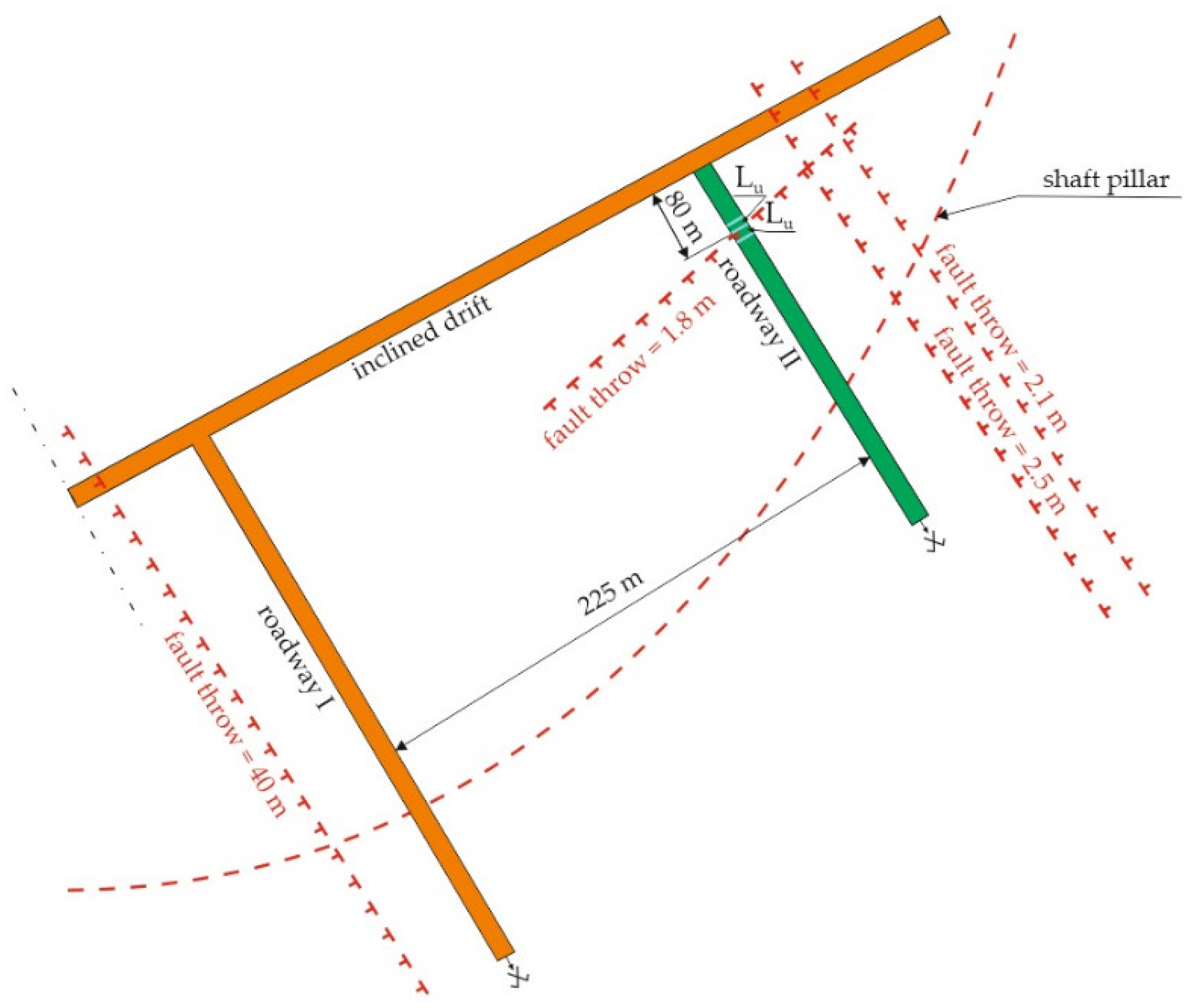
2. Mining and Geological Conditions of the Driven Excavation
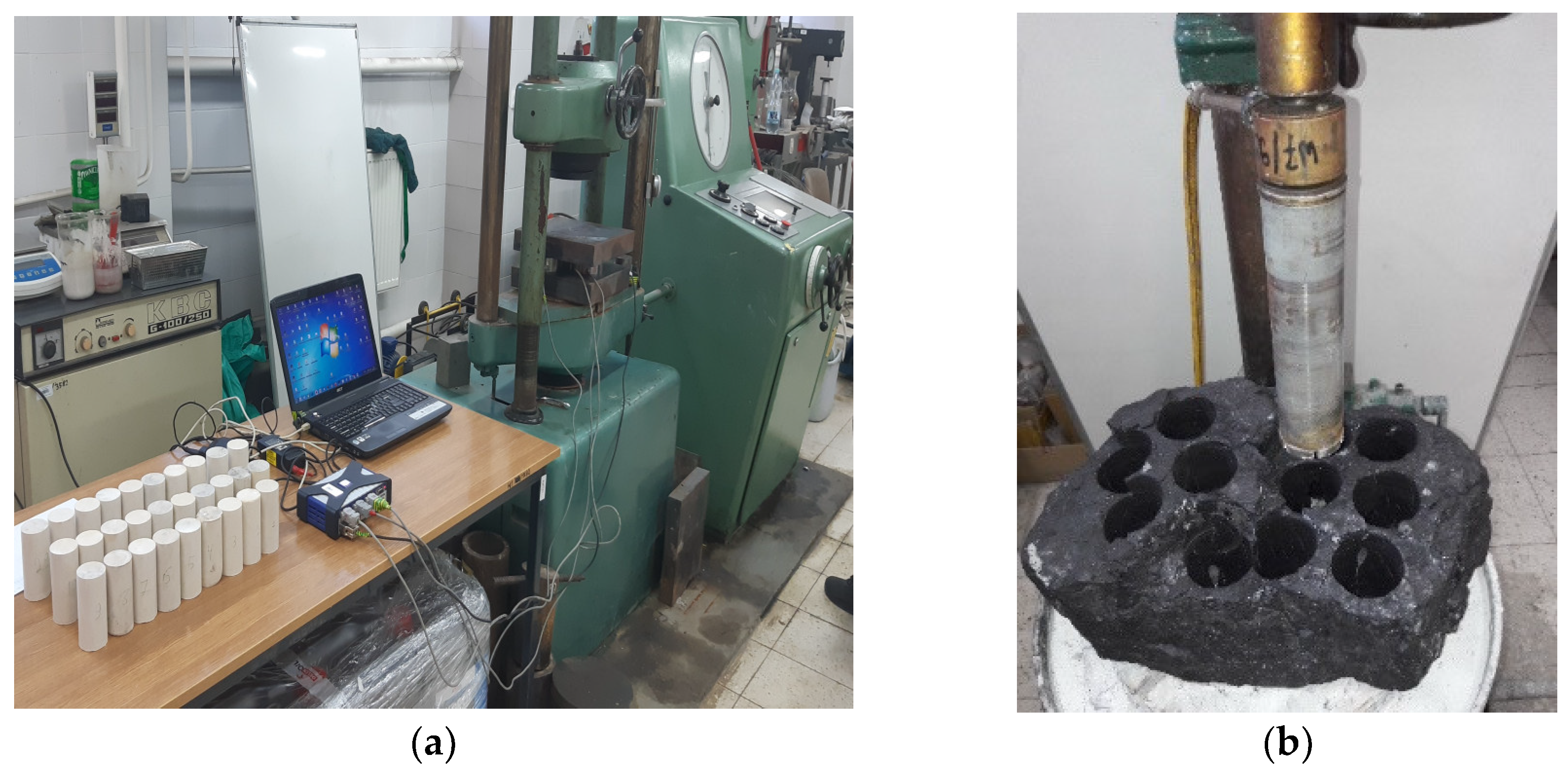
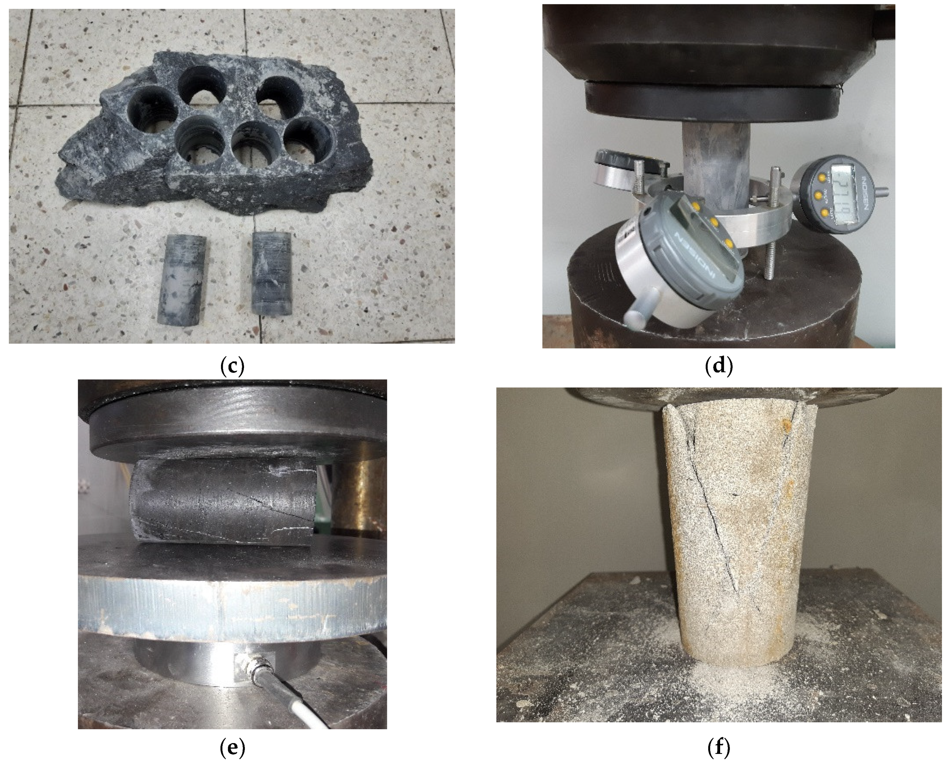
Laboratory Tests of Rocks from Driven Excavation
3. Choice of the Arch Yielding Support
3.1. Minimum Section Method
- xa—the width of the device (mm);
- xb—minimum movement distance between individual devices and the support (mm);
- ya—height of the device in a given cross-section (mm);
- yb—minimum movement distance between the device and the support (mm).
- —height of the cross-section of the excavation in the breakout (mm);
- —catalogue height of the ŁP8 support arches ;
- —width of the cross-section of the excavation in the breakout (mm);
- —catalogue width of the ŁP8 support arches
3.2. Ventilation Criterion
- Vrz—actual air flow velocity (m/s);
- Vmax—permissible maximum air velocity in the excavation (m/s);
- Vmin—the minimum permissible air velocity in the excavation (m/s).
- Qb—fan flow, m3/s (for Axial Flow Fan—Type ES 9-500/80, Qb = 10.2 m3/s) [37];
- Pq—the expenditure reserve ratio (dimensionless) is given by Equation (12):
- L—length of the duct, m (L = 80);
- k—leakage rate of the duct, m3/(sN1/2) (k = 0.003);
- r—unit resistance, flow rate of the duct, Ns2/m9 (r = 0.003590).
3.3. Arch Yielding Support Calculation
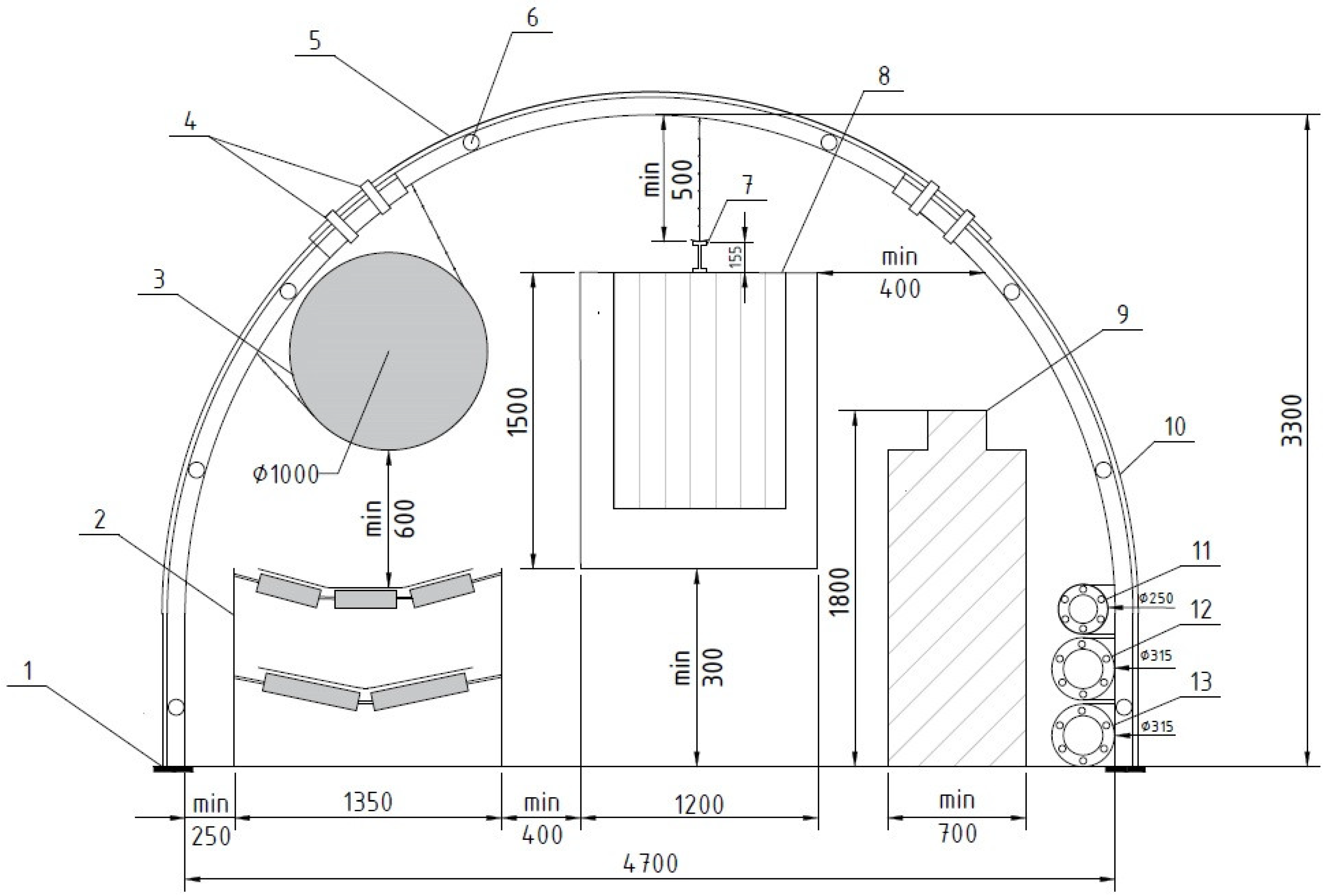
- Hc—height of the cross-section of roadway II in the breakout (m).
- d—arch yielding support spacing, m;
- —computational index of load capacity of support arches, MN/m;
- —computational load, MPa.
- WN—load capacity index of support arches, MN/m (for section V29 made of steel S480W, WN = 0.255) [39];
- kl—lining coefficient (in the designed excavation a tight lining will be used; therefore kl = 0.8; for mechanical, loose and non-loose lining, the coefficient is, respectively: 1.0, 0.6 and 0.4);
- 0.5544—constant value related to the factor of utilization of the maximum load capacity of arches;
- 0.8—constant value related to the load unevenness factor.
- kg—the rock mass weakening coefficient in the determined rock packet (Figure 7), which ranges from 0.79 to 3.64, kg = 1.881, was calculated according to Equation (18):
- —depth of roadway II, H = 800 m;
- rock quality designation, RQD = 40%;
- —coefficient of the influence of rock moisture on their strength, Rs = 0.75;
- ku—fault action coefficient for excavations that are located in the fault zone ku = 1.2;
- kα—coefficient of the influence of the transverse inclination of the rock layers, for α ≤ 15°; kα = 1.0, while for 15° ≤ α ≤ 35° kα = 1.15;
- kβ—coefficient of the longitudinal inclination of the excavation impact, for β ≤ 15° kα = 1.0, while for 15° ≤ β ≤ 25° kβ = 1.15 and for 25° ≤ β ≤ 35° kβ = 1.20;
- ke—exploitation edge influence factor (roadway II is outside the impact range and a distance of more than 120 m from the edge, therefore ke = 1);
- ks—the impact factor of the adjacent excavation (roadway II is driven parallel to roadway I at a distance of about 225 m) according to Formula (19), ks = 1.0:
- Wca—computational width, Wca = 7.1798, which is calculated according to Equation (21):
- Wc—width of the excavation in the breakout, Wc = 5 m (Figure 7);
- Hc—height of the excavation in the breakout, Hc = 3.6 m (Figure 7);
- k0—coefficient of the influence of the angle of internal friction of rocks in the sidewall (compressive strength of coal = 15.45 MPa (Table 1), k0 = 0.6055);
- qw—conditional pressure. Taking into account the effect of depth, coal compression strength and design width), qw = 0.0311 MPa, was calculated according to Equation (22):
- Wca—computational width, m;
- —depth of roadway II, H = 800 m;
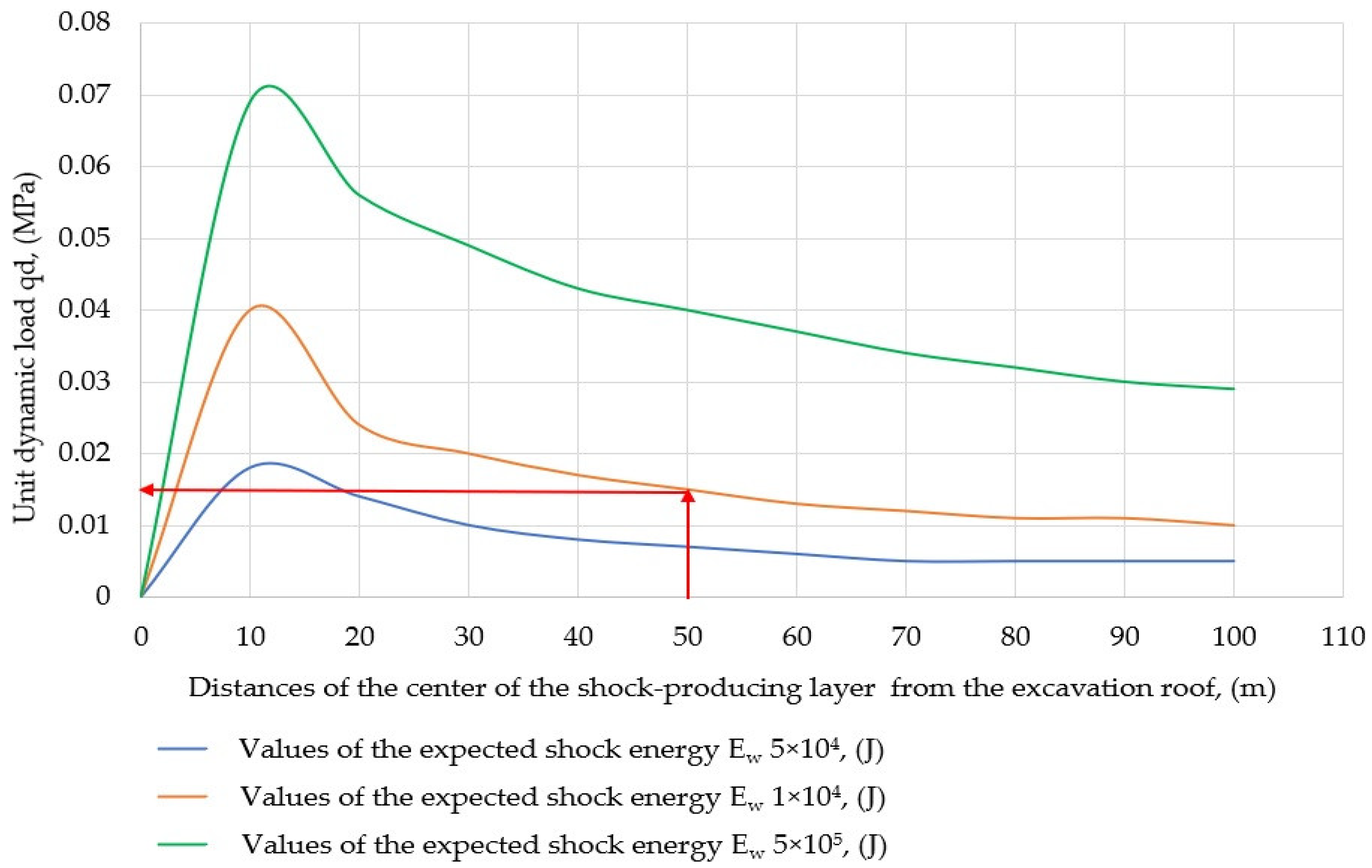
- Qd—dynamic unit load was determined on the basis of Figure 8, qd = 0.015 (roadway II is located 50 m below the shock layer, and the expected shock energy is 1 × 10⁵ J).
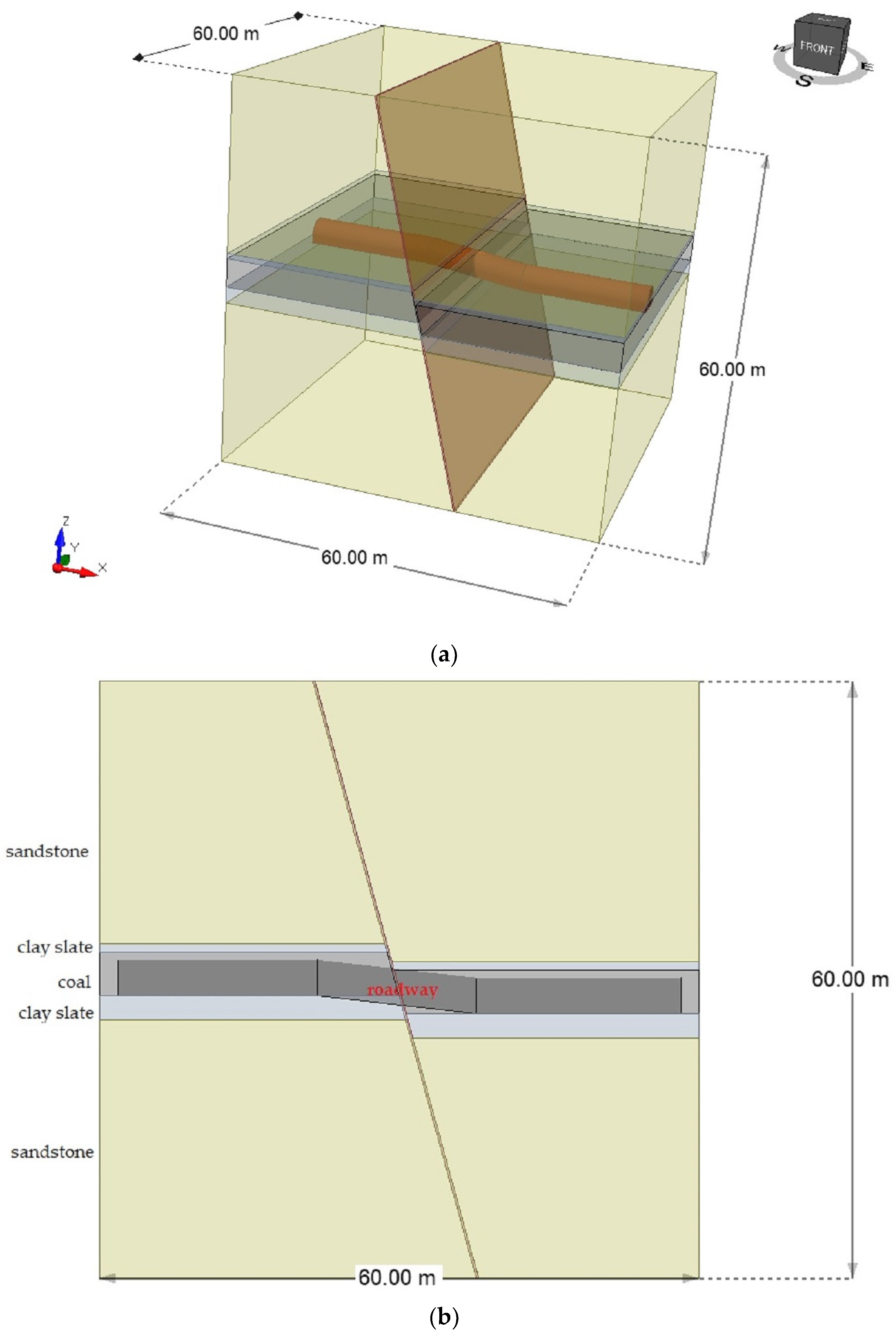
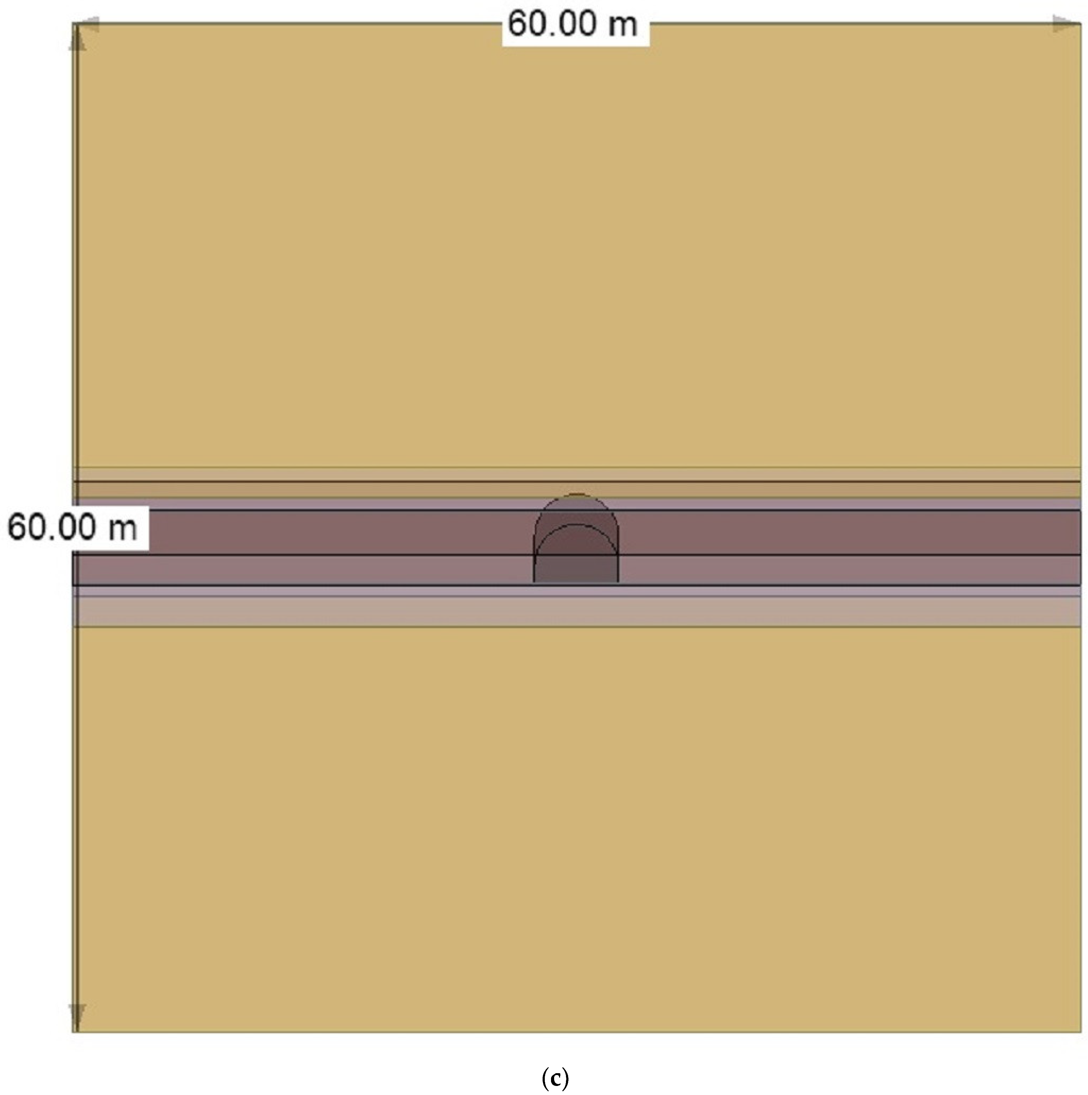
4. Discussion
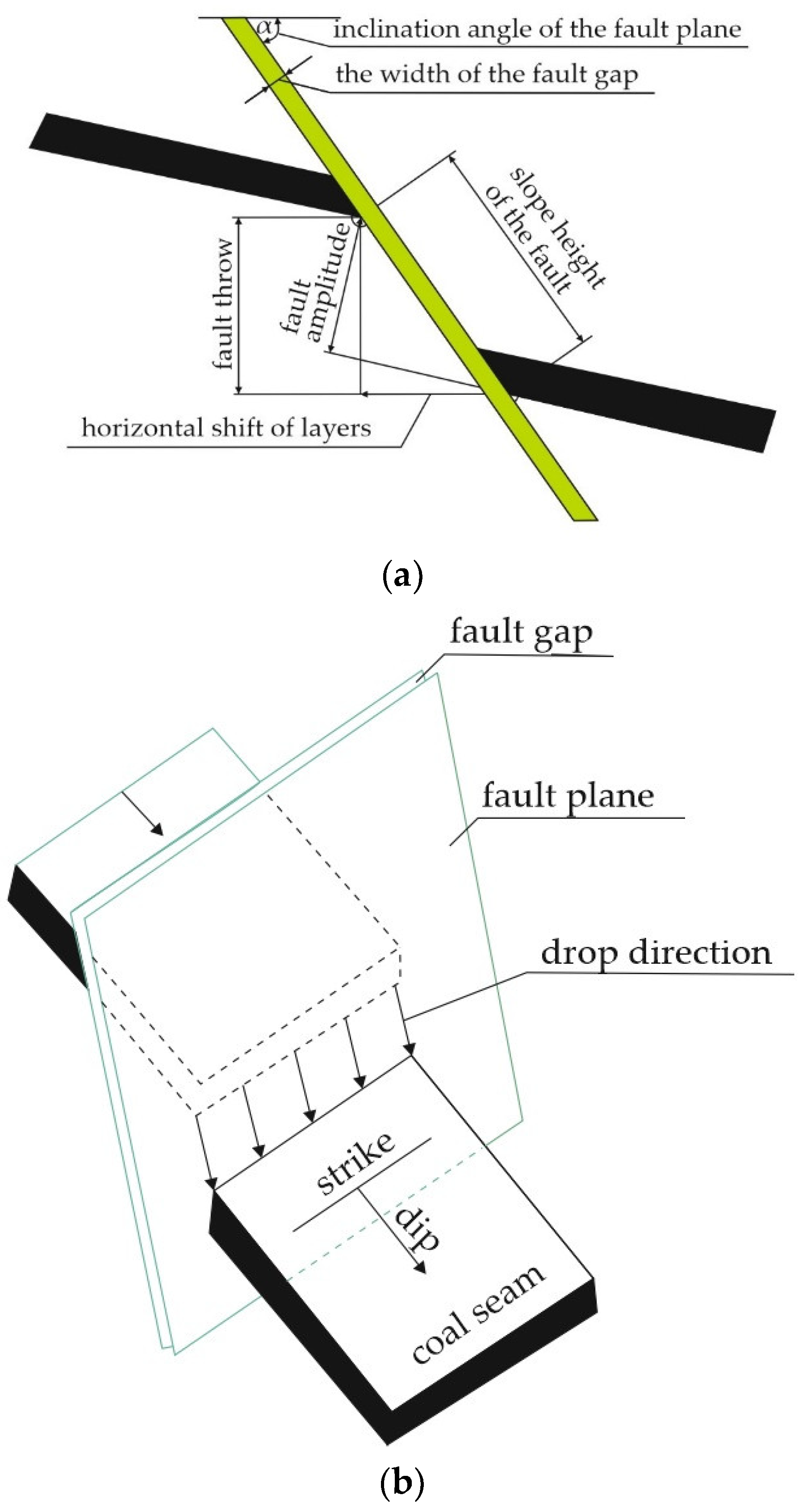
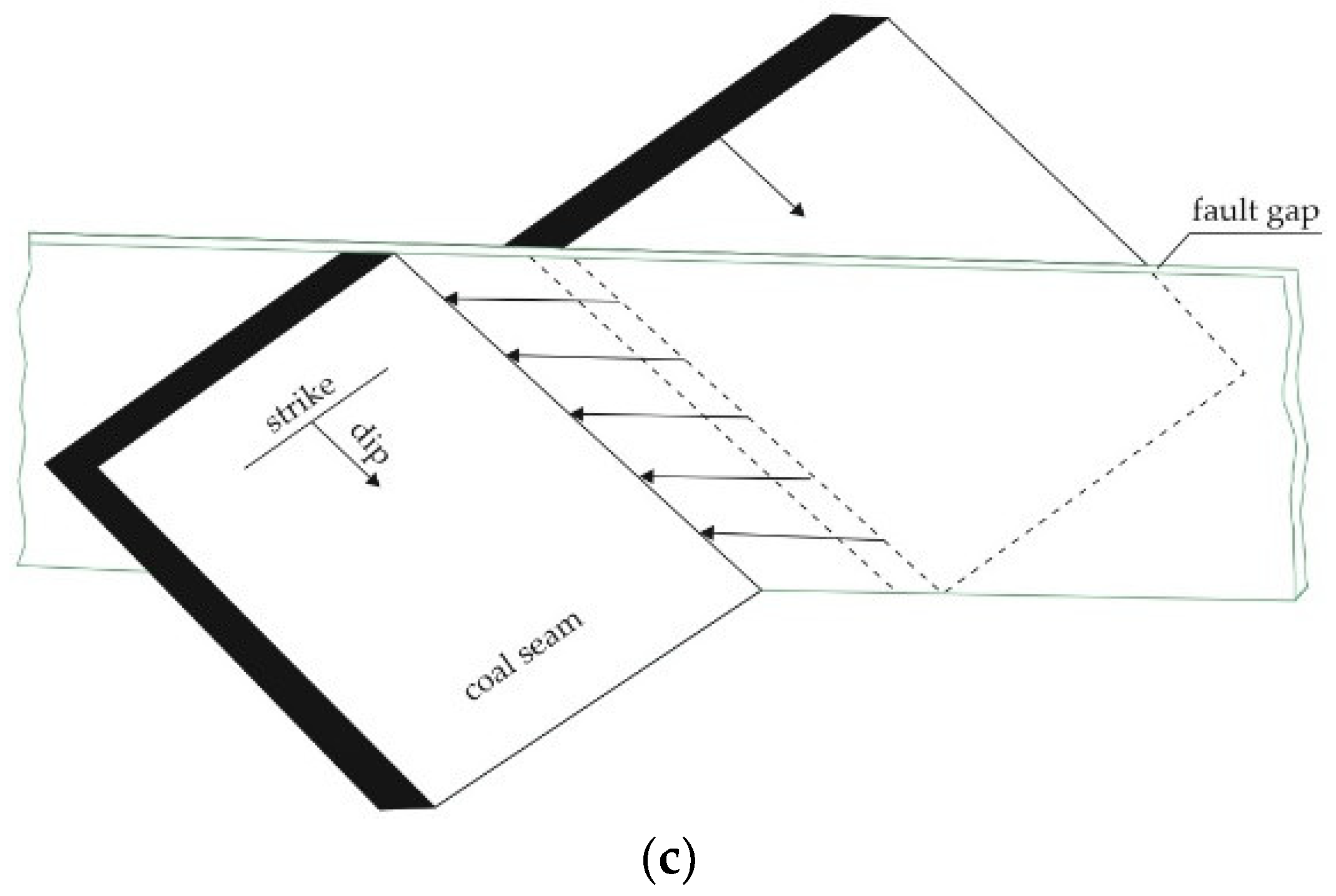
- fault action zone (m);
- the height of the fault throw (m);
- the angle of the fault plane ().
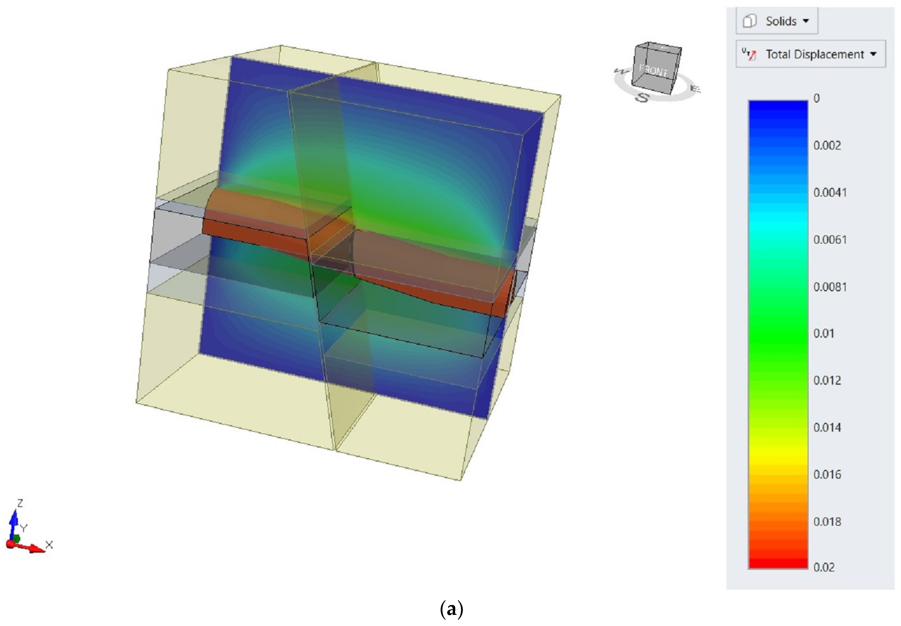
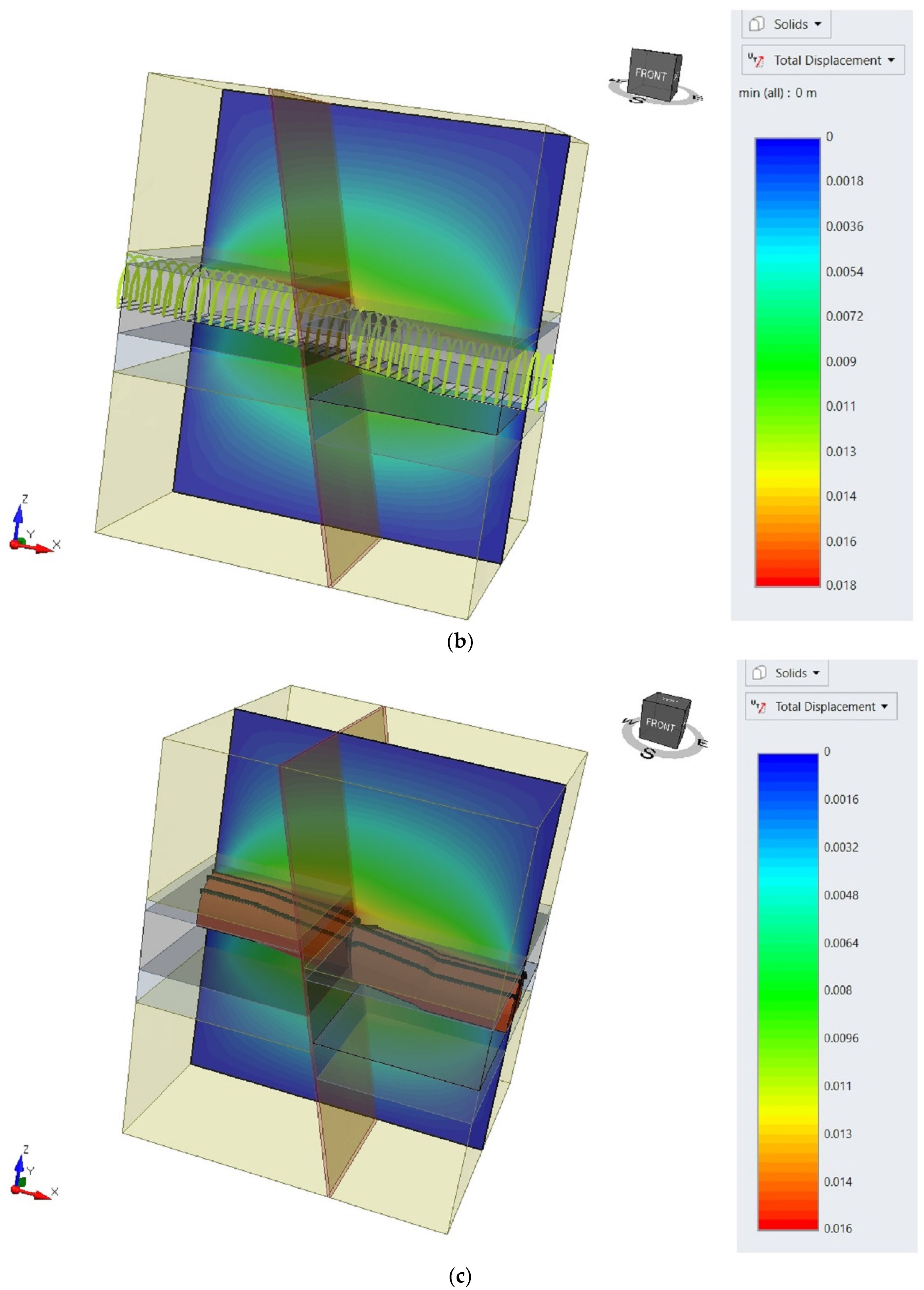
5. Conclusions
- The projected total displacement around the roadway without support, which crosses the fault, was 0.02 m, while the use of the arch yielding support at a distance of 0.9 m outside the fault and 0.75 m in the fault zone reduces the total displacement value by 10%;
- Additional reinforcement of the support in the form of steel straight segments contributes to a reduction in the value of total displacement by 11% and 20% compared to the excavation with and without the support.
Author Contributions
Funding
Institutional Review Board Statement
Informed Consent Statement
Data Availability Statement
Conflicts of Interest
References
- Cheng, G.; Li, L.; Zhu, W.; Yang, T.; Tang, C.; Zheng, Y.; Wang, Y. Microseismic investigation of mining-induced brittle fault activation in a Chinese coal mine. Int. J. Rock Mech. Min. Sci. 2019, 123, 104096. [Google Scholar] [CrossRef]
- Burtan, Z.; Zorychta, A.; Cieślik, J.; Chlebowski, D. Influence of mining operating conditions on fault behavior. Arch. Min. Sci. 2014, 59, 691–704. Available online: https://journals.pan.pl/Content/93633/PDF/10267-Volume59_Issue3-08_paper.pdf?handler=pdf (accessed on 20 November 2014). [CrossRef] [Green Version]
- Li, Q.; Li, J.; Zhang, J.; Wang, C.; Fang, K.; Liu, L.; Wang, W. Numerical Simulation Analysis of New Steel Sets Used for Roadway Support in Coal Mines. Metals 2019, 9, 606. [Google Scholar] [CrossRef] [Green Version]
- Xie, Z.; Zhang, N.; Wei, Q.; Wang, J.; Sharifzadeh, M. Study on Mechanical Properties and Application of a New Flexible Bolt. Appl. Sci. 2021, 11, 924. [Google Scholar] [CrossRef]
- Wang, P.; Zhang, N.; Kan, J.; Wang, B.; Xu, X. Stabilization of Rock Roadway under Obliquely Straddle Working Face. Energies 2021, 14, 5759. [Google Scholar] [CrossRef]
- Wang, J.; Apel, D.B.; Xu, H.; Wei, C.; Skrzypkowski, K. Evaluation of the Effects of Yielding Rockbolts on Controlling Self-Initiated Strainbursts: A Numerical Study. Energies 2022, 15, 2574. [Google Scholar] [CrossRef]
- Šňupárek, R.; Konečný, P. Stability of roadways in coalmines alias rock mechanics in practice. J. Rock Mech. Geotech. Eng. 2010, 2, 281–288. [Google Scholar] [CrossRef] [Green Version]
- Shan, R.; Li, Z.; Wang, C.; Wei, Y.; Bai, Y.; Zhao, Y.; Tong, X. Research on the mechanism of asymmetric deformation and stability control of near-fault roadway under the influence of mining. Eng. Fail. Anal. 2021, 127, 105492. [Google Scholar] [CrossRef]
- Mei, Y.; Li, W.; Yang, N.; Wang, G.; Li, T.; Sun, T. Failure Mechanism and Optimization of Arch-Bolt Composite Support for Underground Mining Tunnel. Adv. Civ. Eng. 2020, 2020, 5809385. [Google Scholar] [CrossRef] [Green Version]
- Kang, H.; Jiang, P.; Wu, Y.; Gao, F. A combined “ground support-rock modification-destressing” strategy for 1000-m deep roadways in extreme squeezing ground condition. Int. J. Rock Mech. Min. Sci. 2021, 142, 104746. [Google Scholar] [CrossRef]
- Liu, H.; Jiang, Z.; Chen, W.; Chen, F.; Ma, F.; Li, D.; Liu, Z.; Gao, H. A Simulation Experimental Study on the Advance Support Mechanism of a Roadway Used with the Longwall Coal Mining Method. Energies 2022, 15, 1366. [Google Scholar] [CrossRef]
- Horst, R.; Modrzik, M.; Ficek, P.; Rotkegel, M.; Pytlik, A. Corroded steel support friction joint load capacity studies as found in Piast-Ziemowit coal mine. Min. Inform. Autom. Electr. Eng. 2018, 1, 81–94. [Google Scholar] [CrossRef]
- Zhou, Q.; Herrera-Herbert, J.; Hidalgo, A. Predicting the Risk of Fault-Induced Water Inrush Using the Adaptive Neuro-Fuzzy Inference System. Minerals 2017, 7, 55. [Google Scholar] [CrossRef]
- Cao, Z.; Gu, Q.; Huang, Z.; Fu, J. Risk assessment of fault water inrush during deep mining. Int. J. Min. Sci. Technol. 2022, 32, 423–434. [Google Scholar] [CrossRef]
- Chen, J.; Dai, X.; Zhang, J. Analytical Study of the Confining Medium Diameter Impact on Load-Carrying Capacity of Rock Bolts. Math. Probl. Eng. 2021, 2021, 6680886. [Google Scholar] [CrossRef]
- Qian, D.; Zhang, N.; Pan, D.; Xie, Z.; Shimada, H.; Wang, Y.; Zhang, C.; Zhang, N. Stability of Deep Underground Openings through Large Fault Zones in Argillaceous Rock. Sustainability 2017, 9, 2153. [Google Scholar] [CrossRef] [Green Version]
- Kalmet. Available online: https://www.kalmet.com.pl/pl/oferta/elementy_obudow_gorniczych.html (accessed on 19 February 2022).
- Pytlik, A. Experimental studies of static and dynamic steel arch support load capacity and sliding joint temperature parameters during yielding. Arch. Min. Sci. 2020, 65, 469–491. [Google Scholar] [CrossRef]
- Grodzicki, M.; Rotkegel, M. The concept of modification and analysis of the strength of steel roadway supports for coal mines in the Soma Basin in Turkey. Studia Geotech. Mech. 2018, 40, 38–45. [Google Scholar] [CrossRef] [Green Version]
- Hutalab. Available online: http://www.hutalab.com.pl (accessed on 22 February 2022).
- Rotkegel, M. ŁPw Steel Arch Support–Designing and Test Results. J. Sustain. Min. 2013, 12, 34–40. [Google Scholar] [CrossRef] [Green Version]
- Li, W.; Liu, J.; Chen, L.; Zhong, Z.; Liu, Y. Roadway Support in Deep “Three-Soft” Coal Seam: A Case Study in Yili Mining Area, China. Shock Vib. 2021, 2021, 8851057. [Google Scholar] [CrossRef]
- Yang, R.; Li, Q.; Li, Q.; Zhu, X. Assessment of Bearing Capacity and Stiffness in New Steel Sets Used for Roadway Support in Coal Mines. Energies 2017, 10, 1581. [Google Scholar] [CrossRef] [Green Version]
- Lv, Z.; Qin, Q.; Jiang, B.; Luan, Y.; Yu, H. Comparative study on the mechanical mechanism of confined concrete supporting arches in underground engineering. PLoS ONE 2018, 13, e0191935. [Google Scholar] [CrossRef] [PubMed] [Green Version]
- Wu, H.; Jia, Q.; Wang, W.; Zhang, N.; Zhao, Y. Experimental Test on Nonuniform Deformation in the Tilted Strata of a Deep Coal Mine. Sustainability 2021, 13, 13280. [Google Scholar] [CrossRef]
- Wang, H.; Jiang, Y.; Xue, S.; Mao, L.; Lin, Z.; Deng, D.; Zhang, D. Influence of fault slip on mining-induced pressure and optimization of roadway support design in fault-influenced zone. J. Rock Mech. Geotech. Eng. 2016, 8, 660–671. [Google Scholar] [CrossRef] [Green Version]
- Wang, H.; Shi, R.; Lu, C.; Jiang, Y.; Deng, D.; Zhang, D. Investigation of sudden faults instability induced by coal mining. Saf. Sci. 2019, 115, 256–264. [Google Scholar] [CrossRef]
- Lu, Y.; Wei, W.; Zhiyu, T. Study on Mechanical Mechanism and Stability of Surrounding Rock in Fault Structure Roadway. ResearchSquare 2021, 2, 1–22. [Google Scholar] [CrossRef]
- Adoko, A.C.; Yakubov, K.; Kaunda, R. Reliability Analysis of Rock Supports in Underground Mine Drifts: A Case Study. Geotech. Geol. Eng. 2021, 11, 2101–2116. [Google Scholar] [CrossRef]
- Xiong, Y.; Kong, D.; Cheng, Z.; Wen, Z.; Ma, Z.; Wu, G.; Liu, Y. Instability Control of Roadway Surrounding Rock in Close-Distance Coal Seam Groups under Repeated Mining. Energies 2021, 14, 5193. [Google Scholar] [CrossRef]
- Regulation of the Minister of the Environment of January 29, 2013 on Natural Hazards in Mining Plants. Natural Hazards in Mining Plants. Available online: https://www.prawo.pl/akty/dz-u-2021-1617-t-j,17955795.html (accessed on 10 February 2022). (In Polish).
- Polish Standard: PN-93/G-04558. Hard Coal. Determination of Spontaneous Ignition Indexes. Polish Committee for Standardization: Warszawa, Poland, 1993. (In Polish)
- Polish Standard: PN-G/06009. Horizontal and Inclined Underground Roadways in Mine Enterprises–Movement Clearances and Dimensions of Man Passages. Polish Committee for Standardization: Warszawa, Poland, 1997. (In Polish)
- Polish Standard: PN-93/G-15000/02. Roadway Support with Susceptible Timber Frames Made of Special Sections. Arch Susceptible Frames ŁP of Sections Type V, Series A. Dimensions. Polish Committee for Standardization: Warszawa, Poland, 1993. (In Polish)
- Tchórzewski, K. Regulation of the Minister of Energy on detailed requirements for the operation of underground mining plants of 23 November 2016. J. Laws 2017, 1118, 18. (In Polish) [Google Scholar]
- Wacławik, J. Mine Ventilation; AGH Publishing House: Kraków, Poland, 2010; Volume I, p. 391. (In Polish) [Google Scholar]
- CST. Available online: https://cst-germany.com/pl/product/axial-flow-fan-type-es9-500-80-pu-stage-id184 (accessed on 24 February 2022).
- Rułka, K.; Mateja, J.; Kowalski, E.; Skrzyński, K.; Stałęga, S.; Wojtusiak, A.; Schinohl, J. Simplified Rules for the Selection of Frame Support for Roadway Workings in Hard Coal Mining Plants; Central Mining Institute Publishing House: Katowice, Poland, 2001; pp. 1–30. (In Polish) [Google Scholar]
- Polish Standard: PN-H-93441-1:2013-12. Hot Rolled Steel Sections for Mining-Part 1: General Requirements and Research. Polish Committee for Standardization: Warszawa, Poland, 2013. (In Polish)
- RocScience. Available online: https://www.rocscience.com/software/rs3 (accessed on 10 March 2022).
- RocData. Available online: https://www.rocscience.com/support/rocdata/release-notes (accessed on 12 March 2022).


| Type of Rock | Density (kg/m3) | Compressive Strength (MPa) | Tensile Strength (MPa) | Young’s Modulus (GPa) |
|---|---|---|---|---|
| Coal | 1296 | 15.45 | 1.37 | 2.3 |
| Claystone | 2440 | 16.5 | 1.55 | 10.3 |
| Sandstone | 2560 | 47 | 3.62 | 5.4 |
| Type of Machine or Device | Width (mm) | Height (mm) |
|---|---|---|
| Suspended monorail: BIZON 120-X | 1200 | 1500 |
| Belt conveyor: GWAREK-1000 | 1350 | 1000 |
| Fire pipeline | 315 | |
| Drainage pipeline | 315 | |
| Compressed air pipeline | 250 | |
| Duct diameter | 1000 | |
| Passage for miners | 700 | 1800 |
| Rail of suspended monorail | 155 | |
| Movement intervals | ||
| From | To | Minimum distance (mm) |
| Belt conveyor | Arch yielding support | 250 |
| Suspended monorail | Belt conveyor | 400 |
| Duct | Belt conveyor | 600 |
| Floor | Suspended monorail | 300 |
| Rail of suspended monorail | Roof arch | 500 |
| Type of Support | Height, Hcatalogue (mm) | Width, Scatalogue (mm) | Cross-Section (m2) |
|---|---|---|---|
| ŁP7/V29/A | 3100 | 4200 | 11.08 |
| ŁP8/V29/A | 3300 | 4700 | 13.07 |
| ŁP9/V29/A | 3500 | 5000 | 14.76 |
| Cost | Arch Yielding Support with a Cross-Section of 13 m2 | Rock Bolt Support in Length 2.5 m |
|---|---|---|
| Labour, % | 19.51 | 37.78 |
| Material, % | 71.81 | 51.11 |
| Equipment, % | 3.25 | 6.67 |
| Transport, % | 5.42 | 4.44 |
| Total cost of 1 m, PLN | 3690 | 2250 |
| Type of Rock | Unit Weight (MN/m3) | Compressive Strength (MPa) | Young’s Modulus (MPa) | Poisson Ratio | Geological Strength Index | mb | s | a |
|---|---|---|---|---|---|---|---|---|
| Coal | 0.0127 | 15.45 | 2300 | 0.3 | 65 | 0.756 | 0.009 | 0.502 |
| Claystone | 0.0239 | 16.5 | 10,300 | 0.23 | 70 | 1.678 | 0.018 | 0.501 |
| Sandstone | 0.0251 | 47 | 5400 | 0.25 | 75 | 5.169 | 0.036 | 0.501 |
| Fault | 0.0127 | 12.36 | 2000 | 0.3 | 50 | 0.185 | 0.001 | 0.506 |
Publisher’s Note: MDPI stays neutral with regard to jurisdictional claims in published maps and institutional affiliations. |
© 2022 by the authors. Licensee MDPI, Basel, Switzerland. This article is an open access article distributed under the terms and conditions of the Creative Commons Attribution (CC BY) license (https://creativecommons.org/licenses/by/4.0/).
Share and Cite
Skrzypkowski, K.; Zagórski, K.; Zagórska, A.; Apel, D.B.; Wang, J.; Xu, H.; Guo, L. Choice of the Arch Yielding Support for the Preparatory Roadway Located near the Fault. Energies 2022, 15, 3774. https://0-doi-org.brum.beds.ac.uk/10.3390/en15103774
Skrzypkowski K, Zagórski K, Zagórska A, Apel DB, Wang J, Xu H, Guo L. Choice of the Arch Yielding Support for the Preparatory Roadway Located near the Fault. Energies. 2022; 15(10):3774. https://0-doi-org.brum.beds.ac.uk/10.3390/en15103774
Chicago/Turabian StyleSkrzypkowski, Krzysztof, Krzysztof Zagórski, Anna Zagórska, Derek B. Apel, Jun Wang, Huawei Xu, and Lijie Guo. 2022. "Choice of the Arch Yielding Support for the Preparatory Roadway Located near the Fault" Energies 15, no. 10: 3774. https://0-doi-org.brum.beds.ac.uk/10.3390/en15103774