Article

Improved Operation Strategy for the High Voltage Input Stage of a Multi-Port Smart Transformer

by
Enrique Romero-Cadaval
*,
Fermín Barrero-González
,
Eva González-Romera
,
María-Isabel Milanés-Montero
and
Carlos Roncero-Clemente
Power Electrical and Electronic Systems R+D Group, Department of Electrical, Electronic and Control, School of Industrial Engineering, University of Extremadura, 06006 Badajoz, Spain
*
Author to whom correspondence should be addressed.
Submission received: 21 March 2022 / Revised: 12 May 2022 / Accepted: 19 May 2022 / Published: 20 May 2022
(This article belongs to the Special Issue Advances in Multilevel Converter/Inverter Topologies and Applications)

Abstract

:
Smart transformers are considered a crucial part of future smart grids as they will operate as the energy router and be able to control the power flows from and to the microgrids since they are placed in the border. A multi-port transformer can integrate different energy resources, loads and energy storage systems, optimizing the power flows between these elements. Combining both concepts, a multi-port smart transformer is obtained that is able to integrate efficiently distributed and renewable energy resources, electric vehicle chargers, prosumers and energy storage in both AC and DC microgrids. Nevertheless, the operation of these transformers, composed of several modules connected in series to the high-voltage grid is not easy, mainly due to the different power consumed or generated by each module. In this paper this issue is analyzed and different operation strategies for coordinating the series-connected modules at the input side are studied by simulation. The paper will expose how it is possible to extend the proper operation of the system if a reactive power controller is implemented.

1. Introduction

Electric Energy Systems (EES) are evolving into more complex systems, where operation strategies are planned in shorter interval periods day by day. Traditional unidirectional EES, where the energy comes from central generation plants to the final end-users by transmission and distribution grids, are moving to smart grids, where the EES are divided and controlled in the so-called microgrids (MGs). Their strategies aim to operate as a self-sufficient energy network minimizing the energy interchanges with other MGs.
In this context, the conventional energy transformer can be considered the optimal point to control the power flows between the MG and the grid of microgrids, and can be considered as an energy router and named as a smart transformer (ST) [1,2], presenting the conventional topology shown in Figure 1a. Each of the modules that compose the ST are mainly based in dual active full-bridge (DAB) topologies and a high-frequency transformer [2,3,4]. There are many works that deal with the advantages of solid state transformers (SST) compared with other alternatives. A comparison of different alternatives is made in [4] and is summarized in Table 1.
To control the input side of the series-connected modules, different modulation strategies can be used, very similar to the ones used in Multi-Modular Converters (MMCs) [3,4,5,6,7,8,9,10,11], highlighting as the most used, modulation based on phase displacement [8,9].
An analysis of different modulation strategies used in an MMC has been conducted in [5,6,7,8,9,10,11,12,13,14]. These works try to optimize the operation of the MMC by mitigating the imbalance in voltage capacitors, reducing the circulation currents or reducing the common-mode voltage.
STs, as the core of the smart grid of microgrids (SGM), not only control the power flows to or from the SGM, but are also a key element that can control the energy generated by renewable resources as well as the energy to be charged or discharged in energy storage systems (ESS). To give the ST the ability to integrate the energy from different components (sources and sinks), the concept of a multi-port ST (MPST) [11,12,13,14,15] can be exploited, with different terminals able to integrate DC and AC microgrids, loads or ESS (Figure 1b, Figure 2 and Figure 3), and to implement strategies to optimally manage, in a coordinated way, all these resources.
Figure 1b [15,16,17] shows the potential architecture of an MPST as an example. In this case the system is composed of four ports: it has a single high-voltage (HV) port to connect with the SGM and several low-voltage (LV) ports, one in AC to connect to a single MG, another in DC to control the energy generated by a photovoltaic plant (PVP) and the last one in DC to integrate an ESS. The architecture is based on electrical transformers, to guarantee the usually required galvanic isolation, that are operated at high frequencies by using power electronic converters (PECs) to minimize the size and weight.
Modulation strategies for the proposed MPST are not in the scope of this work (as they have been analyzed in previous works [15]), but it should be highlighted that in this work, the different modules that compose the input side of the MPST do not have to be balanced, but, conversely, the modules operate in an unbalanced strategy as each of them supply a different power to the device or resource connected at their input port.
To connect the PECs (usually operating at LV) to the HV side of the ST, they are associated in series, requiring so many converters due to the need to divide the grid HV to the operation LV of the PEC. This concept is used a great deal in MMCs. Usually, converters in the MMCs operated at the same power point (as they are connected in series, the current circulating through the converters is the same and this implies that, ideally, input operation voltages are the same in all converters). It should be highlighted that the operation strategy for the MPST in this work is not the same as that in conventional MMCs, as not all the converters operate at the same power because it depends, as commented, on the power generated or consumed by the different ports the converter is associated with.
The MPST concept has been presented and analyzed in several previous works. In [18] an MPST is analyzed that has different ports for integrating DC microgrids, PV arrays, DC loads and DC electric vehicle chargers (Figure 2a). In this case, all the converters have output modules that share the same LV DC bus, and the input MMC modules, connected to the AC grid and MVDC bus, do not operate at different power points as in the case analyzed in this work.
In [19] a different alternative is proposed for an MPST, integrating into the grid different renewables energies (PV and wind generators) and ESS (Figure 2b). In this case, all the converters share the same transformer core and have a single inverter connected to the grid, meaning it is unnecessary to control the input power between the different converters at the input side as in the case proposed in this work.
Recently, in [20], a solid state transformer and hybrid transformer with integrated energy storage in active distribution grids was presented (Figure 3). In [20] attention was not paid to the modular architecture, but instead the focus was on the possibility of the input side being composed by several series-connected modules that could operate at different powers.
One of the novelties of this work is the analysis of the input side of the MPST when it has a modular architecture with several modules connected in series to the HV grid. Each of the input modules are associated to different output ports in the MPST and they can operate in an unbalanced way at different working powers.
The main contribution of this work is the analysis of operation strategies for the proposed modular architecture for the MPST (Figure 1b), where the different input PECs are connected in series to the HV grid and operate with different amplitude modulation indexes. If the difference between the working powers of the converters is high enough, the converters working with the higher power can enter into the PWM overmodulation zone, causing the MPST to become out of control.
There are several works that have dealt with this problem previously, see [21,22,23,24,25]. There are two main actions to extend the lineal operation range: the first is to improve the modulation strategy to extend the lineal operation beyond 1 [23], the second group of actions use the reactive power control to prevent the operation in the overmodulation zone. In [21] it is demonstrated how by controlling the reactive power it is possible to operate several output modules at different powers and to allow their operation at different DC output voltages.
Reference [22] validated how is it is possible to control the cascaded active rectifier stage of an SST, implementing a voltage feedback-based controller for the output-parallel DAB converter stage and a single-phase-based three-phase PR controller for a three-phase inverter. As a result the proposed control is able to realize voltage and power balance, even in the case of mismatched parameters between modules.
Reference [23] proposed to route the power in a CHB converter based on the condition of the components in connected power paths. The loading of the converter cells was controlled to alter the power processed in the different paths, and multifrequency power routing using the third harmonic was proposed to improve the unbalanced power sharing between the cells. This work introduces the concept of maximum unbalanced power loading and does not consider the reactive power control as this assumes a unity power factor operation.
In [24] a power adaptive control strategy was proposed to make a single-phase CHB PV grid-tied inverter operate normally under severe power imbalance conditions. This method divided the system into three operating modes based on modulation waveforms being calculated by different methods. As a result the proposed power adaptive control strategy could further expand the operation range of a single-phase CHB PV inverter and obtain as much PV energy as possible under the premise of normal operation.
Finally, in [25] a reactive power controller for the power imbalance of a cascaded photovoltaic converter is discussed. Based on the detailed mathematic analysis, the proposed scheme reasonably distributes the reactive power into every power module, improving not only the adaptability of the cascaded photovoltaic converter but also reducing the required reactive power.
This work is focused on the second group of solutions that look to extend the operation range by controlling the reactive power. The modulation strategy is not the focus, and a conventional unipolar PWM sinusoidal strategy is considered. The main aims of this work are: to obtain an average model that allows users to simulate the operation over the long term; to validate the operation of the MPST in future works when integrated in the smart grids and running energy management algorithms; to analyze different reactive control strategies to extend the operation of the MPST and prevent overmodulation, which can be used in future works when unbalanced operation of the different ports is critical, it being possible that some of them operate with positive power (they consume power, loads), others with negative power (they are producing, such as photovoltaic modules) and others could have either positive or negative power (they are energy storage systems that can be charged or discharged).
The rest of the paper is organized as follows. In Section 2, the studied architecture is presented and the general ideal operation of an MPST is proposed. The improved strategy for extending operation is presented and discussed in Section 3 and validated by simulation in Section 4, considering different scenarios. Finally, conclusions are given in Section 5.

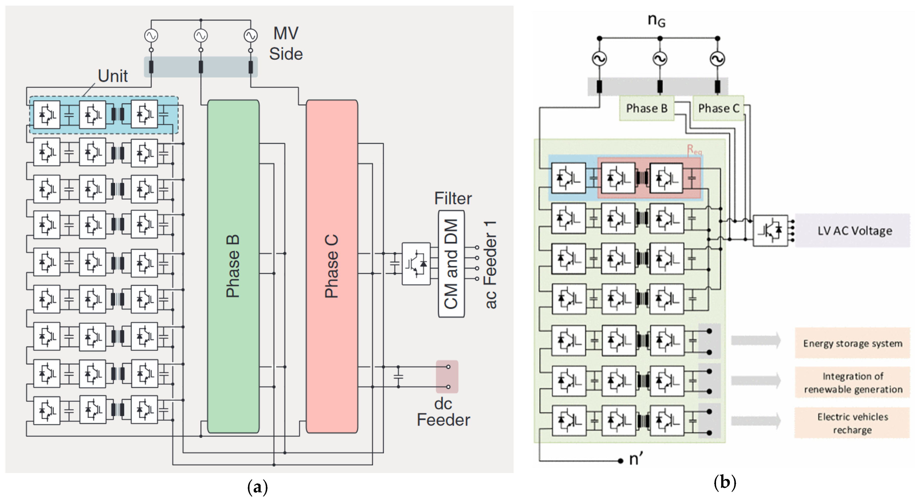
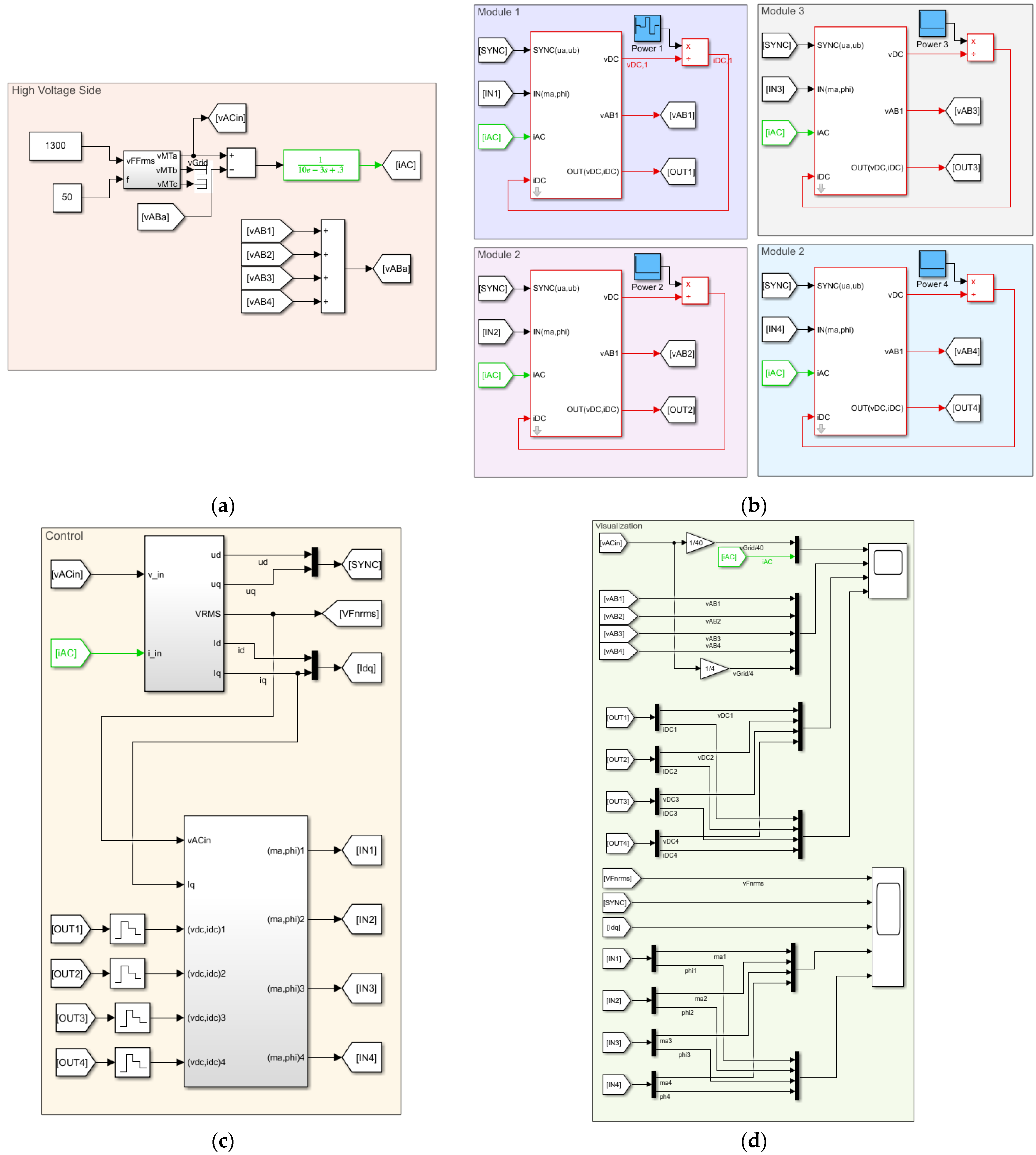
2. Designing and Modelling the Multi-Port Smart Transformer

The architecture of the MPST schematically shown in Figure 1b is considered in this paper as the reference for a detailed analysis. The MPST is composed by several basic, modular, and identical power electronic blocks (PEB) with a nominal power PPEB. PEB could have different topologies [3] and the full-bridge alternative is selected in this paper because it allows better harmonic control (as discussed in [10,16,17]). The analysis of the proposed MPST can be conducted for a single-phase and easily extended to the three-phase operation, as the topology shown in Figure 1b is star connected.

2.1. Basic Design

Let us first consider an MPST that has one HV port and several LV ports. The number of modules to be connected in series, nS, to conform with the input port connected in series with the HV grid, is determined according to Equation (1)
n S V H V V P E B ,
where VHV is the nominal phase-to-neutral voltage of the grid and VPEB is the nominal PEB input voltage.
We also have to consider that to reach the desired output power port Pj at a given output port j, the output of several PEBs has to be connected in parallel. If PPEB is the nominal power of a single PEB, the required number of PEBs to be output-parallel-connected, nPj, is given by
n P j P j P P E B .  
To guarantee that the MPST can be built fulfilling the input and output requirements, a nominal power should be selected for each PEB, PPEB, that gives
n S n P j P P E B V P E B V H V P j .
The final number of PEBs, nPEB, is selected to be the maximum of the number of series blocks given by Equations (1) and (3):
n P E B max ( V H V V P E B , P j P P E B ) ,
this being determined by voltage or power requirements depending on the application (VHV, Pj) and on the PEB (VPEB, PPEB).

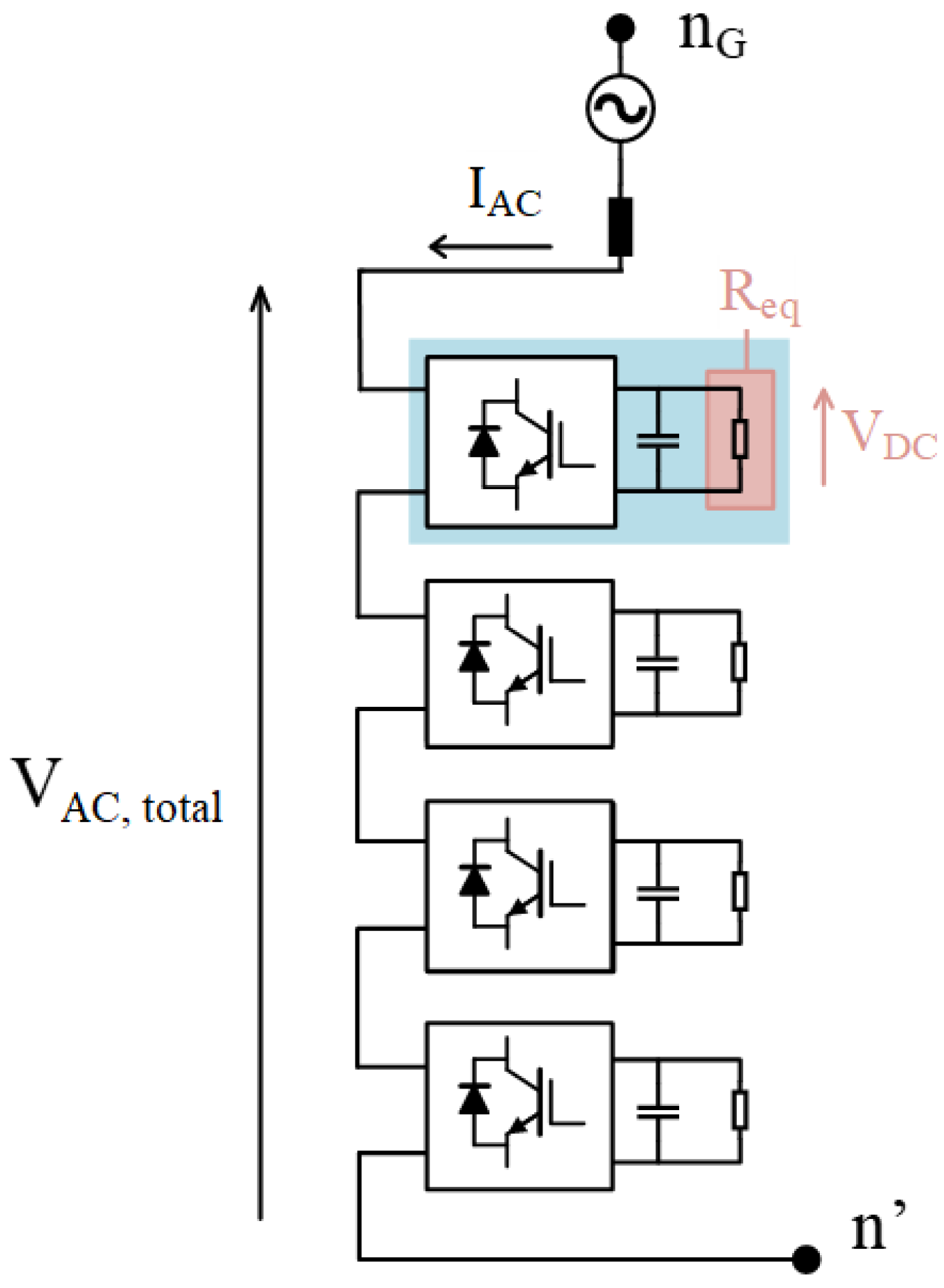
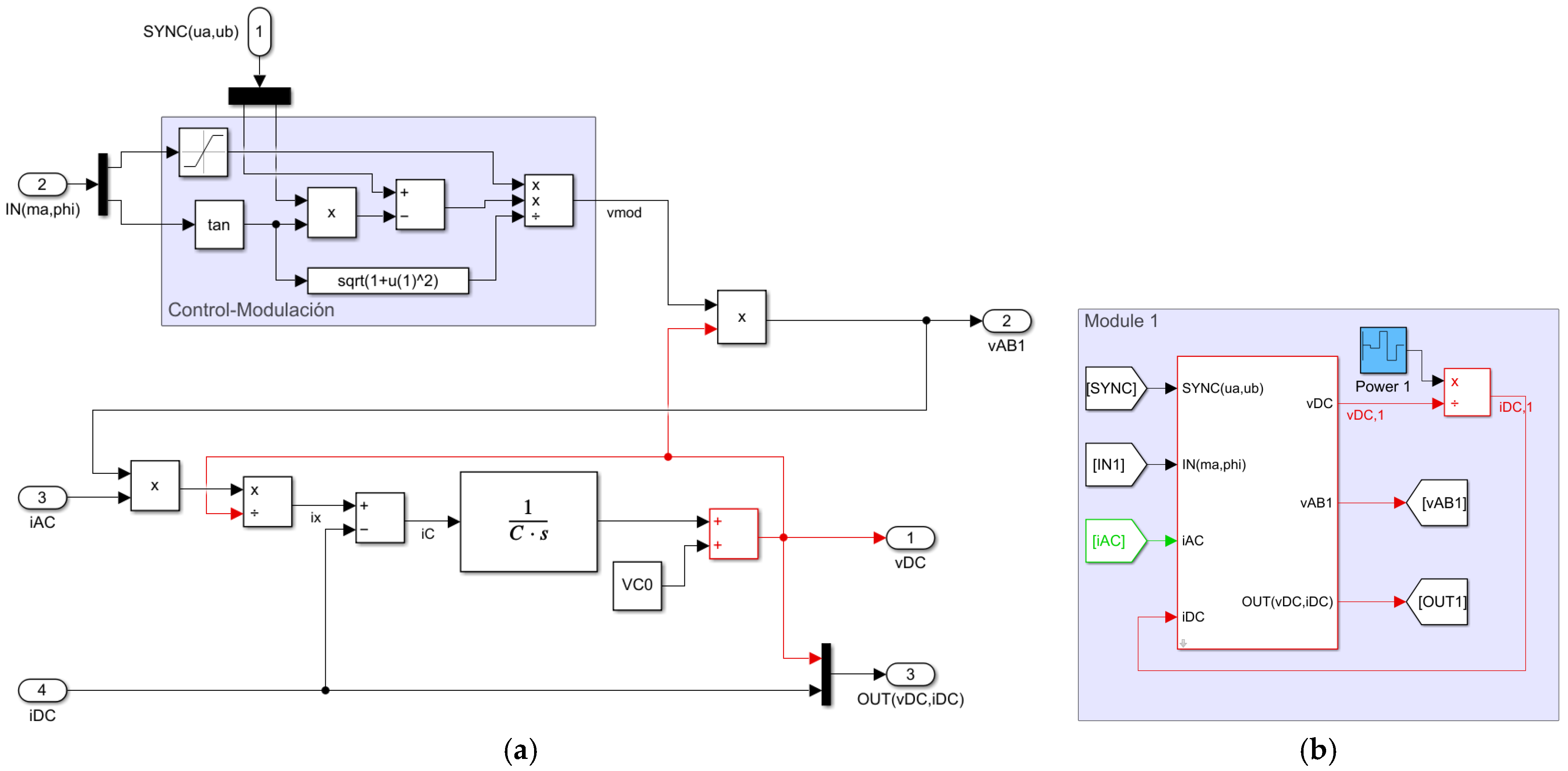
2.2. PEB Model Used for Analysis of Input Port in Series Connection

This paper is focused on the analysis of the input port of the MPST that is connected to the HV grid and composed by the series connection of the input terminal of several PEBs (nPEB), as designed in the previous section.
At this point, only the input converter of the PEB is considered, substituting all the devices connected to the output capacitor of the first stage, as an equivalent resistance (Figure 1b) that can consume the output power of the given port (Pi), as depicted in Figure 4.
If a given port j is composed of only a single PEB, neglecting losses and assuming a converter efficiency of 100%, the averaged model shown in Figure 5 can be obtained, where the voltage at the input terminals of the PEB, vPEBij(t), (vAB1 in the scheme of Figure 5) is determined by multiplying the modulation waveform by the output capacitor voltage, vDCj.
Modulation waveforms are built from two sinusoidal synchronized waveforms [17], one in phase with the grid voltage, ua, and the other in quadrature, ub, to provide a given amplitude modulation index, ma, and a phase displacement, phi (or δ).
The output capacitor voltage, vDCj, (vDC in Figure 5) can be estimated from its current, iCj, as determined by the next equations
i C j ( t ) = p i j ( t ) v D C j ( t ) i P E B o , j ( t ) = v P E B i j ( t ) i H V ( t ) v D C j ( t ) i P E B o , j ( t ) v D C j   ( t ) = V C 0 + 0 t i C j ( t )   d t ,
where pij(t) is the instantaneous input power, iHV(t) is the HV grid AC current that circulates through the input terminals of all PEBs connected in series (iAC in Figure 5), iPEBo,j(t) is the PEB output DC current (iDC in Figure 5) that flows by the equivalent resistance Rj (Req in Figure 4) and VC0 is the capacitor initial voltage at t = 0 established by the pre-charging system.
The final masked averaged model is shown in Figure 5b, where it can be seen that there are four main inputs: synchronization signals, modulation signals, the HV grid AC current and PEB output DC current; and two outputs: the PEB output DC voltage and PEB input AC voltage. The third input is only for visualization purposes.
It can also be highlighted that it is assumed that the output ports deliver a given power poj(t) and the PEB output current is determined by using
i P E B o , j ( t ) = p o j ( t ) v D C j ( t ) .
The obtained model is still valid when an output port j of the MPST with nominal power Pj is composed of nPj PEBs connected in parallel. In this case, a balanced situation operation is assumed when all the PEBs that compose the port have the same voltage at the input terminals ( V P E B i j , k ) and the same current at the output terminals ( I P E B o j , k )
V P E B i , j , k = V P E B i , j , 1 ;   I P E B o , j , k = I P E B o , j , 1 ;   k [ 2 , n P i ]
and an equivalent PEB (EPEB) can be used with the next parameters
P i j = P o j = n P j P P E B i j = n P j P P E B o j V E P E B i j = n P j V P E B i j , 1 I E P E B i j = I P E B i j , 1 V E P E B o j = V P E B o j I E P E B o j = n P j I P E B o j C E P E B = n P j C P E B .

3. Control Operation of HV Terminals

In this section, different alternatives to control the input side of the PEB will be introduced. It should be highlighted that the main problem to be solved is how to share the total input voltage VAn determined as
V A n = V P E B i j ,  
when they are operating at a different output power (Pj) but with the same input current as their input terminals are series-connected
I P E B i j = I H V .
This can be mainly carried out by controlling the modulation waveforms as the output power, generally, determined by
P j = V P E B i j I H V cos ( δ j φ ) = m a j V D C j 2 I H V cos ( δ j φ ) ,
where maj is the amplitude modulation index and δj is the phase displacements of the modulation waveforms for PEB j, and ϕ is the phase of the grid current, assuming that the reference for phases is the grid voltage (as defined in Figure 6).
In this work, it is considered that all PEBs operate with the same phase for the modulation waveforms, letting
δ j = δ ;   j .

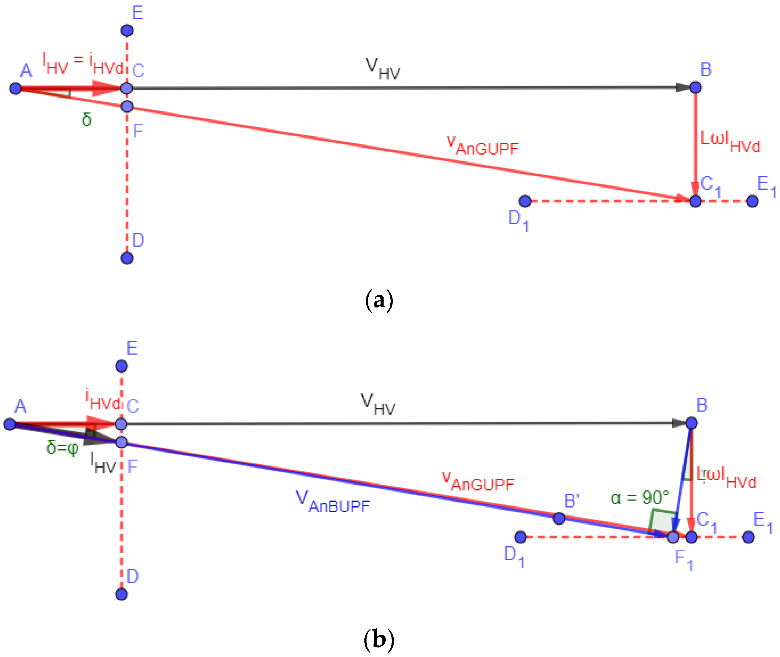
3.1. Normal Operation: Grid Unity Power Factor Operation (GUPF)

In normal operation, a power factor equal to unity is established in the HV terminals connected to the grid, meaning that the current demanded by the grid is in phase with the grid voltage (Figure 6a). If we neglect the losses of the converters and the resistance of the input filter (Lf), assuming a power efficiency of 100%, the power at the HV terminals will be equal to the sum of the power demanded by the loads connected in any of the output ports (Pj). Under this assumption, IHVd, the direct component of the current that is in phase with the grid voltage is the only current component as the unity power factor is achieved and the displacement angle between the grid current and the voltage, ϕ, is zero.
P H V = V H V I H V d = P j I H V = I H V d = P j V H V ; I H V q = 0 δ A B G U P F > φ = 0
Following the vector diagram depicted in Figure 6a, it can be obtained that
V A n = V H V 2 + ( L ω I H V ) 2 δ = arctan ( L ω I H V V H V )
Considering an efficiency of 100%, the power demanded by the port j of the MPST is given by
P j = V P E B i j I H V cos δ ,
and the total power by
P H V = V H V I H V d = P j = ( V P E B i j ) I H V cos δ = V A n I H V cos δ ,
thus, the required PEB input voltage can be determined as
V P E B i j = P j I H V cos δ = P j V P E B i j P j V A n P j P j .  
It is assumed that the output DC voltage of the input side converter of every PEB (VDCj) is properly controlled and is the same for all PEBs, and is equal to an established reference value (VDcref)
V D C j = V D C r e f ;   j
and Equations (10) and (11), the amplitude modulation index and the modulator wave phase (that should be used in the PWM sinusoidal strategy used for controlling the H-bridge topology used in the synchronous rectifier at the PEB input side [14]) are given by
m a j = 2 V P E B i j V D C r e f = 2 V A n V D C r e f P j P j δ = arctan ( L ω V H V 2 P j )

3.2. Extended Operation with PEB Unity Power Factor Operation (BUPF)

In another potential operation, named in this paper as an extended operation, a power factor equal to unity is established in all PEBs (Figure 6b), this being the voltage and current at the input terminals of each PEB in phase. In this case the current at the HV terminals is no longer in phase with the HV voltage, and direct and quadrature grid current components are not zero. If losses are neglected as previously supposed, a power efficiency of 100% is achieved and power at the HV terminals will be equal to the sum of the power demanded by the loads connected in the output ports (Pj), achieving
P H V = V H V I H V d = P J I H V d = P j V H V ; I H V q 0
In this case the current, as it is not in phase with the HV voltage, is given by
I H V = I H V d cos φ = P j V H V cos φ
and the voltage that should be produced by all the PEBs connected in series, following the vectorial diagram shown in Figure 6b, is given by
V P E B i j = V A n = V H V 2 ( L ω I H V ) 2 δ = φ
This vectorial diagram can also determine that
sin φ = L ω I H V V H V = L ω V H V ( P j V H V cos φ ) sin φ · cos φ = 1 2 sin 2 φ = L ω V H V 2 P j   .
Following a similar analysis of that in the previous section, the amplitude modulation index and modulator wave phase (to be used in the PWM sinusoidal strategy in the input converter of PEB) can be obtained as
m a j = 2 V P E B i j V D C r e f = 2 V A n V D C r e f P j P j δ = φ = 1 2 arcsin ( 2 L ω V H V 2 P j )
Theoretically, Van in the BUPF is lower than in the GUPF (comparing vector modules in Figure 6a,b), having, for the same output powers Pj, a wider or extended operation as the saturation region (maj > 1) is reached in more unbalanced or extreme conditions. In practical cases, as the input filter impedances are usually small, it results that
2 L ω V H V 2 P j 0     arcsin ( 2 L ω V H V 2 P j ) 2 L ω V H V 2 P j δ B U P F = φ = 1 2 ( 2 L ω V H V 2 P j ) δ G U P F ,
with both operations’ strategies producing similar results.

3.3. Extended Operation Using Reactive Power (ERPO)

If powers Pj in the ports are very different, the amplitude modulation indexes maj given by (20) will also be very different, and the maximum value of maj will easily have values greater than 1, being the corresponding PEB operating in the overmodulation zone. In these conditions, a variation is proposed with the main aim of extending the PWM sinusoidal lineal operation in the PEBs.
Following Equation (20), a scale factor can be determined by
S F = max ( m a j ) = max ( 2 V A n V D C r e f P j P j ) = 2 V A n V D C r e f 1 P j max ( P j )
and applied to this equation to prevent the overmodulation region and to ensure that the maximum maj will be equal to 1, and obtaining
m a j = 1 S F 2 V A n V D C r e f P j P j = P j max ( P j )
The voltage at the input terminals of the MPST will be given by
V A n = V P E B i j = ( m a j V D C r e f 2 ) = ( P j max ( P j ) V D C r e f 2 ) = V D C r e f 2 max ( P j ) P j
and the phase angle of the modulation waveforms can be obtained from Figure 6c and Equation (17) as
δ = arcsin ( L ω I H V d V A n ) = arcsin ( L ω V A n P j V H V )
Once δ is known, the quadrature grid current component can be determined as
I H V q = I H V sen φ = V H V V A n cos δ L ω
and current displacement phase, ϕ, can be obtained from Equations (17) and (30)
φ = arctan ( I H V q I H V d ) = arctan ( V H V ( V H V V A n cos δ ) L ω P j )
Combining Equations (27)–(29) to summarize the analysis performed in this section, the main equations to be used to control the system with this operation strategy are
m a j = P j max ( P j ) δ = arcsin ( L ω I H V d V A n ) = arcsin ( 2 L ω V D C r e f V H V max ( P j ) )

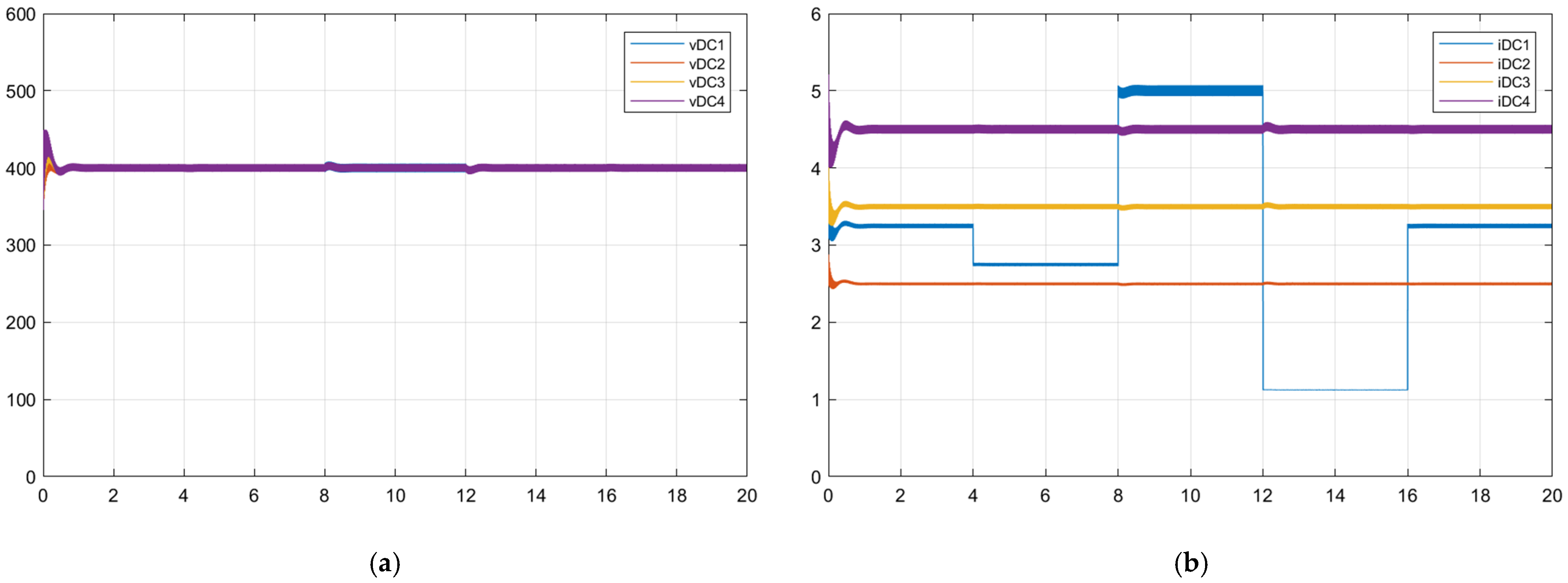
4. Analysis of Operation

In this section, the analysis of an MPST when using the different operation modes described in the previous section is made. The studied MPST has four ports, each of them conformed by a single PEB and the analysis is conducted by a simulation using the average models described in Section 2. It should be highlighted that the control block includes a proportional–integral controller to control the quadrature current component, to compensate for the parasitic effects not considered in the theoretical analysis conducted in Section 3; mainly, the series resistance of the filter inductor.
The overall high-level scheme in MATLAB/Simulink is shown in Figure 7, being structured in four main simulation blocks: grid and synchronization, PEB models, and control and visualization blocks. The main parameters and magnitudes used in the simulation are detailed in Table 2. To highlight the limits of the operation achieved under the different modes, four cases are considered, changing the HV grid voltage (VHV) and a changing output power sequence is considered in port 1.

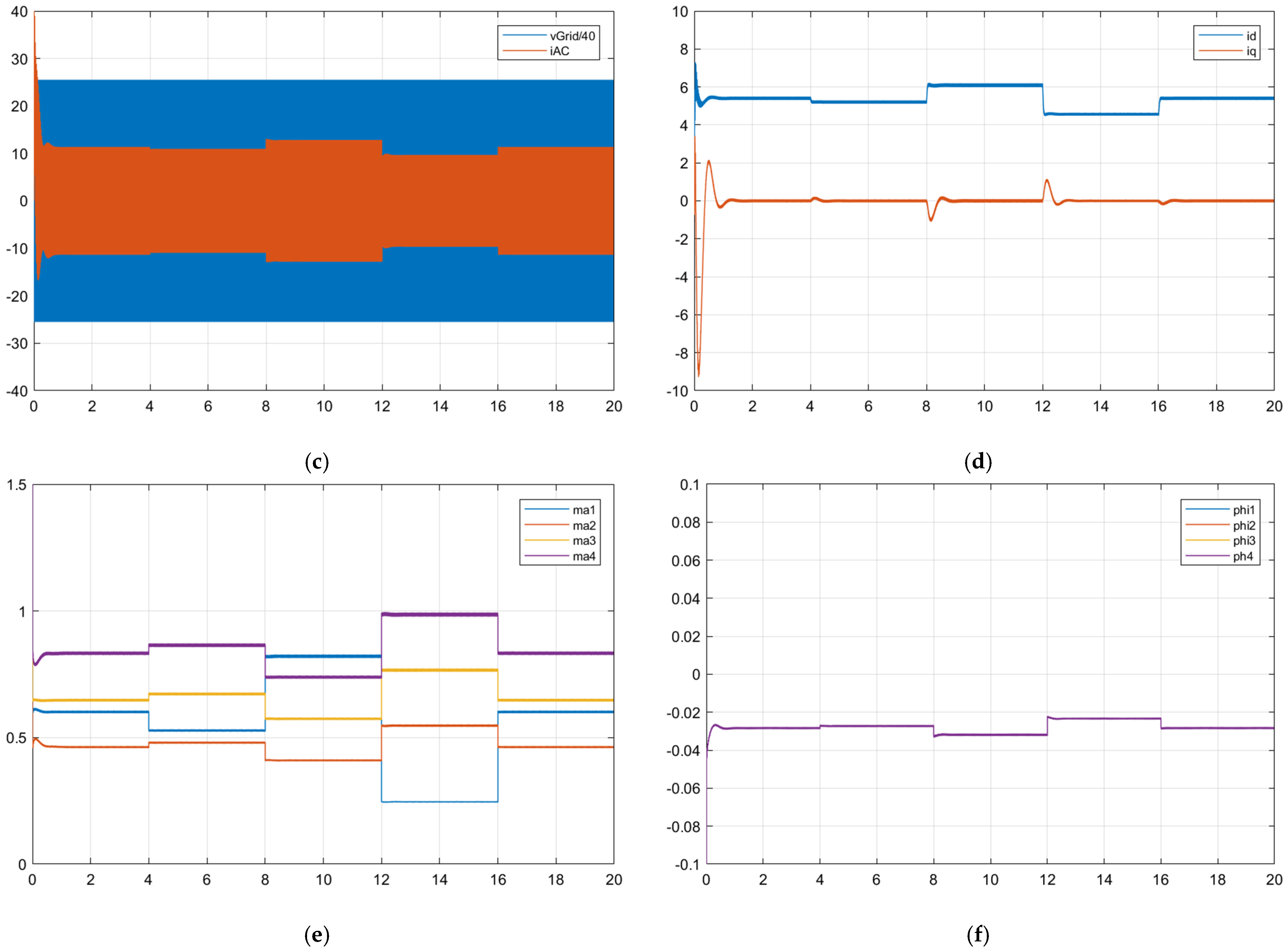
4.1. Operation with GUPF

If the first operation mode is applied, aiming to achieve a grid unity power factor, two simulations are conducted, considering cases A and B, to show the limits of this operation mode and to compare with the alternatives proposed to extend the operation possibilities.
The results for the case A (when grid voltage is 1250 V) show that the operation strategy works in a right way controlling the output DC voltage in the PEBs to follow the established reference of 400 V (Figure 8a) and supplying the current to the loads corresponding to the given output power (Figure 8b). In Figure 8c grid voltage and current voltage are shown being possible to see how the grid current amplitude is adjusted according to the output power conditions. Figure 8d validates that only the direct current component is changing according to the output power, and that the quadrature components is cero in steady conditions as established in this operation mode, achieving the desired GUPF goal.
In Figure 8e it can be seen that all the amplitude modulation index are bello 1, and all PEB are operating in the PWM sinusoidal lineal zone. Finally, Figure 8f shows the modulation waves phase that changes also depending on the output power.
In this operation mode, if case B is considered (and grid voltage is 1300 V), the MPST is operating in the right mode until the power in port #1 (PEB #1) changes to 450 W (time between 12 s and 16 s). This low output power value produces an amplitude modulation index of PEB #4 that should be greater than 1 and activates the control to prevent the operation in the overmodulation zone. During this interval (12–16 s) the MPST is not controlled properly and the DC voltage is not following the reference value (Figure 9a), causing the rest of the modules to also be out of control (Figure 9).

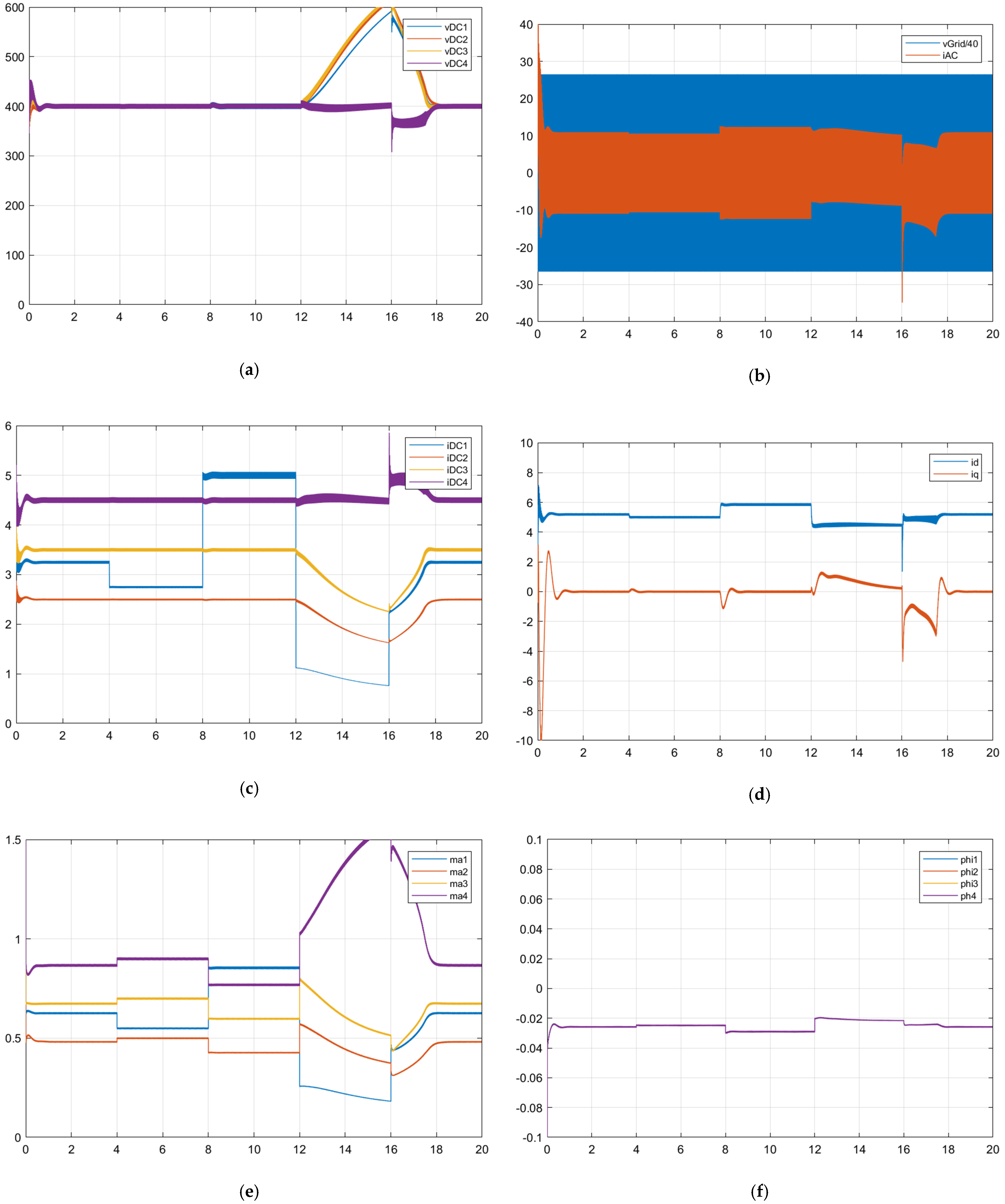
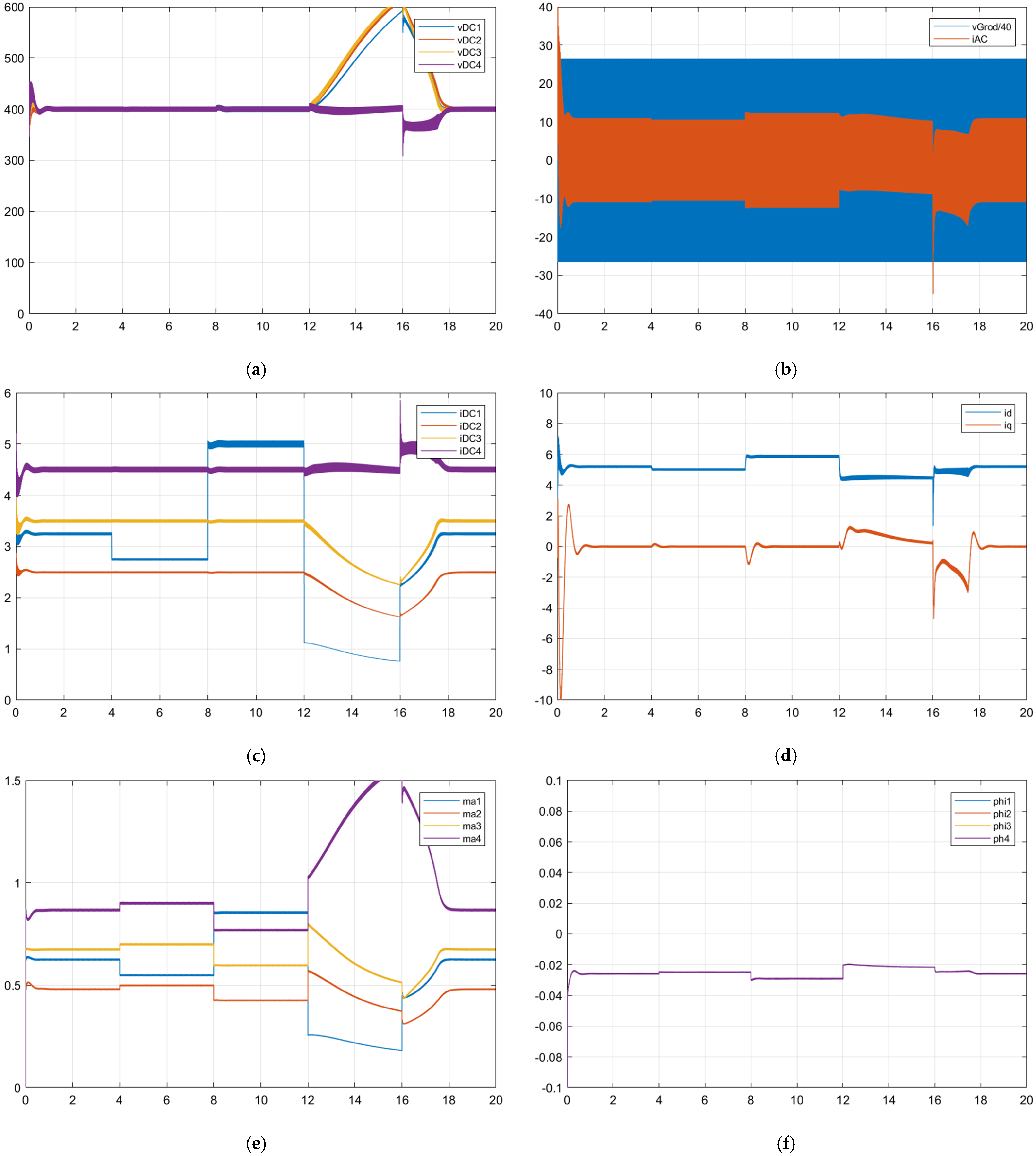
4.2. Operation with BUPF

The results of the MPST when using the BUPF operation are summarized in Figure 10. In this operation mode, only case B is considered (grid voltage is 1300 V), and, as in previous case, the MPST operates correctly until the power in port #1 (PEB #1) changes to 450 W (time between 12 s and 16 s). This low output power has the same effect on the DC voltage as the previous operation mode, so that, during this interval (12–16 s), the MPST is not controlled properly and the DC voltage is not following the reference value (Figure 10a), causing the rest of the values to also be out of control (Figure 10).
In conclusion, the change from operating as a GUPF to BUPF has no practical effect on the control of the MPST as the impedance of the filter inductors produces a low drop voltage compared with the grid voltage, and the modulation waveform phase is very small, being that GUPF and BUPF are similar strategies, as obtained from Equation (25). The results could be different as a filter inductor is intentionally selected to have a significant impedance at grid frequency.

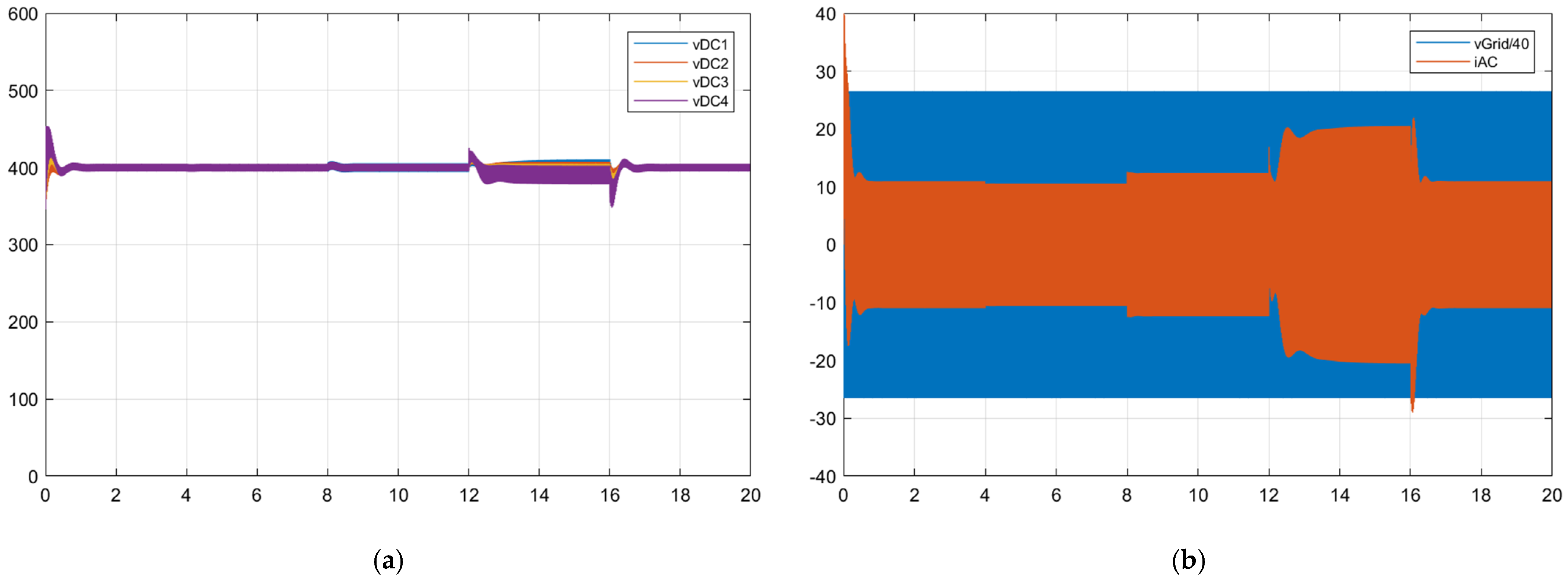
4.3. Operation with ERCO

Figure 11 shows the results when using operation ERCO in case B conditions (grid voltage equal to 1300). The MPST operates properly in all simulation times, even in the period between 12 s and 16 s when previous operation strategies failed to control the system. It can be seen (Figure 11e) that during this interval, the maximum amplitude modulation index (ma4) is fixed to 1 by controlling the quadrature current component (Figure 11d) that obtains a value close to 10A. For the rest of the simulation time, no reactive power control is needed, as the amplitude modulation indexes are lower than 1, and the quadrature current components are zero.
It can be highlighted how, during the ERCO mode, the ripple in the capacitor voltage of the PEB for which the amplitude modulation index is fixed to 1, is significantly higher than in the rest of the operation time (Figure 11a).
To highlight even more the extended operation achieved with the ERCO strategy, case C (grid voltage equal to 1400 V) was simulated and the main results are shown in Figure 12. MPST is still operating properly, establishing the maximum amplitude modulation index (as in the previous case for PEB#4) during the interval from 12 to 16 s, being able to maintain the DC output voltage at the given reference value (400 V) and maintain the required output powers.
In this case it is notable that the performance of the system is not optimal, highlighting the big capacitor voltage ripple (at double the grid frequency) in PEB#4, which is also transmitted to the output current. It is also highlights the high value that the quadrature current component should have to keep the MPST under control.

5. Conclusions

This work has discussed the concept and basic design of the MPST, obtaining an average model of the input–PEB stages that allows the analysis of their operation when connected in series to an HV grid.
The main contributions of this work are the average models and the analysis of the proposed modular architecture for the MPST, where the different input converters are connected in series to the HV grid and are associated to different output ports. The proposed MPST has also been tested with a given power profile for the different output ports to validate the transient behavior and the right matching of the given reference DC voltage.
This work studied, by simulation, the operation of these input side converters when they are working at different powers, as the devices or resources connected to their corresponding output ports are consuming different powers.
In this situation, the converters are operating with different amplitude modulation indexes, and, if the difference between the working powers of the converters is high enough, the converters working at a higher power can enter into the PWM overmodulation zone.
Different operation strategies to control the series-connected PEBs were introduced and analyzed, paying attention to the cases when they operate at different powers. The results showed how if a reactive power control strategy is implemented, the right operation of the MPST can be extended, preventing PWM overmodulation and the systems becoming out of control.
The ERCO strategy demonstrated its possibility to extend the operation zone of the MPST but at the cost of increasing the DC voltage ripple and requiring higher current RMS values that could produce significant losses in filter inductors.
Future work will analyze the operation of PEBs with different modulation wave phases to optimize the MPST’s performance and how to control the DC voltage ripple when the MPST is operating with the ERCO strategy.
The proposed ERCO should be optimized in future work as not all the PEBs operating with the same DPF, so they can extend the operation to more severe cases when the unbalanced operation of the different ports is higher; it being possible that some of them operate with positive power (they consume power, loads), others with negative power (they are producing, such as photovoltaic modules) and others could have either positive or negative power (they are energy storage systems that can be charged or discharged).

Author Contributions

Conceptualization, E.R.-C.; methodology, E.R.-C. and E.G.-R.; validation, E.R.-C. and C.R.-C.; formal analysis, E.R.-C. and E.G.-R.; investigation, E.R.-C. and M.-I.M.-M.; writing—original draft preparation, E.R.-C.; writing—review and editing, E.R.-C., F.B.-G., E.G.-R. and C.R.-C.; project administration and funding acquisition, E.R.-C. All authors have read and agreed to the published version of the manuscript.

Funding

This research was funded by Junta de Extremadura (Regional Government) and European Regional Development Fund (ERDF), under grant IB18067.

Institutional Review Board Statement

Not applicable.

Conflicts of Interest

The authors declare no conflict of interest. The funders had no role in the design of the study; in the collection, analyses, or interpretation of data; in the writing of the manuscript, or in the decision to publish the results.

References

  1. Costa, L.F.; De Carne, G.; Buticchi, G.; Liserre, M. The Smart Transformer: A solid-state transformer tailored to provide ancillary services to the distribution grid. IEEE Power Electron. Mag. 2017, 4, 56–67. [Google Scholar] [CrossRef] [Green Version]
  2. Zhao, X.; Li, B.; Fu, Q.; Mao, S.; Xu, D.G.; Leon, J.I.; Franquelo, L.G. DC Solid State Transformer Based on Three-Level Power Module for Interconnecting MV and LV DC Distribution Systems. IEEE Trans. Power Electron. 2021, 36, 1563–1577. [Google Scholar] [CrossRef]
  3. Ronanki, D.; Williamson, S.S. Modular Multilevel Converters for Transportation Electrification: Challenges and Opportunities. IEEE Trans. Transp. Electrif. 2018, 4, 399–407. [Google Scholar] [CrossRef]
  4. Chen, H.; Divan, D. Soft-Switching Solid-State Transformer (S4T). IEEE Trans. Power Electron. 2018, 33, 2933–2947. [Google Scholar] [CrossRef]
  5. Chen, P.; Liu, J.; Xiao, F.; Zhu, Z.; Huang, Z.; Ren, Q. Optimal Phase-Shifted Modulation Method for Suppressing the Current Ripple of Modular Multilevel Converter-Bidirectional DC–DC Converter Under Unbalanced Operation. IEEE J. Emerg. Sel. Top. Power Electron. 2022, 10, 690–703. [Google Scholar] [CrossRef]
  6. Younis, T.; Mattavelli, P.; Magnone, P.; Toigo, I.; Corradin, M. Enhanced Level-Shifted Modulation for a Three-Phase Five-Level Modified Modular Multilevel Converter (MMC). IEEE J. Emerg. Sel. Top. Power Electron. 2022, 10, 704–716. [Google Scholar] [CrossRef]
  7. Chen, J.; Jiang, D.; Sun, W.; Pei, X. Common-Mode Voltage Reduction Scheme for MMC With Low Switching Frequency in AC–DC Power Conversion System. IEEE Trans. Ind. Inform. 2022, 18, 278–287. [Google Scholar] [CrossRef]
  8. Marquez, A.; Leon, J.I.; Vazquez, S.; Franquelo, L.G.; Kouro, S. Adaptive phase-shifted PWM for multilevel cascaded H-bridge converters with large number of power cells. In Proceedings of the 2017 11th IEEE International Conference on Compatibility, Power Electronics and Power Engineering (CPE-POWERENG), Cadiz, Spain, 4–6 April 2017; pp. 430–435. [Google Scholar] [CrossRef]
  9. Cai, Y.; Gu, C.; Yang, J.; Li, J.; Buticchi, G.; Zhang, H. An Advanced Extended Phase Shift Modulation Strategy of Dual Active Bridge Converter Considering Magnetizing Inductance. In Proceedings of the IECON 2021—47th Annual Conference of the IEEE Industrial Electronics Society, Toronto, ON, Canada, 13–16 October 2021; pp. 1–6. [Google Scholar] [CrossRef]
  10. Monopoli, V.G.; Marquez, A.; Leon, J.I.; Liserre, M.; Buticchi, G.; Franquelo, L.G.; Vazquez, S. Applications and Modulation Methods for Modular Converters Enabling Unequal Cell Power Sharing: Carrier Variable-Angle Phase-Displacement Modulation Methods. IEEE Ind. Electron. Mag. 2021, 16, 19–30. [Google Scholar] [CrossRef]
  11. Marquez, A.; Monopoli, V.G.; Tcai, A.; Leon, J.I.; Buticchi, G.; Vazquez, S.; Liserre, M.; Franquelo, L.G. Discontinuous-PWM Method for Multilevel N-Cell Cascaded H-Bridge Converters. IEEE Trans. Ind. Electron. 2021, 68, 7996–8005. [Google Scholar] [CrossRef]
  12. Bute, P.R.; Mittal, S.K. Simulation Study of Cascade H-bridge Multilevel Inverter 7-Level Inverter by SHE Technique. In Proceedings of the 2020 Fourth International Conference on Computing Methodologies and Communication (ICCMC), Erode, India, 11–13 March 2020; pp. 670–674. [Google Scholar] [CrossRef]
  13. Sanjay, P.S.; Tanaji, P.R.; Patil, S. Symmetrical Multilevel Cascaded H-Bridge Inverter Using Multicarrier SPWM Technique. In Proceedings of the 2018 3rd International Conference for Convergence in Technology (I2CT), Pune, India, 6–8 April 2018; pp. 1–4. [Google Scholar] [CrossRef]
  14. Maurya, S.; Mishra, D.; Singh, K.; Mishra, A.K.; Pandey, Y. An Efficient Technique to reduce Total Harmonics Distortion in Cascaded H- Bridge Multilevel Inverter. In Proceedings of the 2019 IEEE International Conference on Electrical, Computer and Communication Technologies (ICECCT), Coimbatore, India, 20–22 February 2019; pp. 1–5. [Google Scholar] [CrossRef]
  15. Sanchez-Cruz, S.; Romero-Cadaval, E.; Cabrera, B.M.; Romera, E.G.; Montero, M.I.M.; Gonzalez, F.B. Modulation strategy and control of Modular Cascade H-Bridge Converters as Input-side of a Multi-port Smart Transformer. In Proceedings of the 2021 22nd IEEE International Conference on Industrial Technology (ICIT), Valencia, Spain, 10–12 March 2021; pp. 1320–1325. [Google Scholar] [CrossRef]
  16. IRoasto, I.; Romero-Cadaval, E.; Martins, J.; Smolenski, R. State of the art of active power electronic transformers for smart grids. In Proceedings of the IECON 2012—38th Annual Conference on IEEE Industrial Electronics Society, Montreal, QC, Canada, 25–28 October 2012; pp. 5241–5246. [Google Scholar] [CrossRef]
  17. Cabrera, B.M.; Cadaval, E.R.; Cruz, S.S.; Montero, M.I.M.; Romera, E.G.; Gonzalez, F.B. Control of modular multilevel converter as input side of a smart transformer. In Proceedings of the 2021 IEEE 15th International Conference on Compatibility, Power Electronics and Power Engineering (CPE-POWERENG), Florence, Italy, 14–16 July 2021; pp. 1–7. [Google Scholar] [CrossRef]
  18. Zhuang, Y.; Liu, F.; Huang, Y.; Wang, S.; Pan, S.; Zha, X.; Diao, X. A Multi-port DC Solid-state Transformer for MVDC Integration Interface of Multiple Distributed Energy Sources and DC Loads in Distribution Network. IEEE Trans. Power Electron. 2022, 37, 2283–2296. [Google Scholar] [CrossRef]
  19. Hazra, S.; Bhattacharya, S.; Chakraborty, C. A novel control principle for a high frequency transformer based multiport converter for integration of renewable energy sources. In Proceedings of the IECON 2013—39th Annual Conference of the IEEE Industrial Electronics Society, Vienna, Austria, 10–13 November 2013; pp. 7984–7989. [Google Scholar] [CrossRef]
  20. Zheng, L.; Marellapudi, A.; Chowdhury, V.R.; Bilakanti, N.; Kandula, R.P.; Saeedifard, M.; Grijalva, S.; Divan, D. Solid-State Transformer and Hybrid Transformer with Integrated Energy Storage in Active Distribution Grids: Technical and Economic Comparison, Dispatch, and Control. IEEE J. Emerg. Sel. Top. Power Electron. 2022, 1. [Google Scholar] [CrossRef]
  21. Zhao, T.; Wang, G.; Bhattacharya, S.; Huang, A.Q. Voltage and Power Balance Control for a Cascaded H-Bridge Converter-Based Solid-State Transformer. IEEE Trans. Power Electron. 2013, 28, 1523–1532. [Google Scholar] [CrossRef]
  22. Zhang, Z.; Zhao, H.; Fu, S.; Shi, J.; He, X. Voltage and power balance control strategy for three-phase modular cascaded solid stated transformer. In Proceedings of the 2016 IEEE Applied Power Electronics Conference and Exposition (APEC), Long Beach, CA, USA, 20–24 March 2016; pp. 1475–1480. [Google Scholar] [CrossRef]
  23. Ko, Y.; Andresen, M.; Buticchi, G.; Liserre, M. Power Routing for Cascaded H-Bridge Converters. IEEE Trans. Power Electron. 2017, 32, 9435–9446. [Google Scholar] [CrossRef] [Green Version]
  24. Zhao, T.; Chen, D. A Power Adaptive Control Strategy for Further Extending the Operation Range of Single-Phase Cascaded H-Bridge Multilevel PV Inverter. IEEE Trans. Ind. Electron. 2022, 69, 1509–1520. [Google Scholar] [CrossRef]
  25. Wang, C.; Chen, M.; Jie, Y. A Reactive Power Control Optimization Scheme for the Power Imbalance of Cascaded Photovoltaic Converter. In Proceedings of the 2021 IEEE Energy Conversion Congress and Exposition (ECCE), Vancouver, BC, Canada, 10–14 October 2021; pp. 123–129. [Google Scholar] [CrossRef]
Figure 1. (a) Conventional topology of a three-phase smart transformer [1], (b) possible topology of a multi-port smart transformer.
Energies 15 03778 g001
Figure 2. Possible topologies for multi-port smart transformer: (a) [18], (b) [19].
Energies 15 03778 g002
Figure 3. Solid state transformer (SST) and the hybrid transformer (HT) with integrated storage in active distribution grids [19]. (a) Line frequency transformer. (b,c) SST. Both the three stage SST in (b) and the single stage current source SST in (c) can realize controllability and storage integration. (d) Energy storage. (e,f) HT. The converter in the HT can be installed either on (e) LV side or (f) MV side of the transformer.
Energies 15 03778 g003
Figure 4. Simplified model to analyze the input port connection.
Energies 15 03778 g004
Figure 5. Model of a single PEB: (a) averaged model of PEB assuming null losses and efficiency of 100%, (b) PEB hierarchical view with input ports and output ports and given output power profile.
Energies 15 03778 g005
Figure 6. Vectorial representation of possible operation modes for the input side of the MPST: (a) grid UPF operation, (b) PEB UPF operation, (c) extended operation using reactive power (ERPO).
Energies 15 03778 g006aEnergies 15 03778 g006b
Figure 7. Overall high-level scheme in MATLAB/Simulink of the simulated MPST composed of four PEBs: (a) grid model and series connection of PEB HV terminals, (b) PEB models, (c) control strategy block and (d) visualization block.
Energies 15 03778 g007
Figure 8. Simulation results when using normal operation (GUPF) strategy for case A: (a) PEB output DC voltage, (b) PEB output DC current, (c) grid voltage and current, (d) grid d–q current components, (e) PEB amplitude modulation index and (f) PEB modulation waveform phase.
Energies 15 03778 g008aEnergies 15 03778 g008b
Figure 9. Simulation results when using normal operation (GUPF) strategy for case B: (a) PEB output DC voltage, (b) PEB output DC current, (c) grid voltage and current, (d) grid d–q current components, (e) PEB amplitude modulation index and (f) PEB modulation waveform phase.
Energies 15 03778 g009
Figure 10. Simulation results when using extended operation (BUPF) strategy for case B: (a) PEB output DC voltage, (b) PEB output DC current, (c) grid voltage and current, (d) grid d–q current components, (e) PEB amplitude modulation index and (f) PEB modulation waveform phase.
Energies 15 03778 g010
Figure 11. Simulation results when using extended by reactive power operation (ERPO) strategy for case B: (a) PEB output DC voltage, (b) PEB output DC current, (c) grid voltage and current, (d) grid d–q current components, (e) PEB amplitude modulation index and (f) PEB modulation waveform phase.
Energies 15 03778 g011aEnergies 15 03778 g011b
Figure 12. Simulation results when using extended operation (ERCO) strategy for case C: (a) PEB output DC voltage, (b) PEB output DC current, (c) grid voltage and current, (d) grid d–q current components, (e) PEB amplitude modulation index and (f) PEB modulation waveform phase.
Energies 15 03778 g012aEnergies 15 03778 g012b
Table 1. Comparison of ST, conventional DAB-based multi-stage ST, and low-frequency transformer with a rectifier and an inverter when implementing a three-phase 480 V/50 kVA solid state transformer with a switching frequency of 15 kHz [4].
TopologyActive Device CountSoft-SwitchingDC CapsXFMR
Frequency
Device
V/I
Rating
Total Device IRMS RatingFault
Current
Efficiency
Soft-switching solid state transformer (SST)12 (main) +
2 (auxiliary)
Full range-15 kHz1 p.u./2 p.u.12 p.u.2 p.u.97.4%
DAB-based multi-stage SST20DC/DC only with a limited range215 kHz1 p.u./1 p.u.20 p.u.>10 p.u.93%
Low-frequency transformer with rectifier and inverter12No160 Hz1 p.u./1 p.u.12 p.u.>10 p.u.91.5%
Table 2. Parameters used for the simulation.
ParameterValue
Grid voltage phase–phase RMSCase A 1250 V
Case B 1300 V
Case C 1400 V
DC voltage in PEB output terminals400 V
PEB output capacitor1.5 mF
Filter InductorInductance10 mH
Resistance0.3 Ω
Output power PEB #1Given sequence
(1300, 1100, 2000, 450, 1300) W
Output power PEB #21000 W
Output power PEB #31400 W
Output power PEB #41800 W
Publisher’s Note: MDPI stays neutral with regard to jurisdictional claims in published maps and institutional affiliations.

