
Novel H6 Transformerless Inverter for Grid Connected Photovoltaic System to Reduce the Conduction Loss and Enhance Efficiency


Abstract
:1. Introduction
2. Novel H6 Transformerless Inverter
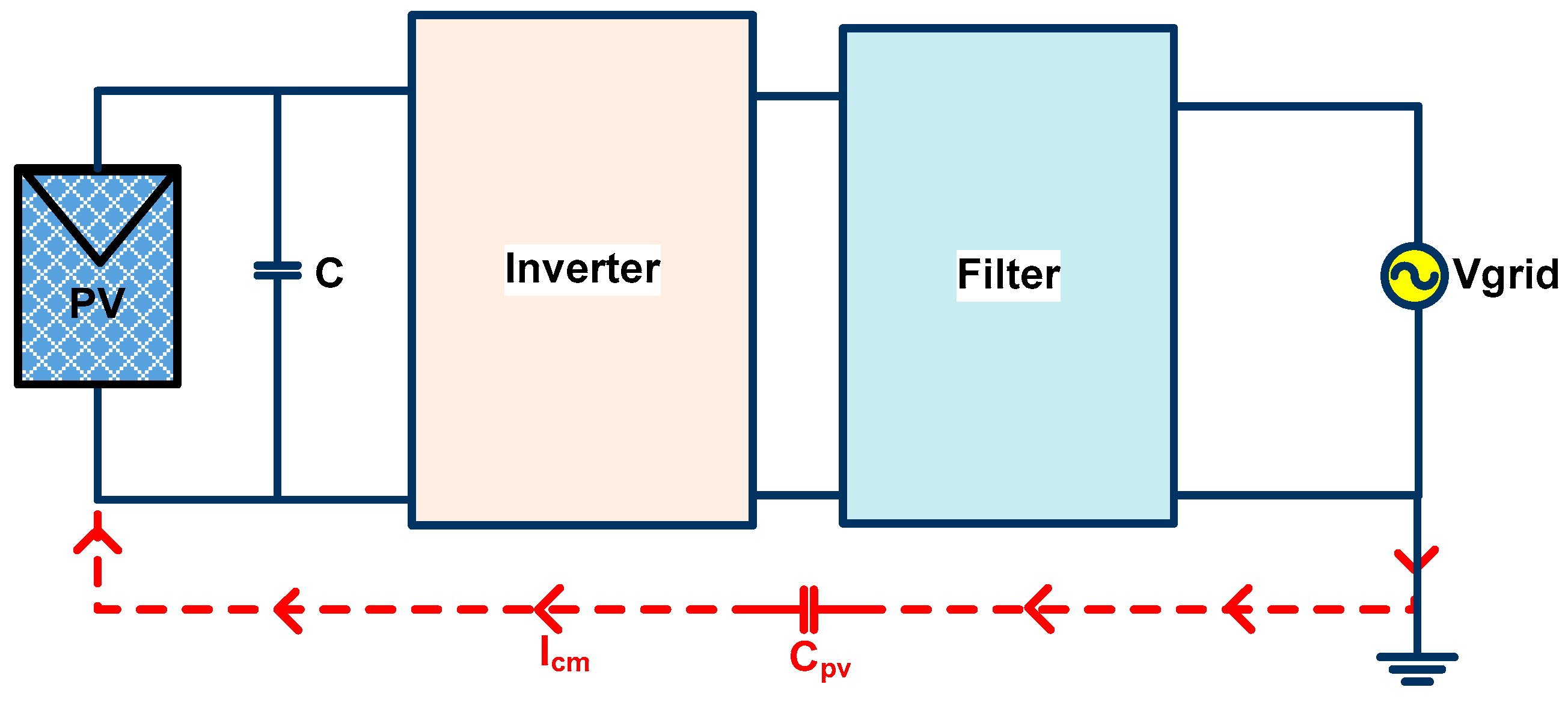
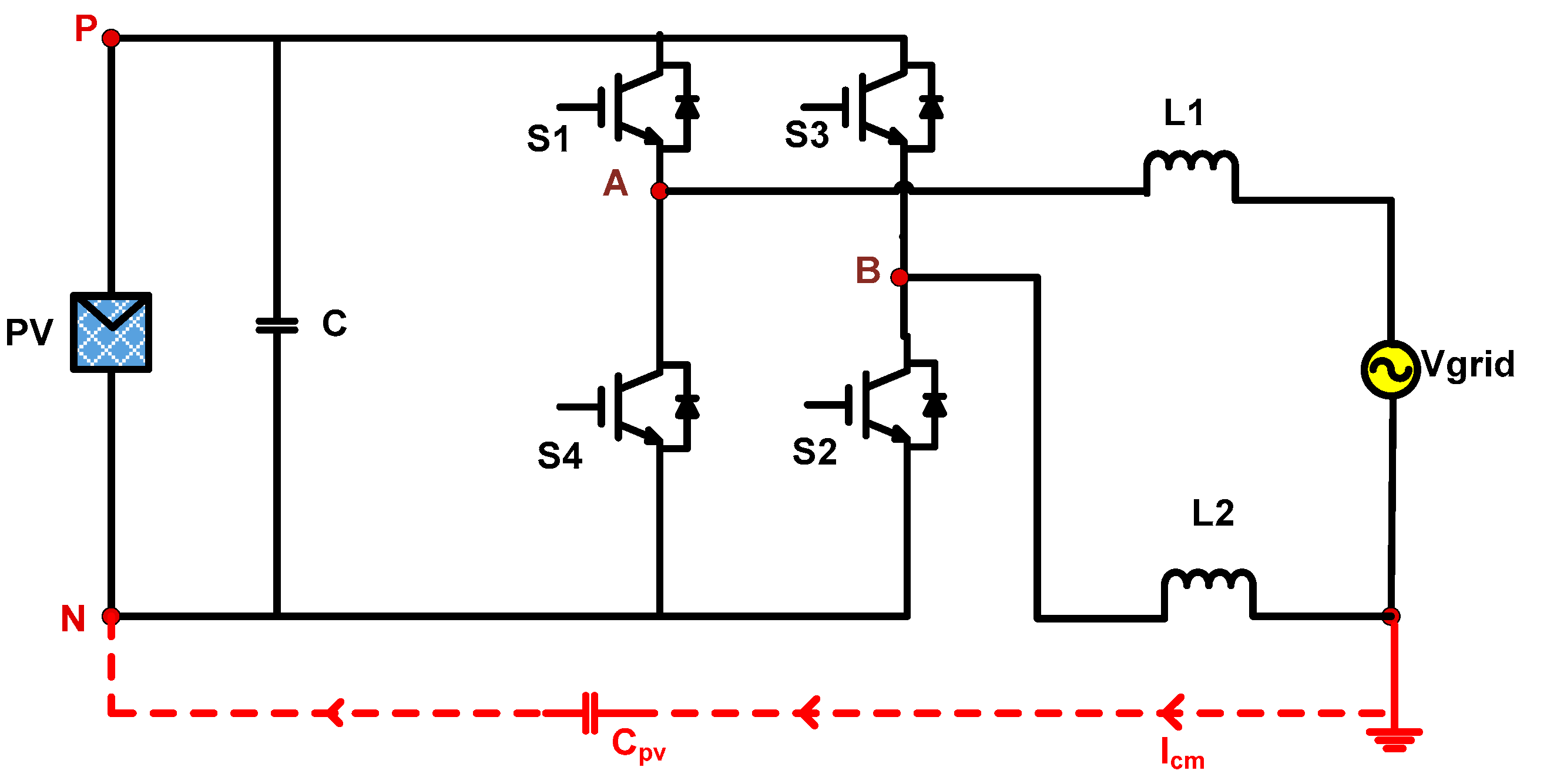
3. Leakage Current Analysis
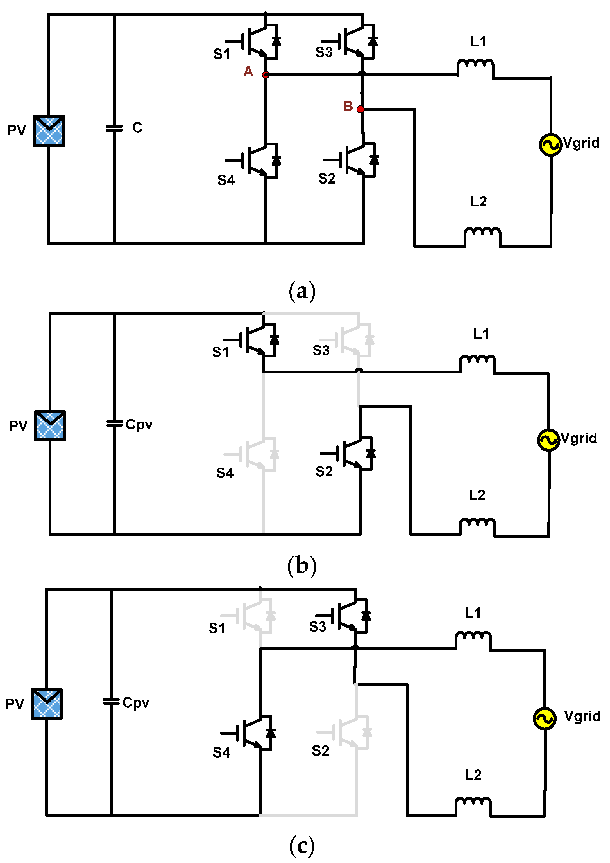
4. Performance Analysis of H4, H5 and H6 Inverters
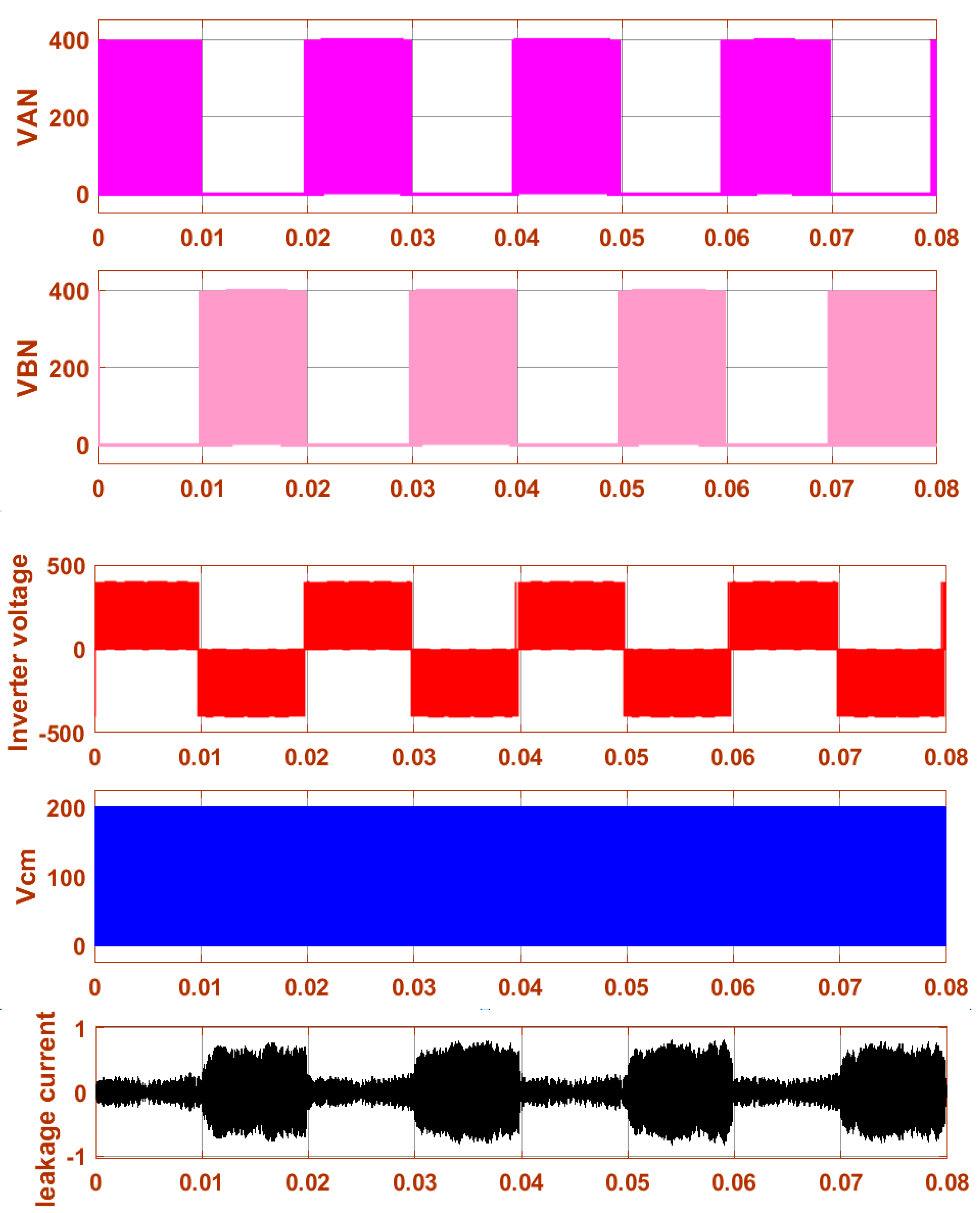
4.1. H4 Inverter
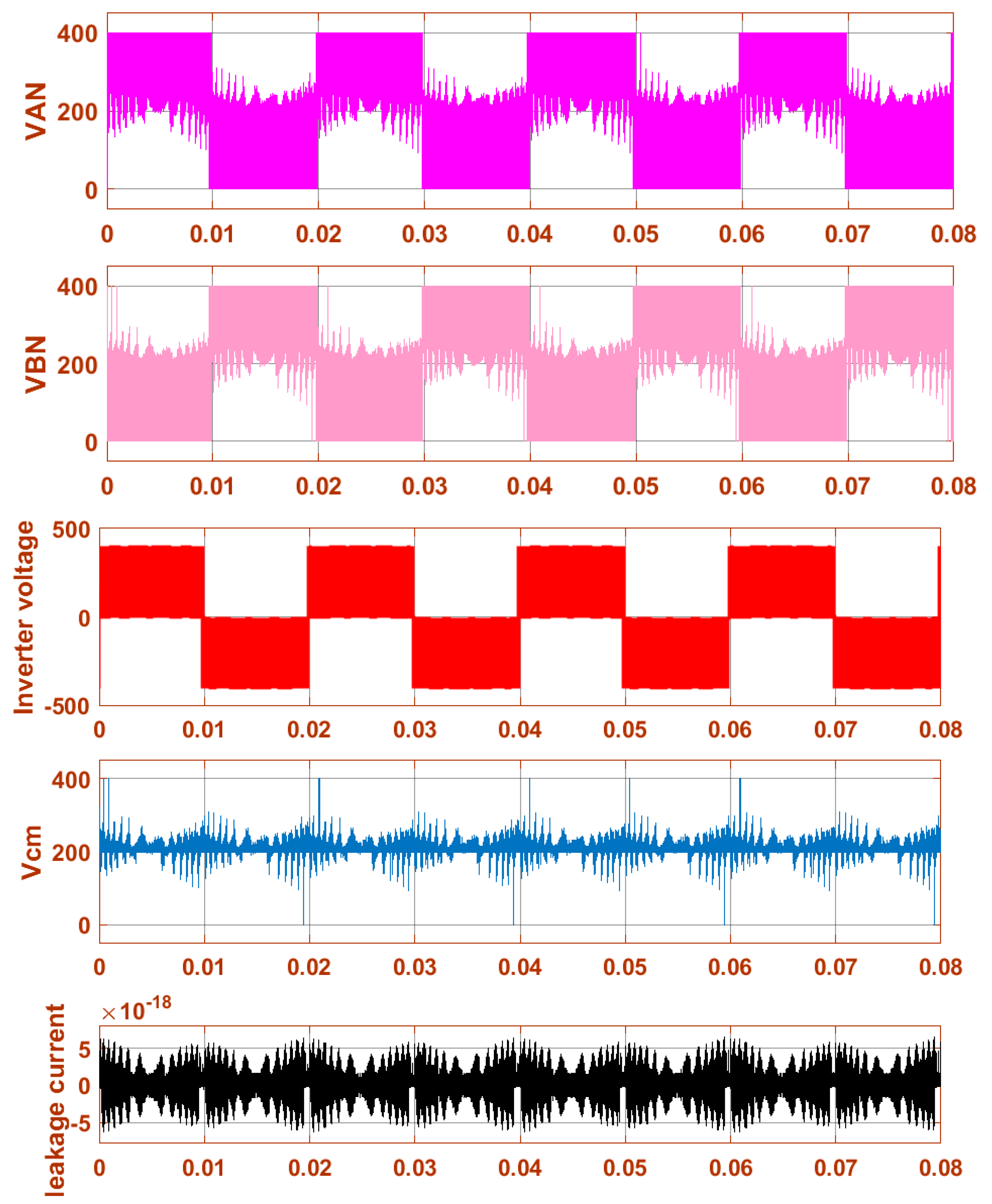
4.2. H5 Inverter
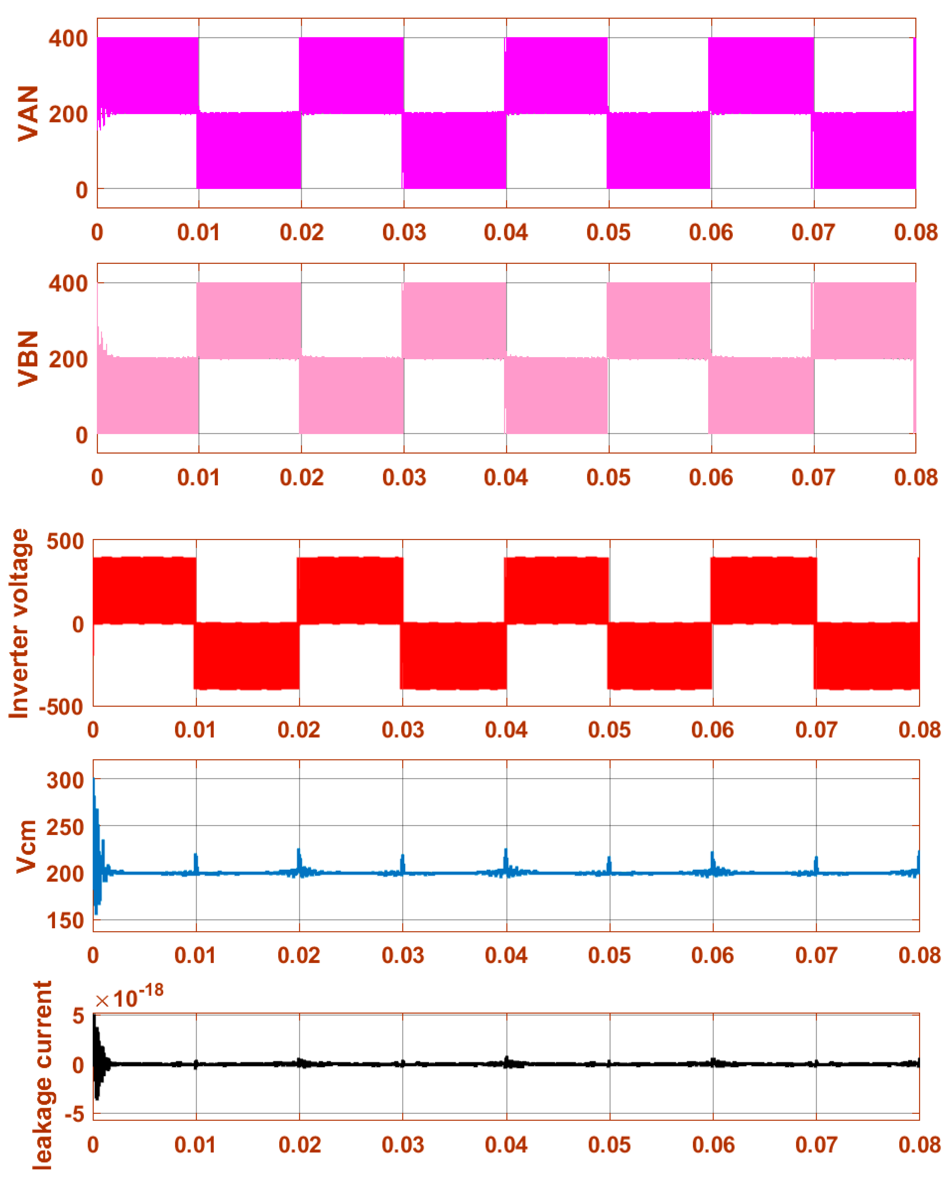
4.3. H6 I Inverter
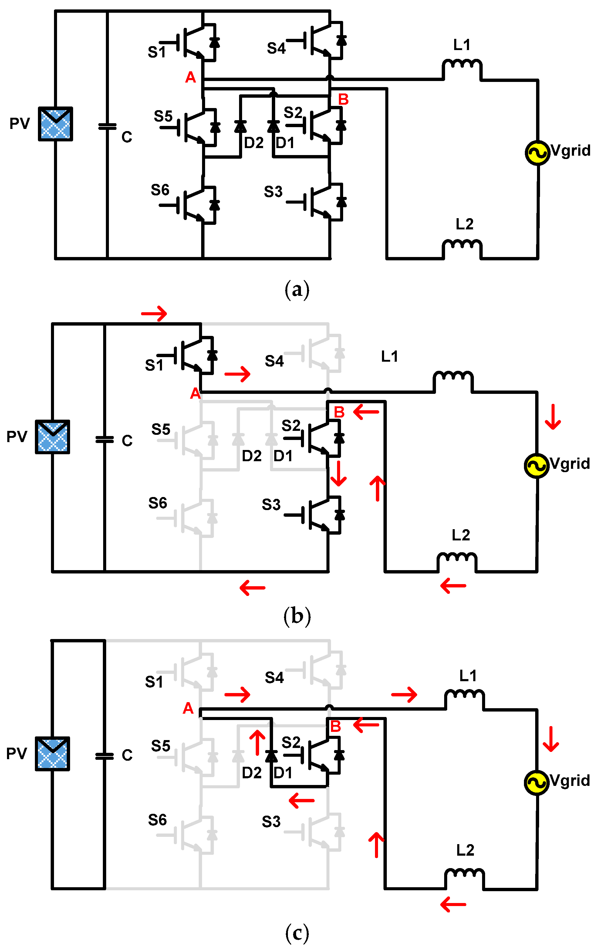
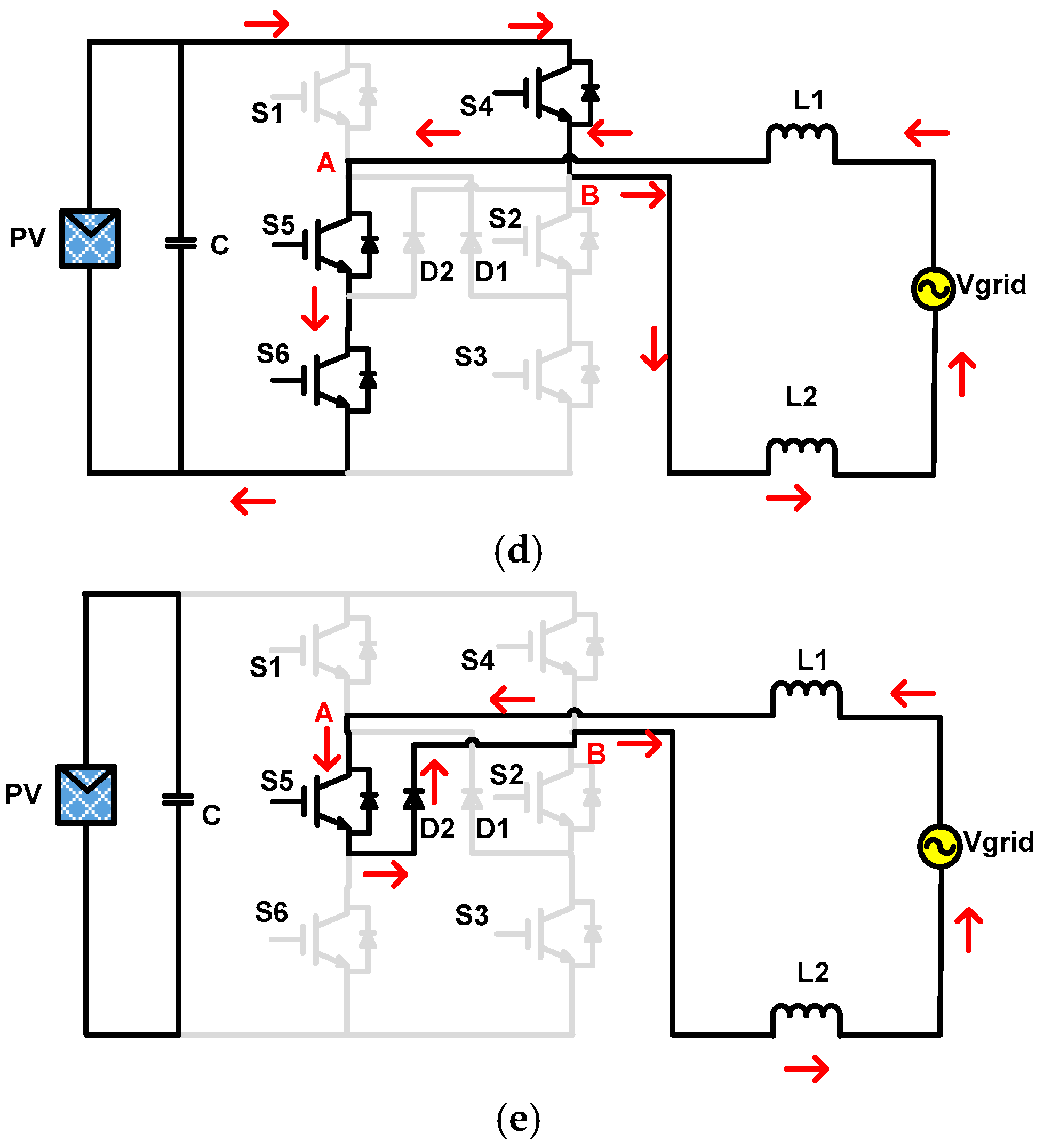
4.4. H6 II Inverter
4.5. H6 III Inverter
5. Analysis of Proposed Novel H6 Inverter
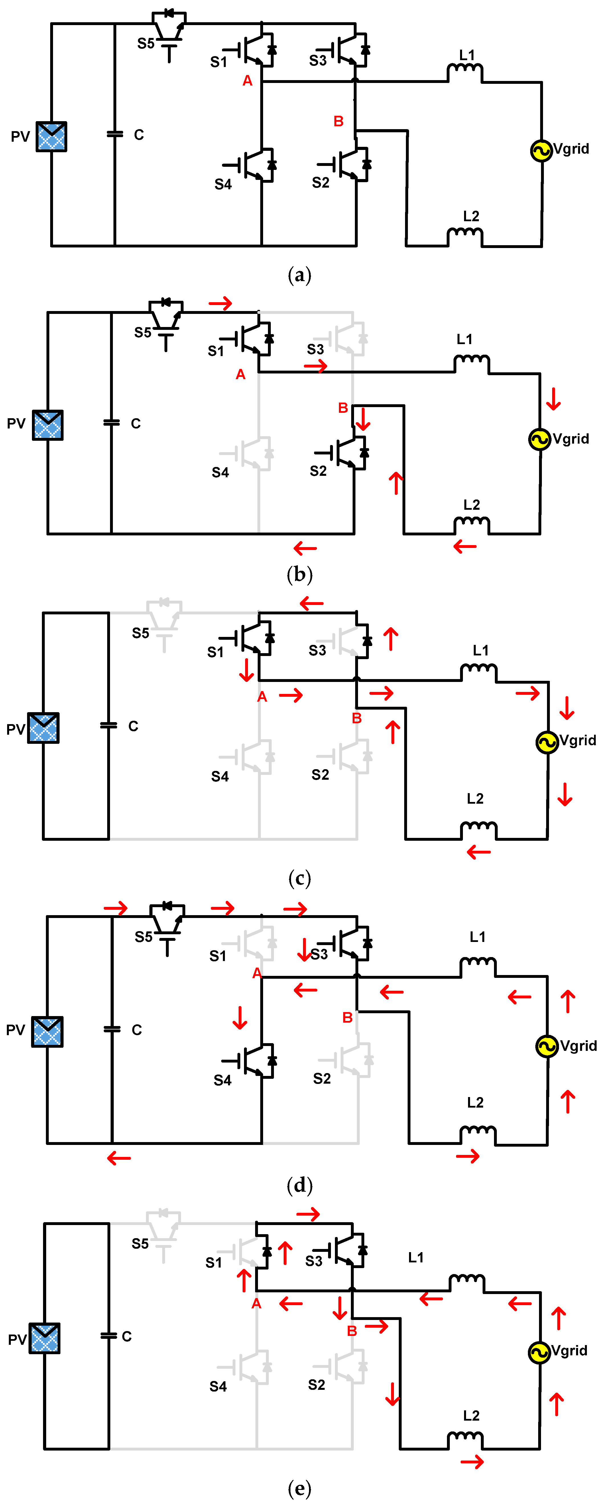
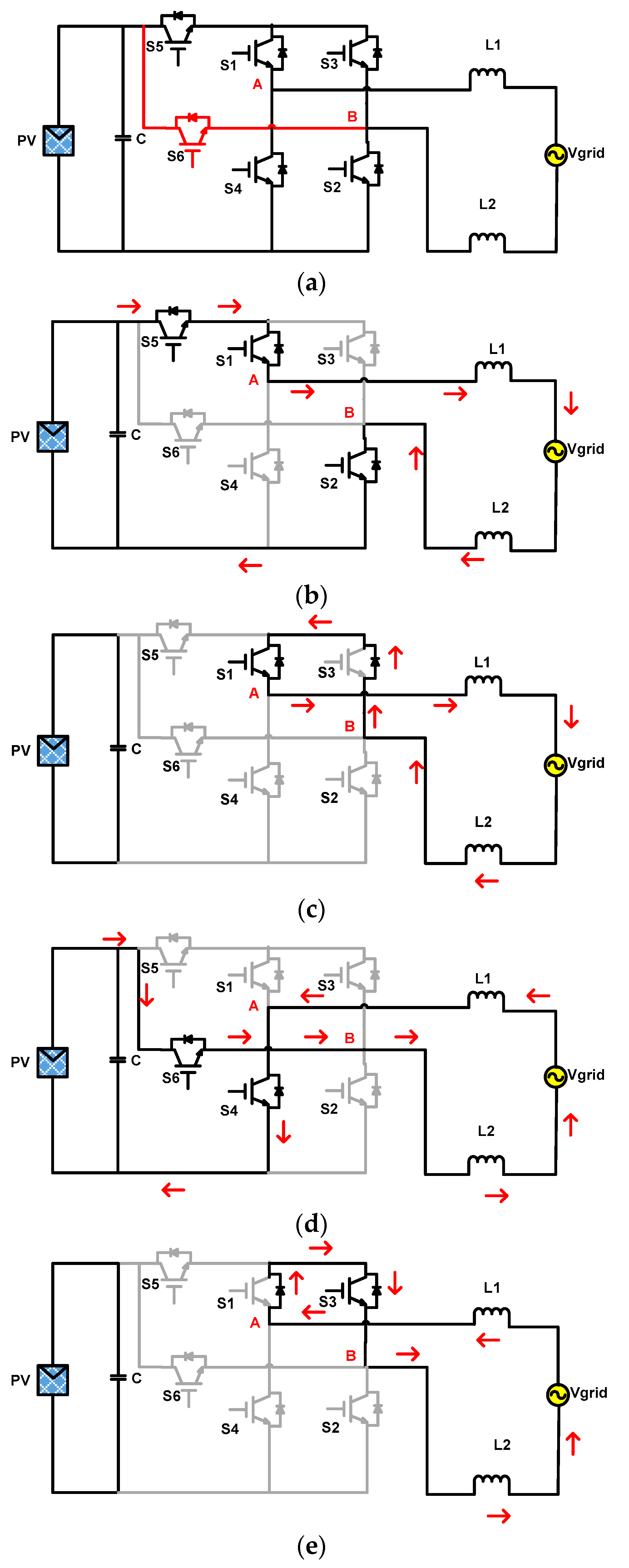
- (a)
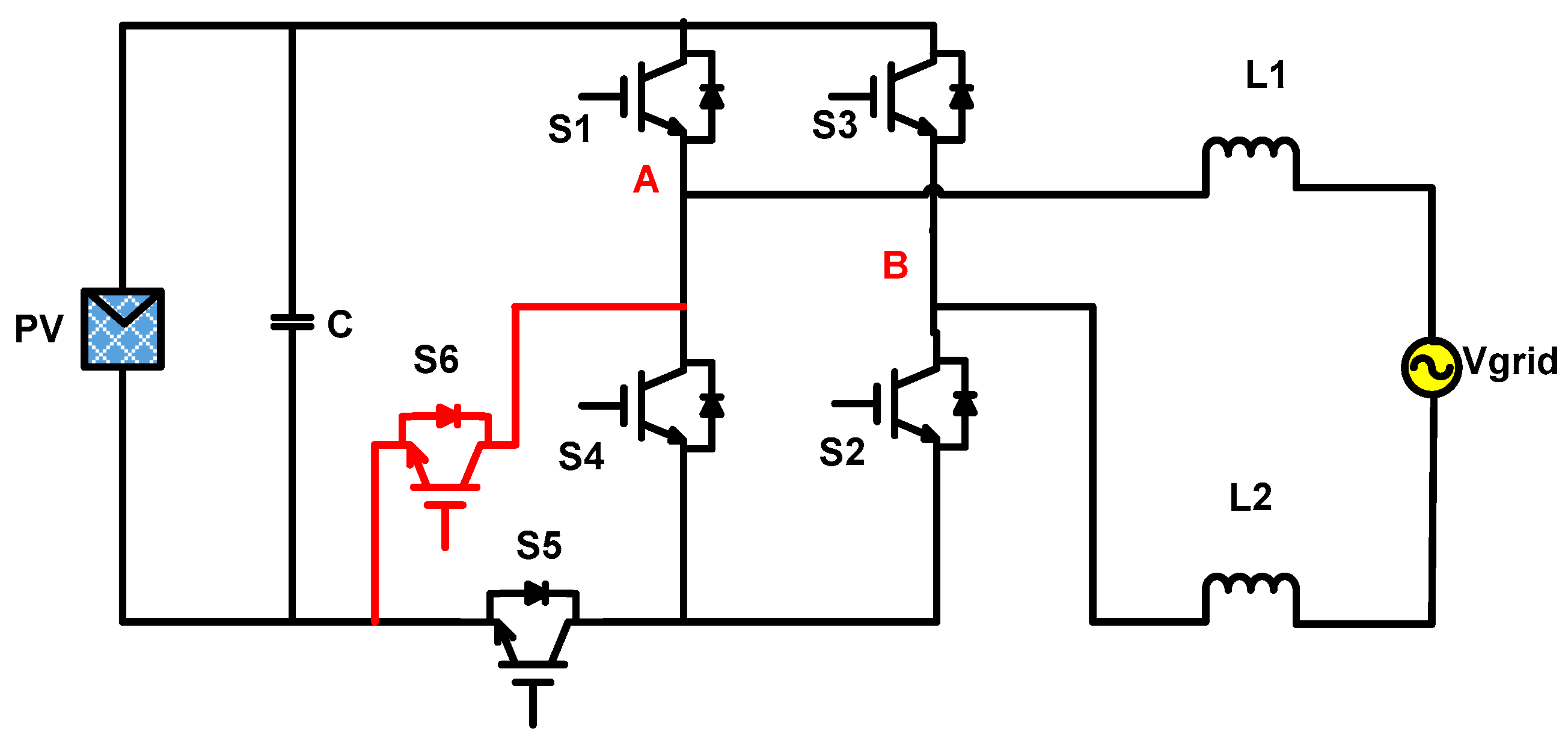
- Mode I: This mode is shown in Figure 10a. It represents the active mode in the positive half cycle of the grid voltage. Switches S1, S2 and S5 are turned on and the other switches are off. The inductor current thus flows through S1, S2 and S5 connecting the PV to the grid. Here, VAN = Vpv, VBN = 0. Therefore, Vcm = (VAN + VBN)/2 = Vpv/2.
- (b)
- Mode II: This mode is shown in Figure 10b. It represents the freewheeling mode in the positive half cycle of the grid voltage. S2 continues to remain on whereas S1 and S5 is turned off. The inductor current continues to flow in the same direction through S2 and antiparallel diode of S4. Here, VAN = VBN = Vpv/2. Therefore, Vcm = (VAN + VBN)/2 = Vpv/2.
- (c)
- Mode III: This mode is shown in Figure 10c. It represents the active mode in the negative half cycle of the grid voltage. S3 and S6 are turned on whereas other switches are off. The inductor current flows through S3 and S6. The conduction losses in this mode are less as compared to H5, H6 I and H6 III since only two switches are conducting. VAN = 0, VBN = Vpv. Therefore, Vcm = (VAN + VBN)/2 = Vpv/2.
- (d)
- Mode IV: This mode is shown in Figure 10d. It represents the freewheeling mode in the negative half cycle of the grid voltage. Switch S4 is turned on and all other switches are off. The inductor current flows through S4 and antiparallel diode of S2. VAN = VBN = Vpv/2. Therefore, Vcm = (VAN + VBN)/2 = Vpv/2.

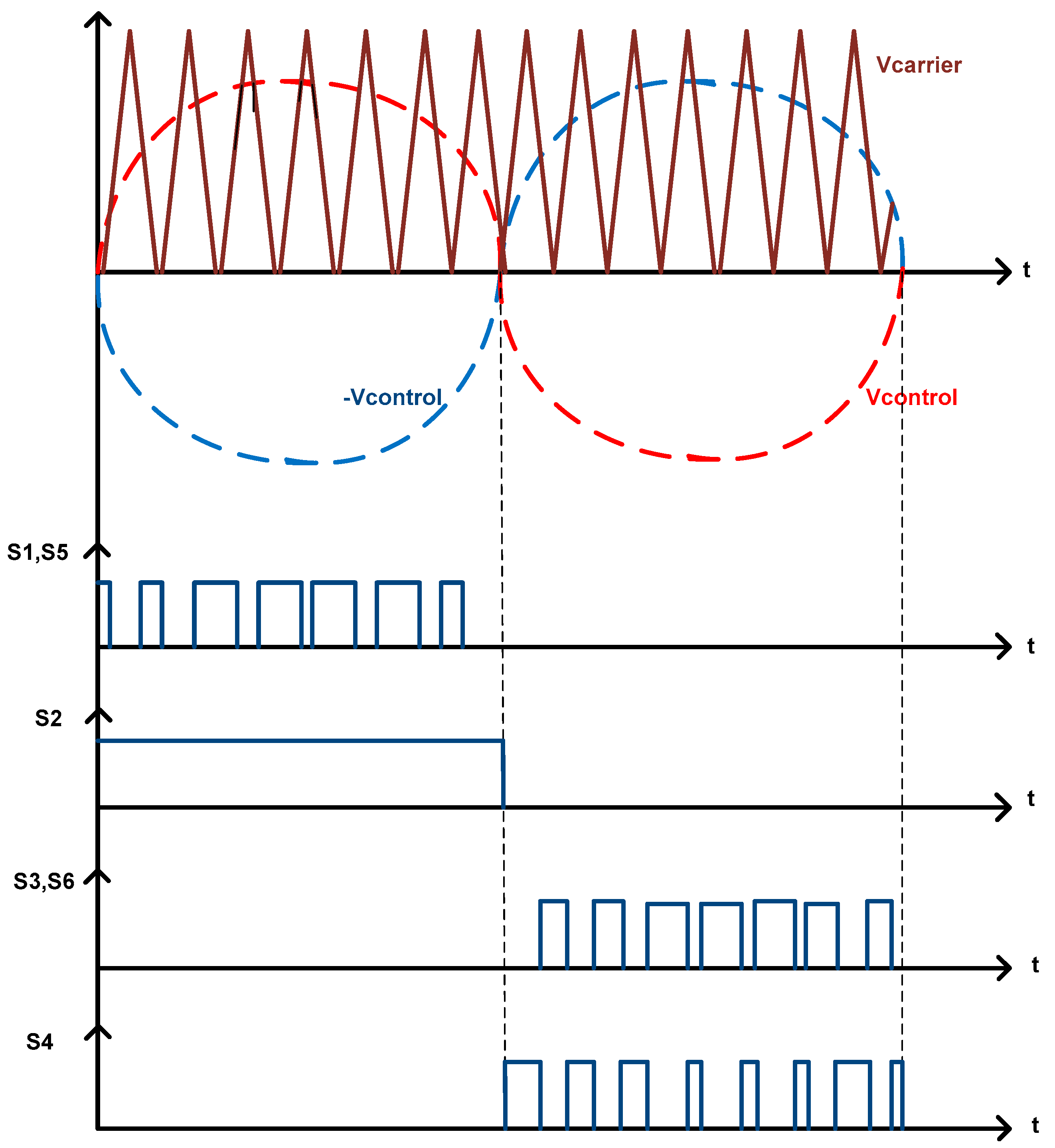
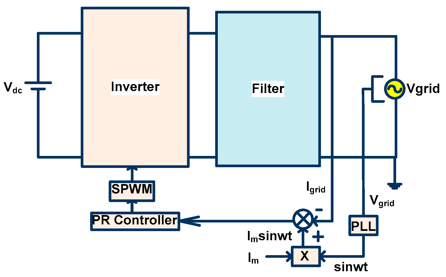
Control Strategy
6. Simulation Results and Discussion
6.1. H4 Simulation Output
6.2. H5 Inverter Simulation Output
6.3. H6 I Inverter Simulation Output

6.4. H6 II Inverter Simulation Output

6.5. H6 III Inverter Simulation Output

6.6. Proposed Novel H6 Inverter Simulation Output

7. Conclusions
Author Contributions
Funding
Institutional Review Board Statement
Informed Consent Statement
Data Availability Statement
Conflicts of Interest
Abbreviations
| Cpv | Parasitic capacitance between PV and ground |
| Vcm | Common mode voltage |
| Icm | Common mode current |
| A, B | Output terminals of inverter |
| P, N | Positive and negative terminals, respectively, of DC supply |
| VAN | Voltage between A and N |
| VBN | Voltage between B and N |
| Vdm | Differential mode voltage |
| Vpv | DC voltage generated by PV panel |
| L1, L2 | Filter inductors |
| Vg | Grid voltage |
| Nomenclature | |
| PV | Photovoltaics |
| HERIC | High efficiency and reliable inverter concept |
| SPWM | Sinusoidal pulse width modulation |
| HB-ZVR | H bridge zero-voltage state rectifier |
| BDC | Bidirectional clamping |
| SOGI-PLL | Second-order generalized integrator–phase lock loop |
| PR | Proportional resonant |
References
- Gupta, A.K.; Joshi, M.S.; Agarwal, V. Improved Transformerless Grid-Tied PV Inverter Effectively Operating at Twice the Switching Frequency with Constant CMV and Reactive Power Capability. IEEE J. Emerg. Sel. Top. Power Electron. 2019, 8, 3477–3486. [Google Scholar] [CrossRef]
- Khan, M.N.; Forouzesh, M.; Siwakoti, Y.P.; Li, L.; Kerekes, T.; Blaabjerg, F. Transformerless Inverter Topologies for Single-Phase Photovoltaic Systems: A Comparative Review. IEEE J. Emerg. Sel. Top. Power Electron. 2019, 8, 805–835. [Google Scholar] [CrossRef]
- Tan, F.; Suan, K.; Rahim, N.A.; Hew, W.P. Modeling, analysis and control of various types of transformerless grid connected PV inverters. In Proceedings of the 2011 IEEE First Conference on Clean Energy and Technology (CET 2011), Kuala Lumpur, Malaysia, 27–29 June 2011; pp. 51–56. [Google Scholar] [CrossRef]
- Mathi, A.A.D.; Ramaprabha, R. Comparative Analysis of Grid Connected Transformerless Photovoltaic Inverters for Leakage Current Minimization. Indian J. Sci. Technol. 2018, 11, 1–8. [Google Scholar] [CrossRef]
- Gonzalez, R.; Lopez, J.; Sanchis, P.; Marroyo, L. Transformerless Inverter for Single-Phase Photovoltaic Systems. IEEE Trans. Power Electron. 2007, 22, 693–697. [Google Scholar] [CrossRef]
- Araujo, S.V.; Zacharias, P.; Mallwitz, R. Highly Efficient Single-Phase Transformerless Inverters for Grid-Connected Photovoltaic Systems. IEEE Trans. Ind. Electron. 2010, 57, 3118–3128. [Google Scholar] [CrossRef]
- Kerekes, T.; Teodorescu, R.; Rodriguez, P.; Vazquez, G.; Aldabas, E. A New High-Efficiency Single-Phase Transformerless PV Inverter Topology. IEEE Trans. Ind. Electron. 2011, 58, 184–191. [Google Scholar] [CrossRef] [Green Version]
- Patrao, I.; Figueres, E.; Espin, F.G.; Garcera, G. Transformerless topologies for grid-connected single-phase photovoltaic inverters. Renew. Sustain. Energy Rev. 2011, 15, 3423–3431. [Google Scholar] [CrossRef] [Green Version]
- Hassaine, L.; OLias, E.; Quintero, J.; Salas, V. Overview of power inverter topologies and control structures for grid connectedphotovoltaic systems. Renew. Sustain. Energy Rev. 2014, 30, 796–807. [Google Scholar] [CrossRef]
- Li, W.; Gu, Y.; Luo, H.; Cui, W.; He, X.; Xia, C. Topology Review and Derivation Methodology of Single-Phase Transformerless Photovoltaic Inverters for Leakage Current Suppression. IEEE Trans. Ind. Electron. 2015, 62, 4537–4551. [Google Scholar] [CrossRef]
- Islam, M.; Mekhilef, S.; Hasan, M. Single phase transformerless inverter topologies for grid-tied photovoltaic system: A review. Renew. Sustain. Energy Rev. 2015, 45, 69–86. [Google Scholar] [CrossRef] [Green Version]
- Jana, J.; Saha, H.; Bhattacharya, K.D. A review of inverter topologies for single-phase grid-connected photovoltaic systems. Renew. Sustain. Energy Rev. 2017, 72, 1256–1270. [Google Scholar] [CrossRef]
- Ahmad, Z.; Singh, S.N. Comparative analysis of single phase transformerless inverter topologies for grid connected PV system. Sol. Energy 2017, 149, 245–271. [Google Scholar] [CrossRef]
- Zeb, K.; Uddin, W.; Khan, M.A.; Ali, Z.; Ali, M.U.; Christofides, N.; Kim, H.J. A comprehensive review on inverter topologies and control strategies for grid connected photovoltaic system. Renew. Sustain. Energy Rev. 2018, 94, 1120–1141. [Google Scholar] [CrossRef]
- Zhang, L.; Sun, K.; Feng, L.; Wu, H.; Xing, Y. A Family of Neutral Point Clamped Full-Bridge Topologies for Transformerless Photovoltaic Grid-Tied Inverters. IEEE Trans. Power Electron. 2013, 28, 730–739. [Google Scholar] [CrossRef]
- Ahmad, Z.; Singh, S.N. An improved single phase transformerless inverter topology for grid connected PV system with reduce leakage current and reactive power capability. Sol. Energy 2017, 157, 133–146. [Google Scholar] [CrossRef]
- Islam, M.; Mekhilef, S. H6-type transformerless single-phase inverter for grid-tied photovoltaic system. IET Power Electron. 2015, 8, 636–644. [Google Scholar] [CrossRef] [Green Version]
- Freddy, T.K.S.; Lee, J.-H.; Moon, H.-C.; Lee, K.-B.; Rahim, N.A. Modulation Technique for Single-Phase Transformerless Photovoltaic Inverters With Reactive Power Capability. IEEE Trans. Ind. Electron. 2017, 64, 6989–6999. [Google Scholar] [CrossRef]
- Albalawi, H.; Zaid, S.A. An H5 Transformerless Inverter for Grid Connected PV Systems with Improved Utilization Factor and a Simple Maximum Power Point Algorithm. Energies 2018, 11, 2912. [Google Scholar] [CrossRef] [Green Version]
- Anurag, A.; Deshmukh, N.; Maguluri, A.; Anand, S. Integrated DC–DC Converter Based Grid-Connected Transformerless Photovoltaic Inverter With Extended Input Voltage Range. IEEE Trans. Power Electron. 2018, 33, 8322–8330. [Google Scholar] [CrossRef]
- Kuncham, S.K.; Annamalai, K.; Nallamothu, S. A new structure of single-phase two-stage hybrid transformerless multilevel PV inverter. Int. J. Circ. Appl. 2018, 47, 152–174. [Google Scholar] [CrossRef] [Green Version]
- Li, H.; Zeng, Y.; Zhang, B.; Zheng, Q.; Hao, R.; Yang, Z. An Improved H5 Topology with Low Common Mode Current for Transformerless PV Grid Connected Inverter. IEEE Trans. Power Electron. 2018, 34, 1254–1256. [Google Scholar] [CrossRef]
- Siwakoti, Y.P.; Blaabjerg, F. Common-Ground-Type Transformerless Inverters for Single-Phase Solar Photovoltaic Systems. IEEE Trans. Ind. Electron. 2018, 65, 2100–2111. [Google Scholar] [CrossRef]
- Xu, M.; Zhang, L.; Xing, Y.; Feng, L. A Novel H6-Type Transformerless Inverter for Grid-Connected Photovoltaic Application. In Proceedings of the 7th IEEE Conference on Industrial Electronics and Applications (ICIEA 2012), Singapore, 18–20 July 2012; pp. 58–63. [Google Scholar] [CrossRef]
- Yang, B.; Li, W.; Gu, Y.; Cui, W.; He, X. Improved Transformerless Inverter with Common-Mode Leakage Current Elimination for a Photovoltaic Grid-Connected Power System. IEEE Trans. Power Electron. 2012, 27, 752–762. [Google Scholar] [CrossRef]
- Zhang, L.; Sun, K.; Xing, Y.; Xing, M. H6 Transformerless Full-Bridge PV Grid-tied Inverters. IEEE Trans. Power Electron. 2014, 29, 1229–1238. [Google Scholar] [CrossRef]
- Datta, A.; Bhattacharya, G.; Mukherjee, D.; Saha, H. Ground Leakage Current Elimination in a Transformerless Unipolar Modulation Based Single Phase Grid-Connected Photovoltaic System. In Proceedings of the IEEE PES Asia-Pacific Power and Energy Engineering Conference (APPEEC), Hong Kong, China, 8–11 December 2013. [Google Scholar] [CrossRef]
- Kumar, K.S.; Kirubakaran, A.; Subrahmanyam, N. Bidirectional Clamping-Based H5, HERIC, and H6 Transformerless Inverter Topologies With Reactive Power Capability. IEEE Trans. Ind. Appl. 2020, 56, 5119–5128. [Google Scholar] [CrossRef]
- Ahmad, S.; Mekhilef, S.; Mokhlis, H. A grid-tied photovoltaic transformer-less inverter with reduced leakage current. IOP Conf. Ser. Earth Environ. Sci. 2021, 673, 012016. [Google Scholar] [CrossRef]
- Gaafar, M.A.; Orabi, M.; Ibrahim, A.; Kennel, R.; Abdelrahem, M. Common-Ground Photovoltaic Inverters for Leakage Curent Mitigation: Comparative Review. Appl. Sci. 2021, 11, 11266. [Google Scholar] [CrossRef]


| Parameters | Values |
|---|---|
| Input Voltage | 400 V (DC) |
| Grid Voltage/Frequency | 230 V r.m.s/50 Hz |
| Grid Current | 7.07 A |
| DC bus Capacitor | 500 µF |
| Switching Frequency | 10 KHz |
| Filter inductors | L1 = L2 = 4.06 mH |
| PV parasitic capacitor | Cpv1 = Cpv2 = 1 nF |
| Ground Resistance | 5 Ω |
| A | B | C | D | E | F | G | H | ||
|---|---|---|---|---|---|---|---|---|---|
| Active Mode | Freewheeling Mode | Active Mode | Freewheeling Mode | ||||||
| H4 | 4 | 2 | - | 2 | - | Less | High | Less | Absent |
| H5 | 5 | 3 | 1 | 3 | 1 | More compared to H4, H 6 II, HERIC, novel H6 | Less compared to H4, H6 II, HERIC, novel H6 | Higher than H4 but less than H6 I, H6 II, H6 III, HERIC and novel H6 | DC side |
| H6 I | 6 | 3 | 1 | 3 | 1 | High compared to H4, H5, H6 II, HERIC, novel H6 | Less compared to H4, H5, H6 II, HERIC, novel H6 | High due to 6 switches | DC side |
| H6 II | 6 | 3 | 1 | 2 | 1 | Less compared to H5, H6 I, H6 III | High compared to H5, H6 I, H6 III | High due to 6 switches | DC side |
| H6 III | 6 | 4 | 1 | 4 | 1 | Maximum | Low | High due to 6 switches | DC side |
| HERIC | 6 | 2 | 1 | 2 | 1 | Least | Highest | High due to 6 switches | AC side |
| Novel H6 | 6 | 3 | 1 | 2 | 1 | Less compared to H5, H6 I, H6 III | High compared to H5, H6 I, H6 III | High due to 6 switches | DC side |
Publisher’s Note: MDPI stays neutral with regard to jurisdictional claims in published maps and institutional affiliations. |
© 2022 by the authors. Licensee MDPI, Basel, Switzerland. This article is an open access article distributed under the terms and conditions of the Creative Commons Attribution (CC BY) license (https://creativecommons.org/licenses/by/4.0/).
Share and Cite
Desai, A.A.; Mikkili, S.; Senjyu, T. Novel H6 Transformerless Inverter for Grid Connected Photovoltaic System to Reduce the Conduction Loss and Enhance Efficiency. Energies 2022, 15, 3789. https://0-doi-org.brum.beds.ac.uk/10.3390/en15103789
Desai AA, Mikkili S, Senjyu T. Novel H6 Transformerless Inverter for Grid Connected Photovoltaic System to Reduce the Conduction Loss and Enhance Efficiency. Energies. 2022; 15(10):3789. https://0-doi-org.brum.beds.ac.uk/10.3390/en15103789
Chicago/Turabian StyleDesai, Aditi Atul, Suresh Mikkili, and Tomonobu Senjyu. 2022. "Novel H6 Transformerless Inverter for Grid Connected Photovoltaic System to Reduce the Conduction Loss and Enhance Efficiency" Energies 15, no. 10: 3789. https://0-doi-org.brum.beds.ac.uk/10.3390/en15103789