
System-Based Testing of Protection for Center-Tapped Shunt Capacitor Banks


Department of Electrical, Electronics and Computer Engineering, Center for Substation, Automation and Energy Management Systems, Cape Peninsula University of Technology, Bellville Campus, Cape Town 7535, South Africa
*
Author to whom correspondence should be addressed.
Energies 2022, 15(10), 3791; https://0-doi-org.brum.beds.ac.uk/10.3390/en15103791
Submission received: 8 March 2022
/
Revised: 25 April 2022
/
Accepted: 10 May 2022
/
Published: 21 May 2022
Abstract
:In power systems, capacitor banks play a significant role in improving voltage profiles, reducing losses, and adjusting power factors. Security measures must be implemented quickly and reliably to protect them from a wide range of threats. As a consequence of capacitor bank failures, finding and fixing the damaged units/elements is more difficult, which may lead to voltage control difficulties or the loss of any of these benefits. The paper shows the application of system-based testing methods for protection systems using RelaySimTest software, which works with OMICRON injection test sets. System-based testing methods are applied to test voltage differential protection for center-tapped shunt capacitor banks. The use of system-based testing methods has many advantages over conventional testing methods, which include distributed testing, transient state conditions testing, etc., which in turn result in cost savings during the commissioning and testing phase. The impact of external faults on bank installation has been tested successfully.
1. Introduction
Capacitor banks are built from tiny capacitor elements and cans that are linked in series and parallel to create groupings known as capacitor units. These capacitor units are then connected in series and parallel to create the necessary capacitor bank size in terms of voltage and reactive power ratings. The industrial applications include several capacitor bank connections such as delta, grounded wye, ungrounded wye, grounded double wye, and so on. The capacitor bank design configuration includes externally fused, internally fused, fuseless, and unfused capacitor banks. Sensitive and reliable protection is necessary to identify even a single capacitor element failure without ambiguity. For this aim, a voltage differential protection technique is used, which is applied to a grounded wye-connected fuseless shunt capacitor bank. The paper aims to demonstrate how system-based testing methods can be applied to testing the protection of center-tapped shunt capacitor banks, particularly voltage differential protection. System-based methods provide advantages such as distributed testing, transient state conditions testing, etc., which results in cost savings during the commissioning phase.
A current and voltage imbalance protection method, as well as its strengths and weaknesses, as well as an impedance-based protection scheme, were demonstrated in [1]. A unique approach for computing imbalance currents observed due to fuseless capacitor unit/element failures is provided [2], with two operation modes of alert and trip. Ref. [3] proposed a novel approach to protecting the capacitor banks that modifies the impedance relay scheme to achieve the capacitor bank protection function with reliability. Ref. [4] is the IEEE guide for protecting shunt capacitor banks. It lists the minimum requirements that must be met for the bank to be safe. Protective relay settings for both grounded and ungrounded shunt capacitor banks are explained in [5]. This includes phase overcurrent, negative overcurrent, and overvoltage, as well as how to set them. Ref. [6] discusses the application, speed, and sensitivity of protection techniques used on C-type filter banks, capacitively grounded, double H banks. Ref. [7] discusses the application guide for protecting fuseless shunt capacitor banks using SEL 487 V relays. A traveling wave (TW) shunt capacitor bank protection approach is provided [8]. Ref. [9] discusses the superimposed current and differential voltage protection and fault identification approach. Ref. [10] describes using a boundary area-based algorithm to protect shunt capacitor banks [11]. To keep the shunt capacitor bank safe, there is a voltage differential protection technique and a system-based testing method done with a SEL487 V relay, RelaySimTest software, and IEC 61508 GOOSE communications. The paper introduced system-based testing methods on grounded, fuseless shunt capacitor banks earthed via a low voltage capacitor. This phenomenon does not demonstrate the individual element failures below the tap position, as there’s only one capacitor unit which, when it fails, results in 0 V measured at the tap position. This paper seeks to address this phenomenon by applying a system-based method on center-tapped shunt capacitor banks to demonstrate the impact individual element failures have below the tap, similarly to what happens above the tap. An improvement in the simulation of element failures has been automated for testing.
A system-based protection system testing approach based on RelaySimTest software, which allows for remote and time-synchronized measurements, is described, along with an application example [12]. Ref. [13] describes using a system-based testing method for distance protection of a transformer used as backup protection. Communication-based distribution automation systems for transient system condition testing are presented [14]. Implementing transformer differential protection using RelaySimTest software’s system-based testing approach is being explored [15]. The RelaySimTest system-based testing approach for determining ground fault is described [16]. System-based testing methods can test both steady-state and transient-state situations and dispersed testing, which saves money when the system is being built.
This paper’s research contribution shows the application of a system-based testing approach for voltage differential protection schemes for center-tapped shunt capacitor banks using Omicron RelaySimTest software and the SEL487V IED and also provides improvements to work done by [11]. The paper also identifies a shortfall of voltage differential protection for the balanced type of element failures and how to deal with this phenomenon using backup overcurrent protection. The possibility of software simulating the realistic power system events allows validation of the correct operation of the entire protection system, which reveals settings, logic, and any design errors that may exist. With the simulation of the entire electrical network, the impact of the external faults on the capacitor bank is tested, as well as the impact of the failure of the capacitor bank on the entire protection system of the electrical network. One of the benefits of using system-based testing methods is the distributed testing possibility, which allows testing of protection systems in separate locations at the same time on one computer. This provides cost savings due to reduced commissioning time. It costs about ZAR 130,000 to use System-based testing software, which uses tools like OMICRON injection test sets, GPS clocks, network switches, and so on. To that end, the IEC61850 standard-based GOOSE and MMS communication protocols were set up to help utilities find problems in the bank as soon as possible and plan outages to fix them before they cause a catastrophic problem.
The paper is divided into five sections. Section 1 begins with an introduction that includes a brief literature review on shunt capacitor bank protection and system-based testing methods for protection systems. Section 2 describes the system under study, system simulation, protection settings calculations, and lab-scale implementation. Section 3 provides test result discussion and analysis. Section 4 provides paper discussions, while Section 5 provides paper conclusions.
2. Materials and Methods
2.1. Power System Network Modelling and Simulation with Capacitor Banks
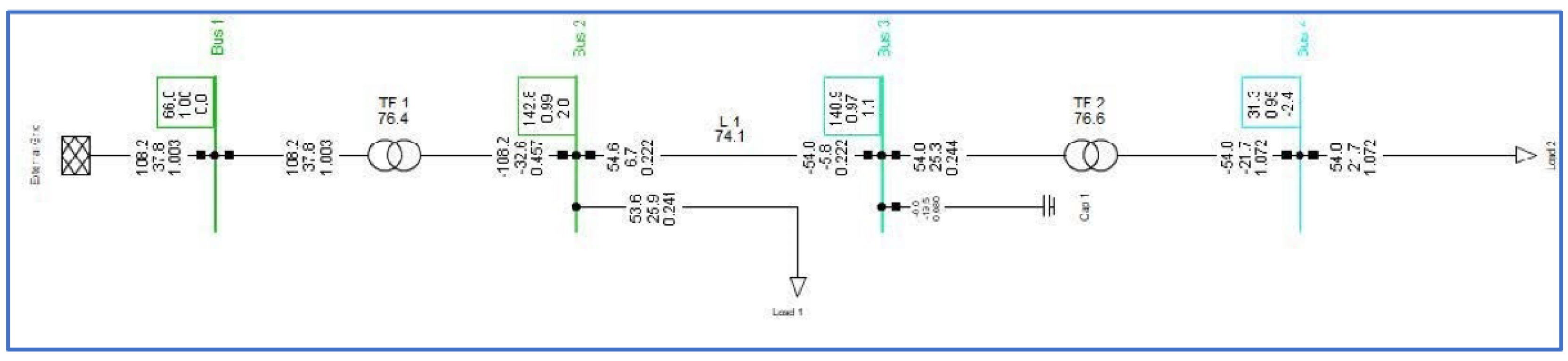
Table 1 depicts the data of the power system network simulated on RelaySimTest software as shown in Figure 1, including the installation of a 22 Mvar capacitor bank rated at 149.65 kV in Bus 3. Bus 1 is connected to the external grid at 66 kV, and the voltage measured is 1 p.u. Bus 2 has a voltage of 0.99 p.u., Line 1 has a loading of 74.1 percent, Bus 3 has a voltage of 0.97 p.u., Transformer 2 has a loading of 76.6 percent, and Bus 4 has a voltage of 0.95 percent. In this case, when the capacitor bank isn’t in the network, voltages on both Bus 3 and Bus 4 fall below the 5% regulation. This means the availability of the capacitor bank in the network must be as close to 100% as possible. The protection mechanism outlined in the study is meant to make sure that the capacitor bank is providing voltage regulation and reactive power compensation.
2.2. Calculation for Capacitor Bank Configuration and Voltage Differential Settings
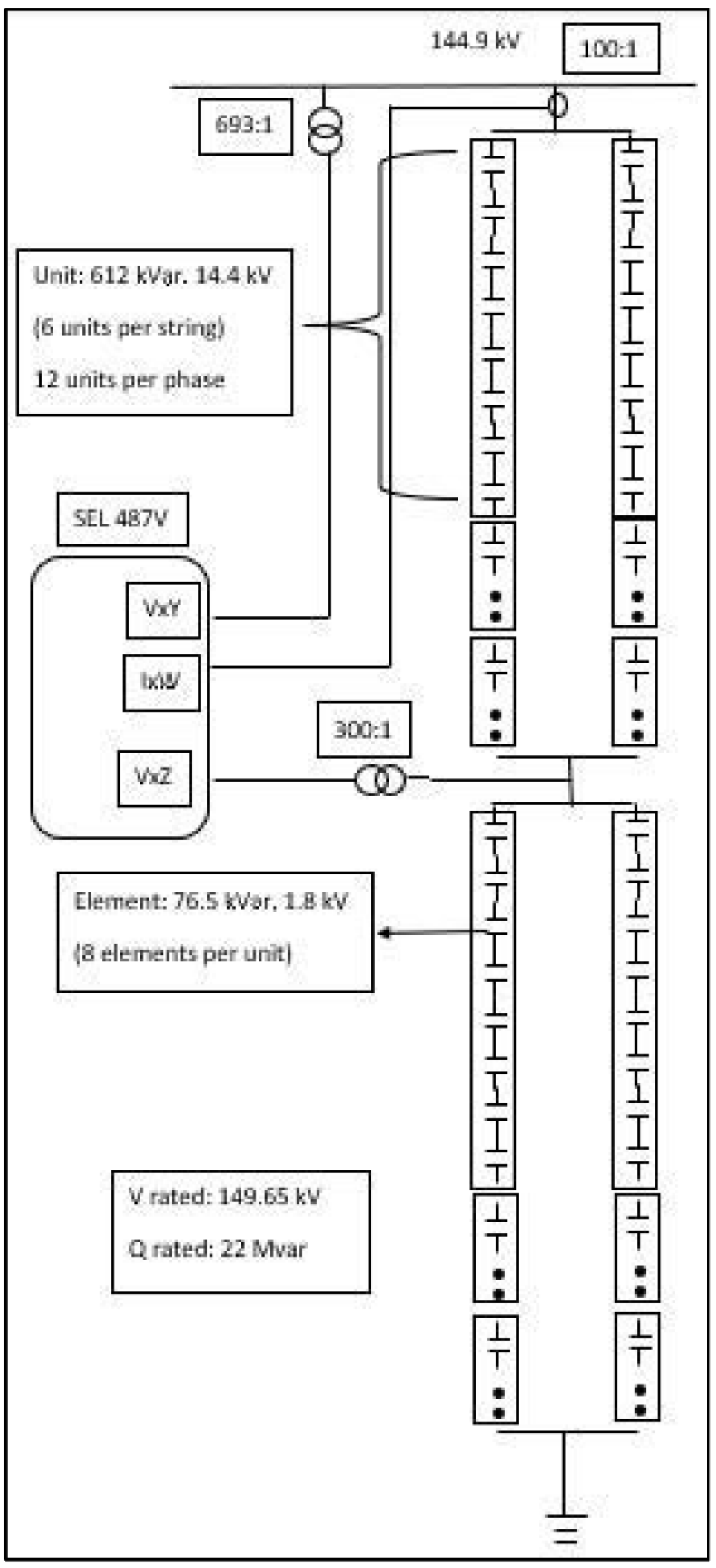
Figure 2 depicts the schematic of a 22 Mvar capacitor bank that has been installed. The capacitor bank contains two parallel strings per phase, six series capacitor units of 612 kvar each rated at 14.4 kV, and eight elements of 76.5 kvar each rated at 1.8 kV. The capacitor bank is center-tapped, as shown in Figure 3, which divides the bank into two parts. A voltage differential is calculated by comparing the center-tapped voltage to the bus voltage, and the voltage transformer ratios are 693:1 for the bus and 300:1 for the tap.
Considering that the voltage and reactive power ratings of each element are known, the impedances can be calculated using the following formulas below.
Element equivalent impedance
Rated element voltage
Rated element power
The total impedance calculation for the parallel strings above and below tap produces the following results per phase.
The total impedance for the capacitor bank per phase is shown in the following.
The current flowing through the capacitor bank during normal operation is shown below.
Rated bus voltage (phase)
Capacitor current
The secondary voltages for bus and capacitor tap positions are shown in Equations (5) and (6) below.
Secondary voltage of bus VT
Secondary voltage of tap VT
The following formula is used to calculate the differential voltage: comparing secondary bus voltage to secondary tap voltage, applying the “k” factor to compensate for any intolerances, and ensuring that the differential voltage equates to zero, “0” during normal operating conditions.
The k factor is calculated as shown below, and the normal operating conditions are shown in Equation (7c).
Table 2 shows the number of capacitor element failures and their impact on the differential voltage measured by the relay for both above-tapped failures. A similar calculation for element failures below the tap results in an equal differential voltage but opposite signs. An alert is produced for a failure of three elements; a failure of four elements trips the breaker, and a failure of more than four elements triggers a high-set element trip for the breaker.
A simultaneous failure of an equal number of capacitor elements on both halves results in a differential voltage of “0”, while voltage stress on healthy capacitor elements increases and is not detected by the voltage differential protection, and backup protection is triggered. When six elements above and six elements below the tap fail, the voltage stress on the healthy components exceeds 110 percent, and the calculated current exceeds 96 A. As a result, a backup overcurrent protection is set off at 96 A, which disconnects the bank from the network to protect it.
2.3. Shunt Capacitor Bank Protection Implementation on a Lab Scale
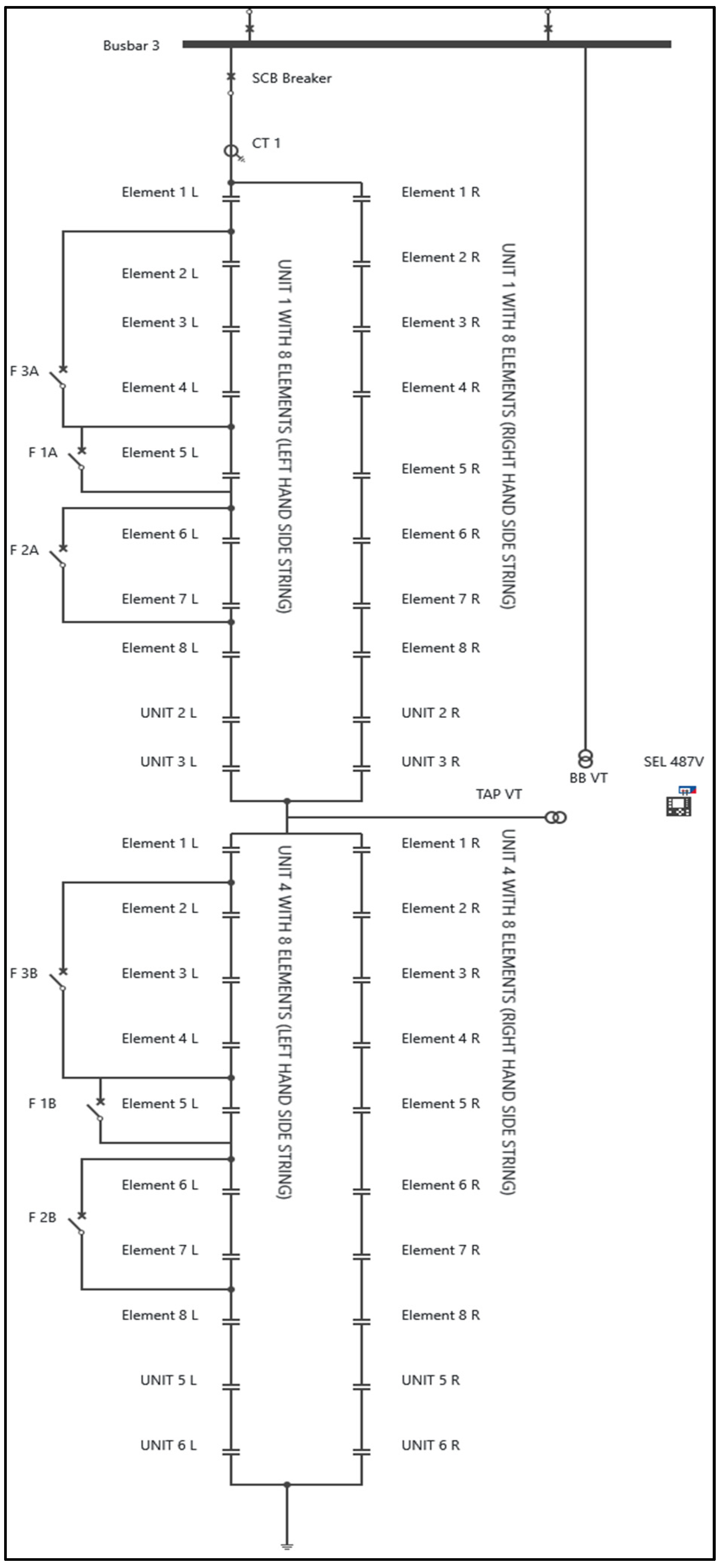
As illustrated in Figure 3, a lab-scale test bench is built to enable testing opportunities for voltage differential protection schemes for center-tapped shunt capacitor banks employing system-based testing methods. The power system network shown in Figure 1 is simulated on the engineering PC using RelaySimTest software. This simulation considers both steady-state and transient power system circumstances. There are two CMC test sets that are linked to the RelaySimTest software-simulated instrument transformers (VTs and CTs) for injection of those measurements into the SEL 487 V protection relay. SEL AcSELerator Architect, OMICRON’s Test Universe, SEL SynchroWave Event, SEL AcSELerator Diagram Builder, OMICRON’s IED Scout, and SEL SynchroWave Event are used to set up and test the system simulation.
3. Simulation Results and Analysis
Simulation results and outcomes are analyzed in this section of the paper for three case studies: (1) Four capacitor element failures above the tap, (2) Five capacitor element failures below the tap, and (3) Six capacitor element failures above the tap and six capacitor element failures below the tap.
3.1. Simulation Results for Four Element Failures Below Tap
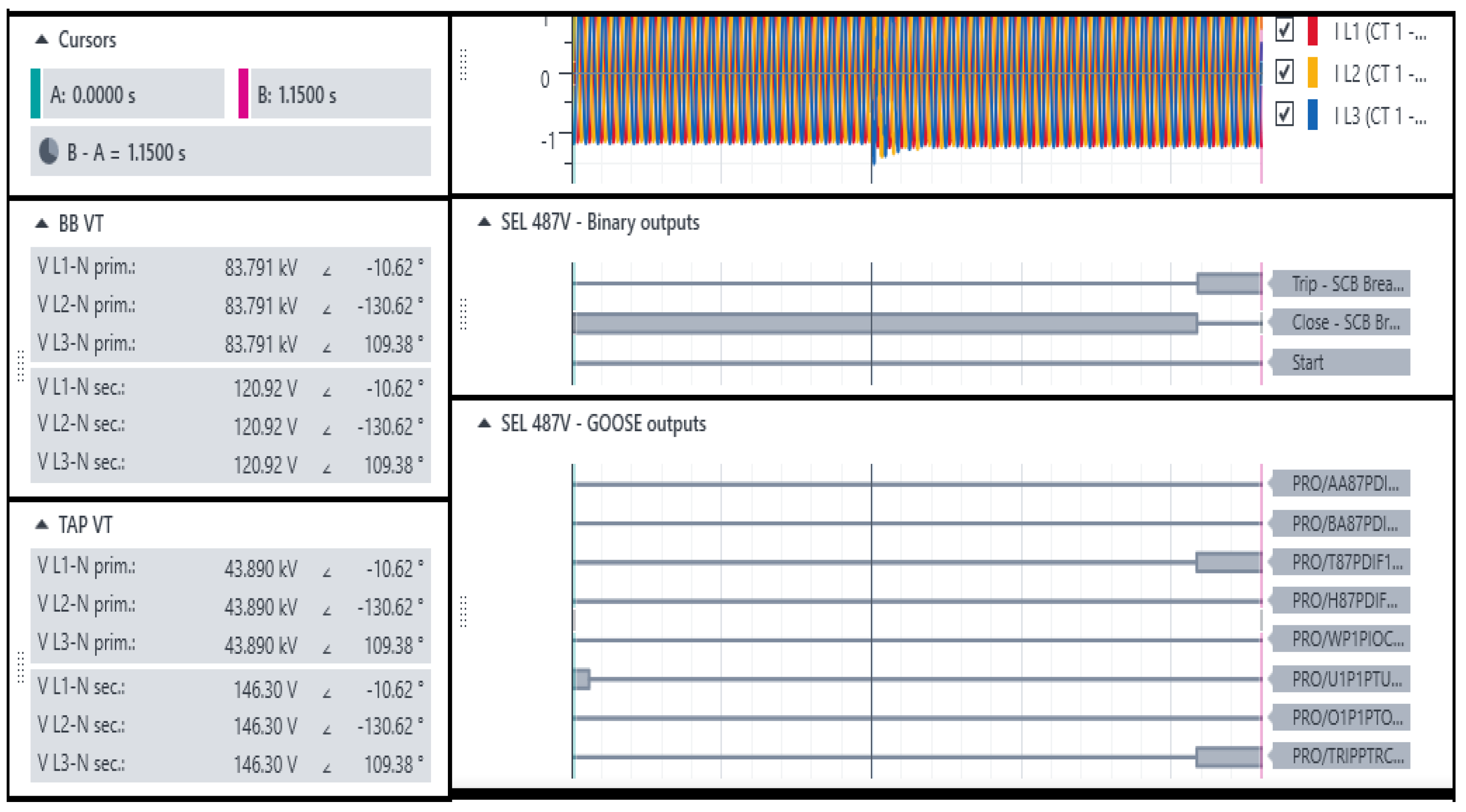
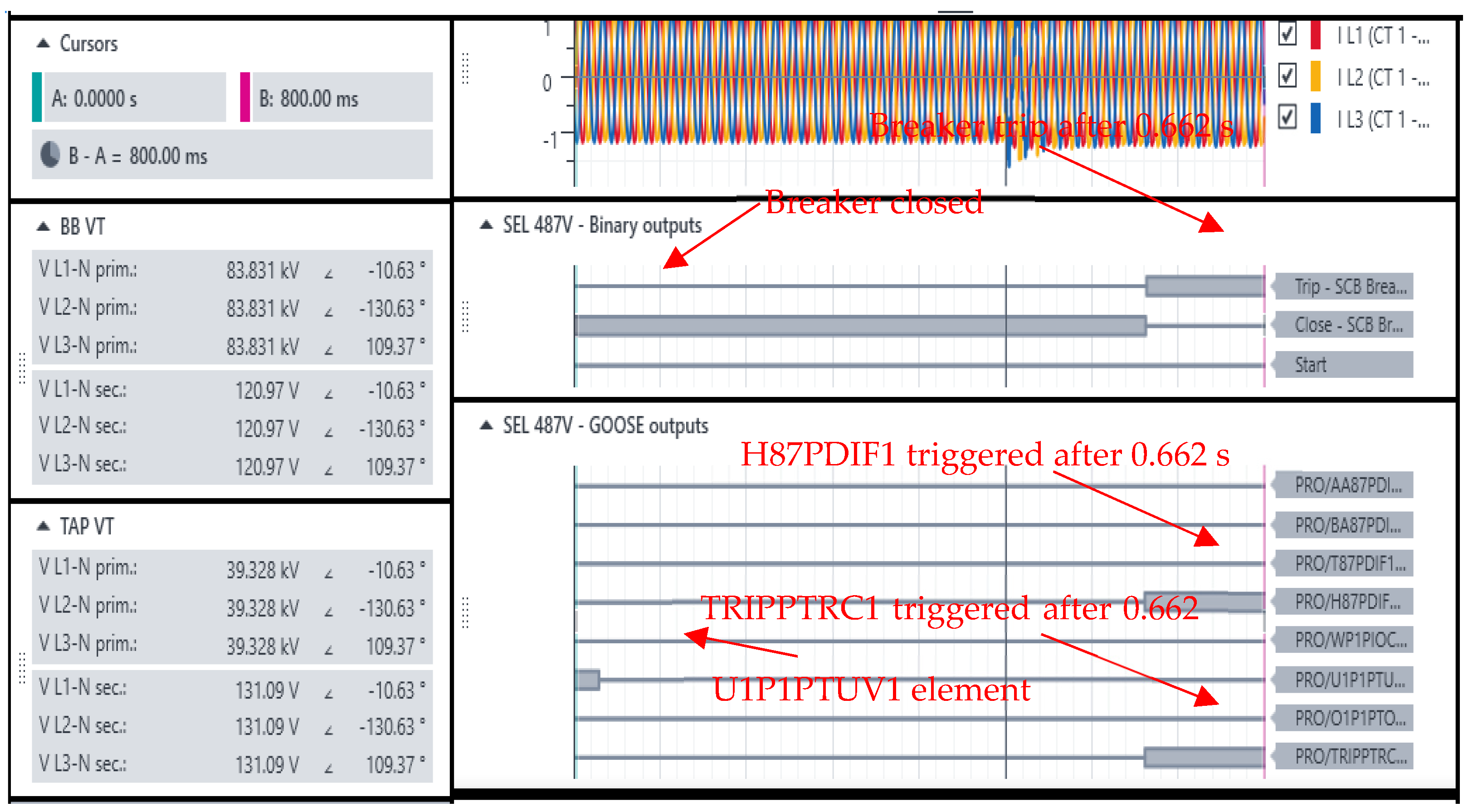
The results for four-element failures below tap are presented in Figure 4 and Figure 5, and a trip signal is issued at about 542 milliseconds after fault inception with both T87PDIF1 and TRIPPTRC1 logical nodes set high. The TRIPPTRC1 logical node is a conditional trip that is triggered by any trip condition. A BB voltage of 120.92 V is recorded, while a tap voltage of 146.30 V is detected, which results in a differential voltage of 5.78 V. Table 3 shows a summary of the voltage measurements detected by the relay.
3.2. Simulation Results for Five Element Failures above Tap
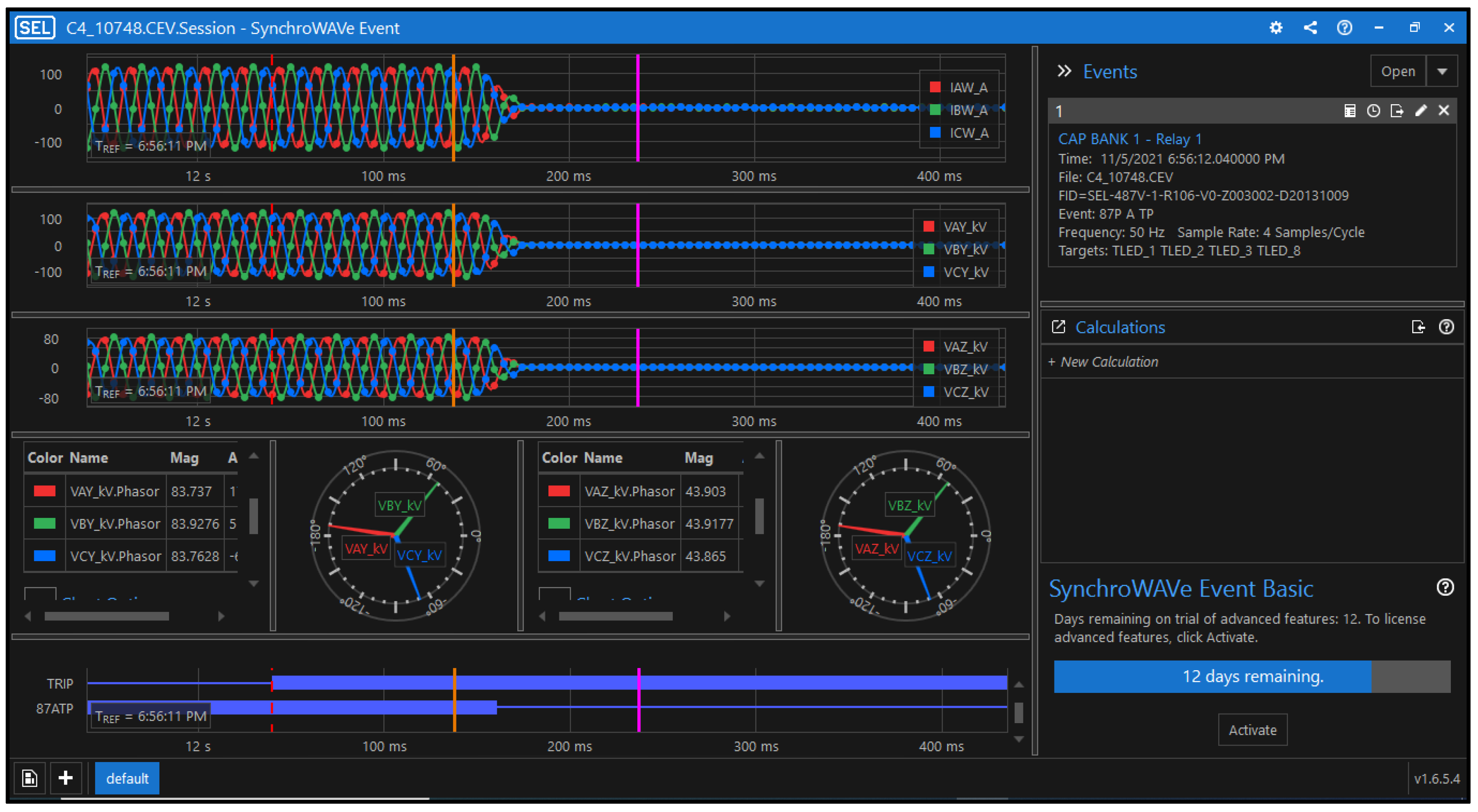
Five-element failures above tap simulation results are presented in Figure 6 and Figure 7, which trigger high set tripping settings. A trip signal is received from the relay at about 162 milliseconds from the fault inception due to a voltage differential threshold exceedance of 6.5 V and a delay of 120 ms. The 40 ms difference is due to relay trip time as well as communication and processing delays. Table 4 shows the summary of results for five element failures, which result in a high-set function being triggered. As shown in Figure 7, an undervoltage is also triggered.
3.3. Simulation Results for a Simultaneous Failure of Six Elements above and below the Tap
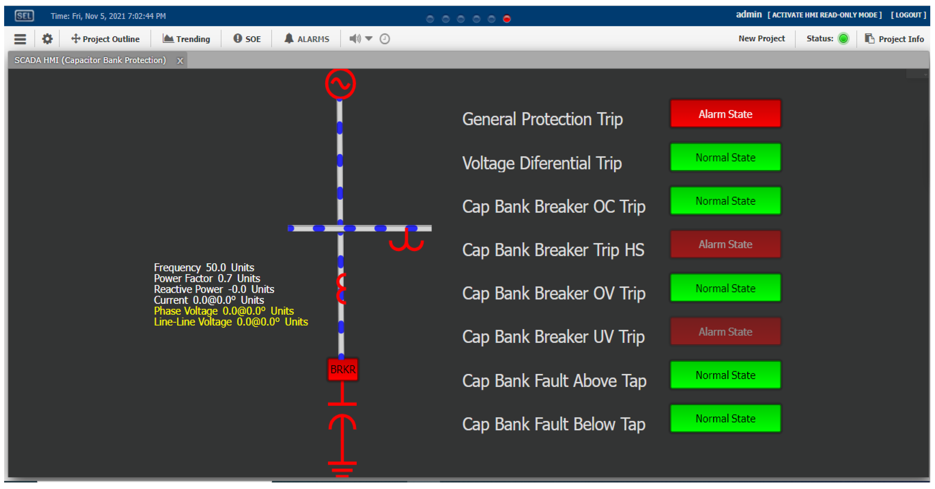
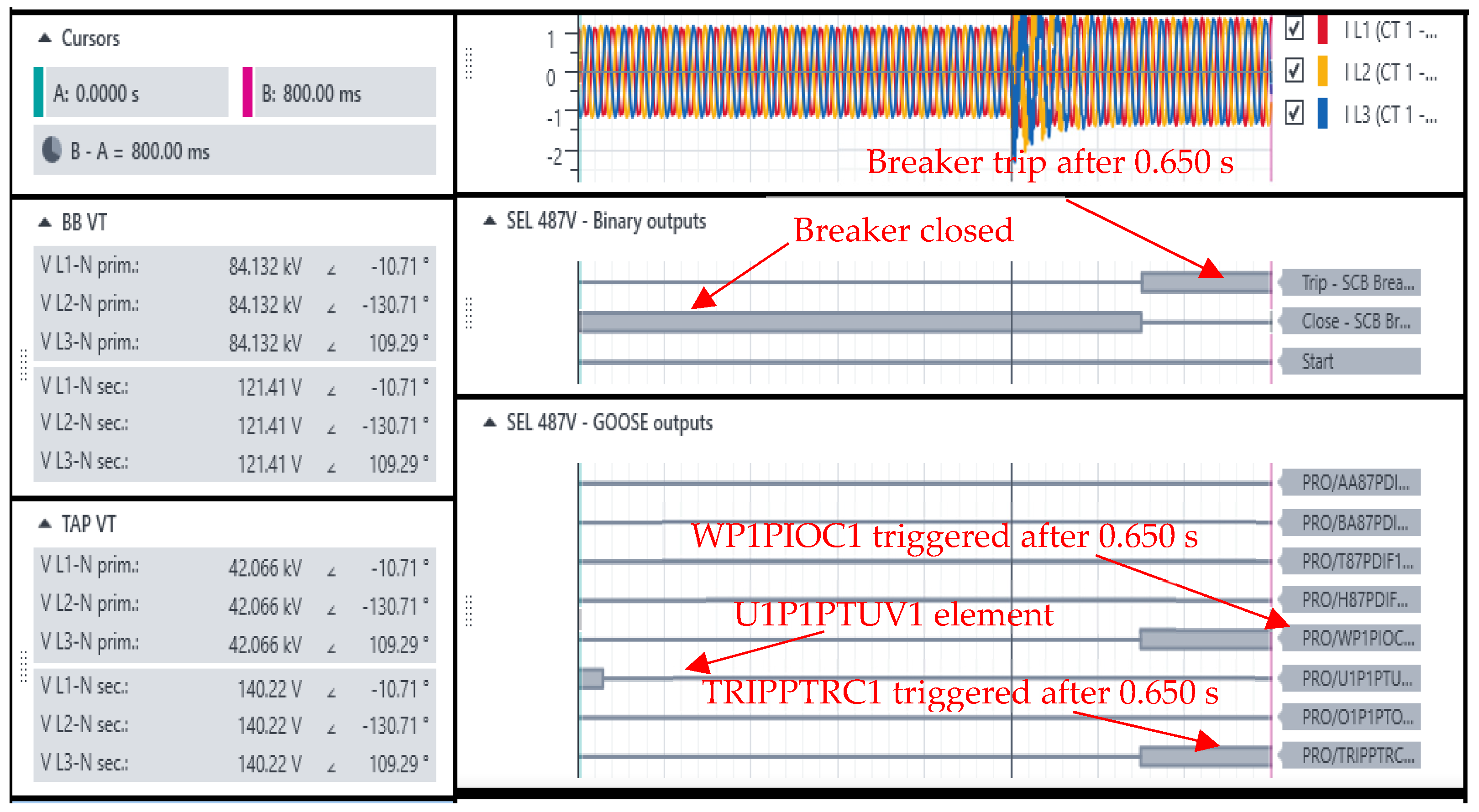
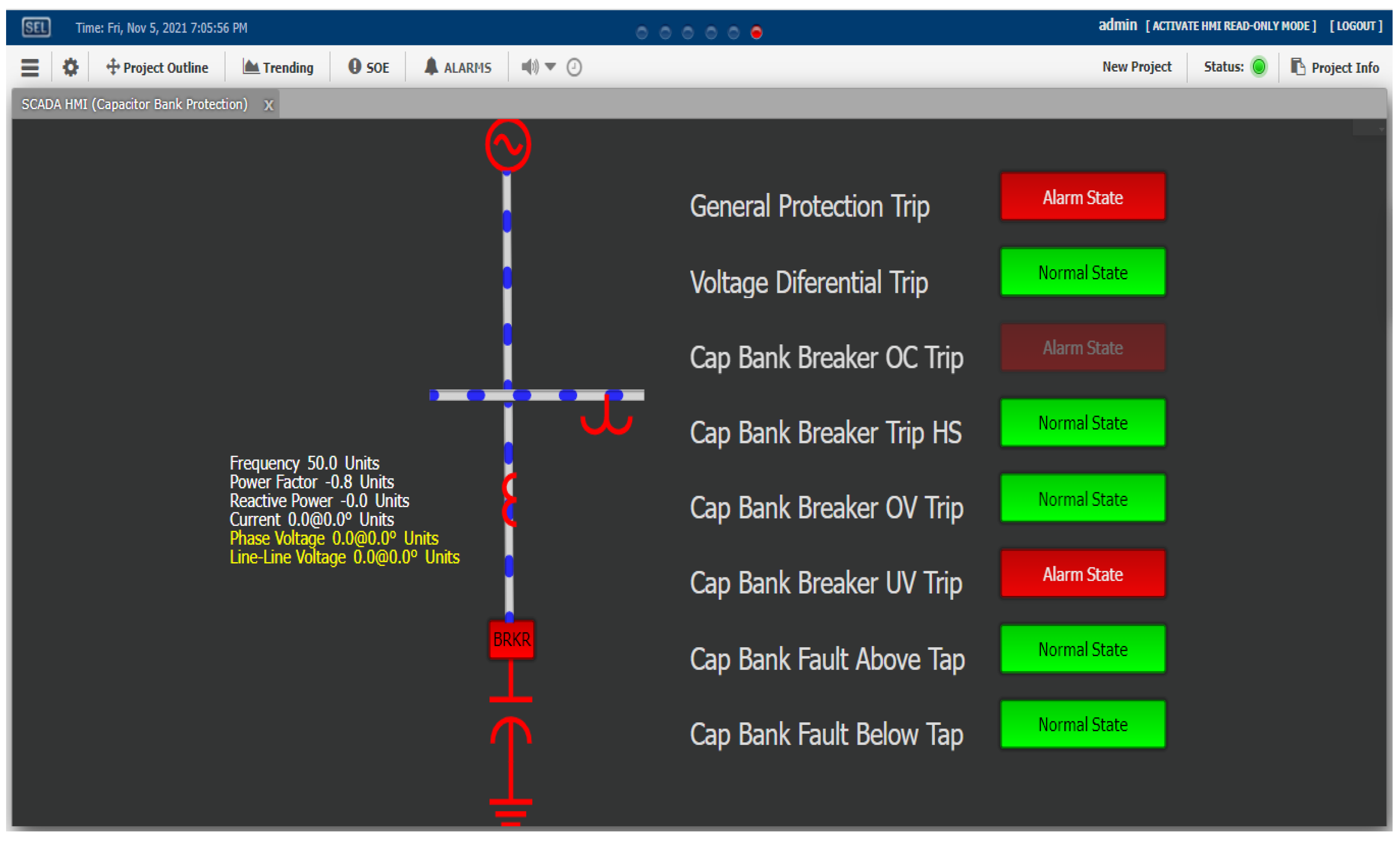
A simultaneous failure of six capacitor elements above and below the tap results in a differential voltage of 0 V. The phenomenon is not detected by the main protection voltage differential, and the overcurrent backup protection is triggered as the current flowing through the capacitor bank is above the pickup value of 96 A with voltage stress on healthy elements above 110% of their nominal value. As shown in Figure 8, the BB voltage is 121.41 V while the tap voltage is 140.22 V, resulting in a differential voltage of 0.021 V. As shown in Table 5, the scenario presents an overvoltage of 110% on the remaining healthy elements, and as such, the capacitor bank breaker tripped to avoid further damage. Figure 9 shows the HMI representation with the overcurrent trip indication depicted in red text. Undervoltage element trip is also shown as red text, caused by the stopping the voltage injection into the protection relay.
Table 6 summarizes the test findings reported in the various test cases described previously. As demonstrated in Table 6, the installed protection system functioned according to the design expectations of protective settings. When four elements fail, the breaker trips after 500 ms. When five elements fail, the breaker trips 120 ms later, with backup overcurrent protection coming into play. When six elements above and below the tap fail simultaneously, both the breaker and the backup overcurrent protection trip.
4. Discussion
Capacitor banks play a crucial part in power system networks, and their availability after installation should be practically ensured when needed. The critical components of the network ensure voltage profile improvement, loss minimization, power factor correction, and so on. Using different scenarios to calculate the settings reveals that two possibilities are rare and highly unlikely to occur. The first is the failure of capacitor components on parallel strings in the same part of the bank. As the differential voltage varies in small steps, more elements must fail before being picked up than in the regular scenario. It is also possible that both bank halves of the capacitors fail at the same time, resulting in no difference in voltage. This is the second thing that could happen, as more capacitor element failures were simulated, the voltage computed on the remaining healthy capacitor elements exceeded 110 percent, up to six-element failures above and six-element failures below the tap. This scenario requires the adoption of backup protection with the aid of DMT. Overcurrent protection is utilized. According to the computation, the threshold for stage 1 is 96 A, which is linked to 6 element failures above and 6 element failures below the tap.
The values for stages 2 and 3 were calculated to be 108 A and 324 A, respectively. Another type of backup protection method is the over/under voltage scheme, which is utilized as system protection for defects that occur outside of the bank installation. This protection technique was mostly useful for non-ground failures because there were no zero sequence components to flow through the capacitor bank to the ground. Using system-based testing methodologies, a lab-sized test bench is used to confirm the correct operation and effectiveness of the voltage differential protection scheme as described above. The test bench required the configuration of relay software and hardware setup. The research outcome intends to use a distributed type of protection testing using the RelaySimTest application suite. System-based testing methods can be used to test both steady-state and transient-state situations and can be distributed through time-synchronized test sets, which can save money during the commissioning phase.
5. Conclusions
Shunting Capacitor Banks are important components of a power system since they provide several benefits, such as power factor correction, loss reduction, and voltage profile improvement. As a result, they require swift and dependable protection against faults that are either internal or external to the bank installation. Voltage differential protection provides adequate protection for center-tapped capacitor banks, but backup protection is required for failures that occur outside the bank installation and those that are not detected by the main protection. The protection method selected requires advanced testing methods to eliminate any settings, logic, and design errors that may exist that would lead to incorrect operation or capacitor bank damage.
The system-based testing method provides a remote testing facility, for example, a test engineer and a protection relay at two different geographical locations. There is no need for the test engineer to travel to the site. If communication is established, then remote protection testing is feasible. In this paper, the authors utilized a system-based testing method to test the voltage differential protection for center-tapped shunt capacitor banks. The distributed remote testing provides cost savings during the substation commissioning phase, as well as the possibility of testing both steady-state conditions and transient conditions. System-based testing utilizes existing tools such as OMICRON injection test sets, GPS clocks, etc., besides the software (RelaySimTest), which costs about ZAR 130 000 per injection device. The testing quality is improved as advanced relay functions such as power swings, transient ground faults, etc., can be tested. Distributed testing is possible by controlling multiple CMC injection units from a single computer connected via the internet.
Author Contributions
Conceptualization, M.A.M. and S.K.; methodology, M.A.M. and S.K.; software, M.A.M.; validation, M.A.M. and S.K.; formal analysis, M.A.M.; investigation, M.A.M.; resources, S.K.; data curation, M.A.M. and S.K.; writing—original draft preparation, M.A.M.; writing—review and editing, M.A.M. and S.K.; visualization, M.A.M.; supervision, S.K.; project administration, S.K.; funding acquisition, S.K. All authors have read and agreed to the published version of the manuscript.
Funding
This research was funded by NRF Thuthuka Grant number 138177 and The APC was funded by NRF, ESKOM and CPUT.
Institutional Review Board Statement
Not applicable.
Informed Consent Statement
Not applicable.
Data Availability Statement
Not applicable.
Conflicts of Interest
The authors declare no conflict of interest.
References
- Bishop, M.; Day, T.; Chaudhary, A. A primer on capacitor bank protection. IEEE Trans. Ind. Appl. 2001, 37, 1174–1179. [Google Scholar] [CrossRef]
- Horton, R.; Warren, T.; Fender, K.; Harry, S.; Gross, C. Unbalance protection of fuseless, split-wye, grounded, shunt capacitor banks. IEEE Trans. Power Deliv. 2002, 17, 698–701. [Google Scholar] [CrossRef]
- Lee, W.-J.; Narayanan, K.; Maffetone, T.; Didsayabutra, P. The design of a capacitor bank early warning system. IEEE Trans. Ind. Appl. 2003, 39, 306–312. [Google Scholar] [CrossRef]
- C37.99-2012; IEEE Guide for the Protection of Shunt Capacitor Banks IEEE Standard C37.99-2012 (Revision of IEEE Standard C37.99-2000). System, P.; Committee, R.; Power, I.; Society, E. (Eds.) IEEE: Piscataway, NJ, USA, 2013. [Google Scholar] [CrossRef]
- Smith, T. Determining settings for capacitor bank protection. In Proceedings of the 2010 63rd Annual Conference for Protective Relay Engineers, College Station, TX, USA, 29 March–1 April 2010. [Google Scholar] [CrossRef]
- Moxley, R.; Pope, J.; Allen, J. Capacitor bank protection for simple and complex configurations. In Proceedings of the 2012 Annual Conference for Protective Relay Engineers, College Station, TX, USA, 2–5 April 2012; pp. 436–441. [Google Scholar] [CrossRef]
- Amberg, A.; Young, J. Protecting a Grounded Fuseless Capacitor Bank with the SEL-487V; Application Guide: Pullman, WA, USA, 2010; pp. 1–20. [Google Scholar]
- Jena, S.; Mohanty, R.; Pradhan, A.K. A Traveling Wave-Based Method for Protection of Shunt Capacitor Banks. IEEE Trans. Power Deliv. 2021, 1, 1–11. [Google Scholar] [CrossRef]
- Mohanty, R.; Pradhan, A.K. Time-Domain Protection and Fault Location of Wye-Connected Shunt Capacitor Banks Using Superimposed Current and Differential Voltage. IEEE Trans. Power Deliv. 2020, 36, 3486–3495. [Google Scholar] [CrossRef]
- Lertwanitrot, P.; Ngaopitakkul, A. Application of Magnitude and Phase Angle to Boundary Area-Based Algorithm for Unbalance Relay Protection Scheme in 115-kV Capacitor Bank. IEEE Access 2021, 9, 35709–35717. [Google Scholar] [CrossRef]
- Senthil, K.; Jones, R.; Mquqwana, M.A. System-based testing of a voltage differential protection scheme for shunt capacitor bank. In Proceedings of the 2020 7th International Conference on Power and Energy Systems Engineering, Fukuoka, Japan, 26–29 September 2020. [Google Scholar]
- Skrbinjek, O.; Cialla, B. Simulation-Based Testing and Measurements—Experiences. OMICRON is an acronym for the International Protection Testing Symposium. 2015.
- Garcia, A.; Baumeister, J. System-based Testing of Distance for Protection Transformer Backup, Application Note for OMICRON. 2017.
- Geiger, S.; Pritchard, C. Transient testing of communication based distribution automation schemes. In Proceedings of the IET International Conference on Resilience of Transmission and Distribution Networks (RTDN 2017), Birmingham, UK, 26–28 September 2017; pp. 1–4. [Google Scholar] [CrossRef]
- Fink, F. System-based Testing of Transformer Differential Protection, Application Note for OMICRON. 2017.
- Fink, F. System-based Testing of Ground Fault Determination. Application Note for OMICRON. 2019.
Figure 1.
Load Flow Results of the network.

Figure 2.
A power system with a capacitor bank configuration is being investigated.

Figure 3.
RelaySimTest was used to create a Capacitor Bank Model.

Figure 4.
RelaySimTest simulation results for four-element failures below the tap.

Figure 5.
SynchoWAVE Event simulation results for four-element failures below the tap.

Figure 6.
Simulation results for five elements failure below the tap.

Figure 7.
Human Machine Interface for five element failures below the tap.

Figure 8.
RelaySimTest simulation results for a simultaneous failure of six element failures above and below the tap.
Figure 8.
RelaySimTest simulation results for a simultaneous failure of six element failures above and below the tap.

Figure 9.
A human-machine interface for a simultaneous failure of six element failures above and below the tap.
Figure 9.
A human-machine interface for a simultaneous failure of six element failures above and below the tap.


Table 1.
Network Data.
| External Grid | Line | Transformer 2 | |||
|---|---|---|---|---|---|
| Bus Type | Slack Bus | Rated Voltage | 144.9 kV | Type | 2 winding |
| Angle | 0 | Rated Current | 1 kA | Rating | 80 MVA |
| Voltage | 1 pu | AC Resistance (1, 2) | 0.2376 Ω/km | Voltage | 144.9/33 kV |
| Short circuit VDE/IEC | 1000 MVA max | Reactance (1, 2) | 0.3465 Ω/km | Impedance | 7.5 % |
| 800 MVA min | AC Resistance (0) | 0.2546 Ω/km | Copper Losses | 5.5 kW | |
| Reactance (0) | 0.3245 Ω/km | Vector group | YN/YN | ||
| Transformer 1 | Length | 18.56 km | |||
| Type | 2 winding | Load 1 | Load 2 | ||
| Rating | 150 MVA | Type | Balanced | Type | Balanced |
| Voltage | 66/144.9 kV | Active power | 53.62 MW | Active power | 55.96 MW |
| Impedance | 6 % | Reactive power | 23.86 Mvar | Reactive power | 21.74 Mvar |
| Copper Losses | 4.5 kW | Voltage | 1 pu | Voltage | 1 pu |
| Vector group | YN/YN | ||||
Table 2.
Failures of the above tap elements are all part of the same string.
| Voltage Differential Protection Settings Table (Same String above Tap) | ||||||
|---|---|---|---|---|---|---|
| Failed Elements | K Factor | Bus Voltage (Vec) | Tap Voltage (Vsec) | dV above Tap | Voltage Stress (%) | Element Voltage |
| 0 | 0.866 | 120.72 | 139.43 | −0.03 | 96.84 | 1743.12 |
| 1 | 0.866 | 120.72 | 140.93 | −1.33 | 99.95 | 1799.03 |
| 2 | 0.866 | 120.72 | 142.53 | −2.71 | 103.29 | 1859.17 |
| 3 | 0.866 | 120.72 | 144.24 | −4.19 | 106.84 | 1923.11 |
| 4 | 0.866 | 120.72 | 146.12 | −5.82 | 110.65 | 1991.72 |
| 5 | 0.866 | 120.72 | 148.04 | −7.48 | 114.77 | 2065.83 |
Table 3.
A Summary of the results for four-element failures below the tap.
| Four Capacitor Element Failures below the Tap | ||||
|---|---|---|---|---|
| RelaySimTest Results | SynchroWAVe Event Results | |||
| Bus Voltage | Tap Voltage | Bus Voltage | Tap Voltage | |
| Primary (L-N) | 83.791 kV | 43.890 kV | 83.737 kV | 43.903 kV |
| Secondary (L-N) | 120.92 V | 146.3 V | 120.83 | 146.34 V |
| dV | 5.78 V | 5.90 V | ||
Table 4.
A summary of simulation results for five-element failures below the tap.
| Failure of Five Capacitor Elements above the Tap | ||||
|---|---|---|---|---|
| RelaySimTest Results | SynchroWAVe Event Results | |||
| Bus Voltage | Tap Voltage | Bus Voltage | Tap Voltage | |
| Primary (L-N) | 83.831 kV | 39.328 kV | 83.8079 kV | 39.2654 kV |
| Secondary (L-N) | 120.97 V | 131.09 V | 120.93 V | 130.88 V |
| dV | 7.44 V | 7.59 V | ||
Table 5.
Summary of simulation results for six-element failures below and above the tap.
| Simultaneous Failure of Six Capacitor Elements above and below the Tap | ||||
|---|---|---|---|---|
| RelaySimTest Results | SynchroWAVe Event Results | |||
| Bus Voltage | Tap Voltage | Bus Voltage | Tap Voltage | |
| Primary (L-N) | 84.132 kV | 42.066 kV | 84.0867 kV | 42.0595 kV |
| Secondary (L-N) | 121.41 V | 140.22 V | 121.34 | 140.198 V |
| dV | 0.021 V | 0.071 V | ||
Table 6.
Simulation results summary for the considered test case studies.
| Element Failures | Failure Position | dV | Settings Triggered | Relay Action | Simulation Test Pass/Fail |
|---|---|---|---|---|---|
| 4 | Below Tap | 5.90 V | 5.20 V | Trip issued after 500 ms | Pass |
| 5 | Above Tap | 7.59 V | 6.50 V | Trip issued after 120 ms | Pass |
| 6 | Above & Below Tap | 0.07 V | 96 A | Trip issued after 120 ms | Pass |
Publisher’s Note: MDPI stays neutral with regard to jurisdictional claims in published maps and institutional affiliations. |
© 2022 by the authors. Licensee MDPI, Basel, Switzerland. This article is an open access article distributed under the terms and conditions of the Creative Commons Attribution (CC BY) license (https://creativecommons.org/licenses/by/4.0/).
Share and Cite
MDPI and ACS Style
Mquqwana, M.A.; Krishnamurthy, S. System-Based Testing of Protection for Center-Tapped Shunt Capacitor Banks. Energies 2022, 15, 3791. https://0-doi-org.brum.beds.ac.uk/10.3390/en15103791
AMA Style
Mquqwana MA, Krishnamurthy S. System-Based Testing of Protection for Center-Tapped Shunt Capacitor Banks. Energies. 2022; 15(10):3791. https://0-doi-org.brum.beds.ac.uk/10.3390/en15103791
Chicago/Turabian StyleMquqwana, Manduleli Alfred, and Senthil Krishnamurthy. 2022. "System-Based Testing of Protection for Center-Tapped Shunt Capacitor Banks" Energies 15, no. 10: 3791. https://0-doi-org.brum.beds.ac.uk/10.3390/en15103791
Note that from the first issue of 2016, this journal uses article numbers instead of page numbers. See further details here.