1. Introduction
As is known, the in situ stress decreases, and the coal permeability increases in the protected layer during the mining of the protective layer, which is beneficial to its extraction [
1,
2,
3,
4,
5,
6,
7]. Therefore, protective layer mining, an effective measure for outburst prevention, has been widely adopted in China under different geological conditions, including different interlayer distances [
8,
9,
10], different dip angels [
11,
12], different mining thicknesses [
13,
14] and so on. However, with the deepening of mining depth in China, it is always difficult to find a coal seam to be mined first as the protective layer because almost all the deep coal seams are at outburst risk [
15,
16,
17,
18].
In the past, traditional mining methods were always adopted during the mining of the steep and extra-thick coal seam with a dip angle greater than 45° and a thickness over decade meters. However, the mining efficiency was rather low due to the difficulty in the installation of the shearer under this special coal seam condition. With the development of mining technology, the horizontal, fully mechanized, top coal slice caving (HFMTCSC) method has been widely used in northwest China [
19,
20,
21,
22]. After adopting this new mining method, the mining efficiency improved significantly. Unfortunately, the gas control is rather difficult in steep and extra-thick coal seams because its gas resources are very rich. If there is no suitable coal seam to be mined as the protective layer, a large number of gas extraction boreholes should be constructed, and the gas extraction period will be very long. Therefore, gas disasters, such as coal and gas outburst and gas overflow, always occur during the mining process. Although various measures (such as symmetrical caving and pre-splitting blasting) have been adopted by many researchers to prevent the accumulation of the noxious gas caused by the large area dynamic collapse of the top coal [
22,
23,
24], pre-mining gas extraction is the basic measure to solve this issue [
25].
The main minable seam, a steep and extra-thick one, is of great outburst risk in the Yaojie No. 3 coal mine [
26]. There is no suitable adjacent coal seam to be mined as the protective layer; thus, its gas extraction is rather difficult, and several serious coal and gas outburst accidents have been reported. The HFMTCSC method was first used in the Yaojie No. 3 coal mine in 1986. During the mining process in this method, the stress on the hydraulic support is rather low, and a large amount of gas originating from the coal below the goaf can desorb and flow freely into the working face. These phenomena suggest that pressure relief is maybe achieved in the coal below the goaf. To better understand this pressure relief mechanism, the overburden movement and collapse law as well as the stress and deformation characteristics of the coal seam below the goaf were analyzed by adopting the 3DEC software [
27] according to the engineering geological conditions in the Yaojie No. 3 coal mine. Based on the pressure relief mechanism, crossing boreholes and bedding boreholes were reasonably designed to extract the pressure relief gas.
2. Geological Setting and Mining Conditions
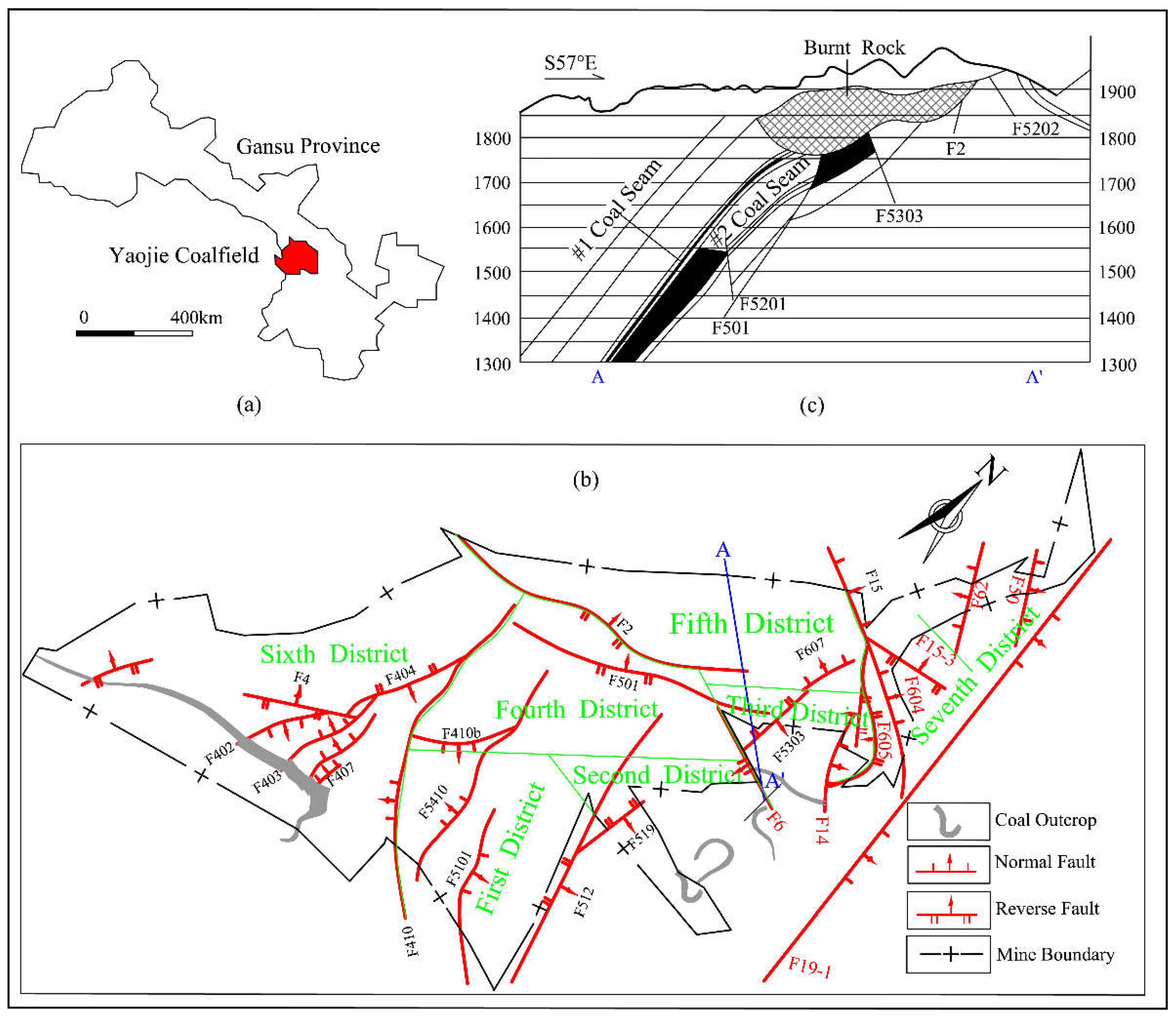
Steep and extra-thick coal seams are widely developed in northwest China, especially in coal fields such as at Yaojie, Huating and Urumqi. The location of the Yaojie coal field is shown in
Figure 1a. Yaojie No. 3 coal mine, a main recovery one, is sited at the north center of the coal field. The mine produced more than 2 million tons of coal in 2014. The mine generally shows a monoclonal structure with a northeast trend and a southwest dip, and several faults are also developed, as shown in
Figure 1b.
In the Yaojie No. 3 coal mine, the #2 coal seam is the only one with commercial value. Its thickness is approximately 24.91 m, and its dip angle is approximately 55°, i.e., the #2 coal seam is a typical steep and extra-thick one. Meanwhile, its average gas content is approximately 10 m
3/t. The schematic cross section of the #2 coal seam is shown in
Figure 1c. Moreover, several serious spontaneous combustions occurred in the shallow coal near the earth surface, which destroyed the coal’s commercial value there.
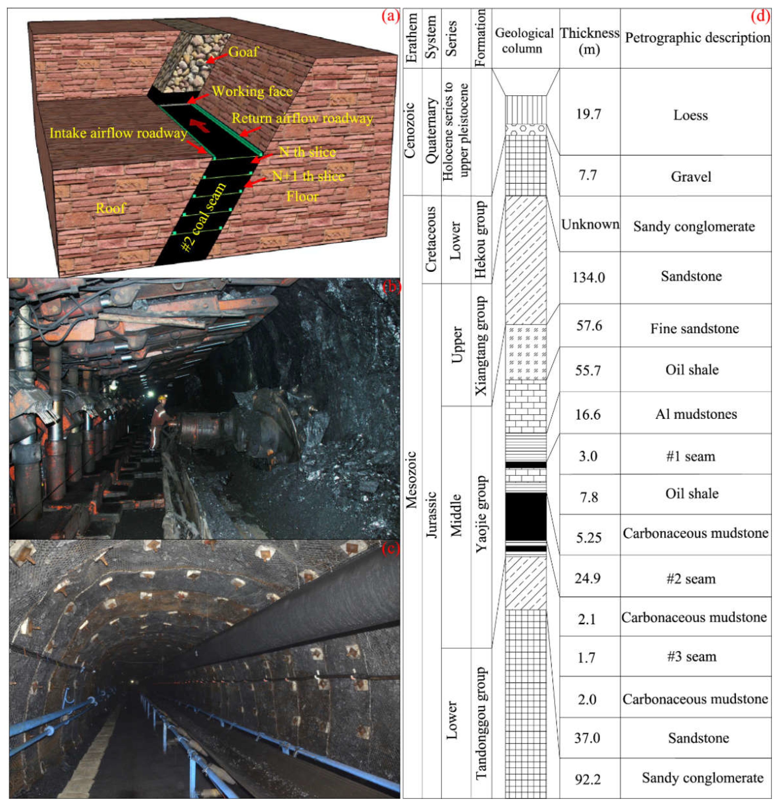
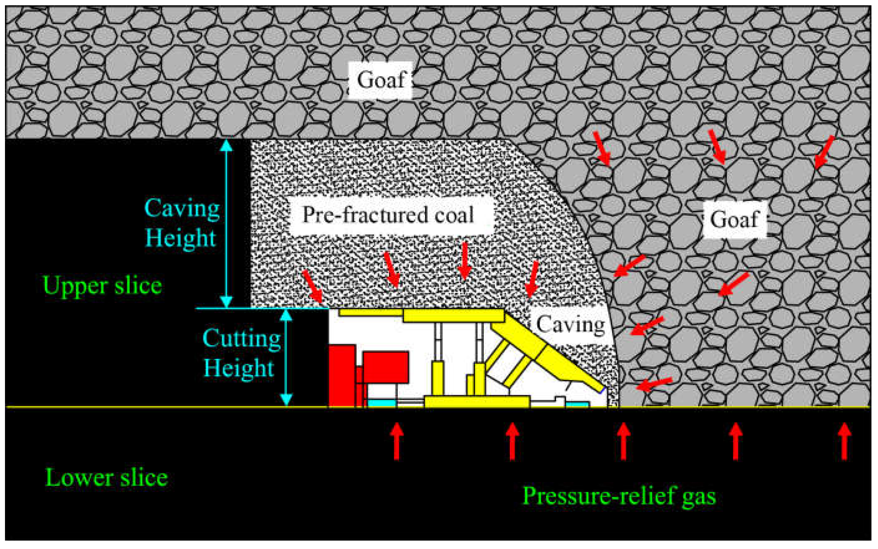
The HFMTCSC method adopted in the mining of the #2 coal seam is shown in
Figure 2a. During the mining process, the coal seam was artificially divided into different horizontal slices. In each slice, its total thickness was approximately 11.2 m, and the fully mechanized, top coal caving mining method was adopted. The mining height was approximately 2.8 m, while the caving height was approximately 8.4 m. The mining condition in each slice is shown in
Figure 2b, and the coal roadway support condition is shown in
Figure 2c. Moreover, the generalized stratigraphic column of the Yaojie No. 3 coal mine is shown in
Figure 2d.
3. Research Method
Numerical simulations, which can overcome many complicated problems in the analytical method, have been used widely in engineering and theoretical analysis in recent years [
27,
28,
29,
30]. A software based on the discrete element method and developed by Itasca Consulting Group Inc. (Minneapolis, MN, USA) [
31], 3DEC, is one of the most important numerical software tools in current rock mechanics calculations. Therefore, 3DEC software was selected to analyze the overburden movement and collapse law as well as the stress and deformation characteristics of the coal seam below the goaf during the mining of the steep and extra-thick coal seam in the HFMTCSC method.
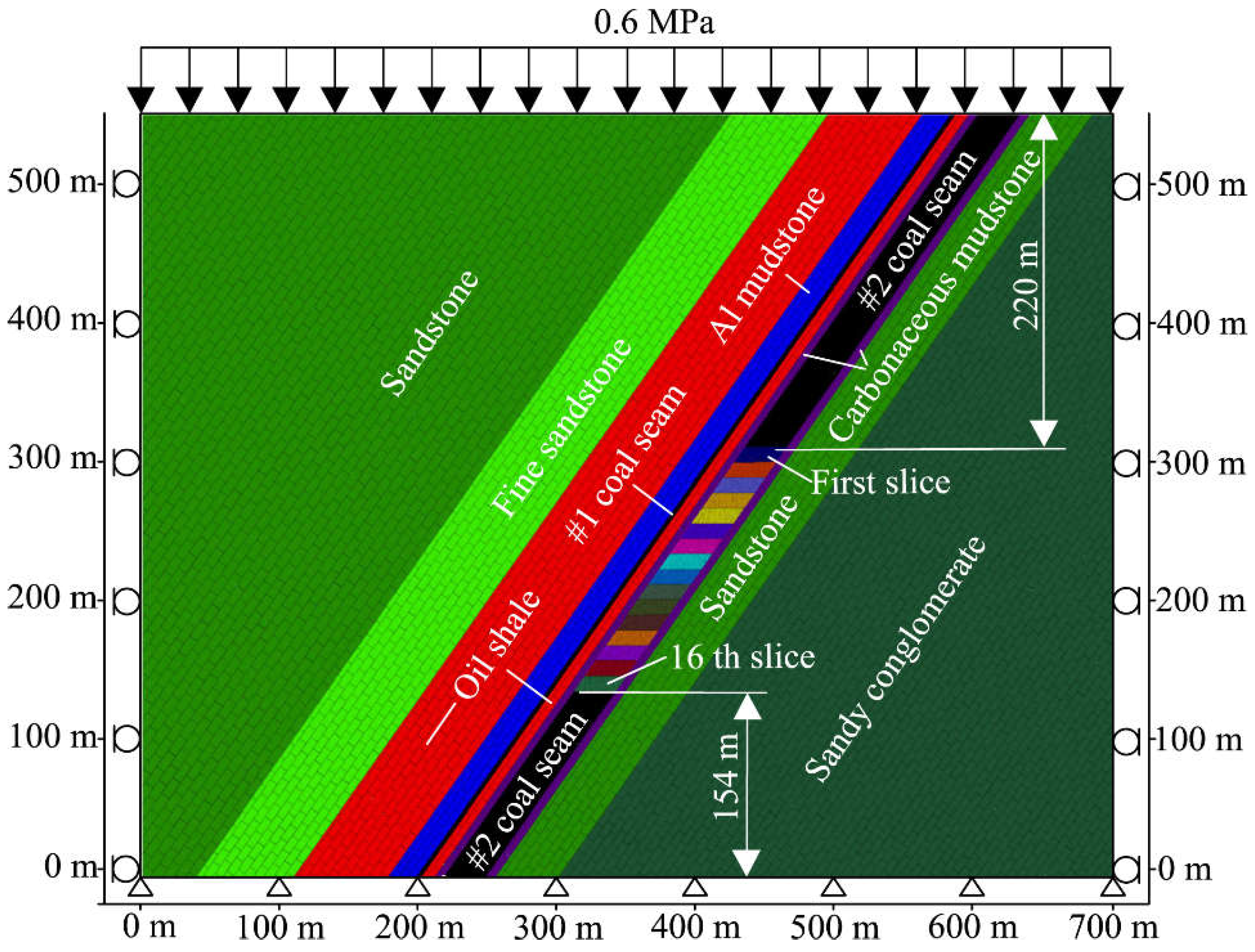
For the sake of simplification, a two-dimensional geometric model was built according to the plane strain assumption, as shown in
Figure 3. Considering that the overburden strata will move towards the goaf sharply during the mining process of the steep and extra-thick coal seam, from the shallow to the deep slice by slice, the length in the x-direction was set as 700 m while the height was set as 550 m. Meanwhile, 16 slices with an average thickness of 11 m for each were built in the geometric model. The 1st slice is located at 220 m below the top side. The 16th slice is located at 154 m above the bottom side. As for the boundary conditions, the top side was set as the stress boundary with a vertical stress of 0.6 MPa. At the same time, the horizontal displacement at the lateral and the vertical displacement at the base are constrained. The Mohr Coulomb block model and the joint area contact Coulomb slip model were used during the simulation process [
27]. The parameters of the main rock stratum and coal seams employed in the model are shown in
Table 1 and
Table 2 and were tested in the laboratory.
4. Result and Discussion
4.1. Mining-Induced Overburden Movement and Collapse Law
The numerical simulation method provides us an opportunity to observe the overburden movement during the mining of the steep and extra-thick coal seam. The movements of the overburden rock during the mining process are shown in
Figure 4.
During the mining of the first slice, the top coal and the immediate roof begin to collapse and bend towards the goaf, as shown in
Figure 4a. The caving characteristic of the top coal is in good accordance with the simulation result in the Particle Flow Code programs by [
23]. With the continual mining of the coal seam, the roof hanging distance becomes increasingly larger. During the mining of the 5th slice, the immediate roof collapses for the first time, as shown in
Figure 4b. Subsequently, the immediate roof collapses, dilates, accumulates and fills the goaf endlessly. However, the caved rock cannot completely fill in the goaf. During the mining of the 8th and the 15th slices, the main roof collapses once and again, as shown in
Figure 4c,d. Meanwhile, the goaf is gradually filled in with the periodical collapse of the main roof. Afterwards, it is difficult for the overburden rock to collapse under the support of the caved rocks filled in the goaf; thus, a new balance structure (namely a hinge structure) is formed along the dip in the overburden rock.
In a word, a pressure arch structure with an arch foot located at the coal above the goaf and the other at the coal below the goaf is formed in the overburden rock during the mining process from the 1st slice to the 14th slice. Meanwhile, a hinge structure is also formed in the overburden rock during the mining process from the 15th slice to the 16th slice.
4.2. The Pressure Relief Mechanism during the Mining of the Steep and Extra-Thick Coal Seam
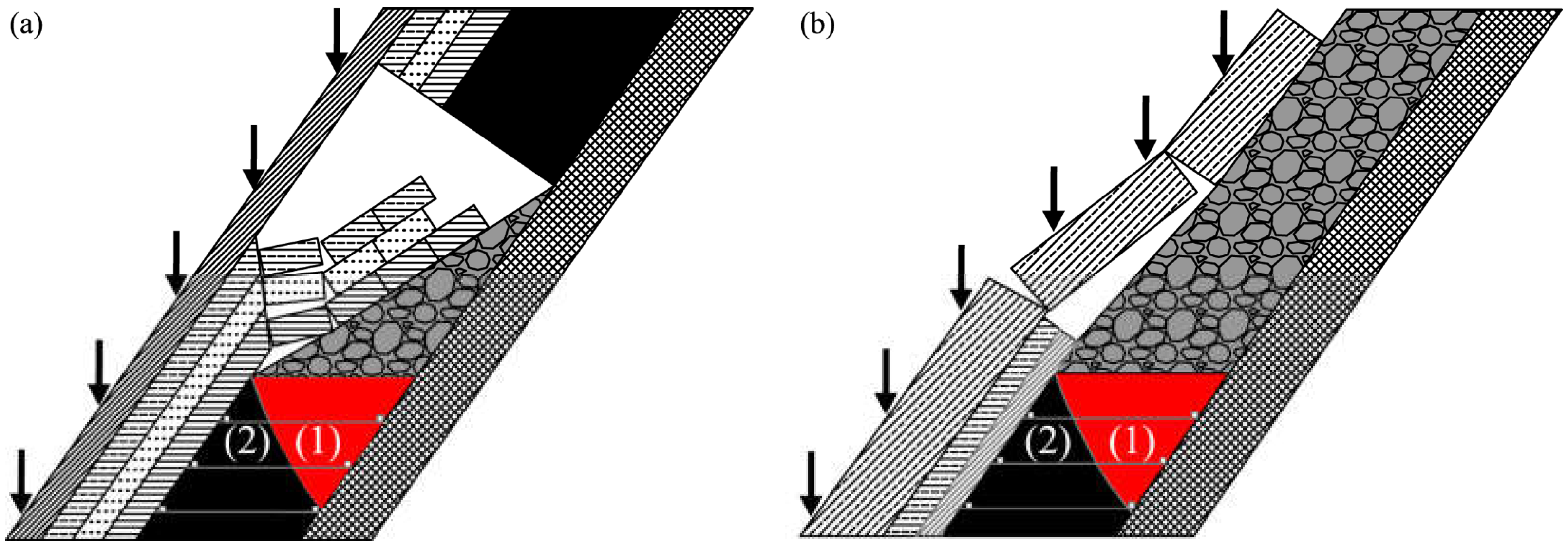
As mentioned above, a pressure arch structure and a hinge structure are formed in succession during the mining of the steep and extra-thick coal seam. In the pressure arch structure, the vertical stress it bears could be transferred to the arch feet. Therefore, a vertical stress-unloading effect could be achieved in the coal below the pressure arch structure. However, in the coal around the arch feet, there is an obvious increasing tendency in the stress, which results in a stress concentration zone. In a word, the coal below the goaf can be divided into a pressure relief zone and a stress concentration zone, as shown in
Figure 5a. A similar stress redistribution could also be achieved when the hinge structure is formed in the overburden rock (
Figure 5b): the vertical stress the hinge structure bears could also be transferred to the caved rock filled in the goaf and the coal roof; as a result, the coal below the goaf could also be divided into a pressure relief zone and a stress concentration zone. According to the above analysis, the pressure relief effect in the coal below the goaf is mainly caused by the pressure relief structure and the hinge structure formed in the overburden rock during the mining process of the steep and extra-thick coal seam.
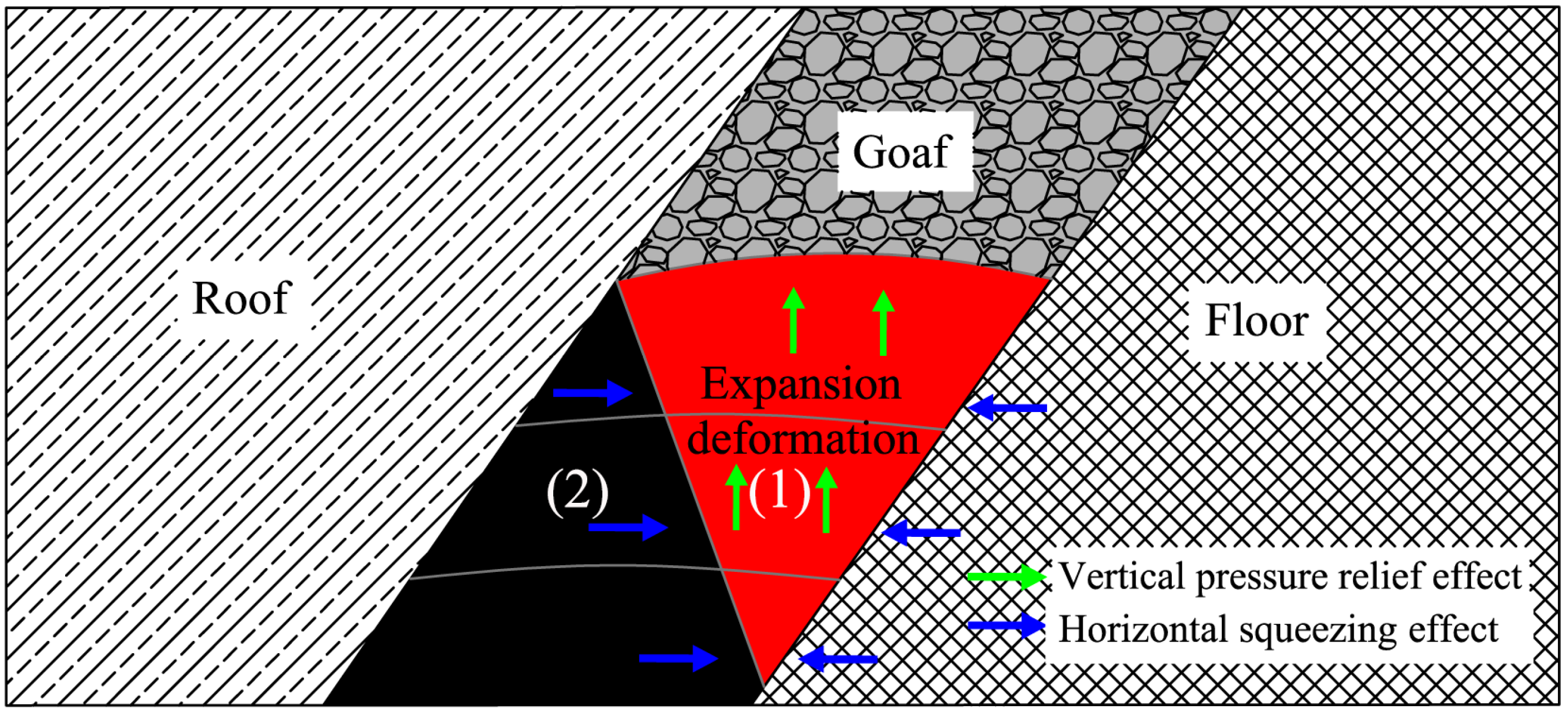
The stress redistribution could result in a coal-seam deformation. With the unloading of the vertical stress, the mechanical energy stored in the coal could be released to a certain degree. Therefore, the coal in the pressure relief zone could expand and deform towards the goaf. At the same time, the horizontal stress may increase in the stress concentration zone. Under the squeezing effect of the horizontal stress, the coal’s expansion deformation could be further enhanced. In summary, the coal in the pressure relief zone will expand and deform into the goaf under the effects of vertical pressure relief and horizontal squeezing during the mining process, as shown in
Figure 6.
4.3. Stress Evolution Characteristics in the Coal Below the Goaf
To achieve a better understanding of the stress evolution characteristics in the coal below the goaf, the vertical stress in the coal at different distances below the goaf was monitored during the mining of the steep and extra-thick coal seam.
Figure 7 illustrates the stress monitoring results during the mining of the 5th slice.
As shown in
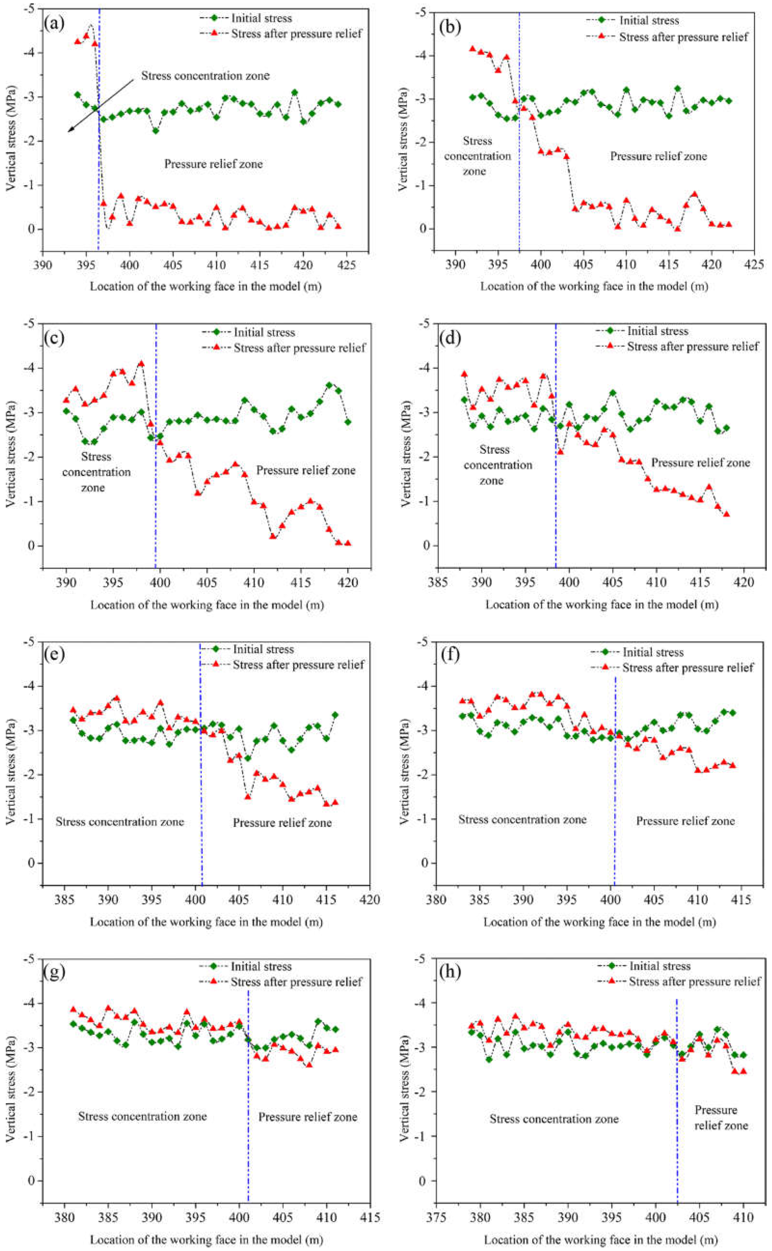
Figure 7, the vertical stress decreases in the pressure relief zone, whereas it increases in the concentration zone. Meanwhile, the pressure relief level decreases with the distance below the goaf increasing. As shown in
Figure 7a, the vertical stress in the coal 2 m below the goaf decreases to approximately 0.5 MPa during the mining of the 5th slice. However, the vertical stress in the coal at 23 m below the goaf decreases to approximately 3 MPa, as shown in
Figure 7h. At the same time, with the distance below the goaf increasing, the area of the pressure relief zone decreases while the area of the stress concentration zone increases. In China, the pressure relief angle has been widely adopted to describe the pressure relief range. According to the vertical stress monitoring results, the pressure relief angle could be obtained. As shown in
Figure 8a, the pressure relief angle is approximately 72° during the mining of the 5th slice. During the mining process of the 10th and 15th slices, the vertical stress evolutions were also monitored in the coal below the goaf. According to the stress monitoring results, their pressure relief angles could also be obtained, as shown in
Figure 8b,c. From these figures, we can see that the pressure relief angle is approximately 70° during the mining process of the 10th and 15th slices. Therefore, the pressure relief range almost remains the same during the mining process of the steep and extra-thick coal seam.
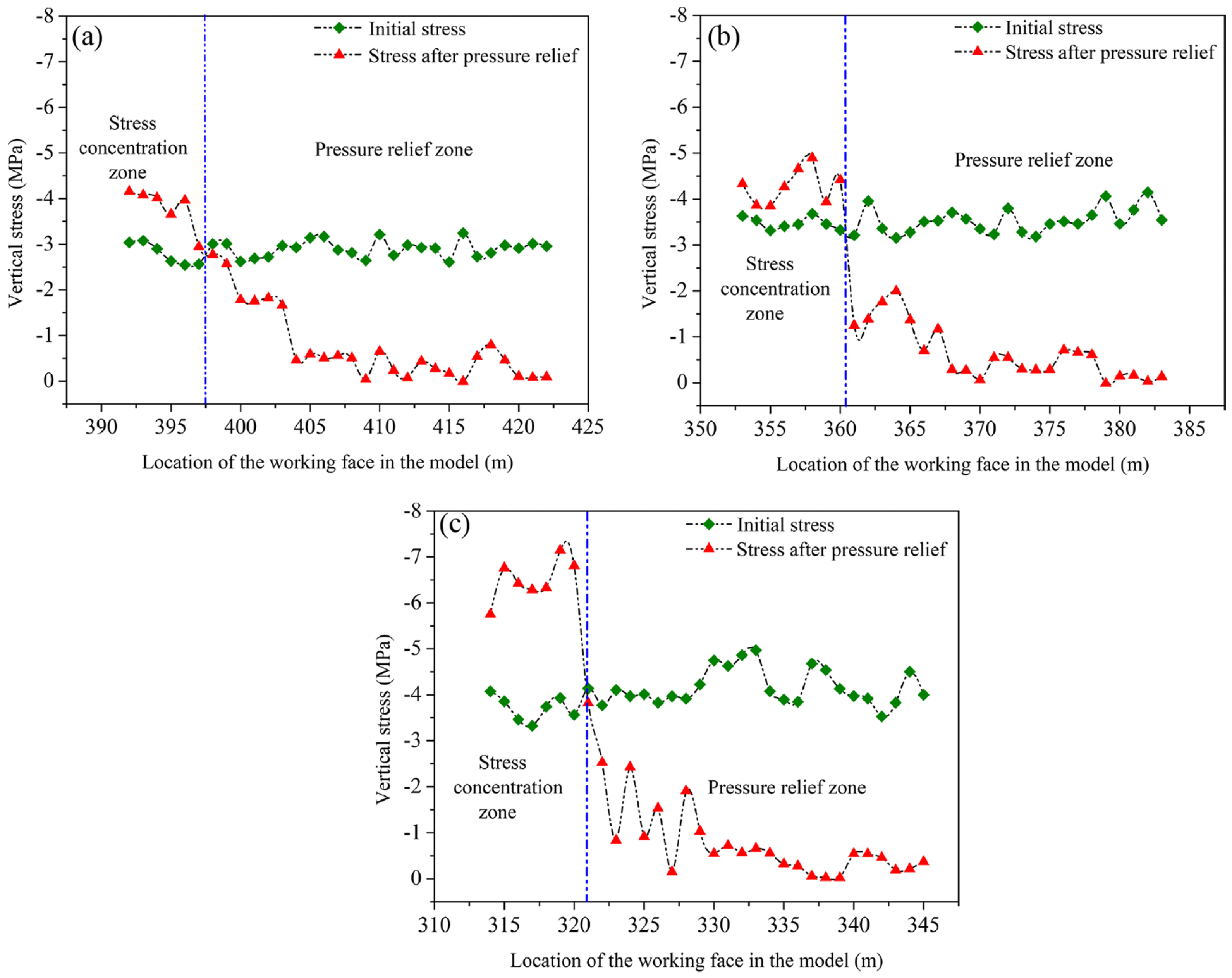
Moreover, the vertical stress is almost decreased to the same level during the mining of the different slices. The vertical stress at the same distance below the goaf was also monitored during the mining of different slices. Taking the 5th slice, the 10th slice and the 15th slice as examples, the vertical stress monitoring results at 5 m below the goaf are shown in
Figure 9. From this figure, we can see that the vertical stresses in the pressure relief zones all decrease to approximately 0.5 MPa, although the initial vertical stress is approximately 3.0 MPa, 3.5 MPa and 4.0 MPa, respectively. In contrast, the vertical stress in the stress concentration zone increases to 4.0 MPa, 4.5 MPa and 6.5 MPa, respectively. In other words, the stress concentration level increases with the mining depth.
4.4. Expansion Deformation Characteristics in the Coal Below the Goaf
As we can find in
Figure 6, the coal in the pressure relief zone will expand and deform towards the goaf under the effects of vertical pressure relief and horizontal squeezing.
Figure 10 shows the expansion deformation cloud charts in the coal below the goaf during the mining process of the 5th, 10th and 15th slices. From this figure, we can find that the expansion deformation is increasingly large with the mining depth. The largest expansion deformation in the coal below the goaf is just 120 mm during the mining of the 5th slice, whereas those of the 10th and the 15th slices increase to 150 mm and 180 mm, respectively. The reason for this is because the vertical pressure relief effect is increasingly better in the deep coal.
4.5. The Effective Pressure Relief Range
The relative expansion deformation is one of the most important evaluation indices widely used to examine the pressure relief effect of the protective layer mining technology [
11,
32]. In China, the critical relative expansion deformation is 3‰ [
17,
18,
33]. Once the relative expansion deformation in the protected layer is greater than 3‰, effective pressure relief could be achieved.
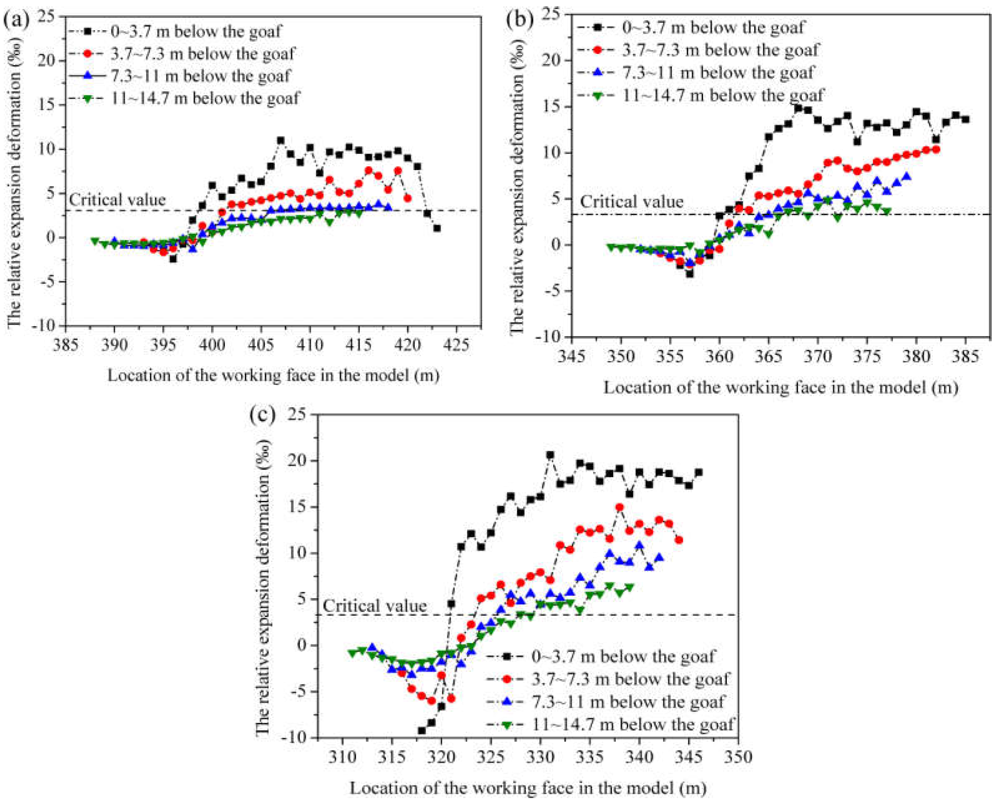
To obtain the relative expansion deformation in the coal at different distances below the goaf, we divide each slice into three sub-slices, namely, 0~3.7 m, 3.7~7.3 m and 7.3~11 m below the goaf. Hence, the relative expansion deformations of four sub-slices (0~3.7 m, 3.7~7.3 m, 7.3~11 m and 11~14.7 m below the goaf) were calculated during the mining of each slice. The expansion deformation calculation results during the mining of the 5th, 10th and 15th slices are shown in
Figure 11.
As shown in
Figure 11, with the distance below the goaf increasing, the relative expansion deformation in each sub-slice decreases gradually. For example, the relative expansion deformations in the sub-slices 0~3.7 m, 3.7~7.3 m, 7.3~11 m and 11~14.7 m below the goaf are approximately 10‰, 5‰, 3‰ and 1.5‰, respectively, as shown in
Figure 11a. The same regulation is also found during the mining of the 10th and 15th slices, as shown in
Figure 11b,c. Moreover, with the mining depth increasing, the relative expansion deformation tends to increase. Take the sub-slice 3.7~7.3 m below the goaf as an example; its relative expansion deformation is approximately 5‰ during the mining of the 5th slice, whereas it increases to approximately 9‰ and 13‰ during the mining of the 10th and 15th slices, respectively. This implies that the pressure relief effect increases with the mining depth. The effective pressure relief ranges obtained by the relative expansion deformation date are shown in
Figure 12.
As we can see from
Figure 12, the effective pressure relief range has an obvious increasing tendency with the mining depth. During the mining process of the fifth slice, the effective pressure relief angle is approximately 57°, and the effective pressure relief depth is approximately 11.0 m. Meanwhile, 75.6% of the coal in the sixth slice is located at the effective pressure relief zone. However, during the mining process of the 10th slice, the effective pressure relief angle and the effective pressure relief depth increase to 61° and 14.8 m, respectively. Moreover, 76.7% of the coal in the 11th slice is located at the effective pressure relief zone. During the mining process of the 15th slice, the effective pressure relief angle increases to 64°, and the effective pressure relief depth remains at 14.8 m, resulting in 78.2% of the coal in the 16th slice being located at the effective pressure relief zone.
Therefore, over 75% of the coal in the lower slice can be protected effectively during the mining of the upper slice in the steep and extra-thick coal seam. In other words, the steep and extra-thick coal seam can be protected effectively slice by slice during the mining process in the HFMTCSC method.
5. Gas Extraction Method and Field Application
5.1. The Gas Extraction Method
The #2 coal seam in the Yaojie No. 3 coal mine is of great outburst risk, and several serious coal and gas outburst accidents have been reported in the past few decades. At the same time, the gas originating from the coal below the goaf, the mining slice and the remaining coal in the goaf all easily migrate towards the working face during the mining process; thus, gas overflow also usually occurs in the working face. The gas emission sources in the working face are shown in
Figure 13. Therefore, pre-mining gas extraction measures should be adopted in the steep and extra-thick coal seam to eliminate the outburst hazard and decrease the gas emission in the working face.
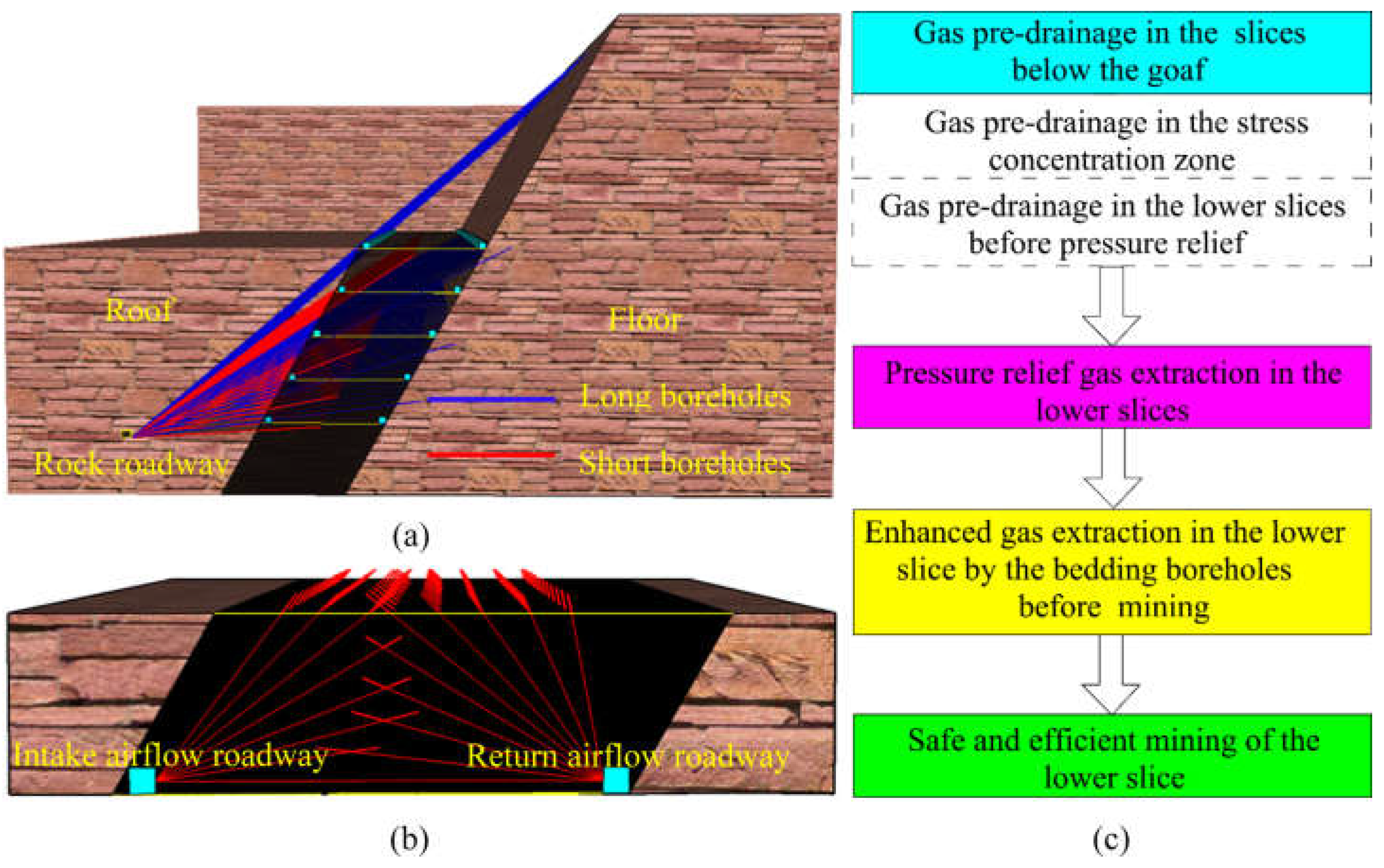
In the Yaojie No. 3 coal mine, crossing boreholes and bedding boreholes were adopted to extract the gas in the coal below the goaf. Crossing boreholes are constructed from the rock roadway in the roof, as shown in
Figure 14. Crossing boreholes are adopted to extract the gas in 4~5 slices below the goaf. Considering that the coal permeability values in the effective pressure relief zone and the stress concentration zone are rather different, the borehole spacing should also be differently set in different zones. During the actual application process, long boreholes used to extract the pressure relief gas are constructed first with an angle of 5° in the dip until all they are drilled through the coal floor. Next, enforced short boreholes are supplemented into the stress concentration zone. After the crossing boreholes are finished, the borehole spacing in the effective pressure zone is approximately 6~8 m, whereas that in the stress concentration zone is approximately 3~4 m. This arrangement of the crossing boreholes can satisfy the gas extraction demand both in the effective pressure relief zone and the stress concentration zone.
Figure 14b shows the arrangement of bedding boreholes, from which we can see that bedding boreholes with a spacing of 3 m are constructed from the roadway of the working face in each slice.
During the mining process of each slice, crossing boreholes are set to extract the gas in 4~5 slices below the goaf simultaneously. Moreover, due to the fact that the effective pressure relief depth of each slice is just approximately 11 m to 14.8 m, the stress in the 3rd~5th slices below the goaf cannot be released during the mining process. During this period, the crossing boreholes can also be adopted to extract the gas in these slices, although the permeability is relatively low. Afterwards, when the upper coal seam is exploited, the stress in these slices will be released, and the permeability will increase gradually. Then, the crossing boreholes are used to extract the pressure relief gas in these slices. Therefore, the crossing boreholes in each roof roadway are used twice during the gas extraction process, with the first time during the pre-drainage before the pressure relief and the second time during the extraction of the pressure relief gas.
The outburst risk in one to two slices below the goaf will be eliminated by the gas extraction in the crossing boreholes during the mining of each slice. Thus, the roadway of the next slice below the goaf can be excavated, and the bedding boreholes can be constructed. By the enhanced gas extraction in the bedding boreholes, the gas content in the slice to be mined next will decrease furthermore, thereby guaranteeing the safe and efficient mining in the steep and extra-thick coal seam. The flow chart of the gas extraction in the steep and extra-thick coal seam is shown in
Figure 14c.
5.2. Field Application
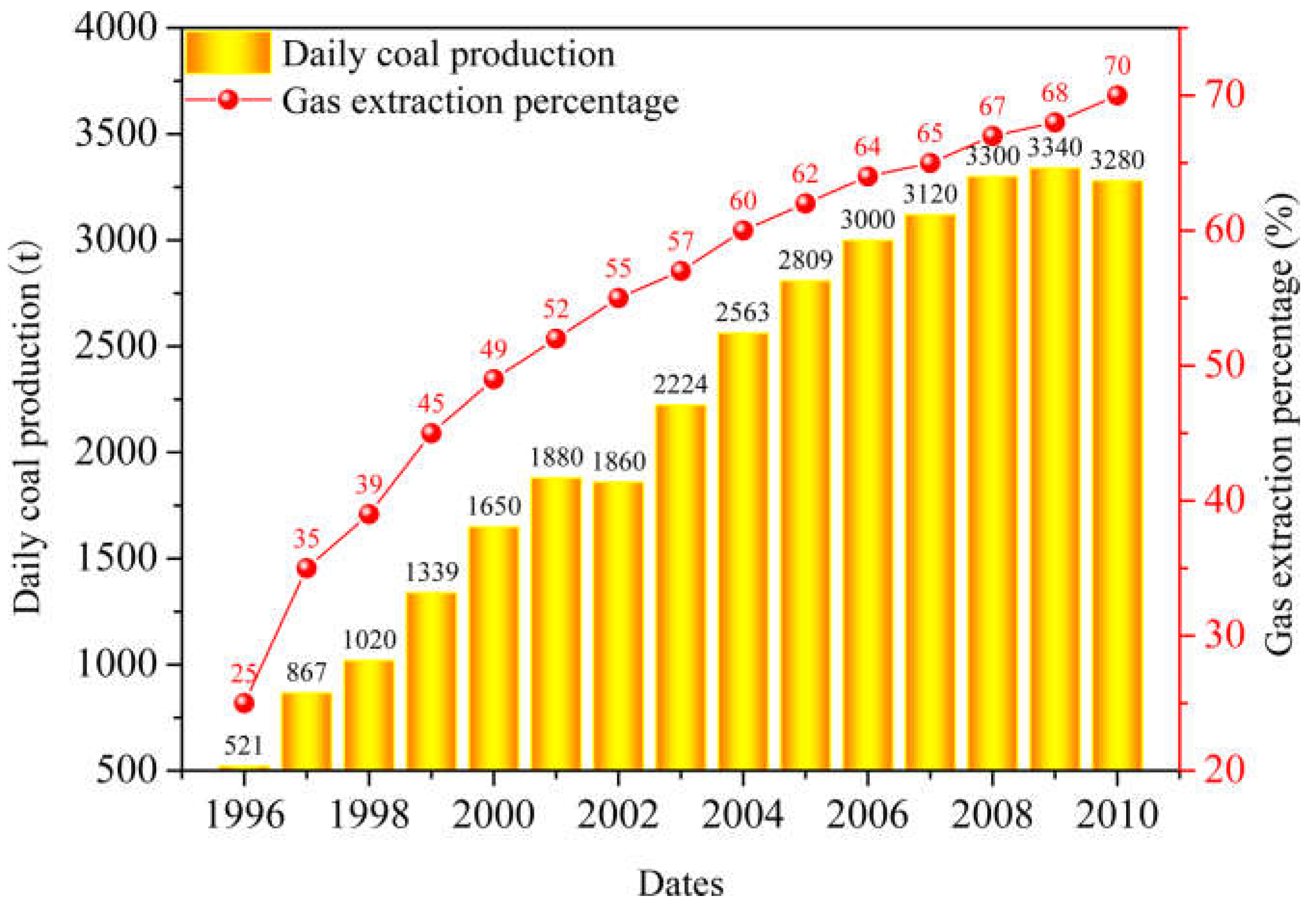
Since this gas extraction method was adopted in 1996, the gas extraction condition in the Yaojie No. 3 coal seam has improved significantly. The gas extraction percentage increased from 25% to 70%, and the daily coal production rose from 521 t to 3300 t, as shown in
Figure 15. The only coal and gas outburst accident occurred near a major fault during the mining process in 2003 [
34]. The occurrence of the fault destroyed the continuity of the coal seam; thus, the stress in coal below the goaf cannot be released effectively during the mining process. Therefore, more attention should be paid during the mining process near faults.
6. Conclusions
The following conclusions can be drawn in this work:
(1) During the mining of the steep and extra-thick coal seam, a pressure arch structure and a hinge structure are formed in succession in the overburden rock, inducing stress redistribution in the coal below the goaf. Therefore, the coal below the goaf can be divided into a pressure relief zone and a stress concentration zone.
(2) The pressure relief range with a pressure relief angle of approximately 70° in the coal below the goaf is almost the same, regardless of whether it is a pressure arch structure or a hinge structure in the overburden rock. Moreover, the vertical stress at a same distance below the goaf is decreased to the same level during the mining of different slices, whereas the stress in the stress concentration zone increases gradually with the mining depth.
(3) As the mining depth increases, the pressure relief effect in the coal below the goaf is increasingly notable and the effective pressure relief range increases gradually. When the mining depth increases from the fifth slice, the effective pressure relief angel increases from 57° to 64°, and the effective pressure relief depth increases from 11.0 m to 14.7 m.
(4) The gas in the coal below the goaf both in the effective pressure relief zone and in the stress concentration zone can be well extracted by the reasonably designed crossing boreholes and bedding boreholes. Since this gas extraction method was adopted in 1996, the gas extraction condition in the Yaojie No. 3 coal seam has improved significantly. The gas extraction percentage increased from 25% to 70%, and the daily coal production rose from 521 t to 3300 t.
Author Contributions
H.Z.: Conceptualization, methodology, writing—original draft. L.X.: Writing—review and editing. M.Y.: Writing—review and editing. C.D.: Writing—review and editing. Y.C.: Conceptualization, writing—review and editing. All authors have read and agreed to the published version of the manuscript.
Funding
This work was funded by the National Natural Science Foundation of China (No. 52104210), the Natural Science Foundation of Shanxi Province (No. 20210302124350 and No. 20210302123146) and Research Project Supported by Shanxi Scholarship Council of China (No. 2021-044).
Institutional Review Board Statement
Not applicable.
Informed Consent Statement
Not applicable.
Data Availability Statement
Data will be available from the author on request.
Acknowledgments
The authors are grateful to the editor and reviewers of this work for their insightful comments, criticisms, and suggestions.
Conflicts of Interest
The authors declare that they have no known competing financial interest or personal relationships that would have appeared to influence the work reported in this paper.
References
- Noack, K. Control of gas emissions in underground coal mines. Int. J. Coal Geol. 1998, 35, 57–82. [Google Scholar] [CrossRef]
- Aguado, M.B.D.; Nicieza, C.G. Control and prevention of gas outbursts in coal mines, Riosa–Olloniego coalfield, Spain. Int. J. Coal Geol. 2007, 69, 253–266. [Google Scholar] [CrossRef]
- Yang, W.; Lin, B.; Qu, Y.; Li, Z.; Zhai, C.; Jia, L.; Zhao, W. Stress evolution with time and space during mining of a coal seam. Int. J. Rock Mech. Min. Sci. 2011, 48, 1145–1152. [Google Scholar] [CrossRef]
- Moore, T.A. Coalbed methane: A review. Int. J. Coal Geol. 2012, 101, 36–81. [Google Scholar] [CrossRef]
- Saghafi, A.; Pinetown, K.L. A new method to determine the depth of the de-stressed gas-emitting zone in the underburden of a longwall coal mine. Int. J. Coal Geol. 2015, 152, 156–164. [Google Scholar] [CrossRef]
- Wang, L.; Lu, Z.; Chen, D.; Liu, Q.; Wen, Z. Safe strategy for coal and gas outburst prevention in deep-and-thick coal seams using a soft rock protective layer mining. Saf. Sci. 2020, 129, 104800. [Google Scholar] [CrossRef]
- Xu, C.; Yang, G.; Wang, K.; Fu, Q. Uneven stress and permeability variation of mining-disturbed coal seam for targeted CBM drainage: A case study in Baode coal mine, eastern Ordos Basin, China. Fuel 2021, 289, 119911. [Google Scholar] [CrossRef]
- Wang, H.; Cheng, Y.; Wu, D.; Liu, H. Gas emission and parameter optimization of gas extraction in mining face of short distance protective seam. J. China Coal Soc. 2010, 4, 590–594. (In Chinese) [Google Scholar]
- Liu, H.; Cheng, Y.; Chen, H.; Mou, J.; Kong, S. Characteristics of mining gas channel expansion in the remote overlying strata and its control of gas flow. Int. J. Min. Sci. Technol. 2013, 23, 481–487. [Google Scholar] [CrossRef]
- Zhang, R.; Cheng, Y.; Zhou, H.; Yuan, L.; Li, W.; Liu, Q.; Jin, K.; Tu, Q. New insights into the permeability-increasing area of overlying coal seams disturbed by the mining of coal. J. Nat. Gas Sci. Eng. 2018, 48, 352–364. [Google Scholar] [CrossRef]
- Hu, G.; Wang, H.; Li, X.; Fan, X.; Yuan, Z. Numerical simulation of protection range in exploiting the upper protective layer with a bow pseudo-incline technique. Min. Sci. Technol. 2009, 19, 58–64. (In Chinese) [Google Scholar] [CrossRef]
- Yang, W.; Lin, B.; Qu, Y.; Zhao, S.; Zhai, C.; Jia, L.; Zhao, W. Mechanism of strata deformation under protective seam and its application for relieved methane control. Int. J. Coal Geol. 2011, 85, 300–306. [Google Scholar] [CrossRef]
- Li, D. Underground hydraulic mining of thin sub-layer as protective coal seam in coal mines. Int. J. Rock Mech. Min. Sci. 2014, 67, 145–154. [Google Scholar] [CrossRef]
- Liu, H.; Liu, H.; Cheng, Y. The elimination of coal and gas outburst disasters by ultrathin protective seam drilling combined with stress-relief gas drainage in Xinggong coalfield. J. Nat. Gas Sci. Eng. 2014, 21, 837–844. [Google Scholar] [CrossRef]
- Kong, S.; Cheng, Y.; Ren, T.; Liu, H. A sequential approach to control gas for the extraction of multi-gassy coal seams from traditional gas well drainage to mining-induced stress relief. Appl. Energy 2014, 131, 67–78. [Google Scholar] [CrossRef]
- Yuan, Y.; Chen, Z.; Zhang, X.; Wang, Z. Intermediate coal pillar instability and permeability evolution in extremely thin protective seam by auger mining. Arab. J. Geosci. 2019, 12, 322. [Google Scholar] [CrossRef]
- Xu, Y.; Lun, Z.; Pan, Z.; Wang, H.; Zhou, X.; Zhao, C.; Zhang, D. Occurrence space and state of shale oil: A review. J. Pet. Sci. Eng. 2022, 211, 110183. [Google Scholar] [CrossRef]
- Zhang, H.; Cheng, Y.; Deng, C.; Shu, L.; Pan, Z.; Yuan, L.; Wang, L.; Liu, Q. A novel in-seam borehole discontinuous hydraulic flushing technology in the driving face of soft coal seams: Enhanced gas extraction mechanism and field application. Rock Mech. Rock Eng. 2022, 55, 885–907. [Google Scholar] [CrossRef]
- Tu, S.; Yuan, Y.; Li, N.; Dou, F.; Wang, F. Hydraulic support stability control of fully mechanized top coal caving face with steep coal seams based on instable critical angle. J. Coal Sci. Eng. 2008, 14, 382–385. (In Chinese) [Google Scholar] [CrossRef]
- Wang, N.; Li, L.; Lai, X.; Chai, X. Comprehensive analysis of safe mining to heavy and steep coal seam under complex geophysics environment. J. Coal Sci. Eng. 2008, 14, 378–381. (In Chinese) [Google Scholar] [CrossRef]
- Zhang, J.; Zhao, Z.; Gao, Y. Research on top coal caving technique in steep and extra-thick coal seam. Procedia Earth Planet. Sci. 2011, 2, 145–149. [Google Scholar] [CrossRef] [Green Version]
- Lai, X.; Shan, P.; Cao, J.; Sun, H.; Suo, Z.; Cui, F. Hybrid assessment of pre-blasting weakening to horizontal section top coal caving (HSTCC) in steep and thick seams. Int. J. Min. Sci. Technol. 2014, 24, 31–37. [Google Scholar] [CrossRef]
- Miao, S.; Lai, X.; Cui, F. Top coal flows in an excavation disturbed zone of high section top coal caving of an extremely steep and thick seam. Min. Sci. Technol. 2011, 21, 99–105. (In Chinese) [Google Scholar]
- Zhao, J.; Lai, X. Application of preblasting to high-section top coal caving for steep-thick coal seam. J. Coal Sci. Eng. 2011, 17, 113–118. (In Chinese) [Google Scholar] [CrossRef]
- Karacan, C.Ö.; Ruiz, F.A.; Cotè, M.; Phipps, S. Coal mine methane: A review of capture and utilization practices with benefits to mining safety and to greenhouse gas reduction. Int. J. Coal Geol. 2011, 86, 121–156. [Google Scholar] [CrossRef]
- Li, W.; Cheng, Y.; Wang, L. The origin and formation of CO2 gas pools in the coal seam of the Yaojie coalfield in China. Int. J. Coal Geol. 2011, 85, 227–236. [Google Scholar] [CrossRef]
- Wang, W.; Cheng, Y.; Wang, H.; Liu, H.; Wang, L.; Li, W.; Jiang, J. Fracture failure analysis of hard–thick sandstone roof and its controlling effect on gas emission in underground ultra-thick coal extraction. Eng. Fail. Anal. 2015, 54, 150–162. [Google Scholar] [CrossRef]
- Tang, C.; Kaiser, P. Numerical simulation of cumulative damage and seismic energy release during brittle rock failure—part I: Fundamentals. Int. J. Rock Mech. Min. Sci. 1998, 35, 113–121. [Google Scholar] [CrossRef]
- Nadimi, S.; Shahriar, K.; Sharifzadeh, M.; Moarefvand, P. Triaxial creep tests and back analysis of time-dependent behavior of Siah Bisheh cavern by 3-Dimensional Distinct Element Method. Tunn. Undergr. Space Technol. 2011, 26, 155–162. [Google Scholar] [CrossRef]
- Coggan, J.; Gao, F.; Stead, D.; Elmo, D. Numerical modelling of the effects of weak immediate roof lithology on coal mine roadway stability. Int. J. Coal Geol. 2012, 90, 100–109. [Google Scholar] [CrossRef]
- Itasca. 3DEC-3-Dimensional Distinct Element Code; Version 4.10; Itasca Consulting Group: Minneapolis, MN, USA, 2013. [Google Scholar]
- Wang, L.; Wang, Z.; Xu, S.; Zhou, W.; Wu, J. A field investigation of the deformation of protected coal and its application for CBM extraction in the Qinglong coalmine in China. J. Nat. Gas Sci. Eng. 2015, 27, 367–373. [Google Scholar] [CrossRef]
- Liu, H.; Cheng, Y. The elimination of coal and gas outburst disasters by long distance lower protective seam mining combined with stress-relief gas extraction in the Huaibei coal mine area. J. Nat. Gas Sci. Eng. 2015, 27, 346–353. [Google Scholar] [CrossRef]
- Cao, J.; Dou, L.; Zhu, G.; He, J.; Wang, S.; Zhou, K. Mechanism of rock burst in horizontal section mining of a steeply inclined extra-thick coal seam and prevention technology. Energies 2020, 13, 6043. [Google Scholar] [CrossRef]
Figure 1.
The location and the geological setting of the Yaojie No.3 coal mine: (a) location of the Yaojie coalfield; (b) geological setting of the Yaojie No.3 coal mine and (c) schematic cross section along the line A-A′ in (b).
Figure 1.
The location and the geological setting of the Yaojie No.3 coal mine: (a) location of the Yaojie coalfield; (b) geological setting of the Yaojie No.3 coal mine and (c) schematic cross section along the line A-A′ in (b).
Figure 2.
Mining method and generalized stratigraphic column in the Yaojie No. 3 coal mine: (a) schematic view of the HFMTCSC mining method; (b) mining condition; (c) coal roadway support condition and (d) the stratigraphic column.
Figure 2.
Mining method and generalized stratigraphic column in the Yaojie No. 3 coal mine: (a) schematic view of the HFMTCSC mining method; (b) mining condition; (c) coal roadway support condition and (d) the stratigraphic column.
Figure 3.
Geometric model.
Figure 3.
Geometric model.
Figure 4.
The motion states of the overburden rocks during the mining process: (a) the first slice; (b) the 5th slice; (c) the 8th slice and (d) the 15th slice.
Figure 4.
The motion states of the overburden rocks during the mining process: (a) the first slice; (b) the 5th slice; (c) the 8th slice and (d) the 15th slice.
Figure 5.
The stress redistribution mechanism of the steep and extra-thick coal seam: (a) the pressure arch structure stage and (b) the hinge structure stage. In both figures: (1) denotes the pressure relief zone, and (2) denotes the stress concentration zone.
Figure 5.
The stress redistribution mechanism of the steep and extra-thick coal seam: (a) the pressure arch structure stage and (b) the hinge structure stage. In both figures: (1) denotes the pressure relief zone, and (2) denotes the stress concentration zone.
Figure 6.
The expansion deformation mechanism: (1) denotes the pressure relief zone, and (2) denotes the stress concentration zone.
Figure 6.
The expansion deformation mechanism: (1) denotes the pressure relief zone, and (2) denotes the stress concentration zone.
Figure 7.
Vertical stress monitoring results during the mining of the 5th slice: (a) 2 m below the goaf; (b) 5 m below the goaf; (c) 8 m below the goaf; (d) 11 m below the goaf; (e) 14 m below the goaf; (f) 17 m below the goaf; (g) 20 m below the goaf and (h) 23 m below the goaf.
Figure 7.
Vertical stress monitoring results during the mining of the 5th slice: (a) 2 m below the goaf; (b) 5 m below the goaf; (c) 8 m below the goaf; (d) 11 m below the goaf; (e) 14 m below the goaf; (f) 17 m below the goaf; (g) 20 m below the goaf and (h) 23 m below the goaf.
Figure 8.
Pressure relief range in the coal below the goaf: (a) the 5th slice, (b) the 10th slice and (c) the 15th slice. In each figure, (1) denotes the pressure relief zone, and (2) denotes the stress concentration zone.
Figure 8.
Pressure relief range in the coal below the goaf: (a) the 5th slice, (b) the 10th slice and (c) the 15th slice. In each figure, (1) denotes the pressure relief zone, and (2) denotes the stress concentration zone.
Figure 9.
The change of the vertical stress in the coal 5 m below the goaf: (a) the 5th slice, (b) the 10th slice and (c) the 15th slice.
Figure 9.
The change of the vertical stress in the coal 5 m below the goaf: (a) the 5th slice, (b) the 10th slice and (c) the 15th slice.
Figure 10.
The expansion deformation cloud charts in the coal below the goaf: (a) the 5th slice; (b) the 10th slice and (c) the 15th slice.
Figure 10.
The expansion deformation cloud charts in the coal below the goaf: (a) the 5th slice; (b) the 10th slice and (c) the 15th slice.
Figure 11.
The relative expansion deformation calculation results: (a) the 5th slice, (b) the 10th slice and (c) the 15th slice.
Figure 11.
The relative expansion deformation calculation results: (a) the 5th slice, (b) the 10th slice and (c) the 15th slice.
Figure 12.
The effective pressure relief ranges in the coal below the goaf: (a) the 5th slice, (b) the 10th slice and (c) the 15th slice. In each figure: (1) denotes the effective pressure relief zone, and (2) denotes the stress concentration zone.
Figure 12.
The effective pressure relief ranges in the coal below the goaf: (a) the 5th slice, (b) the 10th slice and (c) the 15th slice. In each figure: (1) denotes the effective pressure relief zone, and (2) denotes the stress concentration zone.
Figure 13.
The gas emission sources in the working face.
Figure 13.
The gas emission sources in the working face.
Figure 14.
Schematic view of the gas extraction in the steep and extra-thick coal seam: (a) crossing boreholes from the rock roadway in the roof; (b) bedding boreholes from the roadway of the working face; and (c) the gas extraction flow chart.
Figure 14.
Schematic view of the gas extraction in the steep and extra-thick coal seam: (a) crossing boreholes from the rock roadway in the roof; (b) bedding boreholes from the roadway of the working face; and (c) the gas extraction flow chart.
Figure 15.
The gas extraction percentage and daily coal production in recent years.
Figure 15.
The gas extraction percentage and daily coal production in recent years.
Table 1.
Physical and mechanics properties of the rocks and coal blocks.
Table 1.
Physical and mechanics properties of the rocks and coal blocks.
| Rock Strata | Density
(kg/m³) | Bulk Modulus
(GPa) | Shear Modulus
(GPa) | Cohesion
(MPa) | Friction Angle
(°) | Tensile Strength
(MPa) |
|---|
| Sandstone | 2600 | 8.7 | 8.3 | 6.0 | 35 | 9.0 |
| Fine sandstone | 2600 | 7.8 | 4.9 | 8.3 | 38 | 13.1 |
| Oil shale | 2100 | 3.3 | 3.4 | 2.3 | 39 | 3.5 |
| Al mudstones | 2500 | 3.0 | 3.0 | 1.6 | 27 | 4.5 |
| Coal seam | 1400 | 0.8 | 0.8 | 1.2 | 30 | 2.5 |
| Carbonaceous mudstone | 1250 | 2.6 | 1.3 | 2.3 | 42 | 3.2 |
| Sandy conglomerate | 2750 | 10.5 | 6.3 | 7.1 | 40 | 9.4 |
Table 2.
Physical and mechanics properties of the rocks and coal joints.
Table 2.
Physical and mechanics properties of the rocks and coal joints.
| Rock Strata | Normal Stiffness
(GPa) | Shear Stiffness
(GPa) | Cohesion
(MPa) | Friction Angle
(°) | Tensile Strength
(MPa) |
|---|
| Sandstone | 20.0 | 19.0 | 1.2 | 18 | 12.3 |
| Fine sandstone | 29.0 | 27.0 | 1.8 | 21 | 8.5 |
| Oil shale | 16.0 | 16.0 | 1.0 | 15 | 4.5 |
| Al mudstones | 35.0 | 34.5 | 0.6 | 18 | 4.2 |
| Coal seam | 24.0 | 23.5 | 0.5 | 12 | 1.5 |
| Carbonaceous mudstone | 22.0 | 20.0 | 0.8 | 22 | 3.5 |
| Sandy conglomerate | 19.0 | 18.0 | 1.5 | 20 | 10.2 |
| Publisher’s Note: MDPI stays neutral with regard to jurisdictional claims in published maps and institutional affiliations. |
© 2022 by the authors. Licensee MDPI, Basel, Switzerland. This article is an open access article distributed under the terms and conditions of the Creative Commons Attribution (CC BY) license (https://creativecommons.org/licenses/by/4.0/).


