
Dust Control Technology in Dry Directional Drilling in Soft and Broken Coal Seams

1
Yongcheng Vocational College, Yongcheng 476600, China
2
State Key Laboratory of Coal Resources and Safe Mining, China University of Mining and Technology, Xuzhou 221116, China
3
CCTEG Chongqing Research Institute, Chongqing 400037, China
*
Author to whom correspondence should be addressed.
Energies 2022, 15(10), 3804; https://0-doi-org.brum.beds.ac.uk/10.3390/en15103804
Submission received: 14 April 2022
/
Revised: 11 May 2022
/
Accepted: 20 May 2022
/
Published: 21 May 2022
(This article belongs to the Special Issue New Challenges in the Utilization of Underground Energy and Space)
Abstract
:High rate of dust generation and serious dust diffusion in dry directional drilling in soft and broken coal seams (SBCS) have long been critical problems in the mining process. To solve these problems, in this study, a dust hood was designed and applied to realize non-contact dust control in drilling holes. The optimal performance of the dust hood was achieved when different technical parameters, including the gap width between the dust hood and the drill pipe, the air-slot width of the sealing device, the slag discharge pressure, and the air curtain pressure were controlled at 2 mm, 0.2 mm, 0.3 MPa, and 0.5 MPa, respectively. As a result, the dust concentration was reduced from 540 mg/m3 to 15 mg/m3, with dust control efficiency reaching 97.2%. The in situ test results confirmed good dust control effects, as the dust control efficiency reached 98.3% after using the dust hood.
1. Introduction
Pre-draining coal seam gas with long boreholes is one of the effective measures to control coal seam gas in China [1,2,3,4]. At present, wet drilling and dry drilling are two of the methods mainly adopted for long boreholes in coal seams [5,6,7]. Wet drilling generates less dust powder but has problems with drilling jams, hole collapse, and sewage disposal [8,9]. Dry drilling, especially air directional drilling, has obvious advantages, such as short operation period, low cost, and good gas drainage effect, and, therefore, is widely used for gas drainage [10,11,12]. However, when air directional drilling is used in soft and broken coal seams (SBCSs), fine dust diffusion around the borehole is significant [13,14,15,16,17], and causes severe dust pollution in the drilling space, which endangers the safety of mine production and the health of operators [18,19,20,21,22].
At present, different methods are used to control dust diffusion in dry drilling, mainly including the spraying method, wet net method, optimizing ventilation parameters, etc. Dai researched a dust-catching technology and mechanism using ultrasonic atomization. The principle was to use ultrasonic waves to atomize water into dense micro-droplets with a diameter of only 1–50 μm, and the droplets captured and condensed fine dust in a partially closed dust-generating space [23]. Spray systems cannot meet dust-suppression requirements of super high mining face. Responding to this challenge, You developed a wet net method by installing densely arranged wet nets in the return airway to control dust, which had important references for dust prevention and control in fully mechanized mining faces with super-large mining heights [24]. Xie et al. used FLUENT software to simulate airflow–dust migration characteristics and analyzed the effect of the installation position of forced air ducts on the airflow–dust migration behavior in a subway tunnel [25,26,27]. Liu carried out a numerical analysis on respiratory dust reduction using a vortex ventilation system in a mining face and revealed its good ventilation performance [28]. Although the existing dust suppression methods can inhibit the diffusion of dust to a certain extent, they do not prevent the generation of dust at the source, and dust spread into roadways has already endangered the health of drilling operators. Therefore, it is necessary to develop devices to suppress dust at the drilling hole. In 1996, Chen invented a dust collector that sucked the dust generated at the drilling hole with compressed air ejection. However, the small negative pressure generated by the ejector failed to achieve the expected dust control effect [29]. Guo optimized this method and developed a GZC-type dry-drilling dust collector, which had much stronger negative pressure generated from an air motor. However, the energy consumption of air motors was massive, while the air volume was very low, so the dust control efficiency was still not satisfactory [30].
At present, there is no report on a simple and efficient dust control device that can be installed at the drilling hole, and specifically, no relevant research has been conducted on non-contact dust hoods. To solve the problems of high dust concentration and dust diffusion in drilling in SBCS, in this study, a non-contact dust control system for drilling was proposed, and a dust hood with a sealing function was designed accordingly. With this dust hood, several tests were conducted to obtain the key process parameters for the best dust control effect, and the dust control efficiency in field application reached 98.3%.
The rest of this paper is structured as follows: In Section 2, the size distribution of coal-dust particles is analyzed during dry drilling in Qinglong Coal Mine, and a dust control system for directional drilling in SBCS is introduced. In Section 3, the best-obtained dust control parameters from an optimization experiment on the dust control system are presented. In Section 4, the results of a field test conducted to verify the effect of the dust hood are provided. Section 5 is the conclusion.
2. Dust Hazard and Control System
In this section, we discuss the results of an analysis we performed on the motion of dust particles in airflow, as well as test results of the particle size distribution of coal dust during dry drilling in the Qinglong Coal Mine. In order to deal with dust hazards, we designed a non-contact dust control system comprising a dust-collecting hood with a sealing function.
2.1. The Motion of Dust Particles in Air Flow
Air resistance and gravity are the two most influential yet opposing forces of dust movement, under which dust diffuses or settles. Even though in real conditions, dust does not have spherical particles, in this research, we assumed dust particles to be spheres of uniform texture, with the same diameter in all directions, to analyze the dust movement in the air. The force analysis of the settlement process of dust particles is as follows:
The gravity of dust particles is determined by
where F1 is gravity on dust particles; mp is the mass of dust particles; g is gravitational acceleration; dp is the diameter of dust particles; ρp is the density of dust particles.
The buoyancy of dust particles is found by
where F2 is the buoyancy of dust particles; ma is the mass of air; ρa is the density of air.
The resistance direction of dust particles in the roadway is opposite to the direction of dust movement. The resistance of dust particles with diameter dp in the process of settling at relative velocity v is as follows:
where F3 is the resistance of dust particles; Ψ is the drag coefficient of air.
Since buoyancy and gravity are in opposite directions, the resultant force F of the two is
When dust particles begin to settle, both the settling velocity and the resistance (F3) to dust particles are quite small. If F > F3, the settlement of dust particles accelerates.
According to Equation (4), dust particles with smaller diameters tend to reach the force balance faster, which will slow down their settling. Therefore, under the condition of constant wind speed, dust particles with smaller diameters will diffuse farther.
2.2. Dust Hazard of Dry Directional Drilling in Coal Seams
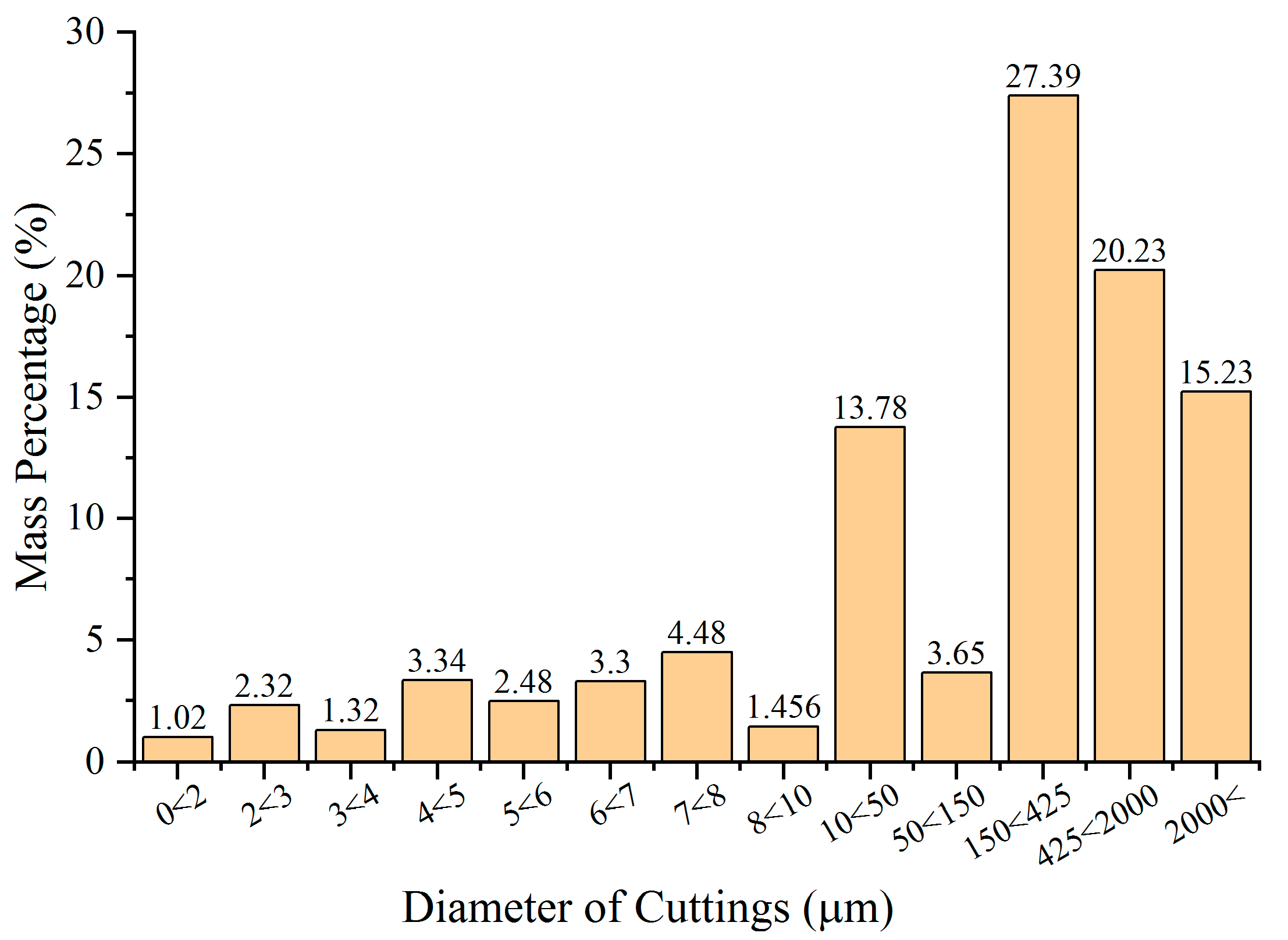
Normally, power for the air screw motor in dry directional drilling is provided by a special air compressor. However, the high nominal pressure and flow rate of the air compressor usually cause serious dust diffusion, which, in turn, pushes high the dust concentration at the drilling site [15]. For example, dust concentration at a distance of 1 m from the borehole during dry directional drilling of SBCS in the Qinglong Coal Mine was found to reach more than 2000 mg/m3 when no dust control measures were taken. Further particle size analysis on drilling cuttings (Figure 1) showed that the dry directional drilling cuttings of less than 10 μm took a fairly large proportion, reaching 19.72% in mass percentage. As particles with smaller diameters may diffuse farther, dry drilling in SBCS is harmful due to high dust concentration and rich, fine particles.
2.3. Dust Control System in Drilling
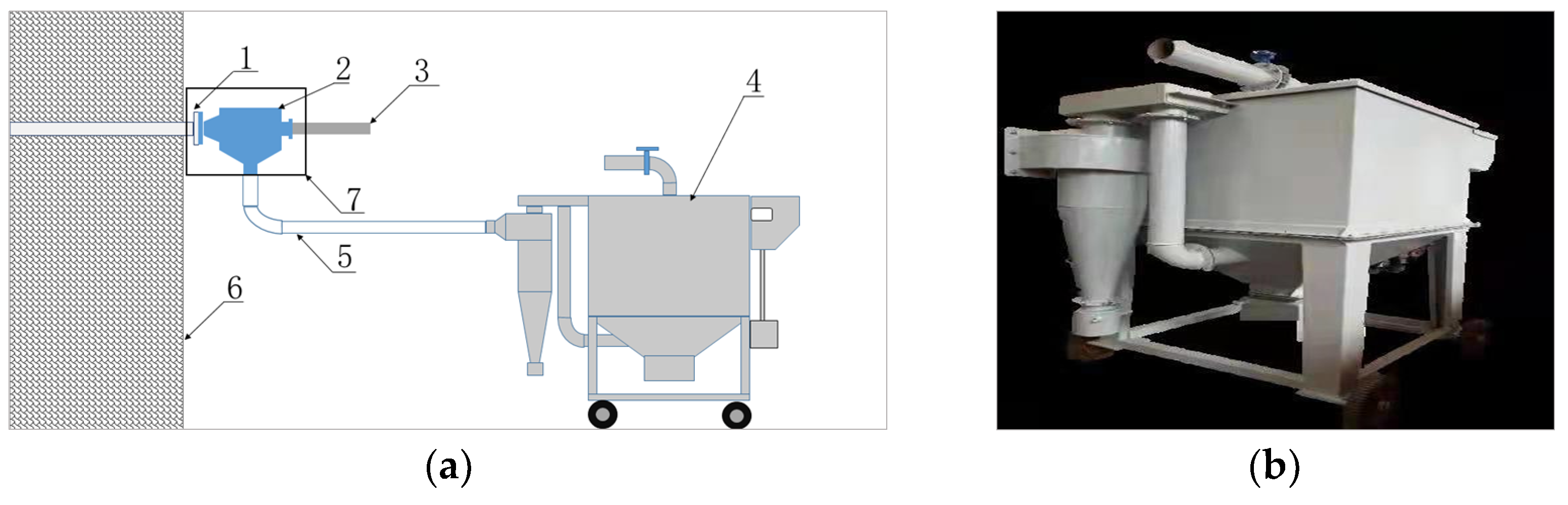
A non-contact dust control system comprising a dust-collecting hood with a sealing function was proposed in this research to reduce dust diffusion in roadways. This equipment can seal the gap between the dust-collecting hood and the drill pipe and, thus, ensure the complete collection of dust from the drilling hole. The structure of the dust hood is shown in Figure 2, and the dust control system for directional drilling in SBCS is shown in Figure 3.
The dust-hood flange is connected to the flange of the extraction pipeline that is pre-embedded in the directional drilling hole, and the compressed air passes through the slot of the sealing device in the dust hood to generate an annular “air curtain”, which seals the gap between the dust hood and the drill pipe in a non-contact way. This measure can effectively prevent dust from spreading to roadways, so as to reduce dust hazards.
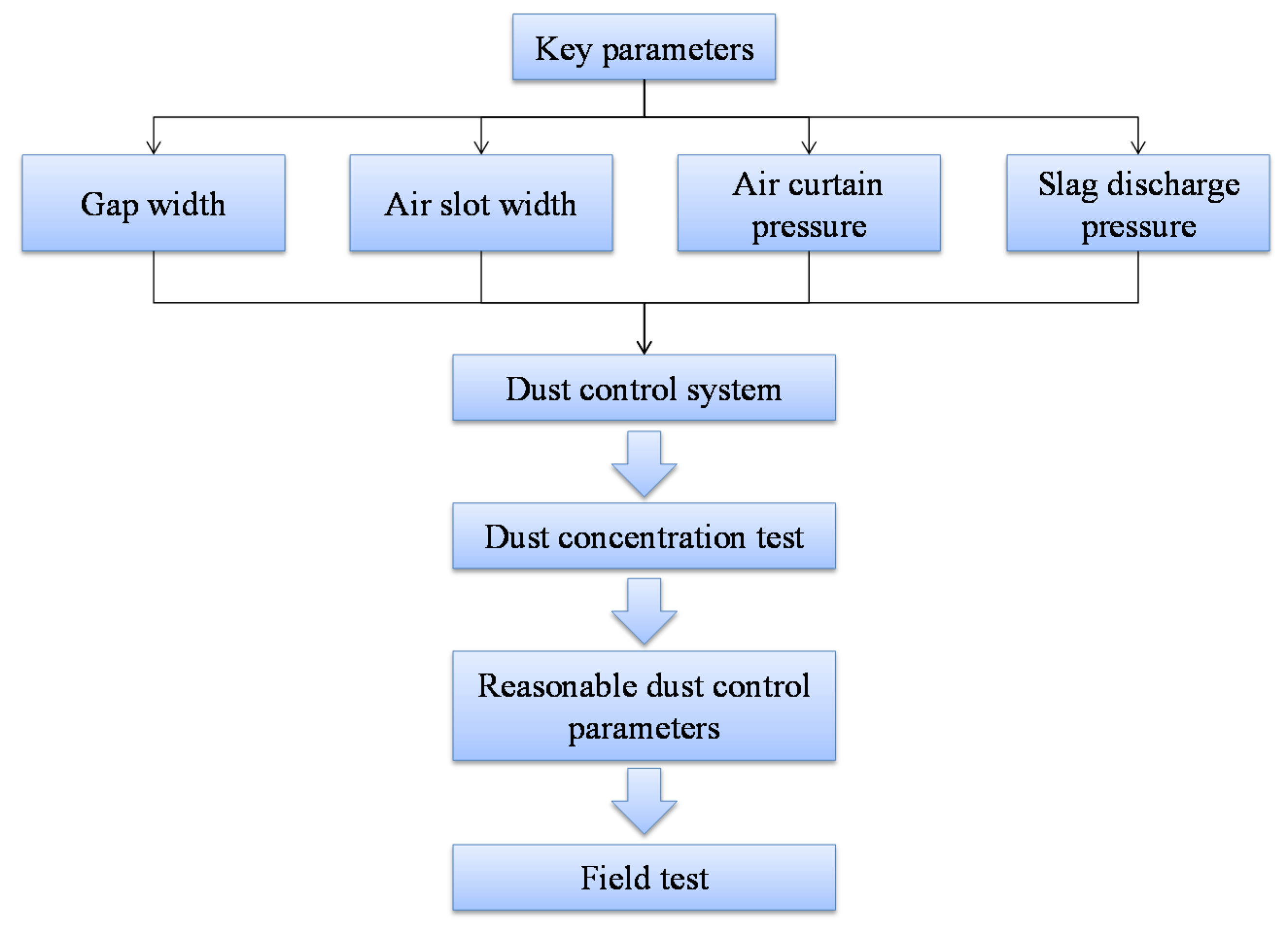
Four key parameters—namely, the gap width between the dust hood and the drill pipe (hereinafter referred to as “gap width”), the air-slot width of the sealing device (hereinafter referred to as “air-slot width”), the air curtain pressure, and the slag discharge pressure—mainly affect the dust control effect of the dust hood. For example, gap widths should not be too large, whereas air-slot widths should not be too small. Therefore, to obtain enough slag discharge pressure, it is necessary to optimize these parameters when designing dust hoods. The optimization process is shown in Figure 4.
3. Key Parameters of the Dust Control System
In this study, we designed a dust-hood testing system, which is explained in this section. By using this system, we obtained the optimal parameters of the dust hood and optimized the dust control system.
3.1. Testing System and Parameter Selection
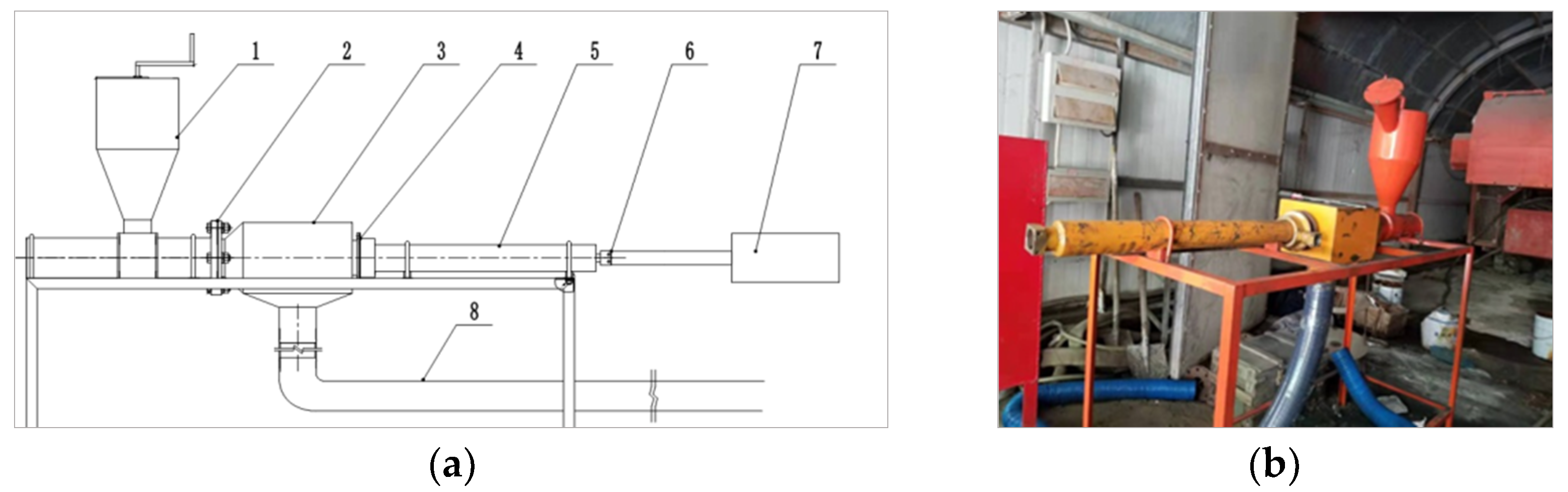
A special test platform (Figure 5) was designed to evaluate the effect of the parameters of the dust hood on dust control—namely, gap width, air-slot width, and air curtain pressure.
In this product, the outer diameter of the drill pipe is 75 mm, the inner diameter of the sealing pipe is 150 mm, and the dust output from the screw-driven dust-generating device is 6 kg/min. A negative pressure value of 1.5 kPa was added to the dust-collection pipe to simulate the negative pressure generated by the dry dust collector. Part of the air pressure of the air compressor was used for drilling, and the rest was used for slag discharge. Preliminary investigations and tests indicated that the slag discharge pressure was normally around 0.3 MPa, so the pressure in this testing system was set to this value accordingly. Under the above testing conditions, the parameters affecting dust control of the dust hood were examined. A dust concentration test was conducted according to the test method specified in GB 5748-85 “Method for Determination of Dust in the Air of Workplaces”, by choosing two monitoring points—one at the drill pipe and the other at a leeward point of 0.5 m from the air slot of the dust hood.
3.2. Influence of Gap Width on Dust Control
When the slag discharge pressure and the air curtain pressure were fixed, and the air-slot width was set to 0.2 mm, the gap width was adjusted to 0.5, 1.0, 1.5, 2.0, and 2.5 mm. The dust control effect is shown in Table 1.
Table 1 reveals that the gap width affected dust control—the smaller the gap, the better the dust control effect. When the gap width was 0.5 mm, the dust concentration was 27 mg/m3. Due to the vibration of the drilling pipe, it is difficult to ensure the coaxiality of the drill pipe and the dust hood. If the gap between the dust hood and the drill pipe is too small, wear occurs in the dust control device, which reduces the dust control effect. Therefore, a gap width of 2.0 mm was chosen for the next step.
3.3. Influence of Air-Slot Width on Dust Control
When the slag discharge pressure and the air curtain pressure were fixed, and the gap width was 2.0 mm, the dust control effect was tested when the air-slot width varied from 0.1 to 0.2, 0.3, 0.4, and 0.5 mm. The results are shown in Table 2.
Table 2 reveals that the wider the air slot, the better the dust control effect. When the air-slot width was 0.2 mm, dust concentration quickly dropped to 50 mg/m3, but when the air-slot width continued to increase, the dust control effect was not significantly improved.
3.4. Influence of Air Curtain Pressure on Dust Control
After the optimal gap width was set to 2.0 mm, and the air-slot width at 0.2 mm, the dust control effects under different slag discharge pressures and air curtain pressures were evaluated, respectively, the results of which are shown in Table 3, Table 4 and Table 5.
Table 3, Table 4 and Table 5 show that when the gap width and the air-slot width were fixed, the increase in air curtain pressure significantly improves the dust control effect; when the air curtain pressure was the same as the slag discharge pressure, the dust concentration stopped its abrupt drop and decreased slowly in an evidently good dust control region. When the slag discharge pressure was 0.3 MPa, and the air curtain pressure was 0.5 MPa, the dust control efficiency reached 97.2%.
4. Field Test of Dust Hood
We carried out a field test on the effect of dust hood in Qinlong Coal Mine, and field test results are discussed in this section, verifying the correctness of laboratory test results.
4.1. Field-Measured Conditions and Schemes
The experiment results showed that the best dust control effect was achieved when the gap width was 2 mm, the air-slot width was 0.2 mm, the slag discharge pressure was 0.3 MPa, and the air curtain pressure was 0.5 MPa. Therefore, the above parameters were selected for a field test near a stone gate of a mining area in Qinglong Coal Mine. A ZDY4000LD (C) directional drilling rig and a drill pipe with a diameter of 73 mm were used in the field test, and finally, a drilling hole with a diameter of 108 mm was obtained. Considering the fact that this mining area is mainly composed of an 18# coal seam with a thickness of 3.1 m, the on-site investigation revealed that the f coefficient of the coal seam was only about 0.57, indicating the coal seam was seriously broken, with loose cementation. During the drilling process, a large amount of slag and dust was generated; about 15 kg~30 kg of slag was produced after the 1.5 m drill pipe was drilled in at its full length. The original gas content in this 18# coal seam was high (11.8790~13.5790 m3/t). As the gas gushing out from the working face or after blasting mixes into the wind flow of the working face, to ensure the safety of the field test, drilling work started when the gas density was less than 1%, and the wind speed around the drilling site was not less than 0.25 m/s.
In the directional drilling operation, the air compressor for the air screw motor produced a nominal pressure of 1.25 MPa and a nominal flow of 17 m3/min. A compressed air pipeline was used to provide air pressure for the dust hood, with a maximum pressure of 0.5 MPa. During the test, the total pressure of the air compressor was 1.25 MPa, of which 0.3 MPa was used for slag discharge.
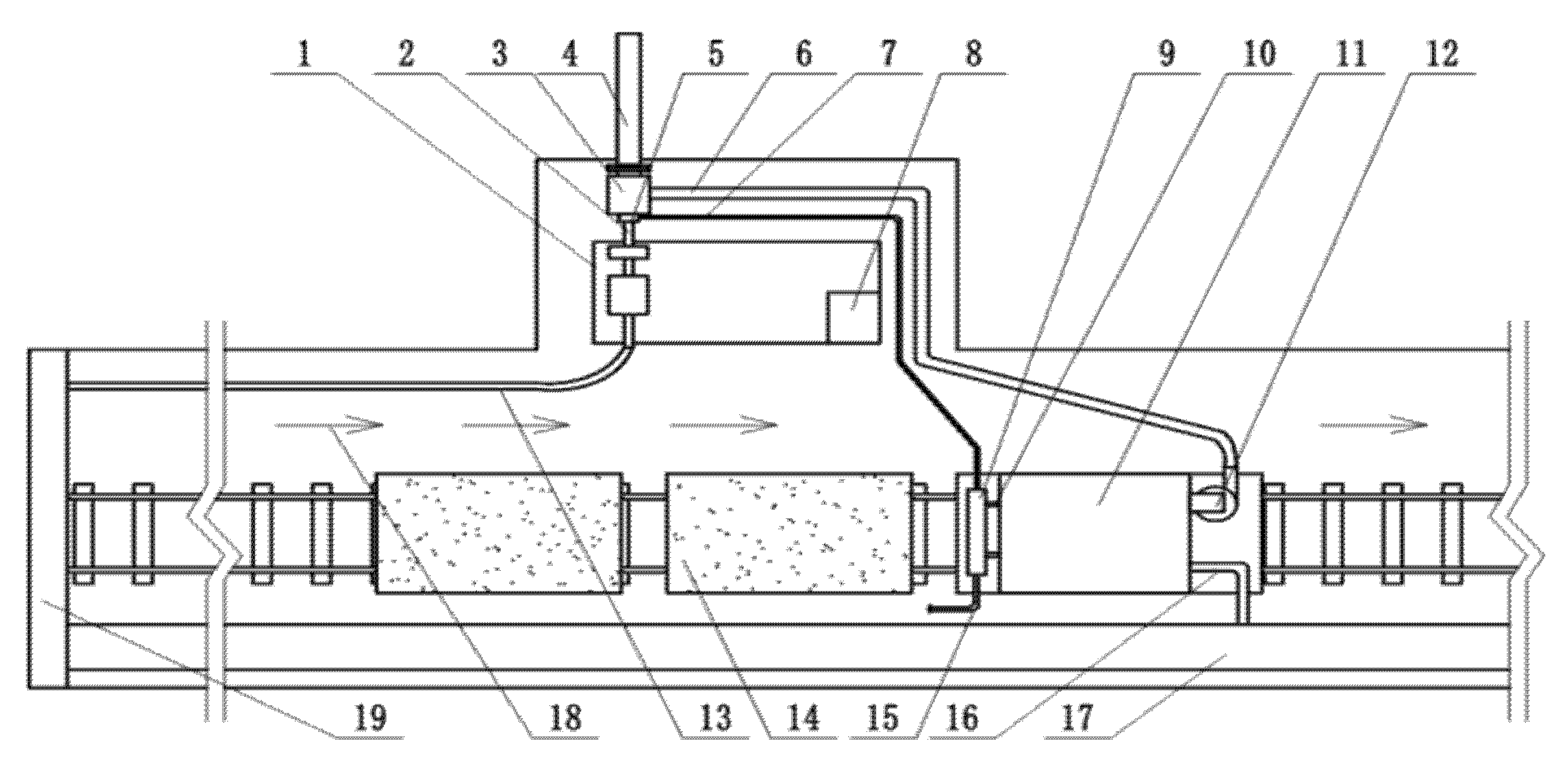
Two monitoring points were chosen—one at the drill pipe and the other at a leeward point 0.5 m from the air slot of the dust hood. The layout of the field equipment is shown in Figure 6.
4.2. Influence of Air Curtain Pressure on Dust Control
At the drilling depth of 20 m, the dust concentration was obtained (shown in Table 6) when the air curtain pressure changed to 0, 0.1, 0.2, 0.3, 0.4, and 0.5 MPa.
It can be seen from Table 6 that when the air curtain pressure was 0 MPa, the dust concentration at the two monitoring points reached 3907 mg/m3; after the dust control device was used, dust diffusion at the drilling hole was under certain control. When the air curtain pressure increased, dust concentration decreased further. When the air curtain pressure reached 0.5 MPa, the average dust concentration decreased to 67 mg/m3, and the dust control efficiency reached 98.3%.
4.3. Dust Control Effect under Different Drilling Depths
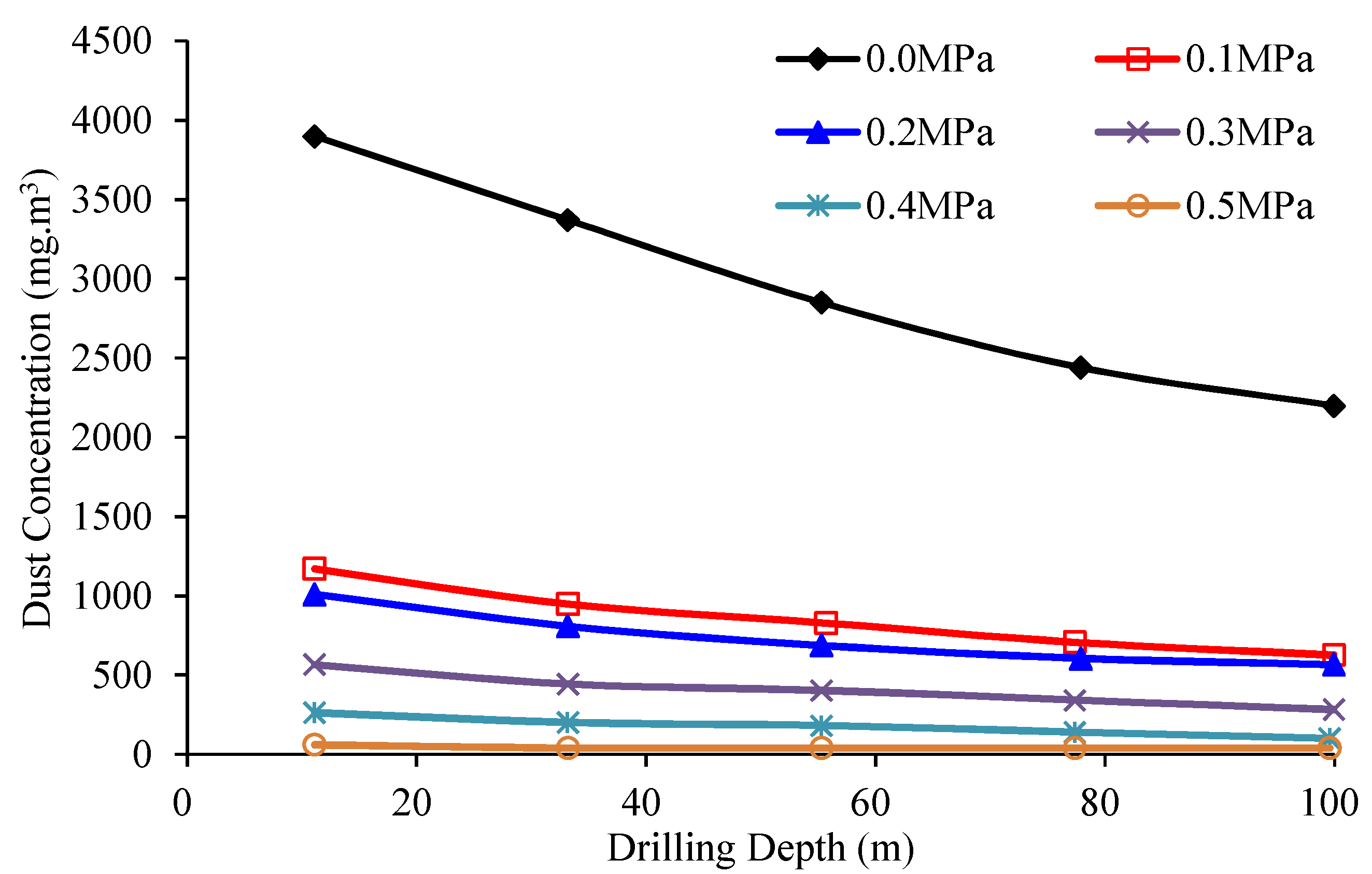
The dust control effects at drilling depths of 20, 40, 60, 80, and 100 m were investigated to obtain the dust concentration values at the two monitoring points. The results are shown in Figure 7.
Though dust concentration at the drilling hole decreased with the increase in the drilling depth (Figure 7), it stayed over 2000 mg/m3 when the dust control device was not used. After the dust control device was used, dust diffusion was well-controlled, and dust concentration at different drilling depths was considerably reduced.
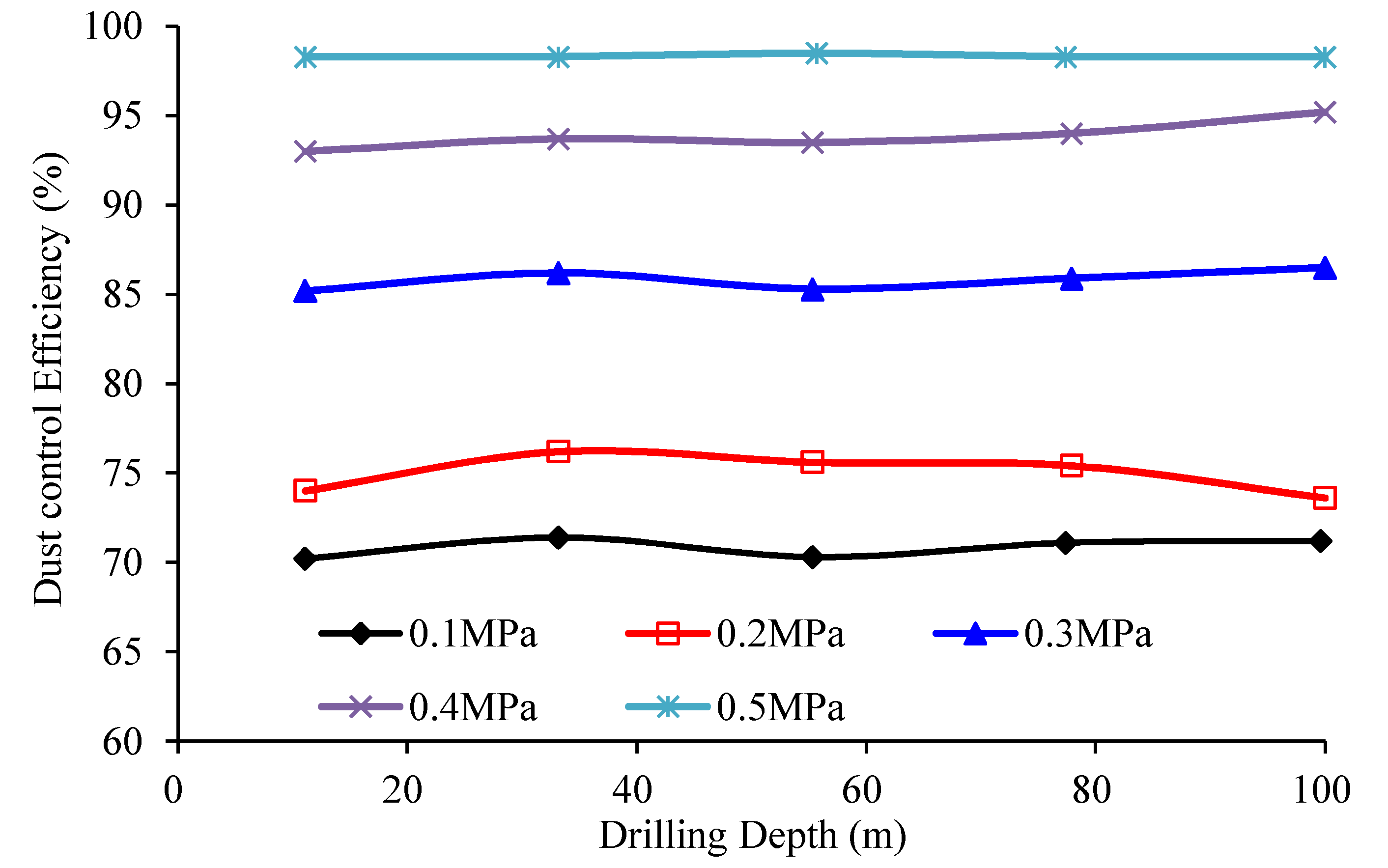
Using the test results of dust concentration at the two monitoring points, the dust control efficiency at different drilling depths was calculated (shown in Figure 8).
It can be seen from Figure 8 that air curtain pressure affects dust control efficiency. When the air curtain pressure increased from 0.1 MPa to 0.5 MPa, the dust control efficiency increases gradually with it. When the air curtain pressure was 0.5 MPa, the dust control efficiency at each drilling depth was above 95%, which means dust diffusion was well-controlled.
5. Conclusions, Limitations, and Future Research
(1) Through experimental research on key parameters of the dust hood, the influence of the gap width, air-slot width, and air curtain pressure on the dust control effect was obtained. The research results showed that when the gap width, air-slot width, slag discharge pressure, and air curtain pressure were at 2 mm, 0.2 mm, 0.3 MPa, and 0.5 MPa, respectively, dust concentration was reduced from 540 mg/m3 to 15 mg/m3, and dust control efficiency reached 97.2%.
(2) Field application of the dust hood showed that the dust diffusion resulting from drilling can be effectively controlled; when the air curtain pressure was 0.5 MPa, the dust control efficiency during the whole drilling process was above 95%.
(3) The dust hood can effectively control dust diffusion in dry directional drilling in SBCS. With the help of highly efficient dust collectors, the dust control system can significantly reduce dust concentration in the workplace and improve the operating environment of the drilling site.
The newly developed dust hood at drilling holes can avoid dust diffusion at the source. Its application will significantly improve the working environment of underground workers and protect their health. Nevertheless, the proposed dust hood can be further optimized. First, on the premise of high dust control efficiency, the amount of compressed air used by the dust control system should be further reduced to save energy. Second, a detachable dust hood should be designed to facilitate on-site use and improve work efficiency.
Author Contributions
Laboratory test and writing, D.W.; field investigation and editing, J.G.; writing—review and editing, K.L. All authors have read and agreed to the published version of the manuscript.
Funding
This research was supported by the National Natural Science Foundation of China (No. 51874281) and the Experimental Technology Research and Development Project of the China University of Mining and Technology (No. S2020D002).
Data Availability Statement
Not applicable.
Acknowledgments
The authors would like to thank Wei Qin, Yewen Dong, and Haidong Zhang for the field data measurements.
Conflicts of Interest
The authors declare no conflict of interest.
References
- Zhao, J. Key technology of large diameter directional borehole in hard rock of coal seam roof. China Energy Environ. Prot. 2020, 42, 139–143. [Google Scholar]
- Duan, H.; Hao, S.; Wang, Y. Application of Directional Drilling Technology and Equipment in Roof Large Diameter Long Hole. Coal Mine Mach. 2020, 41, 145–148. [Google Scholar]
- Liang, D.; Cao, J.; Dai, M. Progressive gas extraction technology in broken soft coal seam of Qinglong coal mine, Guizhou Province. Coal Geol. Explore. 2020, 48, 48–52. [Google Scholar]
- Xu, S.; Liu, F.; Liang, D. Application of comb type directional drilling in broken-soft coal seam floor for gas control. Drill. Eng. 2019, 46, 45–50. [Google Scholar]
- Gong, Q.; Wang, W.; Zhou, D. Application of directional long hole hydraulic fracturing technology in coal mine gas control. Coal Mine Mod. 2020, 6, 147–149. [Google Scholar]
- Tabacaru, V. Artificial neural networks applied to prediction of surface roughness in dry drilling of some polymers. In Proceedings of the 2020 IOP Conference Series: Materials Science and Engineering, Chennai, India, 23–27 June 2020; Volume 916, pp. 1–6. [Google Scholar]
- Li, H.; Ma, J. Analysis on gas drainage effect of large diameter roof directional long borehole instead of high drainage rock roadway. Coal Sci. Technol. 2020, 48, 304–310. [Google Scholar]
- Zhang, J.; Wang, Y.; Huang, H. Research on directional drilling technology of air screw motor in soft coal seam. Coal Sci. Technol. 2018, 46, 114–118. [Google Scholar]
- Yang, Y. Application of ground directional bedding drilling in grouting reconstruction of aquifer in mining face. Coal Mine Mod. 2020, 4, 185–187. [Google Scholar]
- Zhang, H.; Li, Y. Dust control of dry drilling operation in gas drainage drilling construction. Shandong Coal Sci. Technol. 2020, 6, 98–100. [Google Scholar]
- Shi, Y. Extraction technology and application of long directional boreholes along bedding. China Energy Environ. Prot. 2020, 42, 8–11. [Google Scholar]
- Guo, S. Development and application on pneumatic and wet type dust collector in mine. Coal Sci. Technol. 2012, 40, 74–78. [Google Scholar]
- Zhang, H. On the Law of Producing Dust and Control Dust Technology in Dry Drilling Coal Roadway. Master’s Thesis, Hunan University of Science and Technology, Xiangtan, China, 2017. [Google Scholar]
- Du, C.; Yang, Y. Exploration of Pneumatic Slagoff for Boreholes in Coal Seams. Coal Sci. Technol. Mag. 2007, 2, 57–59. [Google Scholar]
- Zheng, L.; Wang, C.; Qin, Y. Study of dust control based on analysis of dust distribution and diffusion in fully-mechanized face. Ind. Saf. Environ. Prot. 2007, 2, 57–59. [Google Scholar]
- Dang, K.; Joon, Y. Numerical investigation on the performance and flow pattern of two novel innovative designs of four-inlet cyclone separator. Chem. Eng. Process. 2020, 150, 87–93. [Google Scholar]
- Cheng, L.; Lu, Y.; Ge, Z. Design and Experimental Study of Gas-Solid Ejecting Dust Removal Apparatus Used in Coal Drilling. J. Basic Sci. Eng. 2015, 23, 1109–1119. [Google Scholar]
- Li, D.; Sui, J.; Liu, G. Technical status and development direction of coal mine dust hazard prevention and control technology in China. Min. Saf. Environ. Prot. 2019, 46, 1–7. [Google Scholar]
- Luo, Z.; Liu, R.; Cheng, F. Research status and development trend of coal dust explosion. Min. Saf. Environ. Prot. 2020, 47, 94–98. [Google Scholar]
- Chen, S.; Chen, J.; Li, G. Numerical simulation of dust concentration distribution regularities during dry drilling in coal seam. J. Harbin Inst. Technol. 2019, 51, 123–129. [Google Scholar]
- Wang, J.; Zhang, Y.; Su, H. Explosion characteristics and flame propagation behavior of mixed dust cloud of coal dust and oil shale dust. Energies 2019, 12, 3807. [Google Scholar] [CrossRef] [Green Version]
- Qi, Y.; Gan, X.; Li, Z. Variation and prediction methods of the explosion characteristic parameters of coal dust/gas mixtures. Energies 2021, 14, 264. [Google Scholar] [CrossRef]
- Dai, J. Study on Coal Dust Catching Technology and Mechanism Using Ultrasonic Atomization in Drilling. Master’s Thesis, China University of Mining and Technology, Xuzhou, China, 2008. [Google Scholar]
- You, W. Optimization design of dust-catching net in ultra-high mining height fully mechanized working face. Coal Mine Mach. 2021, 42, 11–14. [Google Scholar]
- Xie, Z.; Xiao, Y.; Jiang, C. Numerical research on airflow-dust migration behavior and optimal forced air duct installation position in a subway tunnel during drilling operation. Powder Technol. 2021, 388, 176–191. [Google Scholar] [CrossRef]
- Chen, L.; Liu, G. Airflow-dust migration law and control technology under the simultaneous operations of shotcreting and drilling in roadways. Arab. J. Sci. Eng. 2019, 44, 4961–4969. [Google Scholar] [CrossRef]
- Jiang, Z.; Wang, Y.; Men, L. Ventilation control of tunnel drilling dust based on numerical simulation. J. Cent. South Univ. 2021, 28, 1342–1356. [Google Scholar] [CrossRef]
- Liu, X.; Chang, P.; Wang, E. Numerical study of the respirable coal dust removal performance of a vortex ventilation system at an excavation face. Energies 2018, 11, 2449. [Google Scholar] [CrossRef] [Green Version]
- Chen, Y.; Zhang, X. Research and application on the new drilling dust collector. Coal Min. Saf. 2011, 42, 13–16. [Google Scholar]
- Guo, L.; Qin, G. Development of dry drilling dust collector. Non-Met. Mines 1999, 22, 40–41. [Google Scholar]
Figure 1.
Size distribution of coal-dust particles during dry drilling in Qinglong Coal Mine.

Figure 2.
Structure of the dust hood: (a) structure chart: 1—mounting flange of the dust hood; 2—cavity of the dust hood; 3—unidirectional sealing ring; 4—dust control device; 5—drill pipe; 6—compressed air interface; 7—dust hood outlet; 8—gap between the drill pipe and the dust hood; 9—air slot of the sealing device; (b) real product.

Figure 3.
Dust control system for directional drilling in SBCS: (a) structure chart. 1—pre-embedded extraction pipe; 2—dust hood; 3—drill pipe; 4—dry dust collector; 5—dust collection pipeline; 6—coal mass; 7—dust control system in drilling; (b) real product.
Figure 3.
Dust control system for directional drilling in SBCS: (a) structure chart. 1—pre-embedded extraction pipe; 2—dust hood; 3—drill pipe; 4—dry dust collector; 5—dust collection pipeline; 6—coal mass; 7—dust control system in drilling; (b) real product.

Figure 4.
Parameter optimization process of dust control system.

Figure 5.
Dust hood testing system: (a) cross-section of the product: 1—screw-driven dust-generating device; 2—sealing pipeline; 3—dust hood; 4—dust control device; 5—drill pipe; 6—KJ25 interface; 7—air compressor; 8—dust collection pipe; (b) real product.
Figure 5.
Dust hood testing system: (a) cross-section of the product: 1—screw-driven dust-generating device; 2—sealing pipeline; 3—dust hood; 4—dust control device; 5—drill pipe; 6—KJ25 interface; 7—air compressor; 8—dust collection pipe; (b) real product.

Figure 6.
Layout of field-test device: 1—directional drilling rig; 2—drill pipe; 3—dust hood; 4—sealing casing; 5—pressure air sealing device; 6—slag discharge pipe; 7—KJ25 rubber hose; 8—drill driver’s position; 9—air storage tank; 10—air supply pipe of ejector; 11—bag filter; 12—cyclone dust collector; 13—air supply pipe for screw motor; 14—mine car; 15—air supply pipe for dust collector; 16—connection pipe of drainage system; 17—gas drainage pipe; 18—airflow direction; 19—air damper.

Figure 7.
The dust concentration at different drilling depths.

Figure 8.
Dust control efficiency at different drilling depths.


Table 1.
The effect of gap width on dust control.
| Gap Width/mm | Slag Discharge Pressure/MPa | Slag Discharge Flow Rate/m3 min−1 | Air Curtain Pressure/MPa | Dust Concentration/ mg m−3 |
|---|---|---|---|---|
| 0.5 | 0.3 | 3.48 | 0.3 | 27 |
| 1.0 | 0.3 | 3.46 | 0.3 | 30 |
| 1.5 | 0.3 | 3.50 | 0.3 | 41 |
| 2.0 | 0.3 | 3.48 | 0.3 | 45 |
| 2.5 | 0.3 | 3.48 | 0.3 | 52 |
Table 2.
The effect of air-slot width on dust control.
| Air-Slot Width/mm | Slag Discharge Pressure/MPa | Slag Discharge Flow Rate/m3 min−1 | Air Curtain Pressure/MPa | Dust Concentration/ mg m−3 |
|---|---|---|---|---|
| 0.1 | 0.3 | 3.48 | 0.3 | 240 |
| 0.2 | 0.3 | 3.46 | 0.3 | 50 |
| 0.3 | 0.3 | 3.50 | 0.3 | 45 |
| 0.4 | 0.3 | 3.48 | 0.3 | 42 |
| 05 | 0.3 | 3.48 | 0.3 | 37 |
Table 3.
Dust control effect with the slag discharge pressure at 0.1 MPa.
| Air Curtain Pressure/MPa | Slag Discharge Pressure/MPa | Slag Discharge Flow Rate/m3 min−1 | Dust Concentration/ mg m−3 |
|---|---|---|---|
| 0.0 | 0.1 | 3.43 | 480 |
| 0.1 | 0.1 | 3.45 | 50 |
| 0.2 | 0.1 | 3.47 | 35 |
| 0.3 | 0.1 | 3.45 | 23 |
| 0.4 | 0.1 | 3.44 | 21 |
| 0.5 | 0.1 | 3.49 | 20 |
Table 4.
Dust control effect with the slag discharge pressure at 0.2 MPa.
| Air Curtain Pressure/MPa | Slag Discharge Pressure/MPa | Slag Discharge Flow Rate/m3 min−1 | Dust Concentration/ mg m−3 |
|---|---|---|---|
| 0.0 | 0.2 | 3.75 | 470 |
| 0.1 | 0.2 | 3.74 | 107 |
| 0.2 | 0.2 | 3.78 | 34 |
| 0.3 | 0.2 | 3.81 | 26 |
| 0.4 | 0.2 | 3.76 | 15 |
| 0.5 | 0.2 | 3.75 | 10 |
Table 5.
Dust control effect with the slag discharge pressure at 0.3 MPa.
| Air Curtain Pressure/MPa | Slag Discharge Pressure/MPa | Slag Discharge Flow Rate/m3 min−1 | Dust Concentration/ mg m−3 |
|---|---|---|---|
| 0.0 | 0.3 | 3.84 | 540 |
| 0.1 | 0.3 | 3.85 | 255 |
| 0.2 | 0.3 | 3.85 | 97 |
| 0.3 | 0.3 | 3.83 | 24 |
| 0.4 | 0.3 | 3.84 | 19 |
| 0.5 | 0.3 | 3.86 | 15 |
Table 6.
Results of dust-concentration field test.
| Air Curtain Pressure/MPa | Slag Discharge Pressure/MPa | Dust Concentration/mg m−3 |
|---|---|---|
| 0.0 | 0.3 | 3907 |
| 0.1 | 0.3 | 1168 |
| 0.2 | 0.3 | 1015 |
| 0.3 | 0.3 | 582 |
| 0.4 | 0.3 | 272 |
| 0.5 | 0.3 | 67 |
Publisher’s Note: MDPI stays neutral with regard to jurisdictional claims in published maps and institutional affiliations. |
© 2022 by the authors. Licensee MDPI, Basel, Switzerland. This article is an open access article distributed under the terms and conditions of the Creative Commons Attribution (CC BY) license (https://creativecommons.org/licenses/by/4.0/).
Share and Cite
MDPI and ACS Style
Wu, D.; Gao, J.; Lu, K. Dust Control Technology in Dry Directional Drilling in Soft and Broken Coal Seams. Energies 2022, 15, 3804. https://0-doi-org.brum.beds.ac.uk/10.3390/en15103804
AMA Style
Wu D, Gao J, Lu K. Dust Control Technology in Dry Directional Drilling in Soft and Broken Coal Seams. Energies. 2022; 15(10):3804. https://0-doi-org.brum.beds.ac.uk/10.3390/en15103804
Chicago/Turabian StyleWu, Dongmei, Jie Gao, and Ke Lu. 2022. "Dust Control Technology in Dry Directional Drilling in Soft and Broken Coal Seams" Energies 15, no. 10: 3804. https://0-doi-org.brum.beds.ac.uk/10.3390/en15103804
Note that from the first issue of 2016, this journal uses article numbers instead of page numbers. See further details here.