
Maximum Efficiency Conditions Satisfying Power Regulation Constraints in Multiple-Receivers Wireless Power Transfer


Department of Electrical Engineering, Incheon National University, Incheon 22012, Korea
*
Authors to whom correspondence should be addressed.
Energies 2022, 15(10), 3840; https://0-doi-org.brum.beds.ac.uk/10.3390/en15103840
Submission received: 25 March 2022
/
Revised: 10 May 2022
/
Accepted: 22 May 2022
/
Published: 23 May 2022
(This article belongs to the Special Issue Next Generation Wireless Charging System for Mobile Devices)
Abstract
:We propose the conditions for maximum overall efficiency at the constraint of satisfying asymmetric load power requirements for each receiver, for multiple-receivers wireless power transfer. Previously, the limitation of multiple-receiver analysis was that only the efficiency was maximized, whereas the requirements of load power were neglected. In many cases, conventional efficiency maximization assigns insufficient power to receivers far from the transmitter, while supplying excessive power to receivers near the transmitter. To resolve this limitation, we maximize the efficiency at the constraints of specified load power for each receiver. The proposed closed-form equation provides an optimum TX coil current amplitude, and the optimum load resistances of each receiver, to achieve the maximum efficiency at the load power regulation.
1. Introduction
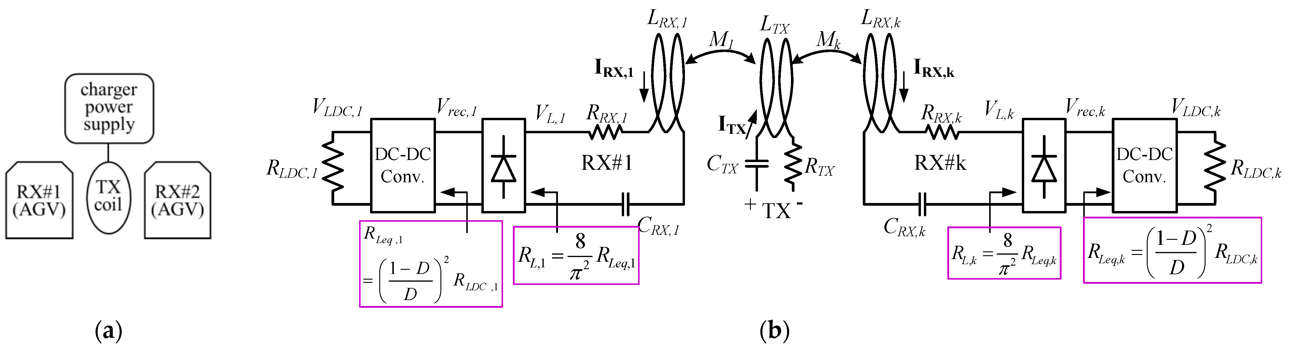
A multiple-receivers wireless power transfer system is promising because only one transmitter (TX) can be shared for multiple devices. Figure 1a illustrates such a scenario. Many prior papers have discussed the optimization with multiple receivers (RXs). Most of them pay attention to efficiency maximization [1,2,3,4,5]. Specifically, in [3,4,5], the load resistances of each RX was optimized to maximize overall system efficiency. Unfortunately, this enforces the power delivered to each RX to be proportional to the square of the coupling coefficients, i.e., P1:P2 = M12:M22, if the two RXs are identical. However, the amounts of power delivered to each RX must be the same with demanded power, which are determined by runtime power requirements such as battery charging status. Therefore, the efficiency should be maximized at a condition where an exact amount of power demanded by each RX is being delivered. In [6], these goals are addressed by exciting two different frequencies simultaneously. The two receivers were tuned at distinct frequencies, and the transmitter resonant frequency is adjusted in between the two distinct receiver frequencies. The authors of [7] focus on the power distribution to multiple receivers. They used n distinct frequencies for n receivers, and each receiver is tuned at different frequencies (100 kHz, 200 kHz, and 300 kHz) from each other in order to isolate the effect from another frequency channel. Because the power level at each frequency was adjusted, each receiver can achieve power regulation using a single TX. The authors of [8,9] designed a multiple receiver system at the viewpoint of coil geometry and magnetic field distribution. An analytic optimum RX load condition was not discussed. The authors of [10] propose a self-oscillating inverter for multiple receivers. This was to track the zero-voltage switching point of the TX inverter and to maintain a constant output power. In [11], the cross-coupling issue between multiple receivers is discussed. They discussed that the coupling between receivers causes additional reactance on receiver coils, while the resistance is unaffected. The effect of cross coupling can be compensated by adjusting the inductance or capacitance of the coil. A capacitance-adjusting circuit was demonstrated in [11] to compensate the additional reactance.
The authors of [12] propose an iterative algorithm that maximizes efficiency at the constraint of target delivered power for each RX. However, the algorithm requires ANSYS Maxwell simulation per each iteration trial. Hence, it was time-consuming and practical deployment was not possible.
Although many prior papers dealt with efficiency and power, none of them maximizes efficiency at the constraint of power regulation for each receiver. Previously, the maximum efficiency and the maximum power transfer were considered as separated targets because, in general, they cannot be achieved simultaneously. For example, refs. [3,4] derived one condition for the maximum efficiency, and the other condition for maximum load power. One of the key points of [3,4] was that the two conditions are distinct from each other. In other words, if the system was designed to achieve maximum efficiency conditions, then the power delivered to each receiver was enforced to undesired levels. More specifically, the maximum efficiency condition obtained in [3,4] is and where was a common factor for both receivers, and RRX,1 and RRX,2 were the parasitic resistance of RX,1 and RX,2, respectively. In other words, the maximum efficiency was obtained when RL1:RL2 = RRX,1:RRX,2. Unfortunately, at this condition, the ratio of power delivered to each receiver was . In other words, the power delivered to each receiver was enforced to be proportional to the square of coupling over parasitic resistance. This is problematic because the received power cannot be regulated among different receivers. In real-world applications, each receiver has a unique power demand, and this is not to be prescribed by coupling or parasitic resistances. For example, the battery charging power should be determined based on the battery capacity and the State of Charge. Therefore, the previous maximum efficiency condition is hard to be applied practically. Usually, the condition for maximum efficiency must be enforced once the different load powers are defined.
Another paper [13] maximizes the summation of power delivered to each receiver. The authors of [13] propose a multi-TX and multi-RX and this is applied to a capacitive wireless power system. The efficiency was not considered in [13]. Moreover, simply maximizing the summation of the power for each receiver is not the main issue in a practical scenario. Instead, each receiver should receive only a specified power depending on its runtime power demand status. For example, for a near-fully-charged battery, its charging power should be reduced to avoid damage of the battery and a possible battery explosion.
In summary, delivering an exact necessary power for each receiver is a precondition, and efficiency maximization should be sought with this precondition.
We propose an explicit closed-form equation to maximize efficiency at the constraint of delivering the exact amount of power demanded by each RX. The equation gives an optimum amplitude of TX coil current, |ITX|, and load resistances of each RX to satisfy both the efficiency and the power requirements. The proposed closed-form equation can easily be embedded in a low-cost microcontroller that are widely used in practical deployment.
2. Theoretical Derivations
2.1. Load Resistance Required for Power Demand Specification
The load resistance required to receive the exact amount of power is derived as a function of TX coil current. In order for the kth RX to receive the demanded power Pk, the relationship is:
where RL,k is the load impedance of kth RX, Mk is the coupling between TX and kth RX, and RRX,k is parasitic resistance, respectively. The IRX,k is expressed as . The RL,k which satisfies (1) is:
where the approximation in (2) is valid when is satisfied, which is true because a typical wireless charging system is designed with a small value of parasitic resistance RRX,k for a high efficiency. It is observed that the RL,k that is required to receive the exact amount of specified power Pk depends on the rms amplitude of TX coil current.
Even if the end-user DC load resistance RLDC,k cannot be changed, the RLeq,k can be runtime adjusted by controlling the duty cycle of the DC–DC converter [14,16,17,18,19]. For a buck–boost converter, the transformation of holds where D is the duty cycle of the DC–DC converter [14]. Moreover, the RL,k = 8/π2∗RLeq,k relationship is valid for a full-bridge rectifier. As a result, the effective load resistance presented to the RX coil, RL,k, can be runtime transformed from a given RLDC,k.
Changing the |ITX| changes VL,k and Vrec,k. Now, the DC–DC converter has its own voltage regulation loop internally—its output voltage, VLDC,k, is regulated according to the end-user load voltage demand (commonly fixed voltages such as 24 V, 48 V, etc.). Therefore, changing the |ITX| also changes the duty cycle of the DC–DC converter. This transforms the given RLDC,k into an effective RL,k seen by the RX coil. The end-user load VLDC,k and RLDC,k remain constant regardless of the system control such as |ITX| and duty cycle. The actual resistance that the RX coil sees is RL,k, not RLDC,k.
2.2. TX Coil Current to Maximize Efficiency with Specified Power Constraints
Overall power efficiency with n receivers is expressed as:
Conventional approaches of maximizing efficiency in [4,5] were to substitute (1) into (3), thereby canceling the |ITX| quantity both in the numerator and denominator of (3). This reduced to an equation that was expressed solely as a function of coupling and resistances. However, the resultant condition caused excessive power for strongly-coupled RX while power shortage for weakly-coupled RX. Thus, the RX could not achieve power regulation. To resolve the drawback, this paper substitutes (2) into (3), yielding
where the approximation is due to the approximation in (2). The (4) is the efficiency with the constraint of delivered power Pk for the kth receiver. Using Taylor series expansion, (4) is modified as:
Rearranging the denominator of (5) with respect to |ITX| yields,
where A = and B = . The Pk, RTX, A, and B are regarded as constant with respect to |ITX|. The maximum efficiency can be obtained by differentiating the denominator of (6) with respect to |ITX| and setting the result to zero. The optimum |ITX| that maximizes (6) is
where . While the optimum TX current is specified as (7), the optimum load resistances that maximize efficiency and satisfy the demanded power constraint are
The (7) and (8) are the proposed conditions for maximum overall efficiency while satisfying the load power requirement. The derivations for the (7) and (8) have used (1) and (2), which is the condition to satisfy the demanded power for each individual receiver.
The (8) can be achieved by setting |ITX,opt|. As discussed in Section 2.1 and Figure 1b, the |ITX,opt| sets Vrec,k, which in turn sets the duty cycle and finally the RL,k,opt. In this way, the RL,k (the resistance seen by RX coil) can have a different value from the end-user load resistance RLDC,k, and this can maximize the efficiency at the constraint of load power satisfaction.
The proposed theory is valid for any load voltages and currents because it is a function of the multiplication of voltage and current on the load, as seen in (7) and (8). This is another advantage of the proposed theory compared to conventional efficiency maximization conditions.
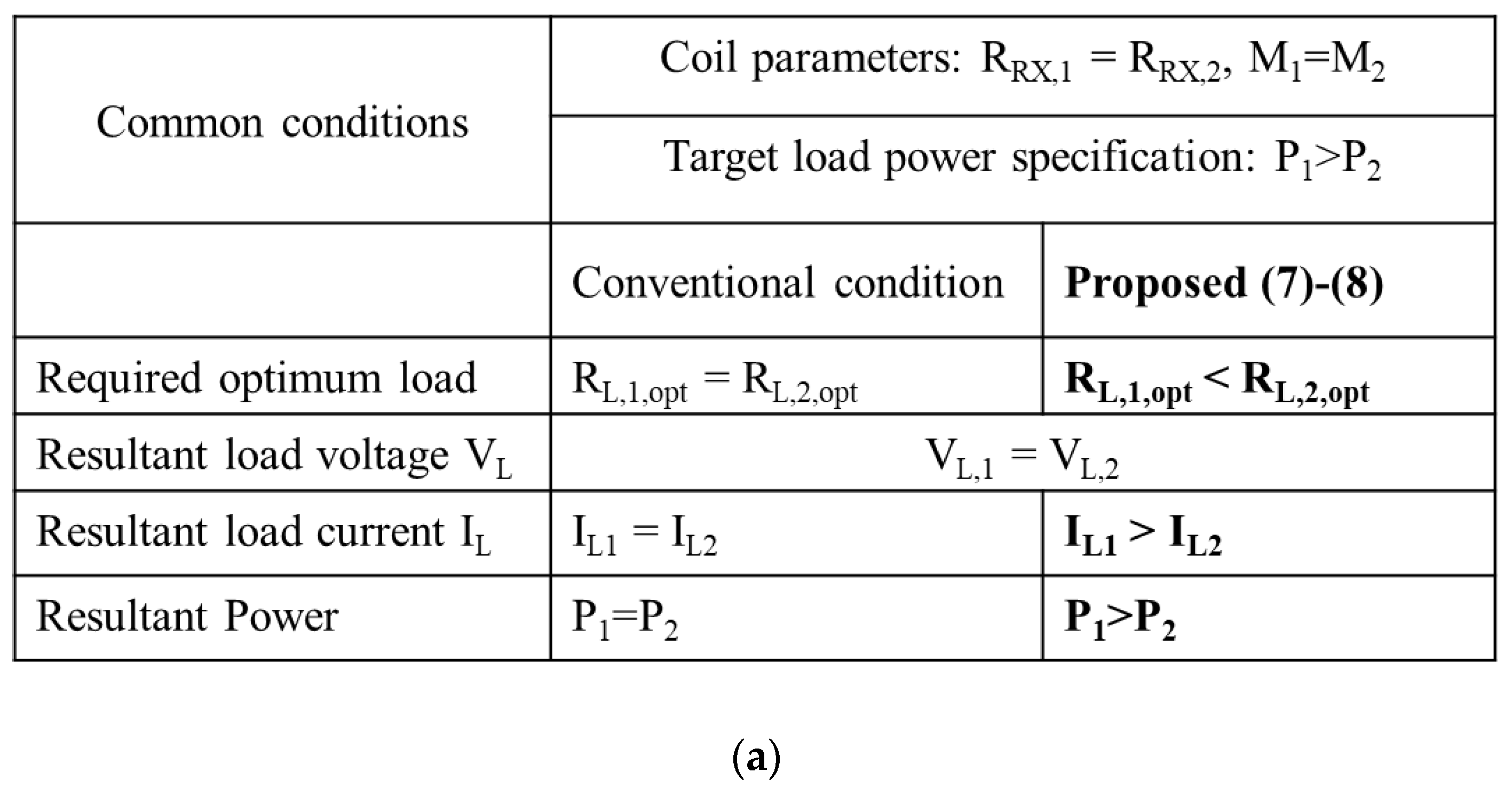
In conventional conditions, an optimum condition was specified as and where was a shared parameter for both RXs, which requires that the load resistance of RX,1 must have a fixed relationship with the load of RX,2. In other words, the freedom of choosing the load current for each RX is lost. Figure 2 illustrates this point. Take a scenario where RRX,1 = RRX,2 and M1 = M2 but the required load power of P1 > P2 as an example. The conventional condition gives RL1,opt = RL2,opt for maximum efficiency. However, because the voltage induced at each load VL,k is also identical to each other (due to M1 = M2), the load current IL for both RXs also becomes identical, which does not satisfy the P1 > P2 requirement. To satisfy P1 > P2 at the identical load voltages, the load current of RX1 should be increased, which necessitates the reduction of RL1, which in turn violates the RL1,opt = RL2,opt condition given by [3,4].
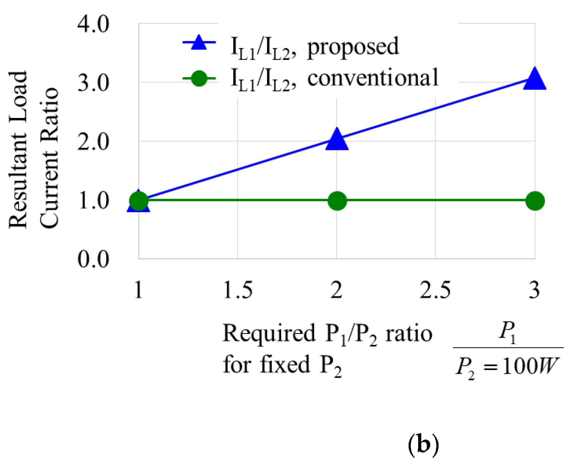
However, in the proposed theory, the (7) and (8) are derived such that they always satisfy the load power requirement Pk for each receiver. For the same scenario of RRX,1 = RRX,2 and M1 = M2 but the required load power of P1 > P2 as the example above, the proposed (7) and (8) give RL1,opt < RL2,opt for maximum efficiency. This allows a higher load current on RX,1 and can satisfy the P1 > P2 even if the induced load voltages are identical for both RXs. The (7) and (8) are a function of Pk, which is the multiplication of load voltage and current, not a function of individual load voltage or current. Therefore, the (7) and (8) are usable for any load voltage and current.
3. Results
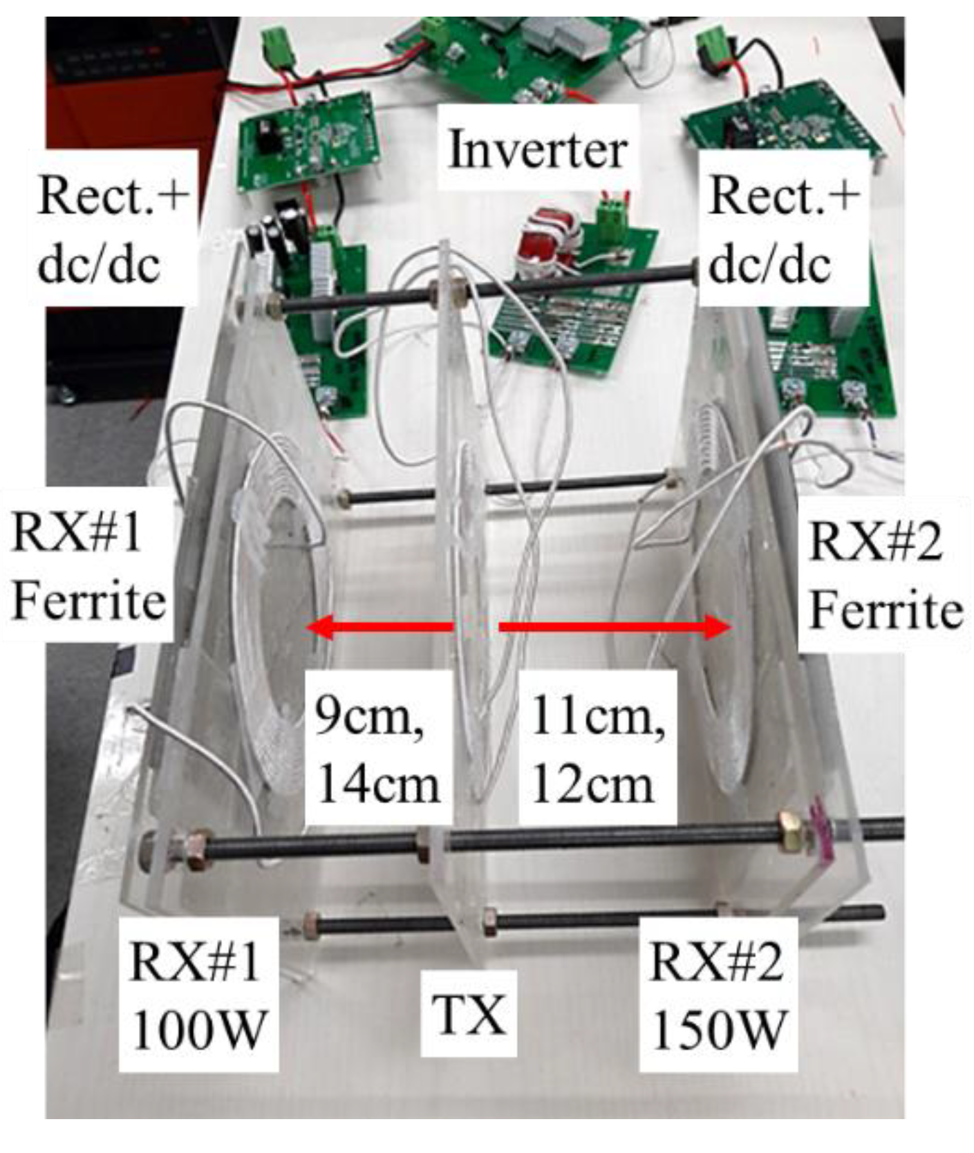
The target application is the simultaneous charging of two AGVs using one TX coil, as seen in Figure 3. This saves the number of transmitter hardware. The two RXs are on opposite sides to each other, while the TX is inserted in between the two RXs. In this experiment setup, the coupling between receivers is negligible because the two receivers are located on opposite sides of the TX to each other. As discussed in [11], if some coupling between receivers exists, its effect would be eliminated by adjusting the variable capacitor of the LC tank. The conditions for load resistance are not affected if the resonant capacitor is properly adjusted.
Each receiver contains a typical passive AC/DC rectifier and a buck–boost converter. The AC/DC rectifier is not involved in the maximum efficiency control or in the power regulation control. The passive rectifier just relays the input impedance of the DC–DC converter, RLeq,k, into the RX coil with a multiplication of 8/π2 scaling factor that inevitably happens during the AC/DC rectification. Changing the |ITX| also changes the duty cycle of the DC–DC converter because its VLDC,k should be fixed. This transforms the RLDC,k into RLeq,k. The RLeq,k is presented to the RX coil with the multiplication of 8/π2. Details are discussed in Figure 1b and Section 2. The output voltage of the DC–DC converter for RX#1 and RX#2 is 48 V and 25 V, respectively, whereas the load power for RX#1 and RX#2 have a different setting for each curve of Figure 4 by varying the load current.
Table 1 provides component parameters. Specifically, the two RXs have different distances from a TX, which usually happens in a practical scenario. In this paper, the P1:P2 = M12:M22 restriction is not necessary to maximize the efficiency. For example, Figure 4a red trace illustrates P1 = 100 W and P2 = 125 W while M1:M2 = 4.2:2.8 μH. An LCC resonant inverter generates an 85 kHz ITX current that can be controlled by DC voltage adjustment. The LRX-CRX of each receiver is tuned at 85 kHz. The output of the receiver is fed to a DC electronics load. The litz wire is a 0.06 mm/1000 strand. The ferrite material at the receiver is PM12 from Toda Isu.
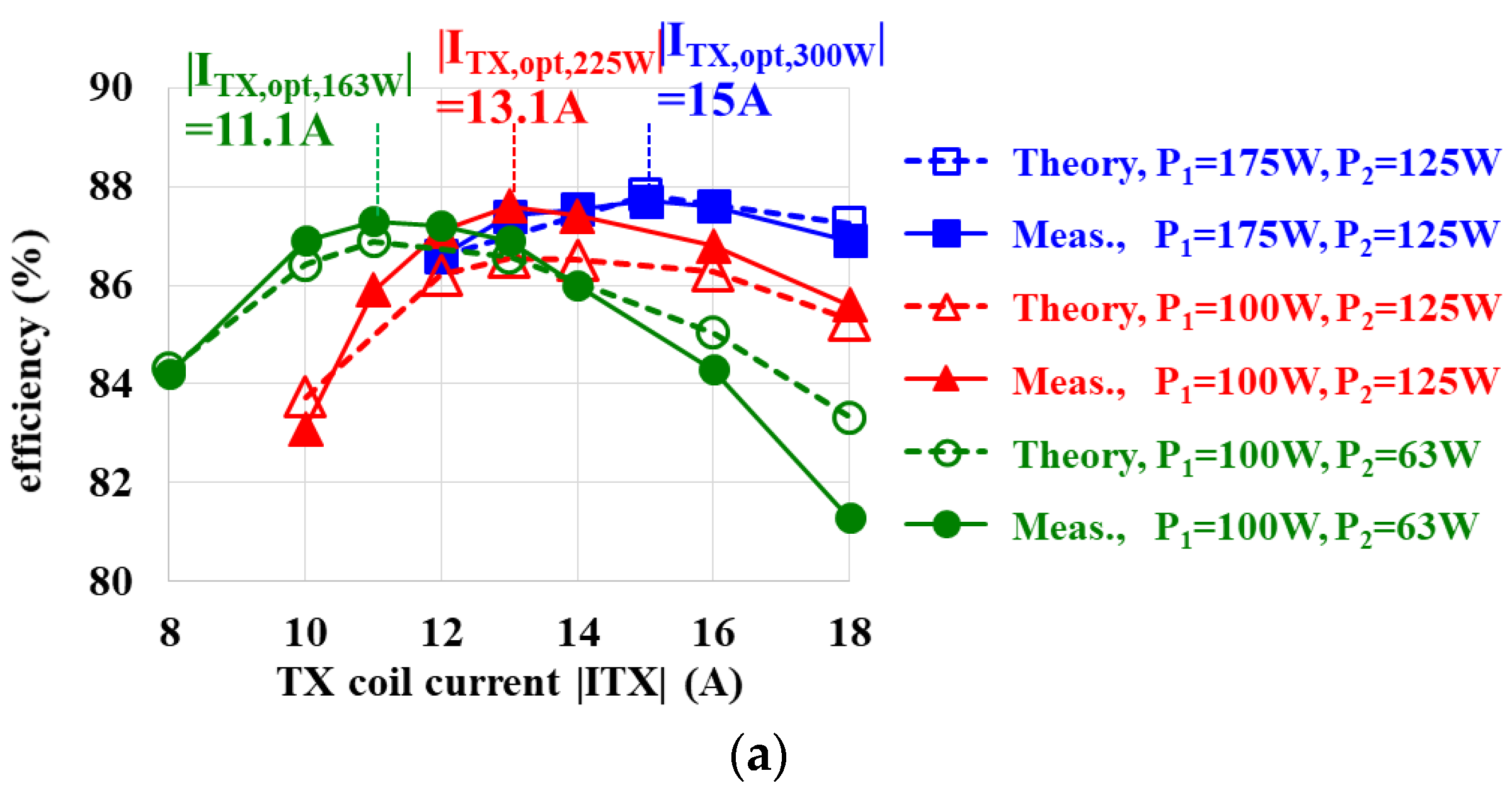
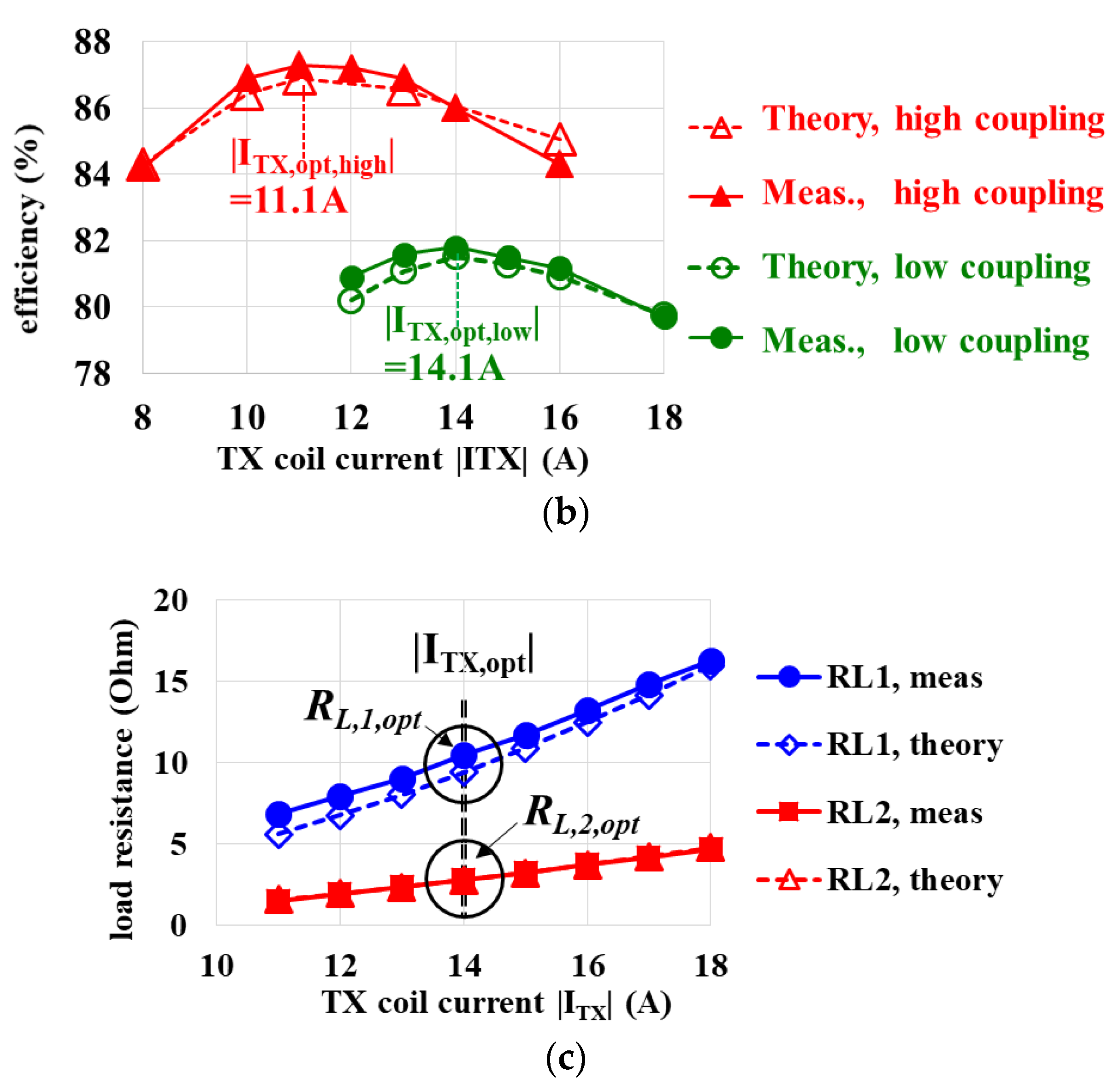
Figure 4a shows efficiency vs. |ITX| with different load power settings for a given coupling. The measured efficiencies are indeed maximized at the calculated |ITX,opt|, which are obtained by (7). Figure 4b shows efficiencies for variations of coupling. The theoretical optimum |ITX,opt| coincides with the measurement for each coupling condition. Figure 4c shows that the measured RL,1,opt = 10.5 Ω and the calculated RL,1,opt = 9.4 Ω agree well each other. The measured and the calculated RL,2,opt are both 2.8 Ω.
4. Conclusions
The work resolves the limitation of conventional optimization where the ratio of received power between each RX was proportional to the square of mutual inductance, i.e., P1:P2 = M12: M22 if two RXs were identical. This limitation was not acceptable because practical receivers demand power based on its battery-charging status, not based on mutual inductance with TX.
Therefore, this paper derives closed-form equations for optimum TX current and RX load resistance. The aim is to maximize efficiency at the constraint of specified load power for each receiver at any mutual inductances. The proposed (7) and (8) agree well with measurement.
Author Contributions
Conceptualization, D.A.; methodology, W.L. (Won Lee); validation, W.L. (Won Lee), W.L. (Woochan Lee); formal analysis, W.L. (Won Lee); investigation, W.L. (Woochan Lee); resources, W.L. (Woochan Lee); data curation, W.L. (Won Lee); writing—original draft preparation, W.L. (Won Lee); writing—review and editing, D.A., W.L. (Woochan Lee); supervision, D.A.; funding acquisition, D.A. All authors have read and agreed to the published version of the manuscript.
Funding
This work was supported by Incheon National University (2019-0186).
Data Availability Statement
Not applicable.
Conflicts of Interest
The authors declare no conflict of interest.
References
- Ahn, D.; Hong, S. Effect of Coupling Between Multiple Transmitters or Multiple Receivers on Wireless Power Transfer. IEEE Trans. Ind. Electron. 2012, 60, 2602–2613. [Google Scholar] [CrossRef]
- Kim, J.; Kim, D.-H.; Park, Y.-J. Free-Positioning Wireless Power Transfer to Multiple Devices Using a Planar Transmitting Coil and Switchable Impedance Matching Networks. IEEE Trans. Microw. Theory Tech. 2016, 64, 3714–3722. [Google Scholar] [CrossRef]
- Monti, G.; Che, W.; Wang, Q.; Costanzo, A.; Dionigi, M.; Mastri, F.; Mongiardo, M.; Perfetti, R.; Tarricone, L.; Chang, Y. Wireless Power Transfer With Three-Ports Networks: Optimal Analytical Solutions. IEEE Trans. Circuits Syst. I Regul. Pap. 2016, 64, 494–503. [Google Scholar] [CrossRef]
- Fu, M.; Zhang, T.; Ma, C.; Zhu, X. Efficiency and Optimal Loads Analysis for Multiple-Receiver Wireless Power Transfer Systems. IEEE Trans. Microw. Theory Tech. 2015, 63, 801–812. [Google Scholar] [CrossRef]
- Mongiardo, M.; Wang, Q.; Che, W.; Dionigi, M.; Perfetti, R.; Chang, Y.; Monti, G. Wireless Power Transfer between One Transmitter and Two Receivers: Optimal Analytical Solution. In Proceedings of the Asia-Pacific Microwave Conference (APMC), Nanjing, China, 6–9 December 2015; pp. 1–3. [Google Scholar] [CrossRef]
- Yang, Y.; Ding, Z.; Liu, F.; Chen, X. A Double-Frequency Superposition Methodology for High Efficiency and Oriented Power Distribution of MCR WPT System with Two Receivers. In Proceedings of the Energy Conversion Congress and Exposition (ECCE), Cincinnati, OH, USA, 1–5 October 2017; pp. 1–6. [Google Scholar] [CrossRef]
- Qi, C.; Huang, S.; Chen, X.; Wang, P. Multifrequency Modulation to Achieve an Individual and Continuous Power Distribution for Simultaneous MR-WPT System With an Inverter. IEEE Trans. Power Electron. 2021, 36, 12440–12455. [Google Scholar] [CrossRef]
- Li, J.; Qin, R.; Sun, J.; Costinett, D. Systematic Design of a 100-W 6.78-MHz Wireless Charging Station Covering Multiple Devices and a Large Charging Area. IEEE Trans. Power Electron. 2021, 37, 4877–4889. [Google Scholar] [CrossRef]
- Lee, E.S.; Kim, M.Y.; Kang, S.M.; Han, S.H. Segmented IPT Coil Design for Continuous Multiple Charging of an Electrified Monorail System. IEEE Trans. Power Electron. 2021, 37, 3636–3649. [Google Scholar] [CrossRef]
- Sun, S.; Zhang, B.; Rong, C.; Shu, X.; Wei, Z. A Multireceiver Wireless Power Transfer System Using Self-Oscillating Source Composed of Zero-Voltage Switching Full-Bridge Inverter. IEEE Trans. Ind. Electron. 2021, 69, 2885–2895. [Google Scholar] [CrossRef]
- Ishihara, M.; Fujiki, K.; Umetani, K.; Hiraki, E. Autonomous System Concept of Multiple-Receiver Inductive Coupling Wireless Power Transfer for Output Power Stabilization against Cross-Interference Among Receivers and Resonance Frequency Tolerance. IEEE Trans. Ind. Appl. 2021, 57, 3898–3910. [Google Scholar] [CrossRef]
- Lee, S.B.; Kim, M.; Jang, I.G. Determination of the Optimal Resonant Condition for Multireceiver Wireless Power Transfer Systems Considering the Transfer Efficiency and Different Rated Powers with Altered Coupling Effects. IEEE J. Emerg. Sel. Top. Power Electron. 2020, 9, 2384–2393. [Google Scholar] [CrossRef]
- Minnaert, B.; Monti, G.; Mastri, F.; Costanzo, A.; Mongiardo, M. Power maximization for a multiple–input and multiple-output wireless power transfer system described by the admittance matrix. In Proceedings of the 2020 XXXIIIrd General Assembly and Scientific Symposium of the International Union of Radio Science, Rome, Italy, 29 August–5 September 2020; pp. 1–4. [Google Scholar] [CrossRef]
- Zhong, W.; Hui, S.Y.R. Maximum Energy Efficiency Tracking for Wireless Power Transfer Systems. IEEE Trans. Power Electron. 2014, 30, 4025–4034. [Google Scholar] [CrossRef] [Green Version]
- Erickson, R.; Maksimovic, D. Fundamentals of Power Electronics; Kluwer Academic Publishers: New York, NY, USA, 2004. [Google Scholar]
- Dai, X.; Li, X.; Li, Y.; Hu, A.P. Maximum Efficiency Tracking for Wireless Power Transfer Systems with Dynamic Coupling Coefficient Estimation. IEEE Trans. Power Electron. 2017, 33, 5005–5015. [Google Scholar] [CrossRef]
- Yeo, T.-D.; Kwon, D.; Khang, S.-T.; Yu, J.-W. Design of Maximum Efficiency Tracking Control Scheme for Closed-Loop Wireless Power Charging System Employing Series Resonant Tank. IEEE Trans. Power Electron. 2016, 32, 471–478. [Google Scholar] [CrossRef]
- Kim, D.-H.; Kim, S.; Kim, S.-W.; Moon, J.; Cho, I.-K.; Ahn, D. Coupling Extraction and Maximum Efficiency Tracking for Multiple Concurrent Transmitters in Dynamic Wireless Charging. IEEE Trans. Power Electron. 2019, 35, 7853–7862. [Google Scholar] [CrossRef]
- Huang, Z.; Wong, S.-C.; Tse, C. Control Design for Optimizing Efficiency in Inductive Power Transfer Systems. IEEE Trans. Power Electron. 2017, 33, 4523–4534. [Google Scholar] [CrossRef]
Figure 1.
Wireless charging of multiple automatic guided vehicle (AGV), simultaneously. (a) Top view. One TX coil is in between two RXs and charges the two RXs simultaneously. (b) Equivalent circuit. The RLDC,k is the end-user DC load. The RLeq,k is the effective resistance transformed from RLDC,k. The RL,k = 8/π2∗RLeq,k is the resistance that the RX coil actually sees [14,15]. The AC/DC rectifier is not related to control.

Figure 2.
Comparison between conventional condition and proposed condition for maximum efficiency with target power constraints. The proposed method has freedom to choose load current to satisfy the asymmetric power requirement for each receiver. (a) Example scenario. (b) Resultant load current ratio with respect to the required power ratio.


Figure 3.
Experiment setup. The two RXs have different coupling from each other. The power requirement for each RX is asymmetric and is not restricted by coupling, unlike previous work.
Figure 3.
Experiment setup. The two RXs have different coupling from each other. The power requirement for each RX is asymmetric and is not restricted by coupling, unlike previous work.

Figure 4.
|ITX| sweeps while load power is regulated to required level. Theory agrees well with measurement. (a) The calculated optimum |ITX,opt| of (7) coincide with the measured |ITX| across different load powers. For constant M1 = 4.23 μH and M2 = 2.87 μH. (b) The calculated optimum |ITX,opt| of (7) coincide with the measured |ITX|. High coupling: M1 = 4.23 μH and M2 = 2.87 μH. Low coupling: M1 = 1.86 μH and M2 = 2.42 μH. P1 = 100 W and P2 = 63 W. (c) Load resistance for P1 = 100 W and P2 = 150 W. The theoretic RL,k,opt using (8) agree well with measurement.


Table 1.
System parameters.
| LTX | 30.4 μH | ||
| RTX CTX | 62.8 mΩ 154 nF | ||
| Frequency | 85 kHz | ||
| RX #1 | RX #2 | ||
| LRX1 | 35.4 μH | LRX2 | 38.96 μH |
| CRX1 | 98.7 nF | CRX2 | 89.6 nF |
| RRX1 | 0.29 Ω | RRX2 | 0.15 Ω |
| M1 | 4.2 μH/1.8 μH | M2 | 2.8 μH/2.4 μH |
Publisher’s Note: MDPI stays neutral with regard to jurisdictional claims in published maps and institutional affiliations. |
© 2022 by the authors. Licensee MDPI, Basel, Switzerland. This article is an open access article distributed under the terms and conditions of the Creative Commons Attribution (CC BY) license (https://creativecommons.org/licenses/by/4.0/).
Share and Cite
MDPI and ACS Style
Lee, W.; Lee, W.; Ahn, D. Maximum Efficiency Conditions Satisfying Power Regulation Constraints in Multiple-Receivers Wireless Power Transfer. Energies 2022, 15, 3840. https://0-doi-org.brum.beds.ac.uk/10.3390/en15103840
AMA Style
Lee W, Lee W, Ahn D. Maximum Efficiency Conditions Satisfying Power Regulation Constraints in Multiple-Receivers Wireless Power Transfer. Energies. 2022; 15(10):3840. https://0-doi-org.brum.beds.ac.uk/10.3390/en15103840
Chicago/Turabian StyleLee, Won, Woochan Lee, and Dukju Ahn. 2022. "Maximum Efficiency Conditions Satisfying Power Regulation Constraints in Multiple-Receivers Wireless Power Transfer" Energies 15, no. 10: 3840. https://0-doi-org.brum.beds.ac.uk/10.3390/en15103840
Note that from the first issue of 2016, this journal uses article numbers instead of page numbers. See further details here.