Article

Study on the Thermomechanical Response of Deep Buried Pipe Energy Piles under Temperature Load

1
School of Civil Engineering, Hubei University of Technology, Wuhan 430068, China
2
CCCC Second Highway Consultant Co., Ltd., Wuhan 430056, China
*
Author to whom correspondence should be addressed.
Submission received: 21 March 2022 / Revised: 12 May 2022 / Accepted: 21 May 2022 / Published: 23 May 2022

Abstract

:
A deep buried pipe energy pile (DBP-EP) is a composite structure that integrates ground-source heat pump (GSHP) systems and inside buried pipe energy piles (IBP-EP) to effectively achieve the improvement of heat transfer efficiency and quantity. Utilizing this technology in building a pile foundation can contribute to reducing carbon emissions. This paper studies the variation rules of the thermomechanical response of DBP-EP under temperature load via field testing and numerical simulation. The results show that, under heating and cooling conditions, the DBP-EP temperature variation within the pile is substantial, while there is no significant change in the temperature field at the bottom of the pile. This is different from the internal temperature change of the temperature distribution of IBP-EP. The minimum axial average strain of the DBP-EP under the cooling condition is significantly smaller than that under the heating condition. However, the additional axial average strain under the temperature load is significantly larger than that in the heating condition, resulting in larger additional axial stress when the pile is cooled. The connection between the pile and foundation must considered in design due to the large settlement of the pile top under cooling conditions. When only under the temperature load, the maximum axial average pressure increments of the pile in our test during heating and cooling are −85.3 kN/°C and 99.4 kN/°C, respectively, suggesting that the additional load cannot be ignored.

1. Introduction

Energy pile technology is a method of turning the pile foundation of a building into part of a ground source heat pump (GSHP) system by burying a heat-exchange pipe in the pile foundation and using the pile as a heat-exchange well. The heat transfer between the energy pile and the surrounding rock and soil is realized through the circulation of the fluid in the heat-exchange pipe. This is a novel geothermal extraction technology. The energy pile can both transfer heat as a GSHP system and improve the bearing capacity as the pile foundation under the upper load. In this way, it can eliminate the well drilling and grouting backfill section of GSHP systems, and solves the problem of large area [1,2]. However, constrained by the pile length of the building pile foundation, the heat-transfer range of the energy pile heat-exchange pipe in the pile foundation is limited [3,4]. We can set a deep heat transfer to obtain a better heat-exchange effect. At the same time, the DBP-EP enables the heat-exchange pipe to pass through the pile end to achieve an ideal depth for heat transfer. Furthermore, the deep buried pipe energy pile (DBP-EP) has a more flexible structure that the design of the pile body, and the relevant size of the deep well can be achieved according to the heat-transfer demand in practical applications, which is a further optimization of the inside buried pipe energy pile (IBP-EP) and the GSHP in the pile [5,6]. Furthermore, this realizes the efficient and economic utilization of geothermal resources as an efficient and feasible idea for the development of low-carbon buildings.
In recent years, scholars have carried out significant theoretical analyses, field tests and numerical simulations on the thermodynamic response of the heat-transfer process of the energy pile. Gui and Cheng et al. [7,8,9] further proved that the pile foundation heat exchangers have good heat-transfer performance through the comparative analysis of in situ tests and numerical simulation results of test piles. They analyzed the influence of cement hydration heat, heating power, pile group effect and other factors on the heat-transfer capacity of a cement fly-ash gravel pile geothermal exchanger in an in situ test, and then studied the influence of rock and soil thermal conductivity, heating time and other factors on the temperature distribution of energy pile under constant heating power according to the numerical simulation of a Xinyang spiral test pile. Zhao and Kong et al. [10,11] studied the influence of different buried pipe forms and different pile types on the heat-transfer characteristics of an energy pile via in situ testing and numerical simulation. They obtained the temperature field distribution characteristics around the pile. Research on the temperature field distribution in the heat-transfer process of the energy pile is the prerequisite for studying the thermodynamic structure response under temperature load [12,13]. Olgun, Sutman, Huang [14,15,16,17,18,19] and many other scholars have conducted a large number of studies on the structure response characteristics of energy piles, and have obtained certain theoretical and practical results through theoretical analyses, model tests and numerical simulations. Through model tests and in situ tests, Gawecka and Chen et al. [20,21,22,23] studied the thermodynamic characteristics of energy piles under various working conditions and analyzed the mechanical response characteristics of energy piles in the actual operation process. Jiang, Lu et al. [24,25,26] compared and analyzed the whole-process bearing performance of a friction-type energy pile under thermal–mechanical coupling through in situ tests and numerical simulation results, and carried out numerical simulation through field test cases. They then established the thermal–mechanical coupling load-transfer analysis method for energy piles based on an exponential model, the calculation results of which showed that the temperature effect causes the redistribution of axial force and lateral resistance of the energy pile. Goode et al. [27] conducted a large number of experiments on different soils and found that the influence of the different soil layers (physical parameters and thermodynamic parameters) on the bearing characteristics of the pile during energy transfer between the pile and the soil cannot be ignored. Kalanditou et al. [28] conducted some class-loading tests and found that after the energy transfer of cooling and heating, the curvature of the pile load-settlement curve is larger than that without the cooling and heating cycle. The effect of circulation will weaken the bearing characteristics of the pile itself to varying degrees. Laloui and Bourne-Webb et al. [29,30] summarized the in situ testing of energy piles in detail. Therein, in the structural response test of the energy pile conducted by Laloui at the Swiss Federal Institute of Technology (EPFL), the average temperature increase of the pile is 15 °C, and the additional compressive stress caused by the middle and lower parts of the pile was calculated to be more than 2 MPa with an uneven distribution [29]. The abovementioned studies provide valuable theoretical and practical support for the design and calculation of energy piles. However, the structure of DBP-EP is different from that of IBP-EP within the pile. Therefore, its structural response in the heat-transfer process requires further study.
At present, the study of DBP-EP is mainly concentrated on heat-transfer performance. Chen et al. [31] studied the temperature field distribution characteristics and heat-transfer efficiency of DBP-EP under various working conditions by comparing and analyzing the results of in situ tests and numerical simulations. The results show that the high thermal conductivity of the pile foundation concrete can be fully utilized by designing a deep well for heat exchange at the bottom of the pile, thereby effectively improving the overall heat-exchange performance. Lyu and Pukhov et al. [32,33] studied the influence of several important parameters (ratio of pipe depth to pile length, pipe diameter, inlet temperature and flow rate) on heat-transfer performance by numerical simulation. The simulation results showed that the best heat-transfer performance can be obtained when the ratio of pipe depth to pile length is about 2.25. The material with higher thermal conductivity should be selected as the pile material, while the density and specific heat capacity have little effect on the increase in heat transfer.
Because the heat-exchange well of the DBP-EP is set at the center of the pile, compared to the IBP-EP, where it is within the pile, the temperature field distribution of the pile is different, as is the thermal stress generated by the pile. In this paper, through the investigation of the thermomechanical response of the DBP-EP under temperature load, the variation rules of pile temperature, strain and pile–soil interaction in the process of heating and cooling were analyzed. Moreover, the thermodynamic response characteristics of DBP-EP under temperature load were revealed. Through research on the thermodynamic characteristics of the DBP-EP structure, the influence of the temperature field and the deep well structure on the mechanical characteristics and bearing capacity of the pile body is clarified, which provides theoretical and technical guidance for the design and construction of DBP-EP in the future. At the same time, it provides some help for the promotion of DBP-EP in China’s building field, and an effective method for reducing carbon emissions related to buildings.

2. Pile Structure and Calculation of Thermomechanical Response

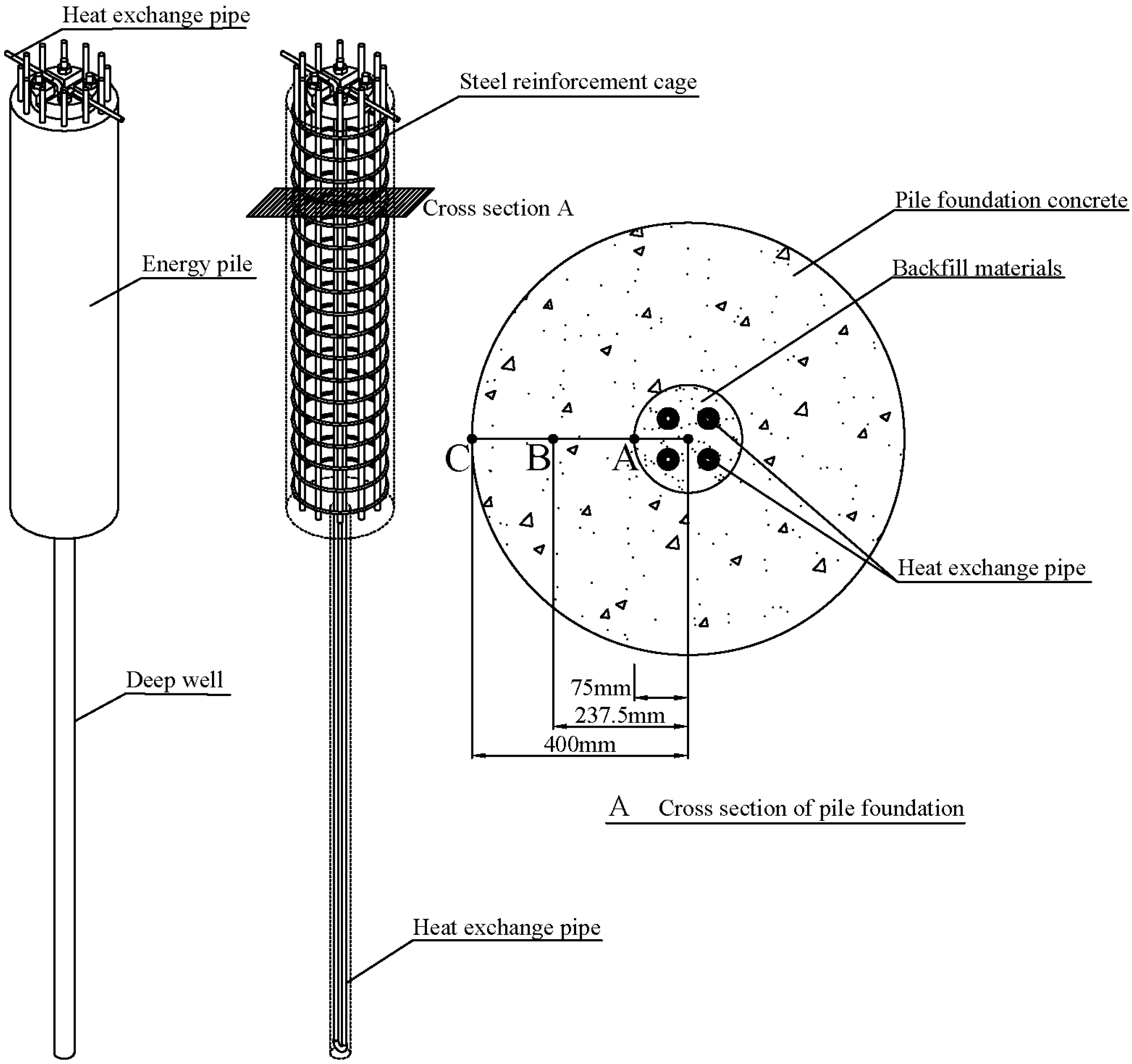
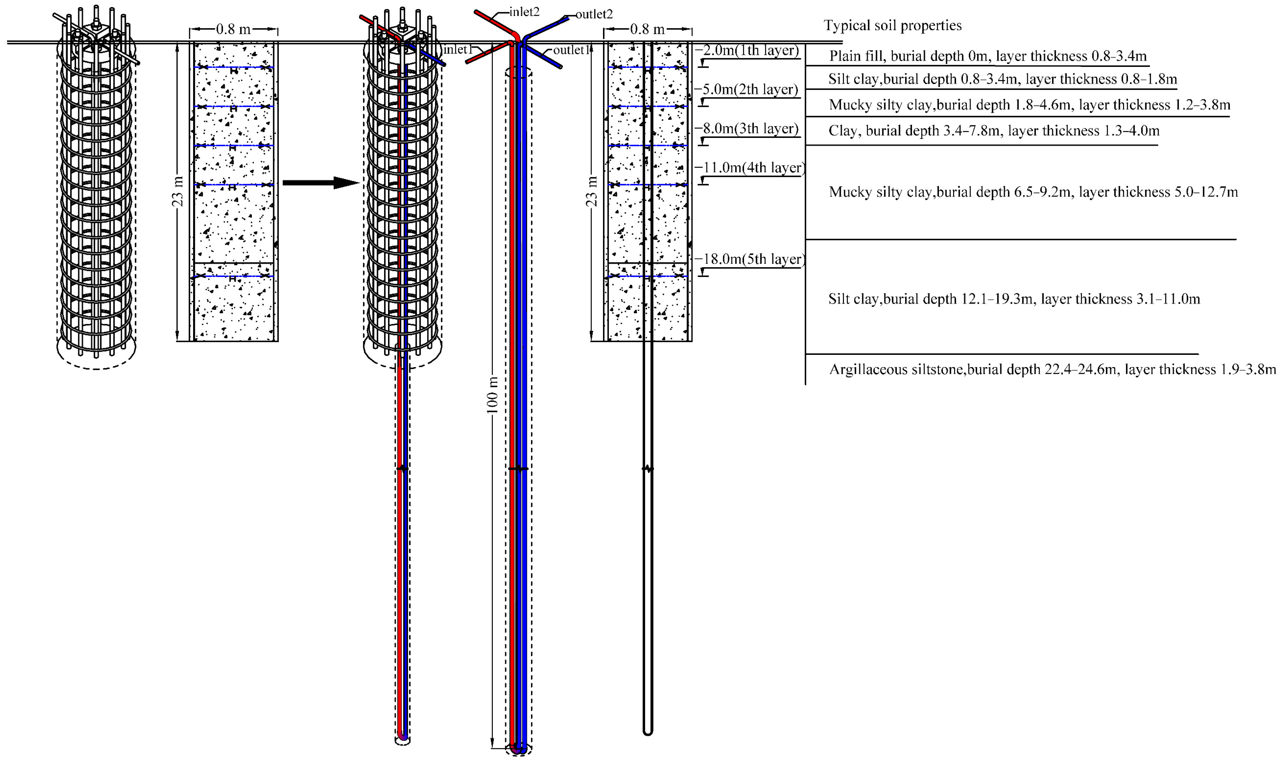
2.1. DBP-EP Structure

DBP-EP has a compound structure, which integrates GSHP and an embedded pipe energy pile. The heat-exchange pipe passes through the pile end and enters the deep well at the bottom of the pile to reach the optimal operating efficiency depth within the range of 100~300 m on the surface [5]. The thermal and mechanical properties of the DBP-EP will change due to variations within the structure, which will lead to prominent changes in the temperature field and stress field at the pile end. Therefore, it is necessary to further study the mechanical properties of DBP-EP. The schematic diagram of the overall structure of DBP-EP is shown in Figure 1.

2.2. Calculation of Thermomechanical Response of DBP-EP

Buried pipes in DBP-EP are arranged in a symmetrical double-U shape. Mainly due to the heat exchange between the pipe wall and the backfill material, the concrete of the pile body, the rock and soil around the pile and the temperature field are evenly distributed along the cross section of the pile [31]. In this paper, it is assumed that the strain distribution is uniform along the cross section of pile, with the same depth under the action of temperature load.
The pile without load expands when it is heated and shrinks when it is cooled. When it is regarded as a freely erected member, its deformation characteristics under thermal conditions satisfy the following equation:
ε T - Free = α c Δ T
where ε T - Free is the axial temperature strain of pile without constraint;
  • α c is the free expansion/contraction coefficient of concrete;
  • Δ T is the temperature change.
Under the action of temperature load, the measured axial average strain of the pile caused by temperature change should be less than the free strain calculated by Formula (1), namely:
ε ¯ T - Obs ε T - Free
where ε ¯ T - Obs is the measured axial average strain under temperature load (that is, the axial strain at point B in Figure 1).
Thus, the additional axial average strain under temperature load can be calculated as follows:
ε ¯ T - Rstr = ε T - Free ε ¯ T - Obs
where ε ¯ T - Rstr is the additional axial average strain of the pile under temperature load.
Therefore, the additional axial mean stress under temperature load can be calculated according to the following formula:
σ ¯ T - Rstr = E ε ¯ T - Rstr
where σ ¯ T - Rstr is the additional axial average stress of the pile under temperature load; E is the elastic modulus of concrete.
Thus, the additional axial average load can be calculated by the following formula:
P ¯ T = EA ε ¯ T - Rstr = EA ( α c Δ T ε ¯ T - Obs )
where A is the cross-sectional area of the pile body excluding the backfill material ( A = π ( R 2 r 2 ) );
P ¯ T is the additional axial average load of temperature.

3. Test Overview and Simulation Model

3.1. Project Overview
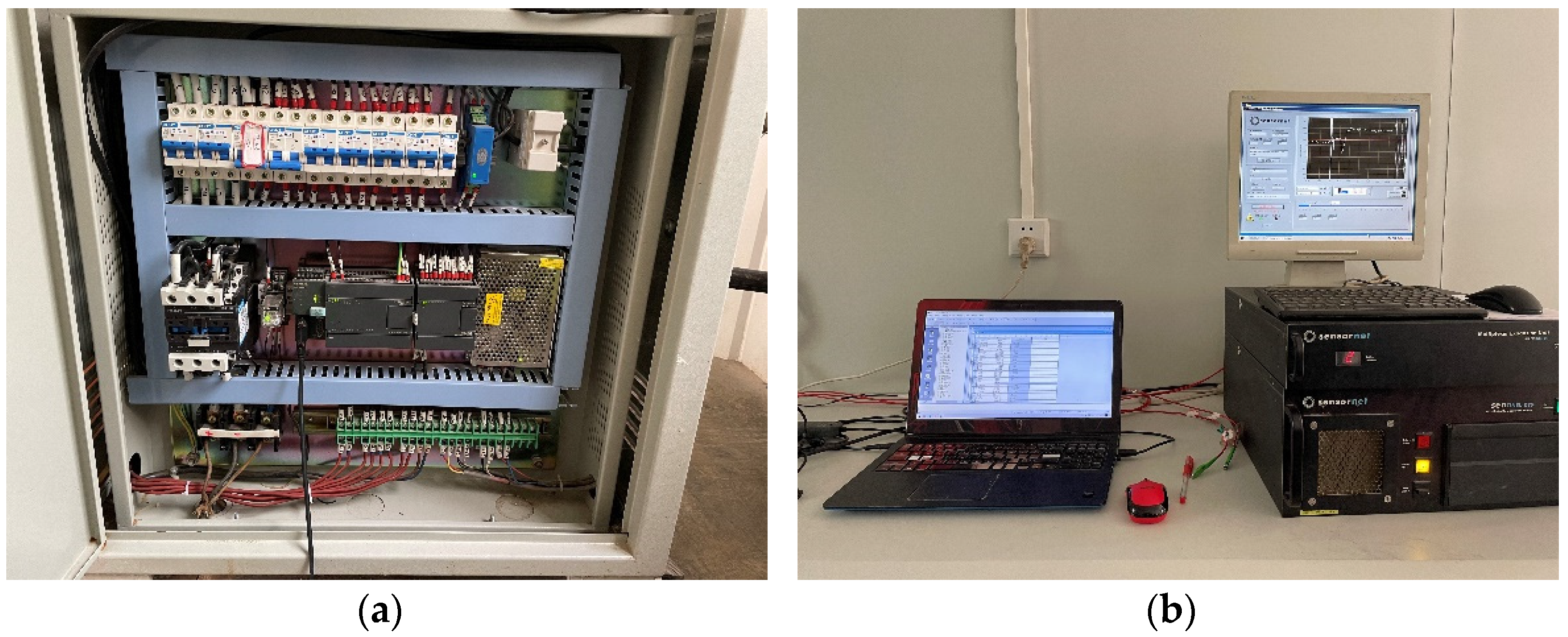
The test site is located in Hubei University of Technology, Wuhan. The DBP-EP is a bored pile with a diameter of 800 mm, a length of 23 m and a concrete strength of C30. After piling, the center of the pile is drilled; the aperture is 150 mm, the depth of drilling is 100 m and the diameter of the heat-exchange pipe is 25 mm. The symmetrical double-U parallel arrangement is adopted, and the distributed temperature measurement fiber is bound on the pipe wall. After completion, the U-type heat-exchange pipe is placed in the hole and backfilled with fine sand. Finally, the heat-exchange pipe is connected to the water collector, and the test is carried out by connecting the water collector to the test instrument.
The stratum distribution of the test site from top to bottom is clay, silty clay and highly-weathered argillaceous siltstone. The length of the test DBP-EP is 23 m, the pile tip is close to the rock layer and the deep underground well is 77 m. Jy-4058-type vibrating string strain gauges are arranged in five positions inside the pile body (2 m, 5 m, 8 m, 11 m and 18 m away from the pile top). Each layer sensor is composed of two axial strain gauges on the left and right. Due to the space limitations of pile concrete pouring, strain gauges can only be arranged on the reinforcement cage. The distribution of the soil layer, the size of the test pile and the embedded sensor are shown in Figure 2.

3.2. Test Scheme

The field test adopts the Thermal Response Test (TRT) and uses an electric heater (or refrigerator) to provide stable heat (or cooling) to heat (or cool) the circulating medium in the DBP-EP. We recorded the temperature response of the DBP-EP. The experiment was carried out at Hubei University of Technology in Wuhan from 22 to 28 September 2020, with an average temperature of 28 °C. Before the test, the DTS temperature-measurement system was used to record that the initial temperature of the stratum was stable at 18.5 °C, and the initial temperature of the formation remained basically unchanged along the depth direction. Since no load was applied on the pile top, the boundary conditions of the test pile were not constrained at the pile top, and there were constraints at the bottom and side of the pile. A HGNY-03 rock and soil thermal response instrument was used to heat the circulating liquid in the pile, and the inlet and outlet water temperature, heating power and flow rate of the DBP-EP system were monitored in real time. A distributed optical fiber temperature-measurement system (DTS) was used to collect the temperature data of the heat-exchange pipe wall during heating of the circulating medium, which is shown in Figure 3.
The heater continuously heated the DBP-EP at a power of 5.5 kW and a flow rate of 1.0 m3/h for 168 h; the inlet water temperature was finally heated to 30.5 °C and then the heater was turned off. During the heating process, the water temperature, heating power and flow rate of the inlet and outlet of the heat-exchange pipe are automatically collected and recorded every 1 min. The temperature of the wall of the heat-exchange pipe was collected throughout the process by DTS with a data interval of 1 m. At the same time, sensor (strain) data were manually recorded at certain intervals.

3.3. Finite Element Numerical Simulation

3.3.1. Basic Assumptions

We used the finite element analysis method to explore the thermodynamic structure response characteristics of DBP-EP under temperature loads. In practical engineering applications, considering the complexity of DBP-EP structures and the instability of soil temperature, the overall structural model needs to be simplified during numerical simulation, and the following assumptions were made:
(1)
The thermal physical properties of the soil around the pile, rock, and soil under the pile are uniform;
(2)
Groundwater seepage is not considered;
(3)
The thermal property of the reinforcement in the pile foundation is the same as that of concrete;
(4)
Rock and soil temperature around the pile foundation are uniform;
(5)
The effects of the pipe wall on heat transfer are ignored;
(6)
The pile–soil contact surface is regarded as rigid unit contact;
(7)
It is assumed that soil is an ideal elastoplastic model.

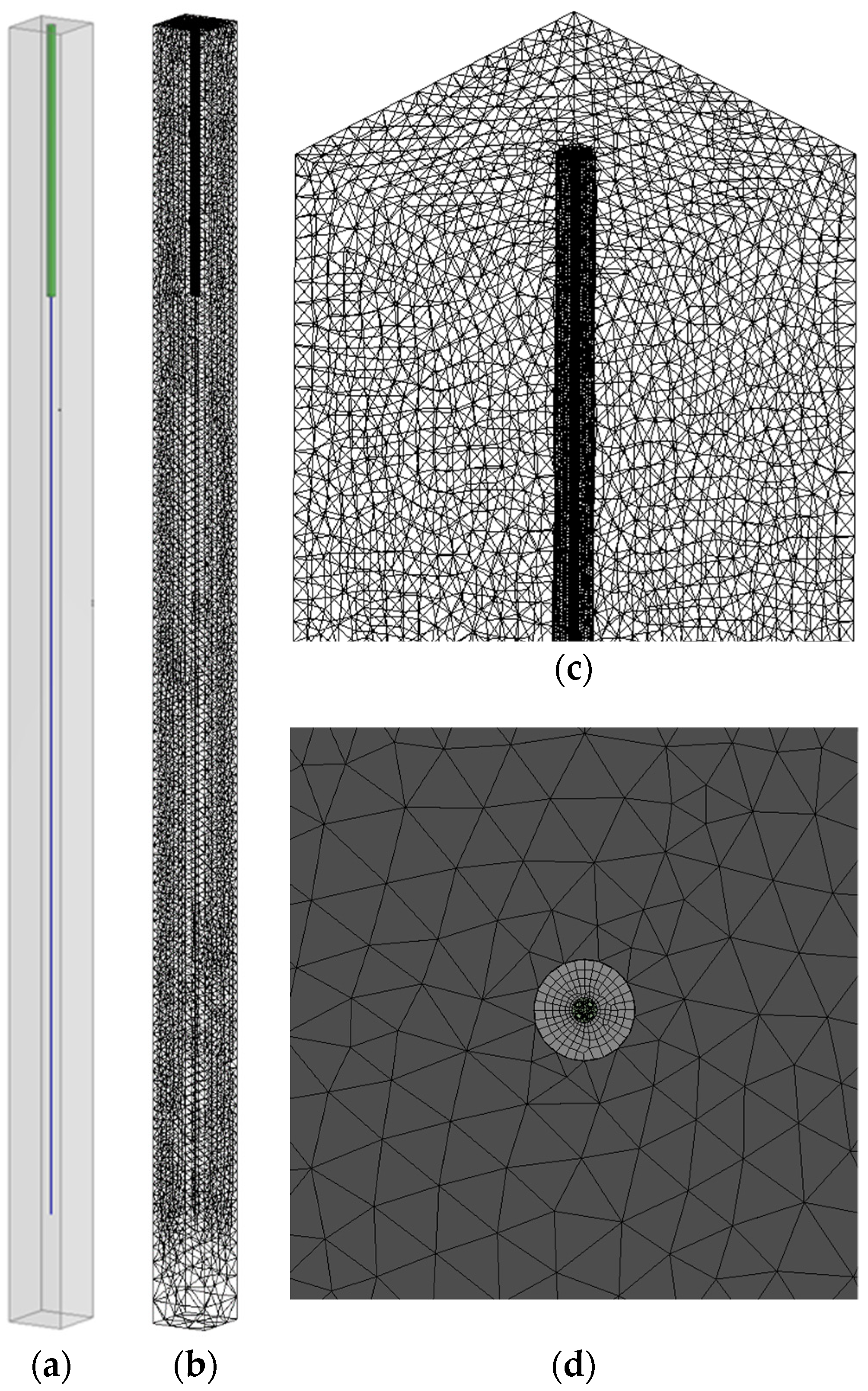
3.3.2. Model Building and Meshing

According to the actual size of the test pile, the model size is shown in Table 1. Tetrahedral and hexahedron mesh were used to mesh the model [34]. The overall model and mesh division are shown in Figure 4. The number of soil/rock mass backfill nodes and tetrahedral elements for the model are 631,109 and 410,424, respectively. The number of pile nodes and hexahedron elements for the model are 235,869 and 51,984, respectively. The simulation process used the Workbench platform to carry out the thermal fluid structure coupling under the heating and cooling conditions of the energy pile. The Fluent module was used to calculate the temperature field of the energy pile model, and then the temperature field of the pile and its periphery were imported into the statics module in the form of temperature load for calculation.

3.3.3. Physical Parameters and Research Conditions

In the field test, the temperature of each soil layer has a small variation along the depth direction and is basically stable. In order to simplify the calculation, the soil temperature in the numerical model used in this paper is uniformly set to 18.5 °C. The pile body adopts a linear elastic constitutive model. The thermophysical property parameters and physical and mechanical parameters of the soil, pile, heat-exchange fluid and heat-exchange pipe materials involved in the numerical simulation are obtained according to the on-site thermophysical property test [35], as shown in Table 2 and Table 3 below. The backfill material in the table is fine sand. Because the thermal conductivity of clay and silt clay are similar, this paper collectively refers to them as soil. In the numerical simulation, the model of DBP-EP was calculated after the inlet water temperatures were 30.5 °C (heating condition) and 6.5 °C (cooling condition) for 168 h. The test conditions are shown in Table 4 below.

4. Result Analysis and Discussion

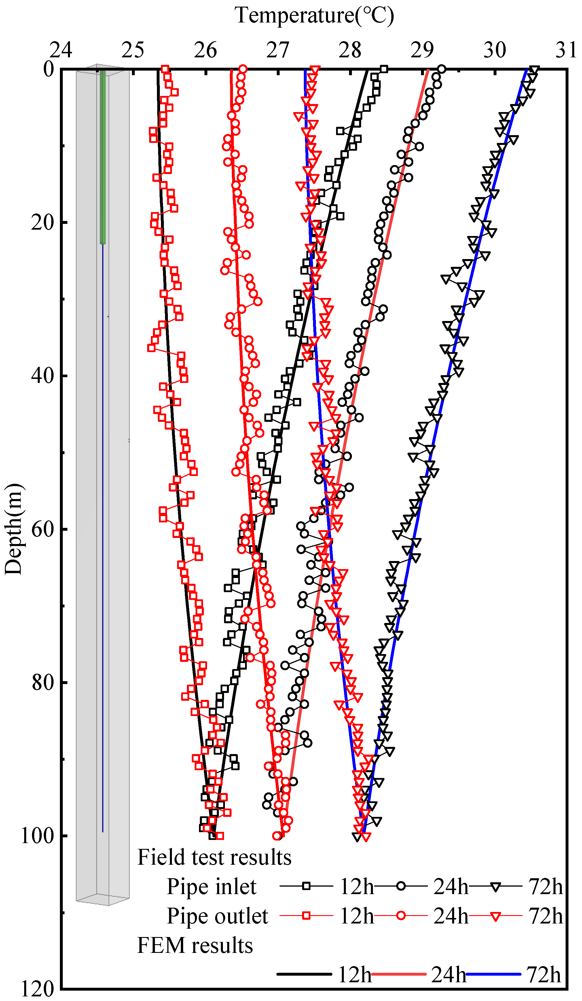
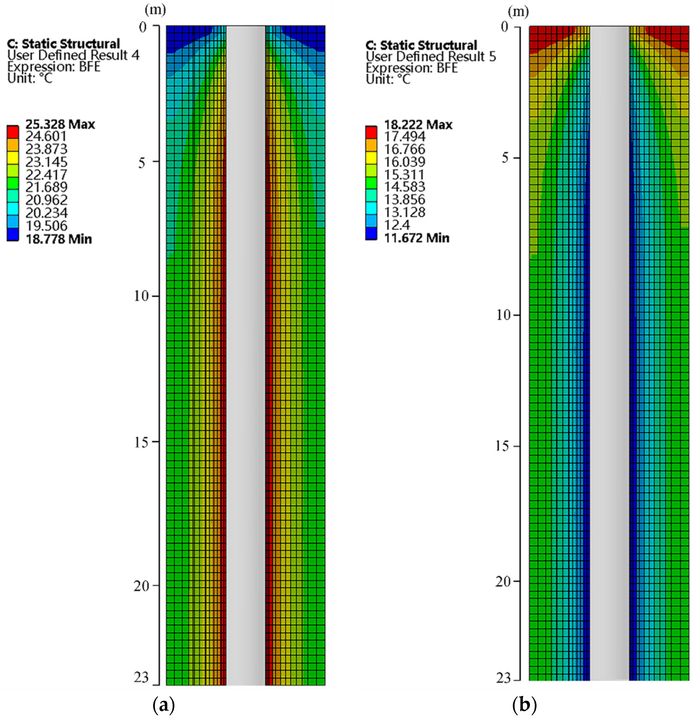
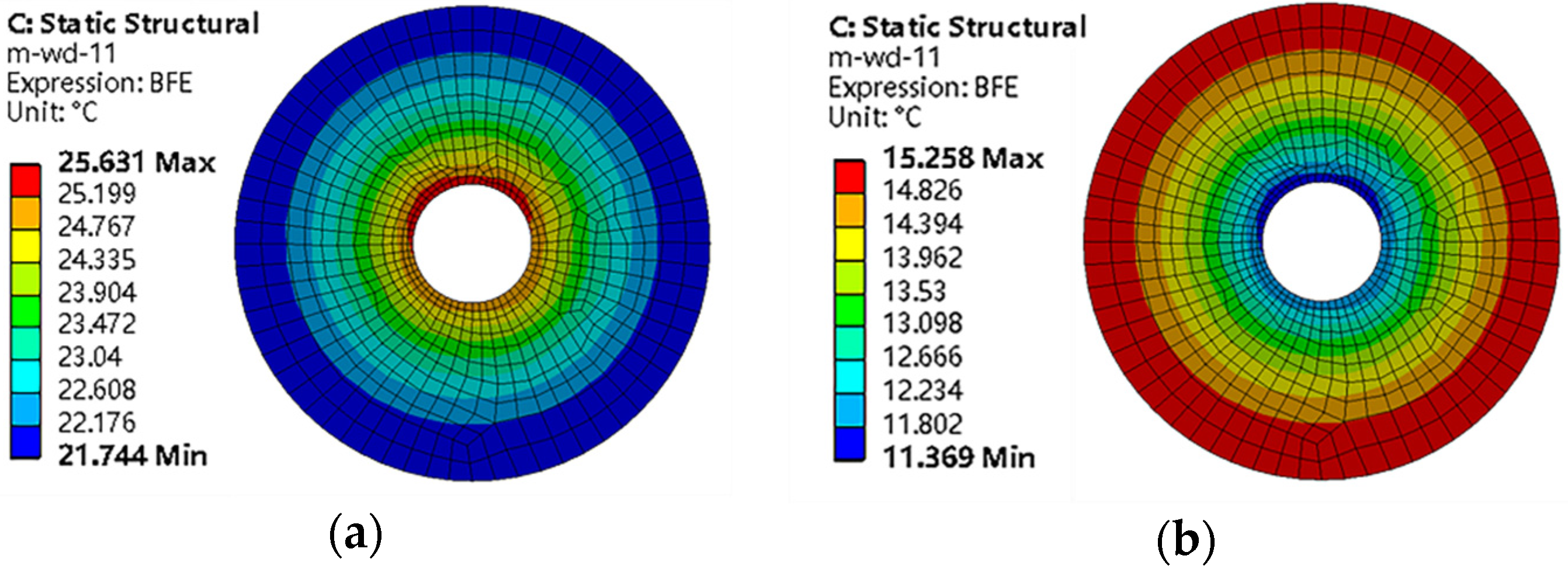
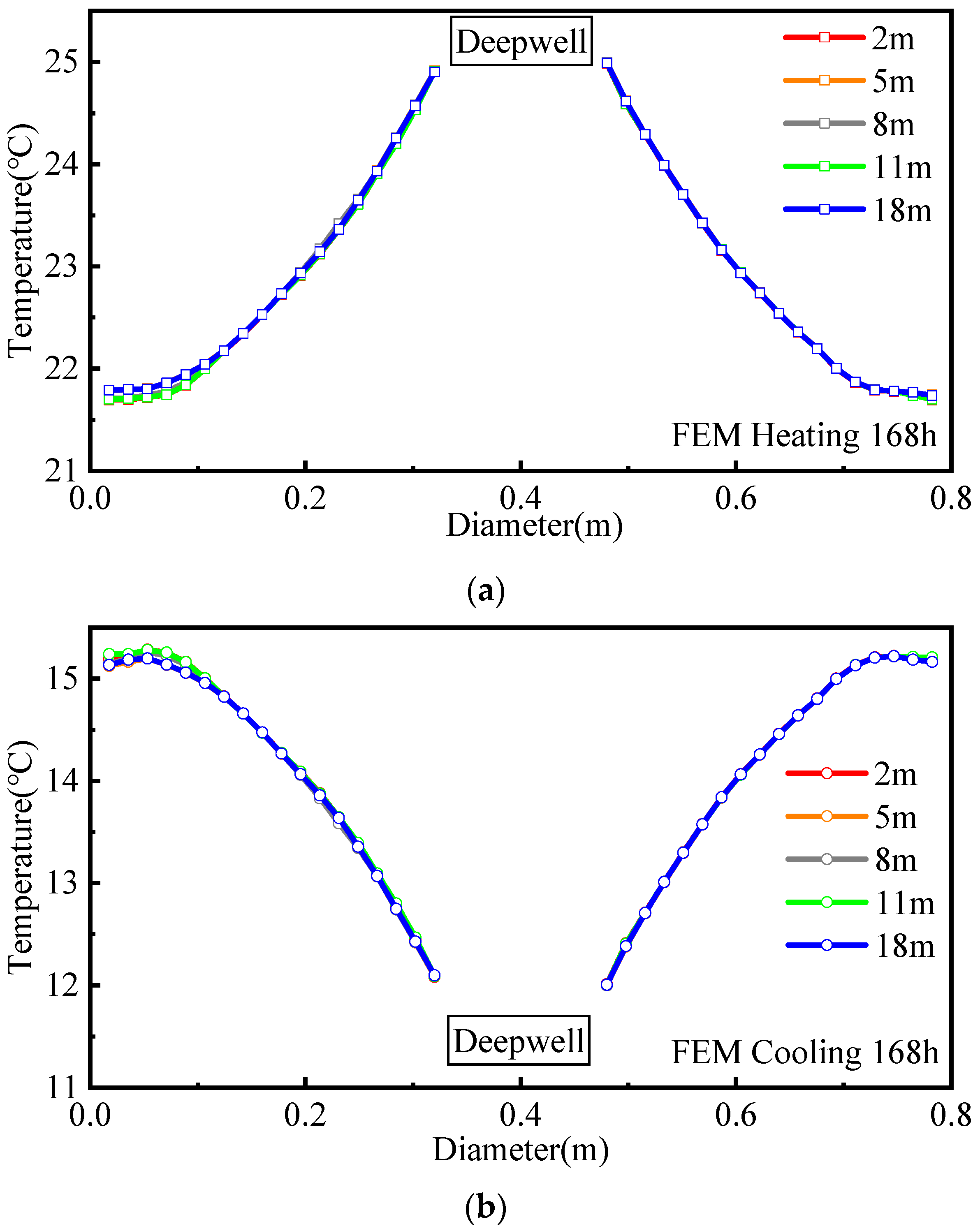
4.1. The Temperature Field Distribution Law

After the heat exchange is completed, the test results are compared with the numerical simulation; the temperature distribution law of the heat-exchange pipe along the depth direction is shown in Figure 5. When the test pile is running under heating conditions, the temperature of the inlet pipe of the heat-exchange pipe gradually decreases along the depth direction, the overall temperature change is relatively uniform and the temperature change conforms to the double-U symmetrical distribution. The field test uses 5.5 kW heating power to heat the test pile for 168 h. After heating for 72 h, the temperature at the inlet and outlet of the heat-exchange pipe reaches a stable state. In order to clearly understand the whole process of the temperature change of the DBP-EP with time, this paper selects 12 h, 24 h and 72 h to analyze the temperature field change of the pile body during the heating process. The results show that the temperature decrease rate of the inlet pipe of the heat-exchange pipe is significantly faster than that of the outlet pipe and the temperature difference of the inlet pipe is larger than that of the outlet pipe. The reason is that the heat-exchange pipe of the test pile is deeply buried, and the circulating water in the pipe exchanges heat sufficiently, but the water temperature in the inlet pipe is higher than that of the outlet pipe. This means that the temperature difference between it and the surrounding rock and soil is higher than that of the outlet pipe. On the other hand, the spacing between the inlet and outlet pipes of the heat-exchange pipe is small and the thermal interference phenomenon reduces heat transfer.
To estimate the deviations between the field experiment and the results of the numerical simulation, Python software was used to calculate the value of RMSE (named root-mean-squared error). This indicated that the value of RMSE is 0.144 after 12 h of the heating exchange operation. After 24 and 72 h of the heating exchange operation, the values of RMSE are 0.138 and 0.112, respectively. This shows that the result of the numerical simulation is consistent with the field measured data, and all values of the RMSE are much lower than 0.3. Therefore, the heat exchange transfer model is reliable in this study. Compared with the field test, the temperatures of the inlet and outlet pipes of the heat-exchange pipe at the upper part of the pile body are significantly lower than that of the field test. Because the upper part of the pile is in shallow soil, the temperature is greatly affected by the external environment (the average temperature of the external environment during the test is 28 °C), which will result in the simulated temperature of the water inlet and outlet pipes at 0 to 5 m in the upper part of the pile being lower than the field test temperature.
The temperature distribution of the longitudinal section of the test pile under heating and cooling conditions is shown in Figure 6. When the heat exchange is stable, the temperature of the pile varies more evenly along the depth. Because the heat-exchange pipe in the test pile passes through the bottom of the pile, there is no obvious change in the temperature field at the bottom of the pile, which is different from the temperature field distribution at the bottom of the IBP-EP in the pile [36]. We selected a pile depth of 11 m to analyze its cross-sectional temperature cloud picture, as shown in Figure 7. The temperature variation in the test piles displays a circular and dense distribution along the diameter of the pile; under heating conditions, the temperature distribution trend in the radial direction of the pile gradually decreases from the inside to the outside; under cooling conditions, the temperature distribution trend in the radial direction of the pile gradually increases from the inside to the outside.
We extracted the temperature distribution data in the radial direction at each depth of the pile under heating and cooling conditions in the simulation, as shown in Figure 8. The temperature variations in the energy piles along the depth direction are relatively similar; the temperature changes along the radial direction at the same depth are different, but the temperature changes are more uniform. Among them, under the heating condition of the energy pile (Figure 8a), the temperature distribution in the radial direction at each depth gradually decreases from the inside to outside; the overall average temperature of the pile body increases to 22.8 °C compared with the initial temperature of 18.5 °C; thus, it increased by 4.3 °C. The maximum temperature in the radial direction of the pile at each depth is up to 25.0 °C, the minimum temperature is 21.7 °C and the maximum temperature difference in the radial direction of each section reaches 3.3 °C. Under cooling conditions (Figure 8b), the radial temperature distribution at each depth gradually increases from the inside to the outside; the overall average temperature of the pile decreases to 14.3 °C, which is 4.2 °C lower than the initial temperature of 18.5 °C. The lowest temperature in the radial direction of the pile at depth is as low as 12 °C, the highest temperature is 15.3 °C and the maximum temperature difference in the radial direction of each section reaches 3.3 °C. When heating and cooling the pile, a temperature difference in the depth direction and radial direction of the pile appears, which is different from the temperature field distribution of the IBP-EP in the pile [7,8]. It is necessary to study the structural response of the pile under the action of temperature in detail.

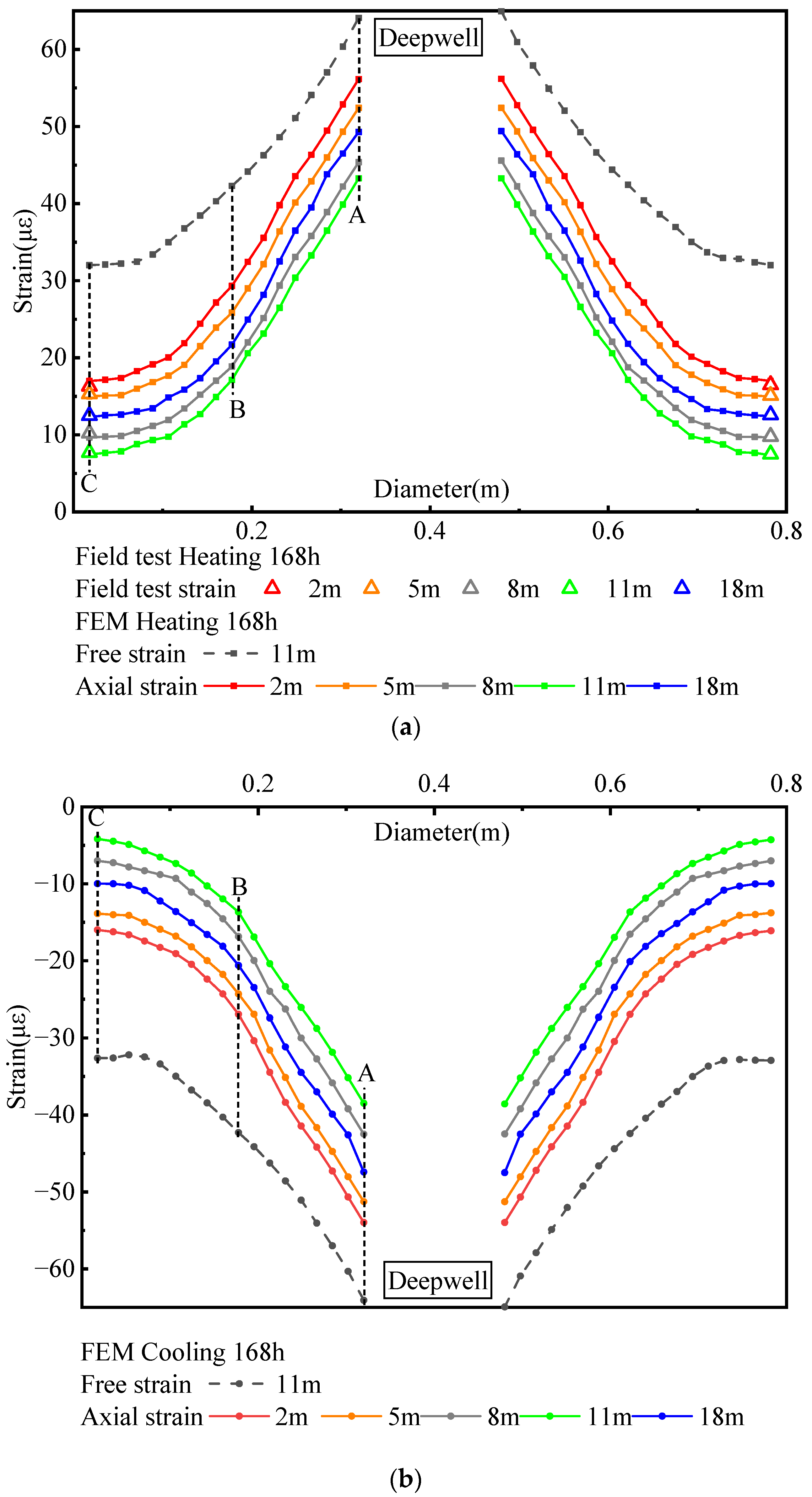
4.2. Axial Strain Distribution of Pile

Figure 9 shows the distribution of axial strain in the radial direction at each depth of the pile under heating and cooling conditions. According to Formula (1), the free strain in the radial direction at each depth is basically the same and the free strain distribution in the middle of the pile (at a depth of 11 m) is selected as the free strain distribution at each depth, as shown by the dotted line in Figure 9. The strain gauges used in the field test are embedded in the steel cage (at point C of the simulation data in the figure), and the axial strain values at the left and right are similar to the simulation results. Under heating and cooling conditions of the pile, the axial strain of the pile at the same depth gradually decreases from the inside to outside and the change is relatively uniform; the axial strain distribution in the radial direction at different depths is similar. In the radial direction at each depth, the axial strain of the A–B section is closer to the free strain than that of the B–C section. The reason is that the backfill material in contact with A has less restraint on A. Therefore, the strain in this position is closer to the free strain. Under the action of temperature load, due to the influence of the side friction of the soil around the pile and the restraint of the pile end, the axial strain generated in the middle of the pile body (at a depth of 11 m) is significantly smaller than the two ends of the pile body, and at each depth of the pile body, the maximum axial strain value generated along the radial direction is less than the free strain value.
Under heating conditions (Figure 9a), the pile body undergoes thermal expansion, meaning that the axial strain along the radial direction at each depth of the pile body is positive. The pile has the largest axial tensile strain at a depth of 2 m and its average axial strain value ( ε ¯ T - Obs ( 2 m ) ) reaches 29.4 με; the axial tensile strain is the smallest at a depth of 11 m and its average axial strain value ( ε ¯ T - Obs ( 11 m ) ) is 17.1 με. Under cooling conditions (Figure 9b), the pile body undergoes cold shrinkage and will tend to compress toward the middle, making the axial strain in the radial direction at each depth of the pile body appear to be negative. The pile has the largest axial compressive strain at a depth of 2 m and its average axial strain value ( ε ¯ T - Obs ( 2 m ) ) reaches −27.0 με; the axial compressive strain produced at a depth of 11 m is the smallest, with an average axial strain value ( ε ¯ T - Obs ( 11 m ) ) of −13.7 με. According to Formulas (3) and (4), since the minimum axial average strain of the cooling condition is significantly smaller than that of the heating condition, the additional axial average strain under the action of the temperature load is significantly greater than the heating condition, resulting in greater additional axial stress when the pile is cooled. Therefore, in the later operation of the DBP-EP, the structural response of the energy pile under cooling conditions should be considered.

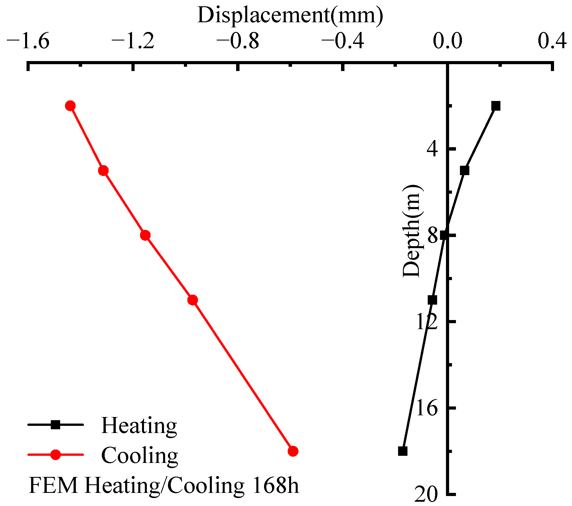
4.3. Pile Displacement Distribution

Figure 10 shows the variation in pile displacement with depth under heating and cooling conditions. Under heating conditions, the pile body expands and deforms towards both ends, and an upward bulge is generated in the upper part of the pile body. The displacement of the upward bulge at a position of 2 m reaches 0.19 mm. A downward settlement occurs at the middle and lower part of the pile body, and the displacement at 18 m reaches −0.17 mm. The zero displacement point of the pile body should be located in the middle of the pile when it is heated freely, and the zero displacement point of the pile body in this test is about 7 m in the middle and upper part of the pile body, which has a tendency to shift upwards compared to the free heating of the pile body.
Under cooling conditions, the pile body shrinks, while the upper part will have a downward displacement trend and the lower part, an upward one. Since the bottom of the pile is in contact with the rock and soil layer, the deformation is restrained to a certain extent, so the pile body is displaced downward as a whole. The maximum downward displacement of the pile at a depth of 2 m is −1.44 mm and the minimum displacement at a depth of 18 m is −0.59 mm. This is similar to the settlement of IBP-EP due to temperature changes [21,24]. Generally, the displacement of the pile is significantly smaller under heating conditions than under cooling. The settlement of the pile top under cooling conditions is larger and the connection between the reinforced pile and the foundation needs to be considered in the design.

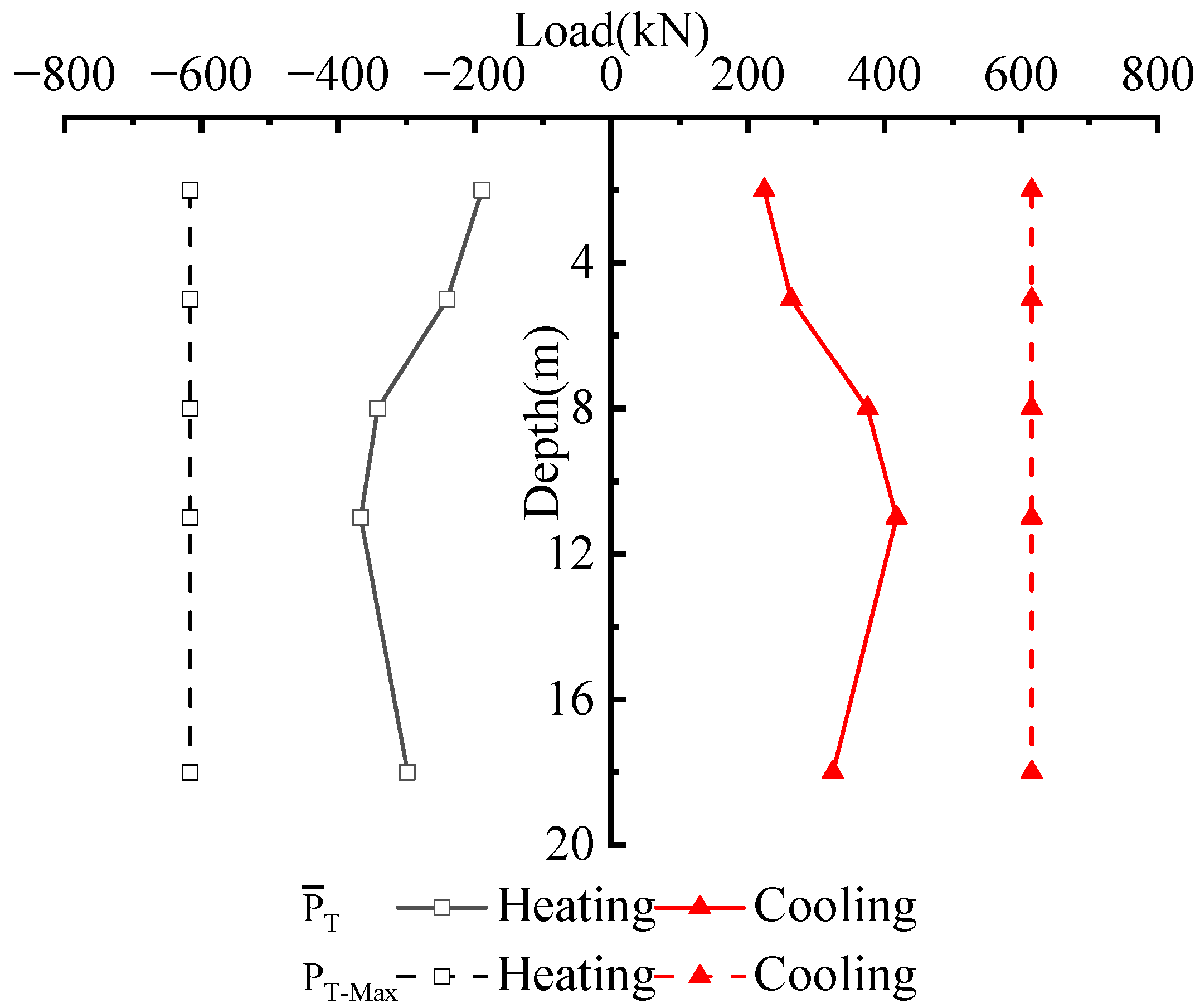
4.4. Additional Axial Average Load for Pile Body Temperature

Due to the restraint of the soil around the pile and the pile tip, the temperature change will generate additional axial load in the pile. According to Formula (5), we calculate the temperature-additional axial average load ( P ¯ T ) at different depths of the pile. Figure 11 shows the distribution of temperature-additional load with depth under heating and cooling conditions. The dotted line in the figure represents the additional temperature load when the pile is completely constrained under temperature load (PT-Max). It can be seen from the figure that the maximum ( P ¯ T ) of the pile body of the two working conditions appears in the middle section; the distribution law of the two ends is small and the middle is large along the pile depth, which is opposite to the distribution law of axial strain. Under heating conditions, the thermal expansion of the pile will generate additional axial pressure. The maximum ( P ¯ T ) appears at the position of 11 m and reaches −366.7 kN ( P ¯ T ( 11 m ) ), which corresponds to the average temperature rise of 4.3 °C. Under cooling conditions, the pile body undergoes cold contraction and will produce additional axial tension; its maximum ( P ¯ T ) also appears at the position of 11 m, reaching 417.6 kN ( P ¯ T ( 11 m ) ). The corresponding average temperature drop is 4.2 °C. In this test pile, under only the temperature load, the maximum axial average pressure increase during heating is −85.3 kN/°C and the maximum axial average tensile increase during cooling is 99.4 kN/°C, which shows that the temperature drop in the maximum ( P ¯ T ) of the pile changes more significantly.
According to the practical engineering application of DBP-EP, the temperature change in the pile body caused by heating or cooling conditions usually does not exceed 10 °C, which can be obtained by conversion with reference to the maximum additional axial average load change of the pile body under heating and cooling conditions. The maximum additional axial average tensile force can reach 994 kN and the maximum additional axial average pressure in the pile body can reach 853 kN when heated. The additional axial average load generated by the temperature change of the DBP-EP is slightly larger than that of the IBP-EP, which should be caused by the reduction of the cross-sectional area after the middle of the pile is replaced by the deep well [23]. Therefore, DBP-EP will produce non-negligible additional loads under the action of temperature loads. In the design stage of the DBP-EP structure, it is necessary to fully consider the impact of temperature changes on the bearing capacity of the pile during operation to ensure the structural safety of the building.

5. Conclusions

In this paper, a thermomechanical response test and numerical simulation of DBP-EP under temperature loading were carried out. The distribution of temperature field, axial strain, pile displacement and temperature-additional load of an energy pile under heating and cooling conditions were analyzed. The following conclusions were drawn:
(1)
Under heating and cooling conditions, the temperature field of the DBP-EP gradually changes from inside to outside at the same depth. The temperature inside the pile changes greatly, while the temperature field within the deep part of the well not surrounded by the pile does not change significantly, which is different from the temperature distribution inside the pile of IBP-EP;
(2)
The minimum axial average strain under cooling conditions is significantly smaller than that under heating conditions, and the additional axial average strain under temperature load is significantly larger than that under heating conditions, which leads to greater additional axial stress generated when the pile is cooled. The DBP-EP has a large settlement at the top of the pile under cooling conditions and the connection between the pile and the foundation should be considered in the design;
(3)
Under the action of temperature load only, the maximum axial average pressure increment during heating is −85.3 kN/°C and the maximum axial average tension increment during cooling is 99.4 kN/°C, all of which generate additional load that cannot be ignored. In the design stage of the DBP-EP structure, the influence of temperature change on pile bearing capacity should be fully considered to ensure the structural safety of buildings.

Author Contributions

Methodology, Z.C. and J.W.; software, J.W., B.W., D.H. and J.T.; validation, Z.C., J.W. and B.W.; formal analysis, J.W.; investigation, J.W. and J.T.; resources, Z.C. and H.X.; data curation, Z.C.; writing—original draft preparation, J.W.; writing—review and editing, Z.C. and C.C.; visualization, Z.C. and J.W.; supervision, Z.C. and C.C.; project administration, Z.C., C.C. and H.X.; funding acquisition, Z.C. and H.X. All authors have read and agreed to the published version of the manuscript.

Funding

The work presented in this paper was supported by the National Natural Science Foundation of China (No. 51808203, No. 52078194).

Conflicts of Interest

The authors declare no conflict of interest.

References

  1. Ma, W.B.; Gong, Y.L.; Zhao, D.Q.; Xu, Q.H.; Qin, H.S.; Chen, Y. Present situation and development of geothermal energy exploitation and utilization in China. Bull. Chin. Acad. Sci. 2016, 31, 199–207. [Google Scholar]
  2. Mao, J.F.; Pan, D.; Geng, S.B.; Chen, S.Y. Application research and prospect of ground source heat pump in underground engineering. Chin. J. Undergr. Space Eng. 2015, 11, 252–256. [Google Scholar]
  3. Liu, Y.; Zhao, J.; Li, Y. Influence of drilling depth on performance of ground source heat pump system. Acta Energ. Sol. Sin. 2015, 36, 2584–2589. [Google Scholar]
  4. Chen, C.; Ren, Y.; Wang, Y.F. Simulative and Experimental Study on the Heat Transfer Performance of Vertical Ground Heat Exchangers. J. Hunan Univ. Nat. Sci. 2009, 36, 49–53. [Google Scholar]
  5. Xiao, H.L.; Chen, Z.; Xiao, Y.; Ma, Q.; Que, M.K. Back-Drilling Deeply Buried Pipe Type Pouring Type Energy Pile Heat Exchange System and Construction Method. China Patent CN108444121A, 24 August 2018. [Google Scholar]
  6. Chen, Z.; Wang, B.; Zheng, L.F.; Xiao, H.L.; Wang, J.Q. Research on heat exchange law and structural design optimization of deep buried pipe energy piles. Energies 2021, 14, 6449. [Google Scholar] [CrossRef]
  7. Gui, S.Q.; Cheng, X.H.; Zhang, Z.P. Comparison of heat transfer performance between ground source heat pump pile foundation and borehole heat exchanger. J. Chongqing Jianzhu Univ. 2013, 35, 151–156. [Google Scholar]
  8. You, S.; Cheng, X.H.; Guo, H.X.; Yao, Z.Q. In-situ experimental study of heat exchange capacity of CFG pile geothermal exchangers. Energy Build. 2014, 79, 23–31. [Google Scholar] [CrossRef]
  9. Li, X.Y.; Guo, H.X.; Cheng, X.H. Experimental and numerical study on temperature distribution in energy piles. China Civ. Eng. J. 2016, 49, 102–110. [Google Scholar]
  10. Zhao, H.F.; Tang, R.B.; Gui, S.Q.; Luo, J.; Jia, J. Experimental study on temperature field distribution characteristics of rock and soil around double U-pipe energy pile. J. Civ. Archit. Environ. Eng. 2016, 38, 157–163. [Google Scholar]
  11. Liu, H.L.; Wu, D.; Kong, G.Q.; Wang, C.L.; Wu, H.W. Thermal response of energy piles with embedded tube and tied tube. Rock Soil Mech. 2017, 38, 333–340. [Google Scholar]
  12. Gashti, E.H.N.; Malaska, M.; Kujala, K. Evaluation of thermo-mechanical behavior of composite energy piles during heating/cooling operations. Eng. Struct. 2014, 75, 363–373. [Google Scholar] [CrossRef]
  13. Knellwolf, C.; Peron, H.; Laloui, L. Geotechnical Analysis of Heat Exchanger Piles. J. Geotech. Geoenviron. Eng. 2011, 137, 890–902. [Google Scholar] [CrossRef]
  14. Olgun, C.G.; Ozudogru, T.Y.; Abdelaziz, S.L.; Senol, A. Long-term performance of heat exchanger piles. Acta Geotech. 2015, 10, 553–569. [Google Scholar] [CrossRef]
  15. Sutman, M.; Olgun, C.G.; Laloui, L. Cyclic Load–Transfer Approach for the Analysis of Energy Piles. J. Geotech. Geoenviron. Eng. 2019, 145, 04018101. [Google Scholar] [CrossRef]
  16. Huang, X.; Kong, G.Q.; Liu, H.L.; Peng, H.F.; Hao, Y.H. Negative skin friction behavior of PCC energy pile under heating cycle. J. Disaster Prev. Mitig. Eng. 2017, 37, 511–517. [Google Scholar]
  17. Ng, C.W.W.; Shi, C.; Gunawan, A.; Laloui, L.; Liu, H.L. Centrifuge modelling of heating effects on energy pile performance in saturated sand. Can. Geotech. J. 2014, 52, 1045–1057. [Google Scholar] [CrossRef]
  18. Salciarini, D.; Ronchi, F.; Cattoni, E.; Tamagnini, C. Thermomechanical Effects Induced by Energy Piles Operation in a Small Piled Raft. Int. J. Geomech. 2015, 15, 04014042. [Google Scholar] [CrossRef]
  19. Di, D.A.; Laloui, L. Numerical analysis of the geotechnical behavior of energy piles. Int. J. Numer. Anal. Methods Geomech. 2015, 39, 861–888. [Google Scholar] [CrossRef]
  20. Gawecka, K.A.; Taborda, D.M.G.; Potts, D.M.; Cui, W.; Zdravkovic, L.; Kasri, M.S.H. Numerical modelling of thermo-active piles in London Clay. Proc. Inst. Civ. Eng. 2017, 170, 201–219. [Google Scholar] [CrossRef] [Green Version]
  21. Kong, G.Q.; Wang, C.L.; Liu, H.L.; Wu, D.; Che, P. Analysis of pile head displacement of energy pile under repeated temperature cycling. Rock Soil Mech. 2017, 38, 958–964. [Google Scholar]
  22. Wang, C.L.; Liu, H.L.; Kong, G.Q.; Ng, C.W.W. Model tests of energy piles with and without a vertical load. Environ. Geotech. 2016, 3, 203–213. [Google Scholar] [CrossRef] [Green Version]
  23. Chen, Z.; Sun, Y.; Xiao, H.L.; Ma, Q.; Zhang, L.G. In-Situ Thermomechanical Response Test of an Energy Pile Under Temperature Loading. Arab. J. Sci. Eng. 2021, 46, 10355–10364. [Google Scholar] [CrossRef]
  24. Jiang, G.; Li, R.F.; Wang, H.; Chen, G.; Lu, H.W.; Shao, D. Numerical analysis of the bearing capacity of floating energy piles during the full process of thermal-mechanical coupling. Chin. J. Rock Mech. Eng. 2019, 38, 2525–2534. [Google Scholar]
  25. Huang, Y.P.; Jiang, G.; Lu, H.W.; Song, Z.; Xu, X.L.; Hong, X. Thermal-mechanical coupled load transfer method of energy pile based on exponential model. J. Nanjing Tech Univ. Nat. Sci. Ed. 2019, 41, 96–103. [Google Scholar]
  26. Lu, H.W.; Jiang, G.; Wang, H.; Hong, X.; Shi, C.L.; Gong, H.W.; Liu, W.Q. In-situ tests and thermo-mechanical bearing characteristics of friction geothermal energy piles. Chin. J. Geotech. Eng. 2017, 39, 334–342. [Google Scholar]
  27. Goode, J.C.; Mccartney, J.S. Centrifuge Modeling of End-Restraint Effects in Energy Foundations. J. Geotech. Geoenviron. Eng. 2015, 141, 04015034. [Google Scholar] [CrossRef] [Green Version]
  28. Kalantidou, A.; Tang, A.M.; Pereira, J.M. Preliminary study on the mechanical behaviour of heat exchanger pile in physical model. Géotechnique 2013, 62, 1047–1051. [Google Scholar] [CrossRef] [Green Version]
  29. Laloui, L.; Nuth, M.; Vulliet, L. Experimental and numerical investigations of the behavior of a heat exchanger pile. Int. J. Numer. Anal. Methods Geomech. 2006, 30, 763–781. [Google Scholar] [CrossRef]
  30. Bourne-webb, P.J.; Amatya, B.; Soga, K.; Amis, T.; Davidson, C.; Payne, P. Energy pile test at Lambeth College, London: Geotechnical and thermodynamic aspects of pile response to heat cycles. Géotechnique 2009, 59, 237–248. [Google Scholar] [CrossRef]
  31. Chen, Z.; Yao, J.W.; Pan, P.; Xiao, H.L.; Ma, Q. Research on the heat exchange characteristics of the deeply buried pipe type of energy pile. Case Stud. Therm. Eng. 2021, 27, 101272. [Google Scholar] [CrossRef]
  32. Lyu, W.D.; Pu, H.F.; Xiao, H.L.; Hu, D.W.; Ma, Q. Thermal performance of energy pile with deeply penetrating 1-U-shape heat exchanger. Geothermics 2021, 91, 102023. [Google Scholar] [CrossRef]
  33. Lyu, W.D.; Pu, H.F. Analysis on Factors Influencing Heat Transfer Performance of Energy Pile with Deeply Penetrating Heat Exchanger. Adv. New Renew. Energy 2021, 9, 1–10. [Google Scholar] [CrossRef]
  34. Coniglio, S.; Gogu, C.; Morlier, J. Weighted average continuity approach and moment correction: New strategies for non-consistent mesh projection in structural mechanics. Arch. Comput. Methods Eng. 2019, 26, 1414–1443. [Google Scholar] [CrossRef] [Green Version]
  35. Chen, Z.; Gao, H.Y.; Xiao, H.L.; Ma, Q.; Que, M.K. In-situ Thermo-mechanical Response Test of Perfusion Energy Pile under Temperature Loading. J. Disaster Prev. Mitig. Eng. 2019, 39, 592–598. [Google Scholar]
  36. Zhao, H.F.; Gui, S.Q.; Li, Q.; Jia, J. Temperature Field Distribution in Energy Pile with Buried Spiral Pipe: Characteristics and Influence Factors. J. Yangtze River Sci. Res. Inst. 2017, 34, 153–158. [Google Scholar]
Figure 1. Schematic diagram of overall structure of deep buried pipe energy pile (Point A is located on the inner wall of pile foundation, point C is located on the outer wall of pile foundation, and point B is located in the middle of AC).
Energies 15 03842 g001
Figure 2. Soil layer distribution, test pile size and sensor-burying diagram.
Energies 15 03842 g002
Figure 3. (a) Thermal responder; (b) DTS.
Energies 15 03842 g003
Figure 4. Schematic diagram of the whole model and grid division. (a) Overall model diagram; (b) overall grid diagram of the model; (c) upper grid diagram; (d) pile top grid diagram.
Energies 15 03842 g004
Figure 5. The temperature distribution law of the heat-exchange pipe along the depth direction.
Energies 15 03842 g005
Figure 6. The temperature distribution of the longitudinal section of the pile: (a) heating condition; (b) cooling condition.
Energies 15 03842 g006
Figure 7. Cross-sectional temperature cloud picture at a position of the pile at depth of 11 m: (a) heating condition; (b) cooling condition.
Energies 15 03842 g007
Figure 8. Temperature distribution in the radial direction at each depth of the pile: (a) heating condition; (b) cooling condition.
Energies 15 03842 g008
Figure 9. Axial strain distribution diagram in the radial direction at each depth of the pile: (a) heating condition; (b) cooling condition.
Energies 15 03842 g009
Figure 10. The variation curve of pile displacement with depth.
Energies 15 03842 g010
Figure 11. The distribution law of temperature-additional load along depth.
Energies 15 03842 g011
Table 1. Model size of deep buried pipe energy pile.
Soil Length (m)Soil Width (m)Soil Height (m)Pile Diameter (m)Pile Depth (m)Pipe Diameter (m)Pipe Thickness (m)Pipe Distance (m)Pipe Depth (m)
881020.8230.0250.0040.1100
Table 2. Thermal and physical properties of each entity unit.
MaterialThermal Conductivity (W/(m·K))Specific Heat Capacity (J/(kg∙K))Thermal Expansion Coefficient (m/°C)
Soil/rock mass1.9822405 × 10−6
Concrete2.29701 × 10−5
Backfill0.589665 × 10−6
Water0.64182-
Heat-exchange pipe0.452300-
Table 3. Physical and mechanical parameters of each entity unit.
MaterialDensity (kg/m3)Elastic Modulus (GPa)Poisson RatioCompressive Strength (MPa)Shear Modulus (GPa)Force of Cohesion (kPa)Angle of Internal Friction (°)
Soil19700.020.350.20.007911.6
Rock mass197019.50.2508.13911.6
Concrete2500300.183012--
Backfill2650300.3412--
Water998------
Heat-exchange pipe950------
Table 4. Numerical simulation test scheme of deep buried pipe energy pile.
NumberWorking ConditionInitial Temperature (°C)Inlet Water Temperature (°C)Flow Rate (m3/h)Assay Parameters
1Heating18.530.51.0Temperature field
Axial strain
Displacement
Temperature additional load
2Cooling18.56.51.0Temperature field
Axial strain
Displacement
Temperature additional load
Publisher’s Note: MDPI stays neutral with regard to jurisdictional claims in published maps and institutional affiliations.

