
High-Performance Fractional Order PIMR-Type Repetitive Control for a Grid-Tied Inverter

1
Zhongyuan-Petersburg Aviation College, Zhongyuan University of Technology, Zhengzhou 450007, China
2
School of Electronic and Information, Zhongyuan University of Technology, Zhengzhou 450007, China
3
Deparment of Electronic and Computer Engineering, Ritsumeikan University, Kusatsu 525-0058, Shiga, Japan
*
Authors to whom correspondence should be addressed.
†
These authors contributed equally to this work.
Energies 2022, 15(11), 3854; https://0-doi-org.brum.beds.ac.uk/10.3390/en15113854
Submission received: 8 April 2022
/
Revised: 16 May 2022
/
Accepted: 21 May 2022
/
Published: 24 May 2022
(This article belongs to the Topic Optimisation, Optimal Control and Nonlinear Dynamics in Electrical Power, Energy Storage and Renewable Energy Systems, 2nd Volume)
Abstract
:Low switching frequency is usually used in high-power wind grid-tied inverter systems to reduce power loss caused by on–off switching activity. Proportional integral multi-resonant type repetitive control (PIMR-type RC) can track reference grid current signals and suppress harmonic signals of grid-tied inverter system. A low switching frequency will result in a low sampling rate of control system. However, integer-order phase-lead compensation will lead to a poor compensation accuracy of PIMR-type RC with a low sampling rate, leading to poor tracking and suppressing performance of PIMR-type RC, and even result in system instability. To solve these problems, a high-performance fractional-order phase-lead compensation PIMR-type RC (FO-PIMR-RC) scheme is proposed in this paper. Fractional-order phase-lead compensation is adopted to compensate accurately the phase lag caused by controlled plant and PIMR-type RC and approximately realized by a finite impulse response (FIR) filter. Stability analysis and harmonic suppression performance are provided, and the parameter optimization design is implemented. Simulation and experimental results prove the desirable performance of the proposed control scheme.
1. Introduction
A pulse width modulated (PWM) grid-tied inverter has been diffusely utilized in power generation systems based on new energy [1,2,3]. Harmonic pollution caused by dead-time in PWM inverters or nonlinear loads may lead to device malfunction, power losses, and even induce system instability [4]. Therefore, a grid-tied inverter system with a high-quality output current is necessary. Low total harmonic distortion (THD) is an important target for output current.
The current harmonics at integer multiples of the fundamental frequency can be suppressed by certain excellent current control schemes, such as proportional resonant (PR) [5,6] proportional multi-resonant (PMR) [7], and repetitive control (RC) [8,9]. Proportional integral (PI) and PR controllers exhibit poor performance in coping with multiple current harmonics in single grid-tied inverters, whereas PMR controllers can solve the problem of multi-frequency current harmonics rejection [10,11,12,13]. Clearly, the implementation of many parallel resonant controllers might result in a significant increase in computational burden and control complexity.
Repetitive controllers can simultaneously track multiple periodic signals and bear much lower computational cost and lower tuning complexity due to recursive form compared to the PMR controller. In addition, they provide a simple but effective solution for eliminating low-frequency current harmonics [4,14]. However, repetitive controllers with limited control gain lead to poor dynamic performance [4,9]. In order to improve the dynamic-response speed of RC, some hybrid control schemes composed of RC and the existing high-dynamic controller (i.e., PI) are proposed, such as the cascade connection of RC and PI, or the parallel connection of RC and PI [15]. However, these hybrid control schemes are imperfect due to parameter coupling of the two controllers. Based on the relationship between RC and PMR, Zhao et al. [16] proposed a proportional inertial multi-resonant type RC (PIMR-type RC) scheme based on an improved RC and proportional gain. The proportional gain allows the PIMR-type RC to accommodate a larger control gain, thus leading to a faster error convergence rate and better low-frequency current harmonics suppressing performance.
In general, the RC system will exhibit optimal harmonic suppression performance if the controlled plant of the RC bears an amplitude-frequency characteristic of zero gain and a phase-frequency characteristic of zero phase. However, the inevitable phase lag of the inverter system will destroy the phase-frequency characteristic of zero phase; therefore, certain methods are employed to compensate the phase lag, which can also stabilize the inverter system with a larger gain and afaster convergence rate. Ye et al. [17] proposed a real-time noncausal phase-lead FIR filter to improve the performance of add-on repetitive controlled PWM DC–AC converters. A simple and efficient linear phase-lead compensation RC scheme is proposed in [18] to develop high-performance power converter systems. The linear phase-lead compensator, a noncausal operator and m being the phase lead step, aids in the harmonic suppression and faster convergence rate of a repetitive controller with a smaller steady-state error, and a wider stability region [19,20].
The linear phase-lead compensator can provide a phase lead at the angular frequency , where is the Nyquist frequency and is sampling frequency. With regard to RC, it is of interest to study the compensation at the fundamental frequency of the input reference signal and its harmonics, where is the reference signal frequency. Therefore, the phase-lead compensation resolution of linear-phase compensator is . Clearly, a high fundamental frequency , or low Nyquist frequency will lead to a lower phase-compensation resolution, such as AC ground power-supply unit [21], and low switching frequency wind-power system [22]. Inaccurate phase-lead compensation deteriorates RC control performance and even destabilizes the system [23].
Due to a pure delay line in the RC structure, the Conventional RC (CRC) requires a large memory space to store the error data of previous period(s), which will result in a notably increased hardware cost [24], especially, when the sampling frequency is high. In order to decrease the hardware cost, multirate RC [25] and low sampling frequency RC [26] are proposed, by means of reducing the sampling frequency of RC to relieve the memory cell consumption and decrease the computational burden. Furthermore, the low switching frequency scheme is often adopted in high-power applications to decrease switching power losses. Whereas the switching frequency is usually the same as or a half as high as the sampling frequency [27], and therefore the sampling frequency can also be reduced when a controller with low sampling frequency is used.
However, a low sampling frequency will decrease the phase-compensation resolution and result in the degradation of the control performance. Therefore, an improved RC with accurate phase-lead compensation is necessary.
In order to improve the accuracy of phase-lead compensation of RC with low phase resolution, some fractional phase-lead compensation schemes of RC are developed [23,24,26,28]. Ye et al. [24] proposed a cyclic repetitive control scheme for a PWM converter to achieve high-tracking accuracy and low THD with much lower memory space requirements. Ye et al. [28] developed an optimized switching law of RC via a switching integral phase-lead compensator to maximize the compensation performance. However, the design of the optimized switching RC scheme is performed offline, and any inaccuracies of the model will lead to a deterioration in compensation performance.
Another way to address the inaccuracy problem is to approximate the fractional part of , m being a fraction, using a Lagrange-interpolation-based finite impulse response (FIR) filter [23,26]. The FIR filter only requires a small number of multiplications and additions for coefficient updates, and is well-suited for fast online tuning of the fractional part [29].
A PIMR-type RC with a high sampling rate exhibits an excellent current harmonics suppressing performance and a fast dynamic response. However, the PIMR-type RC with low sampling frequency may result in a bad current harmonic suppression performance. To solve the problem, a fractional order phase lead compensation PIMR-type RC (FO-PIMR-RC) scheme based on an FIR filter is proposed for a grid-tied inverter. An FIR filter can approximate the fractional order phase-lead compensator, and enhance the phase-compensation accuracy of the PIMR-RC. The FO-PIMR-RC scheme simultaneously and accurately compensates phase lag under low sampling frequency, and addresses the issue of low-frequency current harmonics suppression.
2. Linear Phase Lead Compensation PIMR-Type RC
2.1. PIMR-Type RC
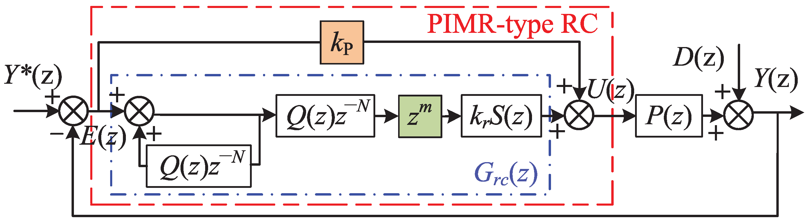
The PIMR-type RC controller consists of a proportional gain in parallel with an RC controller, as shown in Figure 1. is the tracking error between the reference input and the system output , is the disturbance, is the plant model, is a constant or a zero-phase low-pass filter used to improve system stability, is the period delay in which N is the ratio of the sampling frequency to the fundamental frequency , is a low-pass filter that is used to further attenuate high-frequency signals, is the RC gain and is the phase lead compensator that compensates the phase delay caused by and .
The tracking error between the reference input and disturbances , as shown in Figure 1, can be written as
where , and .
The stability conditions of the system are [16]: ➀ the roots of the polynomial are within the unit circle. ➁ . Further analysis shows that ➀ can be satisfied by selecting an appropriate , and ➁ can be written as
If the frequencies of the reference signal and the disturbance meet , with ( for even N and for odd N), then [18]. The stability condition ➁ can be satisfied if
Equality (3) implies that if the vector is within a unit circle with a radius, while increases from zero to the Nyquist frequency, then the PIMR-type RC system is stable. is defined as . increases the radius of the unit circle to improve the stability of the system. is an inverter output filter model, and maintaining a constant in the low-bandwidth is a desirable characteristic of RC. is usually chosen as a low-pass filter to further attenuate the high-frequency disturbance signals. It generally maintains 0dB in the bandwidth, so that remains a constant in the control bandwidth. This provides the possibility to design the RC gain to satisfy . Phase lead compensator is used to compensate , so that the phase of is between .
2.2. Analysis of Harmonic Suppression Performance of PIMR-Type RC
In Figure 1, the transfer function between and can be derived
where . If is defined as , then (4) can be expressed
where is harmonic attenuation and .
Equation (5) indicates that magnitude of represents harmonic rejection capability. It is clear that a smaller means a better attenuation performance of the disturbance signals.
When ,
and then,
Equation (7) means that for any periodic reference signal with a frequency lower than the Nyquist frequency, the steady-state tracking error is zero. However, is usually chosen as a constant less than 1 or a zero-phase low-pass filter to ensure system stability, therefore it will increase the steady-state error.
When ,
From Equation (8), when is small, a small tracking error can be guaranteed. In order to ensure the stability of the system, should have a phase shift as small as possible, which can be achieved by adjusting . Therefore, it is important to consider phase lead compensation.
Phase lead compensator provides a phase lead at the angular frequency , which compensates the phase lag of and , where is the Nyquist frequency and is the sample frequency. The low sampling frequency can release the heavy computational burden and memory space, but will result in low phase-compensation accuracy. When m is an integer, PIMR-type RC with phase lead compensation may easily lead to overcompensation or undercompensation, which deteriorates stability and tracking accuracy. Thus, it is desirable to adopt a high accuracy fractional-order phase-lead compensation.
3. Design of Fractional-Order Linear Phase Lead Compensation PIMR-Type RC
Integer-order phase-lead compensation PIMR-type RC has low accuracy at low sampling frequencies [30]. High-performance fractional-order linear phase with low THD, small steady-state error, and fast dynamic response will solve the problem of low accuracy.
3.1. Fractional-Order Linear Phase Lead Compensation (FOPL) and Implementation
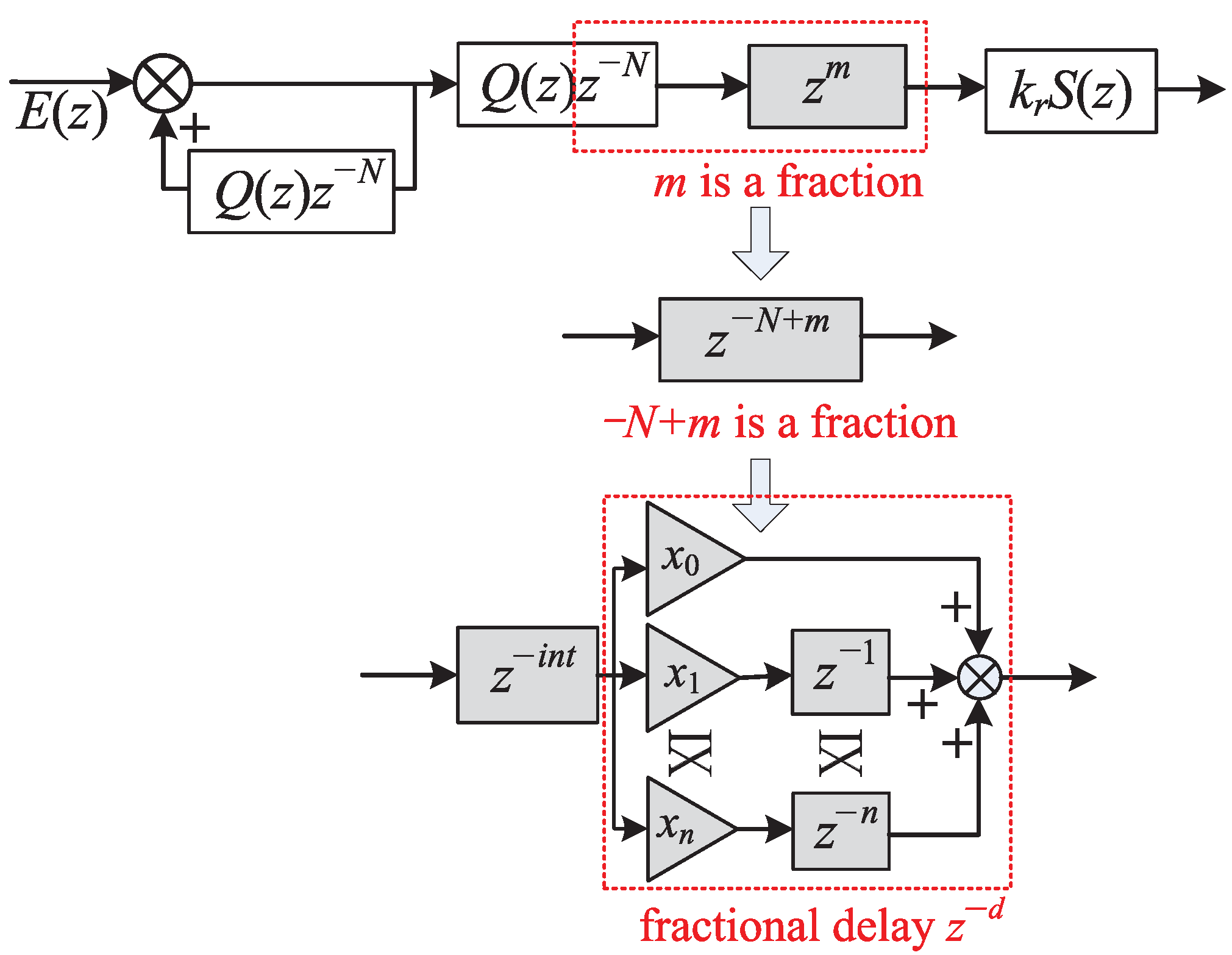
The FO-PIMR-RC scheme based on FIR filter is shown in Figure 2. The phase lead compensator is combined with the RC internal mode delay , which is . Since , is still a delay link that can be implemented in practice. When m is a fraction, can be separated into an integer part and a fraction part .
The fractional delay can be approximated by an M-order polynomial
where M is the order of filter, and is the polynomial coefficient, n = 0, 1, 2, 3,..., M. For the tradeoff of approximation accuracy and design complexity, a third-order FIR filter is selected in practical applications [23]. When , the interpolation effect is optimal [31].
3.2. Stability of PIMR-RC with FOPL
Based on the stability analysis in Section 2 and the implementation method of FIR filter [16], the stability condition of FO-PIMR-RC is
Definitions and are the amplitude characteristics and phase characteristics of , respectively, [32]. and are the amplitude characteristics and phase characteristics of , respectively.
Since , , and , then using the Euler formula, (14) can be obtained
Sufficient conditions for (14) are
Notice that the appropriate m is selected according to (16), and then is selected through (15). It can be seen from (15) that the fractional phase-lead step m can expand the selection range of and improve the system error convergence speed.
4. FO-PIMR-RC Design for a LCL-Type Grid-Tied Inverter
4.1. Inverter Modeling
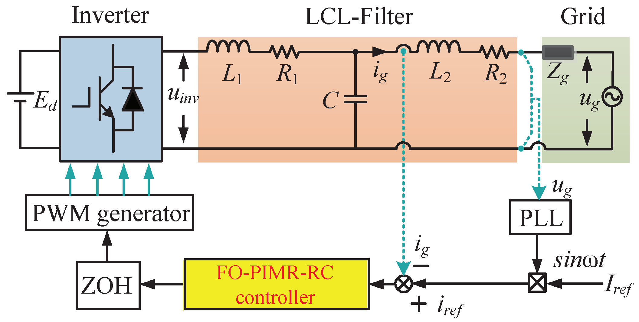
Figure 3 shows the single-phase LCL-type grid-tied inverter structure with the FO-PIMR-RC controller. is the equivalent inductance of the grid, is the output voltage of the inverter, is the reference current, is the grid current, and is the grid voltage. The phase-locked loop (PLL) is used to provide the phase of the . The reference current amplitude is used to form a reference current .
4.2. Design of the FO-PIMR-RC
There are five parameters of the proposed FO-PIMR-RC to be designed: the proportional gain , the internal mode filter , the low-pass filter , the RC gain , and the phase lead compensator .
4.2.1. Proportional Gain
A good proportional gain can enlarge the of the PIMR-type RC, and improve the error convergence speed and low-frequency current harmonics suppression performance. According to [16], is chosen to be 15.
4.2.2. Internal Mode Filter
can be assigned a constant value of less than 1, which reduces the open-loop gain of RC, and results in a weak harmonic suppression capability. Therefore, is selected as the low-pass filter, which can accurately track the low-frequency signal to improve the stability of the system. The expression of is
where . we select .
4.2.3. Low-Pass Filter
In practice, a high-frequency response is more sensitive to parameter changes due to load disturbances or parameter uncertainties. Thus, a low-pass filter is used to further attenuate high-frequency signals to enhance system stability. The Butterworth low-pass filter exhibits the flattest amplitude-frequency characteristics in the passband, therefore, a fifth-order Butterworth low-pass filter is selected. .
4.2.4. RC Gain and Phase Lead Compensator
By selecting an appropriate m in (14), the angle is close to , so that (14) is achieved in a wider frequency band to eliminate more harmonics. Then, the maximum value of can be selected as
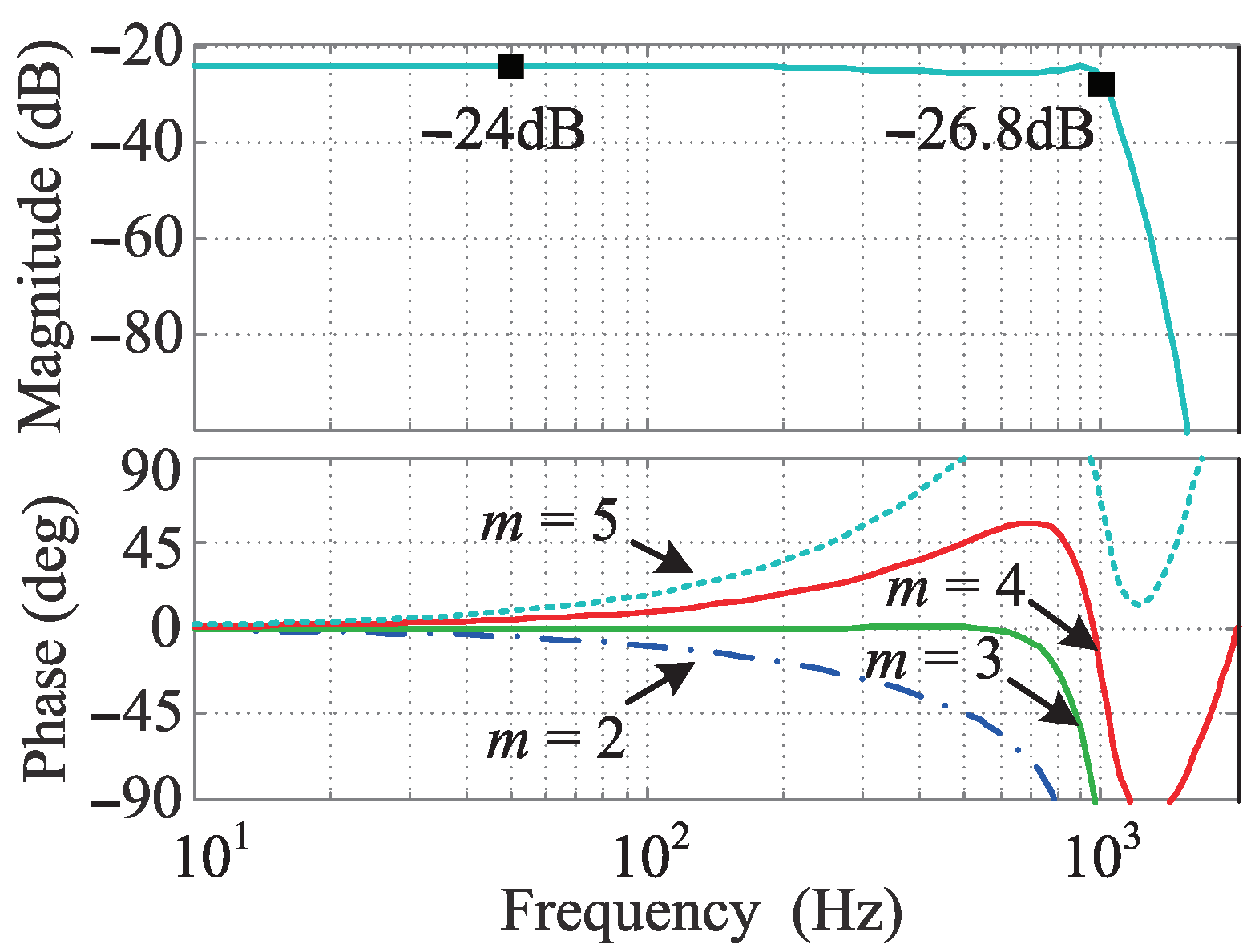
Figure 4 shows the Bode plots of when m has different values. When or , the values of exceed the stable range of . When or , the phase stability range is satisfied. The amplitude-frequency characteristic within the cutoff frequency is between –26.8 dB (0.0457) ∼ –24 dB (0.0631), and . Because the maximum value of is related to m, a suitable m can allow to achieve a larger range, and thus, increase the error convergence speed of the system.
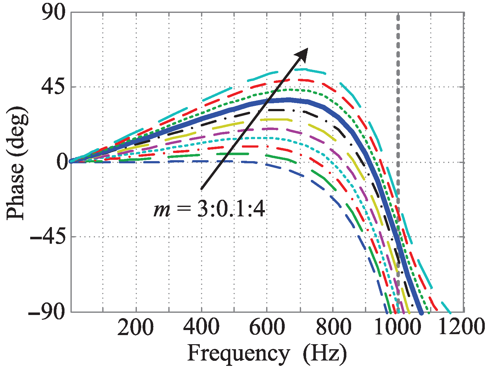
Figure 5 shows that when or , the angle of cannot be the smallest within 1 kHz. If m is a fraction between 3 and 4, then may reach the minimum value. Table 1 shows values when m changes from 3 to 4. The minimum values of with and are 0.568 and 0.66, respectively. According to (19), when and , the maximum values of are 18 and 21, respectively. It can be found that within the bandwidth, when m is a fraction, the value of the RC gain can be enlarged.
4.2.5. Parameter Optimization
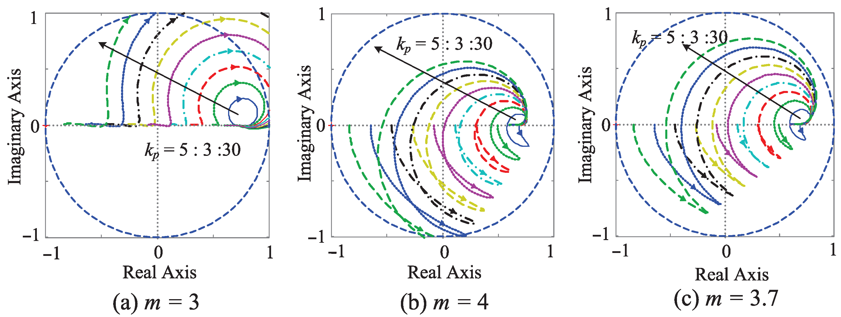
Due to design errors caused by the transition band of the Butterworth low-pass filter, system modeling errors and parameter fluctuation, the RC gain and the phase lead compensator need to be optimized. According to the system stability formula (3), define . Figure 6 shows the trajectories of with , , and , respectively. It can be seen from (a) and (b) that as increases, the trajectory of exceeds the unit circle, and the system destabilizes. It can be seen from Figure 6c that the trajectory is within the unit circle and closer to the center. This implies that when , the system has a larger stability margin and faster convergence speed. Theoretically, a larger control gain can improve the transient response, but will reduce the stability margin. Therefore, in order to ensure the stability of the system, is selected as 16.
5. Simulation Results
MATLAB/Simulink is used to verify the performance of the proposed FO-PIMR-RC at a low sampling frequency (4 kHz). The inverter parameters are shown in Table 2. The controller parameters are as follows: parallel proportional gain , internal mode filter , is the fifth-order Butterworth low-pass filter with a cutoff frequency of 1 kHz, and the phase-lead compensation step , and , respectively.
5.1. Steady-State Performance
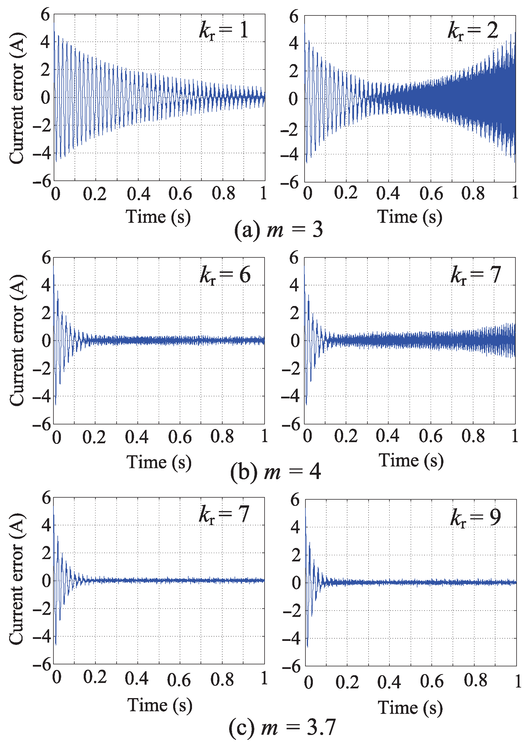
Figure 8 shows the diagrams of current error convergence with different values of m. Figure 8a shows the current error of the PIMR-type RC system with . The error convergence time exceeds 1 second with . The output current error diverges at 0.1 s, and the system will become unstable with . Figure 8b shows the current error of the PIMR-type RC system with . When the system tends to be stable, the steady-state error remains in with . When , the PIMR-type RC output current error starts to diverge at 0.3 s and THD = 7.46%, which is higher than the 5% restriction value of the IEEE 1547 standard. However, the FO-PIMR-RC output current error shown in Figure 8c can converge to steady state at 0.15 s with . When and , the error converges at 0.1 s, and the convergence speed is faster than . It is worth noting that the value of in the simulation results is smaller than the theoretical analysis, because a small can provide a large stability margin to ensure system stability.
From Table 3, It can be seen that at low resolution, the proposed FO-PIMR-RC has larger and lower THD than PIMR-RC.
5.2. Dynamic Performance
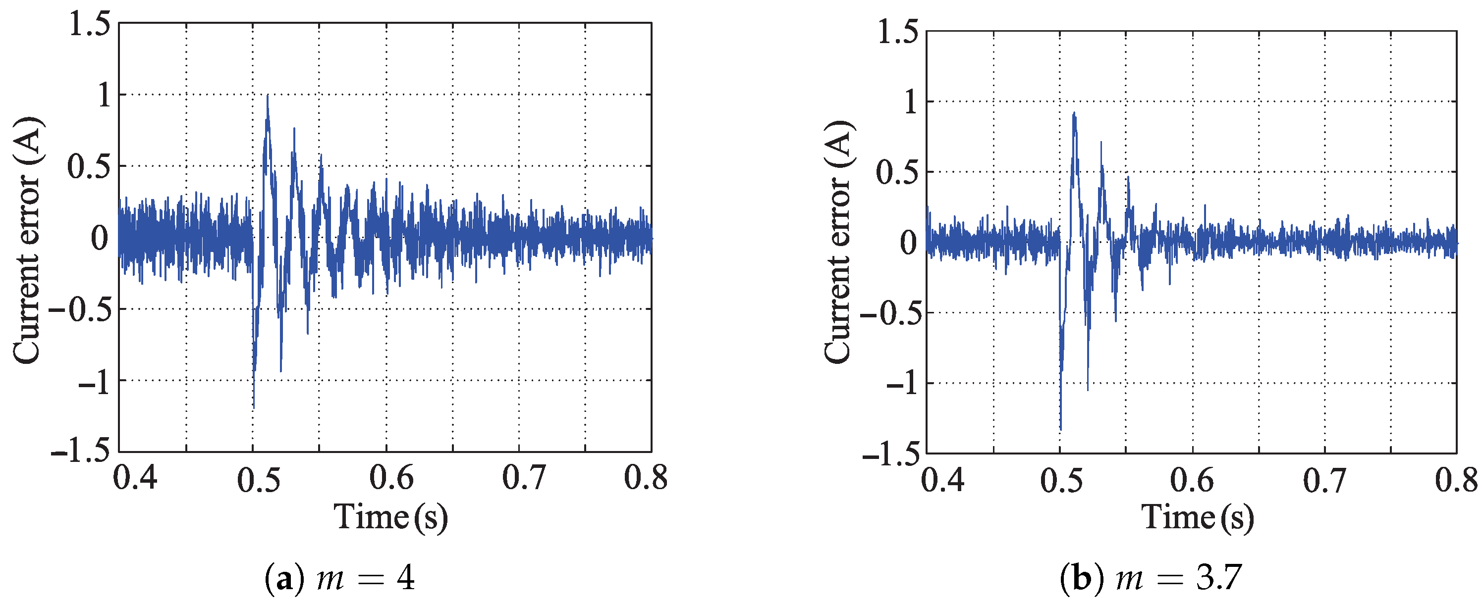
When the magnitude of the reference current is reduced from 10 A to 6 A at 0.5 s, the current dynamic responses of PIMR-type RC (a) and FO-PIMR-RC (b) are shown in Figure 9. It can be found that the current convergence speed of PIMR-RC scheme is 0.15 s and the steady-state error is A. However, the current error convergence speed of FO-PIMR-RC is 0.1 s and the steady-state error is A.
6. Experiment Results
An experimental setup is built to demonstrate the feasibility of the proposed scheme. The experimental setup consists of an inverter setup, a data acquisition board (Quanser QPIDe), a PC with QuaRC and MATLAB/Simulink. The DC bus voltage is generated by a programmable DC power supply (Chroma 62100H-1000) and the sampling/switching frequency is 4 kHz. The inverter parameters are shown in Table 2.
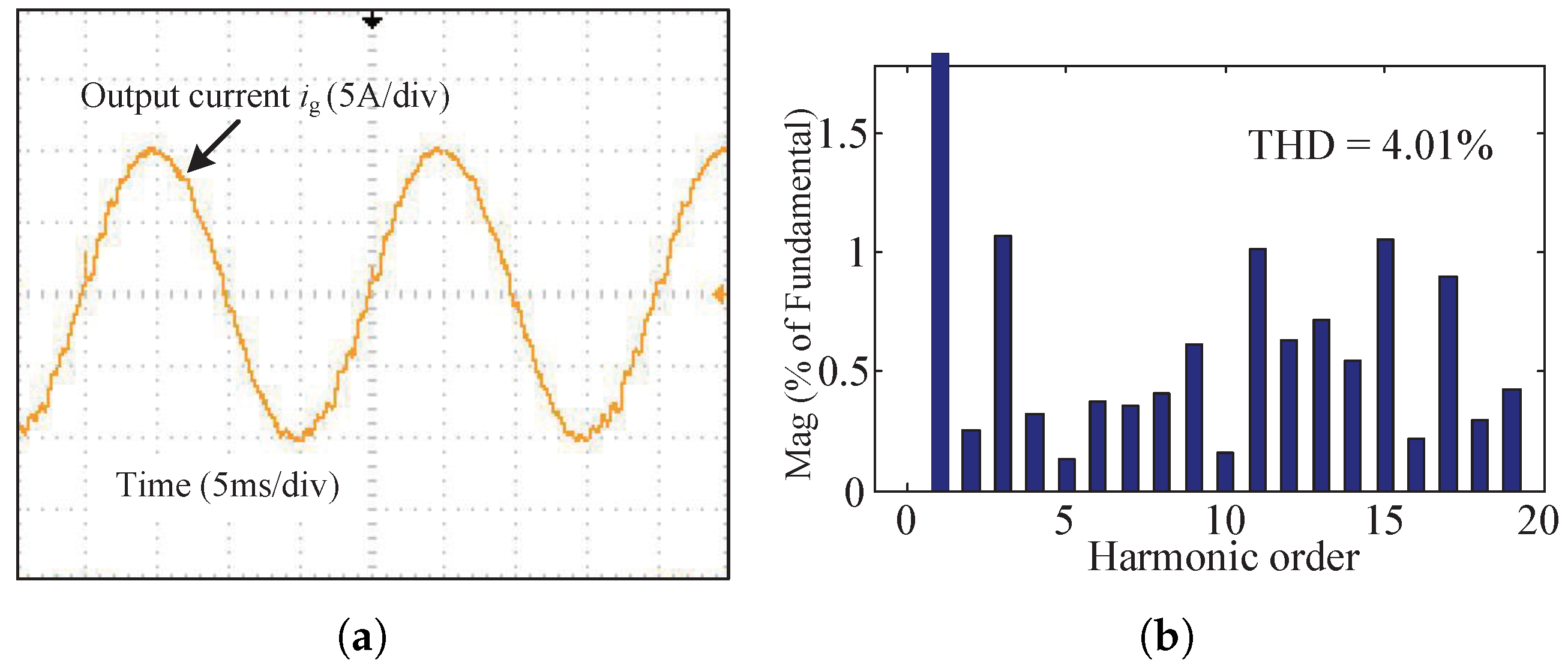
Figure 10 shows the output current waveform and its spectrum analysis of the PIMR-type RC with , . The THD value of the grid current is 4.01%, which is close to the 5% restriction value of IEEE 1547 standard. Since the trajectory of is close to the unit circle in Figure 6a, the low-frequency harmonic content is high.
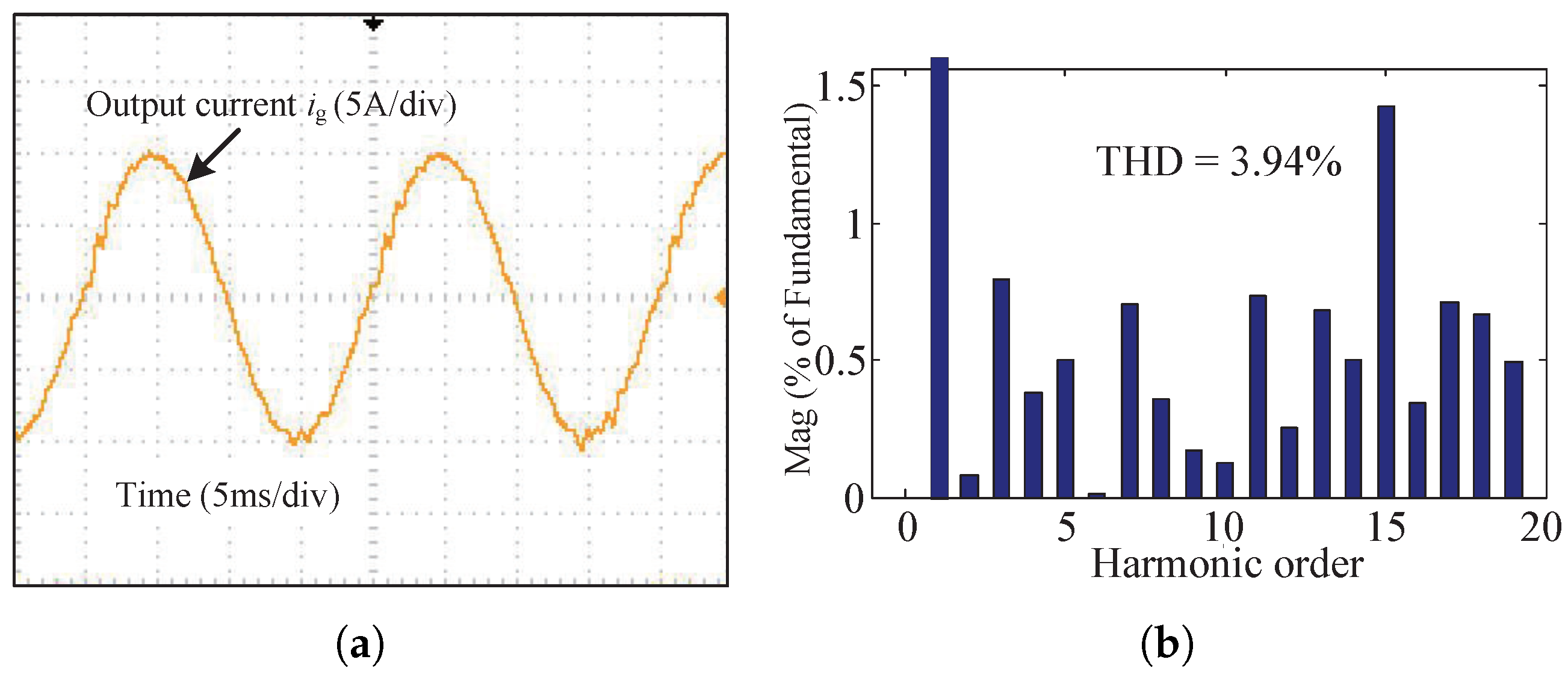
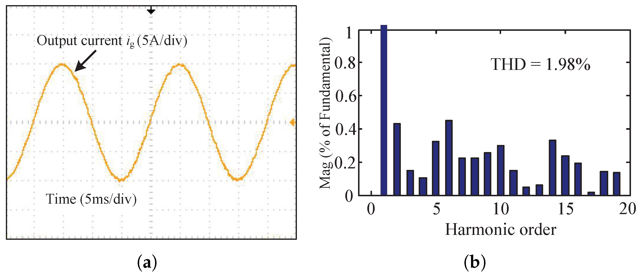
Figure 11 shows the steady-state responses of the PIMR-type RC with , . It can be seen that the output current waveform is distorted, and the THD is 3.94%. Figure 12 shows the steady-state responses of the FO-PIMR-RC with , . The THD value of the output current is 1.98%. For comparison, the 3rd-, 5th-, 7th-, and 9th-order harmonics in Figure 12 are much less than those in Figure 11.
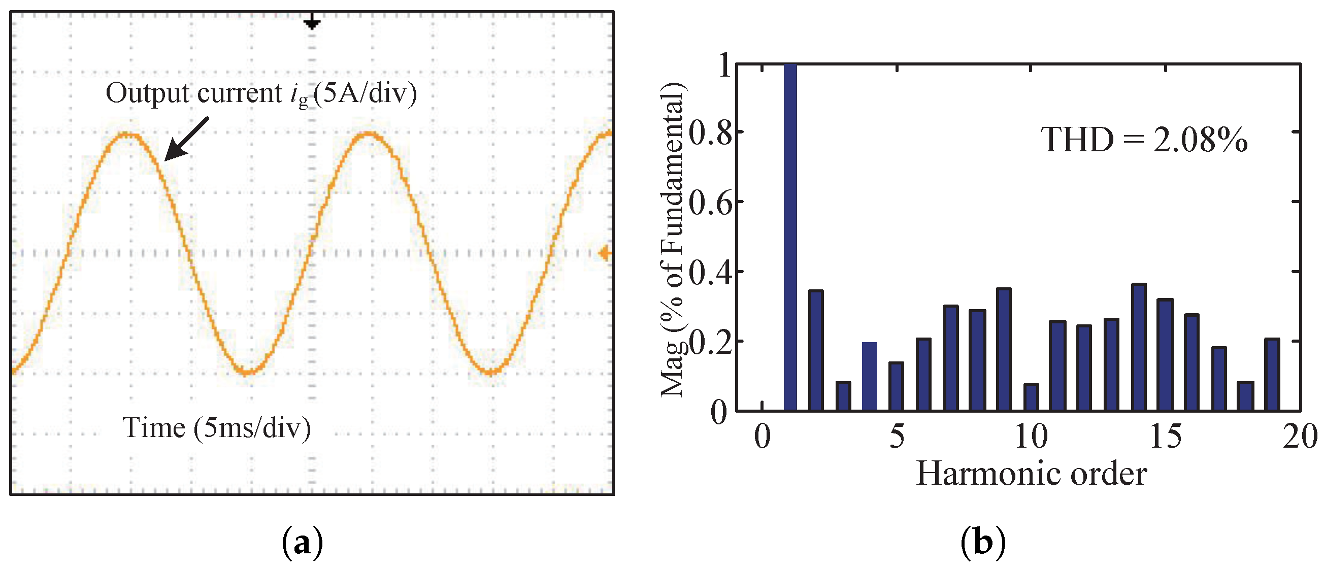
When , , the output current and its spectrum of the FO-PIMR-RC are shown in Figure 13. The THD of the output current is 2.08%, and the single harmonic within 20 order harmonic does not exceed 0.4%.
Comparing Figure 10, Figure 11, Figure 12 and Figure 13, it can be found that the THD values decrease by about 50% by using the FO-PIMR-RC system when the harmonic order is lower than 20, and the current is smoother. The FO-PIMR-RC system exhibits better steady-state performance than the PIMR-type RC system.
7. Conclusions and Discussion
This paper proposes a high-performance FO-PIMR-RC scheme for a grid-tied inverter. The phase-lead compensation step m is extended from an integer to a fraction which can accurately compensate the phase lag. Furthermore, the fractional phase-lead compensator can allow a larger RC gain for the FO-PIMR-RC, reduce the THD of the grid current to 2%, and improve the error convergence speed of the system, which is one-third of the integer order. Simulation and experimental results show that FO-PIMR-RC exhibits the high-performance of low THD, small steady-state error, and fast dynamic response.
The proposed FO-PIMR-RC scheme is not only suitable for suppressing harmonics in high-power wind power grid-tied inverter systems but can also be adopted to three-phase systems, balanced and unbalanced. A three-phase inverter in a stationary coordinate system can be regarded as two isolated single-phase inverters, and the proposed FO-PIMR-RC scheme can be placed into each of these single-phase inverters. Consequently, this can decrease the low-frequency harmonics of three-phase inverters. Moreover, the proposed FO-PIMR-RC scheme can be used in a 400 Hz aircraft medium-frequency power supply with low phase-compensation resolution, where fractional phase-lead compensation is also necessary.
An FIR filter is used to approximate the fractional-order lead compensator of the FO-PIMR-RC in this study. However, the order of the FIR filter is high. Therefore, other approximation methods, such as low-order IIR filters, represent a valuable research topic to be investigated in the future.
Author Contributions
J.Y., Q.Z., H.L., X.Y. and S.W. contributed to conception and design of the study, methodology, J.Y.; simulation, H.L.; validation, J.Y. and Q.Z.; formal analysis, Q.Z.; investigation, J.Y.; resources, H.L.; data curation, X.Y.; writing—original draft preparation, Q.Z.; writing—review and editing, J.Y.; visualization, X.Y.; supervision, H.L.; project administration, S.W.; funding acquisition, J.Y., S.W. and X.Y. All authors have read and agreed to the published version of the manuscript.
Funding
This research was funded by the National Natural Science Foundation (No. 62073297, No. U1813201) and Henan Science and Technology research project (No. 222102520024, No. 222102210019, No. 222102210016).
Institutional Review Board Statement
Not applicable.
Informed Consent Statement
Not applicable.
Data Availability Statement
Not applicable.
Acknowledgments
The authors would like to thank the Henan Province Science and Technology R&D projects, Young Backbone Teachers in Henan Province, and National Natural Science Foundation for their support of this work.
Conflicts of Interest
The authors declare no conflict of interest.
References
- Heydari-doostabad, H.; Monfared, M. An integrated interleaved dual-mode time-sharing inverter for single-phase grid-tied applications. IEEE Trans. Ind. Electron. 2018, 66, 286–296. [Google Scholar] [CrossRef]
- Chen, T.; Lee, C.; Hui, S.Y.R. A General Design Procedure for Multi-Parallel Modular Grid-Tied Inverters System to Prevent Common and Interactive Instability. IEEE Trans. Power Electron. 2019, 34, 6025–6030. [Google Scholar] [CrossRef]
- Pan, D.; Ruan, X.; Wang, X. Direct Realization of Digital Differentiators in Discrete Domain for Active Damping of LCL-Type Grid-Connected Inverter. IEEE Trans. Power Electron. 2018, 33, 8461–8473. [Google Scholar] [CrossRef] [Green Version]
- Yang, Y.; Zhou, K.; Wang, H.; Blaabjerg, F.; Wang, D.; Zhang, B. Frequency Adaptive Selective Harmonic Control for Grid-Connected Inverters. IEEE Trans. Power Electron. 2015, 30, 3912–3924. [Google Scholar] [CrossRef] [Green Version]
- Chen, W.L.; Lin, J.S. One-Dimensional Optimization for Proportional-Resonant Controller Design Against the Change in Source Impedance and Solar Irradiation in PV Systems. IEEE Trans. Ind. Electron. 2014, 61, 1845–1854. [Google Scholar] [CrossRef]
- Ren, L.; Wang, F.; Shi, Y.; Gao, L. Coupling Effect Analysis and Design Principle of Repetitive Control Based Hybrid Controller for SVG With Enhanced Harmonic Current Mitigation. IEEE J. Emerg. Sel. Top. Power Electron. 2022, 4, 1. [Google Scholar] [CrossRef]
- Pereira, L.F.A.; Flores, J.V.; Bonan, G.; Coutinho, D.F.; da Silva, J.M.G. Multiple Resonant Controllers for Uninterruptible Power Supplies-A Systematic Robust Control Design Approach. IEEE Trans. Ind. Electron. 2013, 61, 1528–1538. [Google Scholar] [CrossRef]
- Yang, Y.; Zhou, K.; Blaabjerg, F. Enhancing the Frequency Adaptability of Periodic Current Controllers With a Fixed Sampling Rate for Grid-Connected Power Converters. IEEE Trans. Power Electron. 2016, 31, 7273–7285. [Google Scholar] [CrossRef] [Green Version]
- de Almeida, P.M.; Duarte, J.L.; Ribeiro, P.F.; Barbosa, P.G. Repetitive controller for improving grid-connected photovoltaic systems. IET Power Electron. 2014, 7, 1466–1474. [Google Scholar] [CrossRef] [Green Version]
- Shen, G.; Zhu, X.; Zhang, J.; Xu, D. A New Feedback Method for PR Current Control of LCL-Filter-Based Grid-Connected Inverter. IEEE Trans. Ind. Electron. 2010, 57, 2033–2041. [Google Scholar] [CrossRef]
- Vidal, A.; Freijedo, F.D.; Yepes, A.G.; Fernandez-Comesana, P.; Malvar, J.; López, Ó.; Doval-Gandoy, J. Assessment and Optimization of the Transient Response of Proportional-Resonant Current Controllers for Distributed Power Generation Systems. IEEE Trans. Ind. Electron. 2013, 60, 1367–1383. [Google Scholar] [CrossRef]
- Liserre, M.; Teodorescu, R.; Blaabjerg, F. Multiple harmonics control for three-phase grid converter systems with the use of PI-RES current controller in a rotating frame. IEEE Trans. Power Electron. 2006, 21, 836–841. [Google Scholar] [CrossRef]
- Li, S.; Wang, X.; Yao, Z.; Li, T.; Peng, Z. Circulating Current Suppressing Strategy for MMC-HVDC Based on Nonideal Proportional Resonant Controllers Under Unbalanced Grid Conditions. IEEE Trans. Power Electron. 2015, 30, 387–397. [Google Scholar] [CrossRef]
- Chen, D.; Zhang, J.; Qian, Z. An Improved Repetitive Control Scheme for Grid-Connected Inverter With Frequency-Adaptive Capability. IEEE Trans. Ind. Electron. 2013, 60, 814–823. [Google Scholar] [CrossRef]
- Cho, Y.; Lai, J.S. Digital Plug-In Repetitive Controller for Single-Phase Bridgeless PFC Converters. IEEE Trans. Power Electron. 2013, 28, 165–175. [Google Scholar] [CrossRef]
- Zhao, Q.; Ye, Y. A PIMR-Type Repetitive Control for a Grid-Tied Inverter: Structure, Analysis, and Design. IEEE Trans. Power Electron. 2018, 33, 2730–2739. [Google Scholar] [CrossRef]
- Ye, Y.; Zhou, K.; Zhang, B.; Wang, D.; Wang, J. High-Performance Repetitive Control of PWM DC-AC Converters With Real-Time Phase-Lead FIR Filter. IEEE Trans. Circuits Syst. II Express Briefs 2006, 53, 768–772. [Google Scholar] [CrossRef] [Green Version]
- Zhang, B.; Wang, D.; Zhou, K.; Wang, Y. Linear Phase Lead Compensation Repetitive Control of a CVCF PWM Inverter. IEEE Trans. Ind. Electron. 2008, 55, 1595–1602. [Google Scholar] [CrossRef]
- Zhang, K.; Kang, Y.; Xiong, J.; Chen, J. Direct repetitive control of SPWM inverter for UPS purpose. IEEE Trans. Power Electron. 2003, 18, 784–792. [Google Scholar] [CrossRef]
- Han, B.; Lee, J.S.; Kim, M. Repetitive Controller With Phase-Lead Compensation for Cuk CCM Inverter. IEEE Trans. Ind. Electron. 2017, 65, 2356–2367. [Google Scholar] [CrossRef]
- Arevalo, S.L.; Zanchetta, P.; Wheeler, P.W.; Trentin, A.; Empringham, L. Control and Implementation of a Matrix-Converter-Based AC Ground Power-Supply Unit for Aircraft Servicing. IEEE Trans. Ind. Electron. 2010, 57, 2076–2084. [Google Scholar] [CrossRef]
- Blaabjerg, F.; Liserre, M.; Ma, K. Power Electronics Converters for Wind Turbine Systems. IEEE Trans. Ind. Appl. 2012, 48, 708–719. [Google Scholar] [CrossRef] [Green Version]
- Liu, Z.; Zhang, B.; Zhou, K. Universal Fractional-Order Design of Linear Phase Lead Compensation Multirate Repetitive Control for PWM Inverters. IEEE Trans. Ind. Electron. 2017, 64, 7132–7140. [Google Scholar] [CrossRef] [Green Version]
- Ye, Y.; Wu, Y.; Xu, G.; Zhang, B. Cyclic Repetitive Control of CVCF PWM DC-AC Converters. IEEE Trans. Ind. Electron. 2017, 64, 9399–9409. [Google Scholar] [CrossRef]
- Zhang, B.; Zhou, K.; Wang, D. Multirate Repetitive Control for PWM DC/AC Converters. IEEE Trans. Ind. Electron. 2014, 61, 2883–2890. [Google Scholar] [CrossRef]
- Zhao, Q.; Ye, Y. Fractional Phase Lead Compensation RC for an Inverter: Analysis, Design, and Verification. IEEE Trans. Ind. Electron. 2017, 64, 3127–3136. [Google Scholar] [CrossRef]
- Dannehl, J.; Wessels, C.; Fuchs, F.W. Limitations of Voltage-Oriented PI Current Control of Grid-Connected PWM Rectifiers With LCL Filters. IEEE Trans. Ind. Electron. 2009, 56, 380–388. [Google Scholar] [CrossRef]
- Ye, Y.; Xu, G.; Wu, Y.; Zhao, Q. Optimized Switching Repetitive Control of CVCF PWM Inverters. IEEE Trans. Power Electron. 2018, 33, 6238–6247. [Google Scholar] [CrossRef]
- Zou, Z.X.; Zhou, K.; Wang, Z.; Cheng, M. Frequency-Adaptive Fractional-Order Repetitive Control of Shunt Active Power Filters. IEEE Trans. Ind. Electron. 2015, 62, 1659–1668. [Google Scholar] [CrossRef]
- Chen, S.; Zhao, Q.; Wang, X.; Wang, D.; Lu, X. Fractional Phase Lead Compensation for PIMR-type Repetitive Control on a Grid-tied Inverter. In Proceedings of the 2019 IEEE Innovative Smart Grid Technologies—Asia (ISGT Asia), Chengdu, China, 21–24 May 2019; pp. 2357–2361. [Google Scholar] [CrossRef]
- Oetken, G. A new approach for the design of digital interpolating filters. IEEE Trans. Acoust. Speech Signal Process. 1979, 27, 637–643. [Google Scholar] [CrossRef]
- Ye, J.; Liu, L.; Xu, J.; Shen, A. Frequency Adaptive Proportional-Repetitive Control for Grid-Connected Inverters. IEEE Trans. Ind. Electron. 2020, 68, 7965–7974. [Google Scholar] [CrossRef]
Figure 1.
Control scheme of the PIMR-type RC.

Figure 2.
Structure of the FO-PIMR-RC with fractional-order phase lead compensation.

Figure 3.
Single-phase LCL-type grid-tied inverter structure with FO-PIMR-RC controller.

Figure 4.
Bode plots of when m holds different values.

Figure 5.
phases when m changes from 3 to 4.

Figure 6.
Trajectories of when (a) , (b) , and (c) , respectively.

Figure 7.
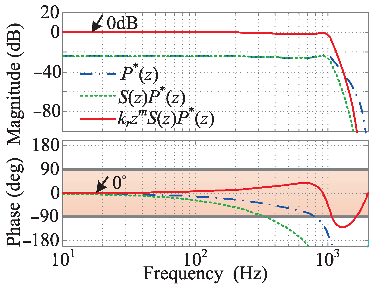
Bode diagrams of , , and .

Figure 8.
Diagrams of current error convergence with different values of m: (a) , (b) , (c) .

Figure 9.
Control system output current error when (a) m = 4 and (b) m = 3.7, respectively, (from 10 A to 6 A).
Figure 9.
Control system output current error when (a) m = 4 and (b) m = 3.7, respectively, (from 10 A to 6 A).

Figure 10.
PIMR-type RC () control system with : (a) The output current waveform; (b) The output current spectrum analysis.
Figure 10.
PIMR-type RC () control system with : (a) The output current waveform; (b) The output current spectrum analysis.

Figure 11.
PIMR-type RC () control system with : (a) The output current waveform; (b) The output current spectrum analysis.
Figure 11.
PIMR-type RC () control system with : (a) The output current waveform; (b) The output current spectrum analysis.

Figure 12.
FO-PIMR-RC () control system with : (a) The output current waveform; (b) The output current spectrum analysis.
Figure 12.
FO-PIMR-RC () control system with : (a) The output current waveform; (b) The output current spectrum analysis.

Figure 13.
FO-PIMR-RC () control system with : (a) The output current waveform; (b) The output current spectrum analysis.
Figure 13.
FO-PIMR-RC () control system with : (a) The output current waveform; (b) The output current spectrum analysis.


Table 1.
Values of when m changes from 3 to 4 within the cutoff frequency of 1 kHz.
| m | Range of Angle () | |
|---|---|---|
| 3 | ||
| 3.1 | ||
| 3.2 | ||
| 3.3 | ||
| 3.4 | ||
| 3.5 | ||
| 3.6 | ||
| 3.7 | ||
| 3.8 | ||
| 3.9 | ||
| 4 |
Table 2.
Parameters of the FO-PIMR-RC.
| Parameters | Value |
|---|---|
| Inverter side inductance: | 3 mH |
| equivalent resistance: | 0.48 Ω |
| Grid side inductance: | 2.6 mH |
| equivalent resistance: | 0.32 Ω |
| Filter capacitor: C | 10 F |
| DC bus voltage: | 380 V |
| Grid rated frequency: | 50 Hz |
| Sampling frequency: | 4 kHz |
| Switching frequency: | 4 kHz |
| Switch dead time: | 3 s |
Table 3.
Comparison of , and under difference .
| THD (%) | |||||||||
|---|---|---|---|---|---|---|---|---|---|
| 1 | 2 | 3 | 4 | 5 | 6 | 7 | 8 | 9 | |
| 3.28 | |||||||||
| 2.17 | 1.97 | 1.93 | 1.93 | 1.98 | 2.24 | ||||
| 2.07 | 1.92 | 1.90 | 1.98 | 1.86 | 1.89 | 1.98 | 1.92 | 1.90 | |
Publisher’s Note: MDPI stays neutral with regard to jurisdictional claims in published maps and institutional affiliations. |
© 2022 by the authors. Licensee MDPI, Basel, Switzerland. This article is an open access article distributed under the terms and conditions of the Creative Commons Attribution (CC BY) license (https://creativecommons.org/licenses/by/4.0/).
Share and Cite
MDPI and ACS Style
Yu, J.; Zhao, Q.; Li, H.; Yue, X.; Wen, S. High-Performance Fractional Order PIMR-Type Repetitive Control for a Grid-Tied Inverter. Energies 2022, 15, 3854. https://0-doi-org.brum.beds.ac.uk/10.3390/en15113854
AMA Style
Yu J, Zhao Q, Li H, Yue X, Wen S. High-Performance Fractional Order PIMR-Type Repetitive Control for a Grid-Tied Inverter. Energies. 2022; 15(11):3854. https://0-doi-org.brum.beds.ac.uk/10.3390/en15113854
Chicago/Turabian StyleYu, Jun, Qiangsong Zhao, Hengyi Li, Xuebin Yue, and Shengjun Wen. 2022. "High-Performance Fractional Order PIMR-Type Repetitive Control for a Grid-Tied Inverter" Energies 15, no. 11: 3854. https://0-doi-org.brum.beds.ac.uk/10.3390/en15113854
Note that from the first issue of 2016, this journal uses article numbers instead of page numbers. See further details here.