
Regression-Analysis-Based Empirical Correlations to Design Regenerative Flow Machines
by
 , , and
Feroskhan M.
1 ,
,
Sreekanth M.
1,2,* ,
,
Karunamurthy K.
1,
Sivakumar R.
1,
Nazaruddin Sinaga
3 and
and
T. M. Yunus Khan
4 1
School of Mechanical Engineering, Vellore Institute of Technology Chennai, Chennai 600127, India
2
Electric Vehicles Incubation Testing and Research Centre, Vellore Institute of Technology Chennai, Chennai 600127, India
3
Mechanical Engineering Department, Engineering Faculty, Diponegoro University, Semarang 50275, Indonesia
4
Department of Mechanical Engineering, College of Engineering, King Khalid University, Abha 61421, Saudi Arabia
*
Author to whom correspondence should be addressed.
Energies 2022, 15(11), 3861; https://0-doi-org.brum.beds.ac.uk/10.3390/en15113861
Submission received: 7 April 2022
/
Revised: 11 May 2022
/
Accepted: 16 May 2022
/
Published: 24 May 2022
Abstract
:Regenerative flow machines are known to be simple in construction but complex in flow characteristics. Due to this reason, the design of these machines has been primarily esoteric, and hence its performance heavily relies on the experience and expertise of the designer. Since there are no established rules of thumb for designing them, this paper attempts to provide simple design correlations for systematically designing regenerative flow machines viz. pumps, blowers, and compressors. Three different impeller designs have been considered, namely the (i) single-side vane impeller, (ii) double-side vane impeller, and (iii) peripheral vane impeller, for the three types of machines. More than ten design parameters have been considered for sizing the machines. Experimental and computational data available in open literature have been used to obtain physically meaningful correlations in simple form, and require minimal and practically available inputs. Fluid properties and practical constraints were taken into consideration while deriving the correlations. Constants in the correlations were obtained using least square regression analysis. The accuracy of the obtained correlation is determined by the correlation coefficient. The deviation obtained using the derived correlations varied from 10 to 25%. A consolidated set of correlations has been presented, which will be helpful in making a preliminary design before CFD simulation, design optimization, and prototype building. Finally, the obtained correlations have been used to demonstrate the design of a regenerative flow pump.
1. Introduction
Regenerative flow machines (pumps, blowers, and compressors) provide a high-pressure rise in a single stage compared to their centrifugal counterparts [1]. They also develop high pressure at low flow rates, typical of positive displacement machines [2]. Additionally, with simple construction, a low specific speed, self-priming ability, stable operation, and low manufacture cost [3], regenerative flow machines are attractive despite their poor efficiency [4]. For these reasons, these machines are considered for niche applications such as hydrogen circulation in fuel cell systems, where space is a constraint and efficiency takes a lower priority [5].
Even though regenerative flow machines (RFM) have been known for over a century, their applications have been limited. The number of research articles published in this field is less than other types of roto-dynamic turbomachines [6]. This condition leaves vast scope for further studies to understand the rotor and fluid’s flow pattern and momentum exchange. In addition, it reduces the losses, improves efficiency, and optimizes the design parameters, degradation effects due to erosion, cavitation, and stress build-up [3,7]. Few research groups have recently published their results on these machines. Quail et al. [4,8,9,10,11,12] focused on regenerative flow pumps (RFP) and carried out experimental and computational studies to evaluate the performance. They also produced impellers using rapid prototyping methods using different materials. Badami [13] and Badami and Mura [1,5,14,15] have focused on blower applications handling hydrogen for fuel cell application and have carried out extensive experiments and simulations. Raheel, along with Engeda, have studied regenerative flow compressors and pumps for micro-turbine and automotive applications [16,17,18,19,20,21]. Raheel [16], in his dissertation, studied pumps and compressors for specific applications, such as micro-turbines and fuel pumps of automobile applications. Song et al. [17] presented a flow theory for pumps that discusses an innovative flow mechanism. Raheel and Engeda [18] and Raheel et al. [19] proposed a design process for regenerative flow machines with radial vanes. These are some of the very few works that mention the design procedure. They found that, as the inlet pressure is increased, the pressure ratio drops but the efficiency increases. Engeda [20] extended the then existing knowledge from the developed flow region to the developing region. Raheel and Engeda [21] presented a review of the research status of regenerative flow compressors and pumps. Nejad et al. [6] studied methods of improving the performance of regenerative pumps by modifying the geometric parameters of vane and casing. They found that a better efficiency can be obtained by increasing the arc of admission. Nejadrajabali et al. [22] studied the flow pattern and influence on efficiency by varying the blade geometry. They considered symmetric as well as asymmetric vanes. Nejadali [23] presented an easy and novel method to compute flow in a pump with a bucket shape vane. Nejad et al. [24] conducted experiments and found out the best vane angle (10°) for a pump. Studies have also been conducted to study the influence of fluid viscosity on the performance of a pump [25]. They altered the viscosity of water by mixing polyacrylamide in it.
In the brief literature presented above, it can be seen that studies on RFMs have been carried out to understand the influence of design parameters and fluid properties on performance. Other studies have also been carried out to understand the flow pattern and what brings about the ‘regeneration’ to improve efficiency. Both experimental and computational methods have been adopted. For a practicing engineer who sets out to design an RFM using simple correlations and thumb rules, there is very little help from the literature. Unlike the design handbooks available for commonly used centrifugal pumps, blowers, and compressors, none are available for RFM.
Moreover, the studies mentioned above have been carried out on non-commercial machines. The impellers type, size, casing design, and other geometric parameters have been designed using empirical knowledge and rules of thumb, which are esoteric and scarcely available in the open literature. A small number of cases available in the open literature are described below. Raheel and Engeda [18] have provided a systematic design procedure of a radial blade (peripheral vane) machine using correlations and typical ranges of magnitudes of various design parameters. Hollenberg and Potter [26] have given a correlation for torque as a function of head and flow coefficients. Nejad et al. [24] have correlated the hydraulic efficiency and vane angle. Apart from these three articles available in the open literature, the present authors have not found any other source of correlations.
From the above literature survey, it is understood that empirical design correlations for RFMs are scarce. There is a strong need for design correlations for RFMs to aid the practicing design engineer. These correlations could help to make an initial informed design that simulations and subsequent experimentation can further improve. Hence, this work aims to provide correlations for significant design parameters for the three RFMs, namely pumps, blowers, and compressors. The correlations will be developed by extracting data from available experimental and computational literature related to RFM. The design parameters are the impeller diameter, number of vanes, vane inlet/outlet angles, vane bending angle, vane symmetricity, vane suction side angle, vane thickness, side-channel area, stripper angle, vane shape, axial clearance, rotational speed, and influence of fluid properties, such as density and viscosity. A group of non-dimensional parameters aid in generalizing the correlations and make them applicable for a wider range of operating conditions. Wherever possible, non-dimensional parameters will be used to minimize the number of variables in the correlation and generalize it. The nature of the correlation is based on physics suggested by dimensional analysis, and the constants in the correlation are chosen based on the best correlation coefficient.
It is clear that there is no simple design procedure available in open literature for regenerative flow machines even though they existed for over a century. With the advent of high speed computers, simulations can be carried out before building a prototype. However, the simulations need a preliminary design to begin with and this work aims at providing simple equations/correlations which can be used to make an initial design to start simulations. The novelty of this work lies in the fact that such a consolidated set of correlations are not available in the literature and this work fills that gap.
2. Methodology Adopted for the Present Study
There are a considerable number of experimental and computational studies reported on RFM. An objective literature study indicates that a wide range of operating parameters has been used in the studies. For carrying out the present work, the design and operational parameters were obtained from the results of all of the available articles. The machines were classified based on the type (vanes located on one side, both sides, on the periphery) and application (pump, blower, and compressor). For each type and application, the critical data (indicated in the next section) were used to correlate the design and operating parameters. The terms in the correlation were obtained from the dimensional analysis [27] or physical intuition. Once the terms were finalized, a correlation relating to the terms was obtained using the least-square regression analysis method. Among the several correlations obtained, those with the highest correlation coefficient were proposed in this work. In a few cases, if the correlation with the best correlation coefficient has several (more than five) independent variables, the best correlation was proposed.
The features of the present work include:
- Deriving and presenting simple and easy-to-use design correlations.
- The data necessary for deriving the correlations were digitally extracted from the available literature. At least 30 data points were used for a particular design.
- For simplicity, the number of constants in each correlation was kept below five.
- Wherever multiple correlations are possible, the one reflecting the physics and also having the highest correlation coefficient, but not less than 0.8, was proposed.
- Non-dimensional parameters were used wherever possible.
- A step-by-step design procedure is demonstrated in Appendix A.
A general procedure for obtaining the correlation using least square regression was adopted, as suggested by Holman [28], and is shown below. If x1 and x2 are independent variables and y is a dependent variable, a relation between them can be obtained as shown below in Equation (1):
where b, m1, and m2 are constants to be determined using the least squares regression method. S is the sum of the squares of the difference between measured and computed values of the dependent variable y.
y = b + m1x1 + m2x2
The value of S can be minimized by carrying out partial differentiation with respect to b, m1, and m2 as shown below.
Values of b, m1, and m2 can be obtained by solving Equation (3). For a different set of dependent and independent variables, a different form of correlation could be apt, for which, Equations (2) and (3) can be different. Using the above method, different design correlations were derived for different types of impellers (one-side vane, double-side vane, and peripheral vane impellers) and different types of machines (pumps, blowers and compressors). This is necessary to derive accurate correlations for a specific application.
3. Results and Discussion
The most crucial function in an RFM under consideration is pressure build-up followed by flow rate. The sizing and other design and operating parameters will be tuned in such a way as to attain the desired pressure rise. Hence, the design and operating parameters should function the exit pressure, pressure rise, or pressure ratio. This section will discuss various design parameters, and correlations will be presented below. In most of the published literature in this field, a significant result is the pressure rise against flow rate, with various other variables, such as rotational speed, axial clearance, vane angles, and vane shape, as independent variables. According to Cimbala and Yunus [27] and Dubey et al. [29], pressure rise is a function of the volumetric flow rate, impeller diameter, rotational speed, density, and viscosity of the fluid, and the blade surface roughness. Since there are several independent variables, they [27,29] employed the Buckingham Pi theorem to obtain a relation between the non-dimensional terms. The basic non-dimensional terms are the pressure coefficient (ψ), flow coefficient (Φ), and a term similar to Reynold’s number. Several authors who reported studies in this field chose to present their results in these non-dimensional parameters. Very few authors reported in dimensional quantities, i.e., pressure rise (ΔP) vs. flow rate (Q). The pressure coefficient is a measure of the pressure build up ability, the flow coefficient is a measure of the flow rate, and Reynolds number is an indicator of the rotational speed. Therefore, in the present work, this important result is used to derive correlations between the key design and operating parameters.
Pressure and flow coefficients are represented in different non-dimensional forms as shown below:
The most common representation is the one shown in Equation (4). The present work also uses this representation. In literature, wherever forms shown in Equations (5) and (6) are encountered, they have been suitably converted to Equation (4) and used in this work.
3.1. Single-Side Vane Impeller Machines
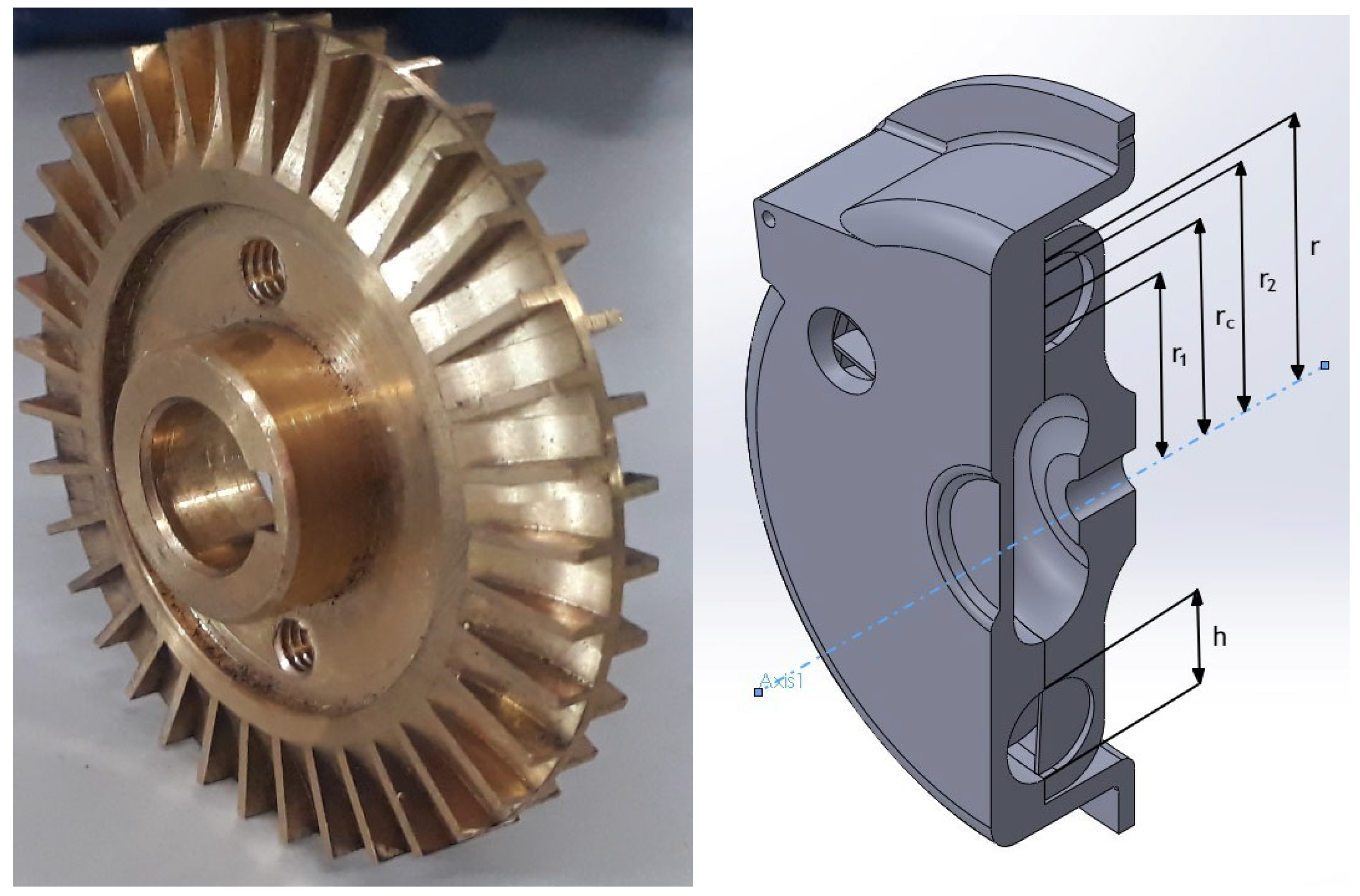
For a detailed and schematic description of the design parameters, the reader can refer to Badami and Mura [1]. Figure 1 below shows a double-side vane impeller (discussed in Section 3.2) of an RFP. If there are vanes on only one side, it would be a single-side vane impeller. Some important dimensions are also shown.
Impeller Diameter (d)
The pressure coefficient (ψ), flow coefficient (ϕ), and rotational speed (N) can be related according to the correlation form:
ψ = aNbcϕ
In the correlation, a, b, and c are constants that need to be determined using regression analysis. On substituting Equation (4), and considering that maximum pressure (which is also the rated pressure of the machine) is obtained at a zero flow rate (or zero value of flow coefficient), the impeller diameter can be written as:
Hence, the impeller diameter can be computed if the desired pressure ratio and the impeller speed (which is determined by the driving motor and the gear ratio and usually lies between 1500 and 3000 rpm) are known, and values of the constants ‘a’ and ‘b’ are estimated.
- a.
- ψ–ϕ correlation for pumps with one-side vane impeller
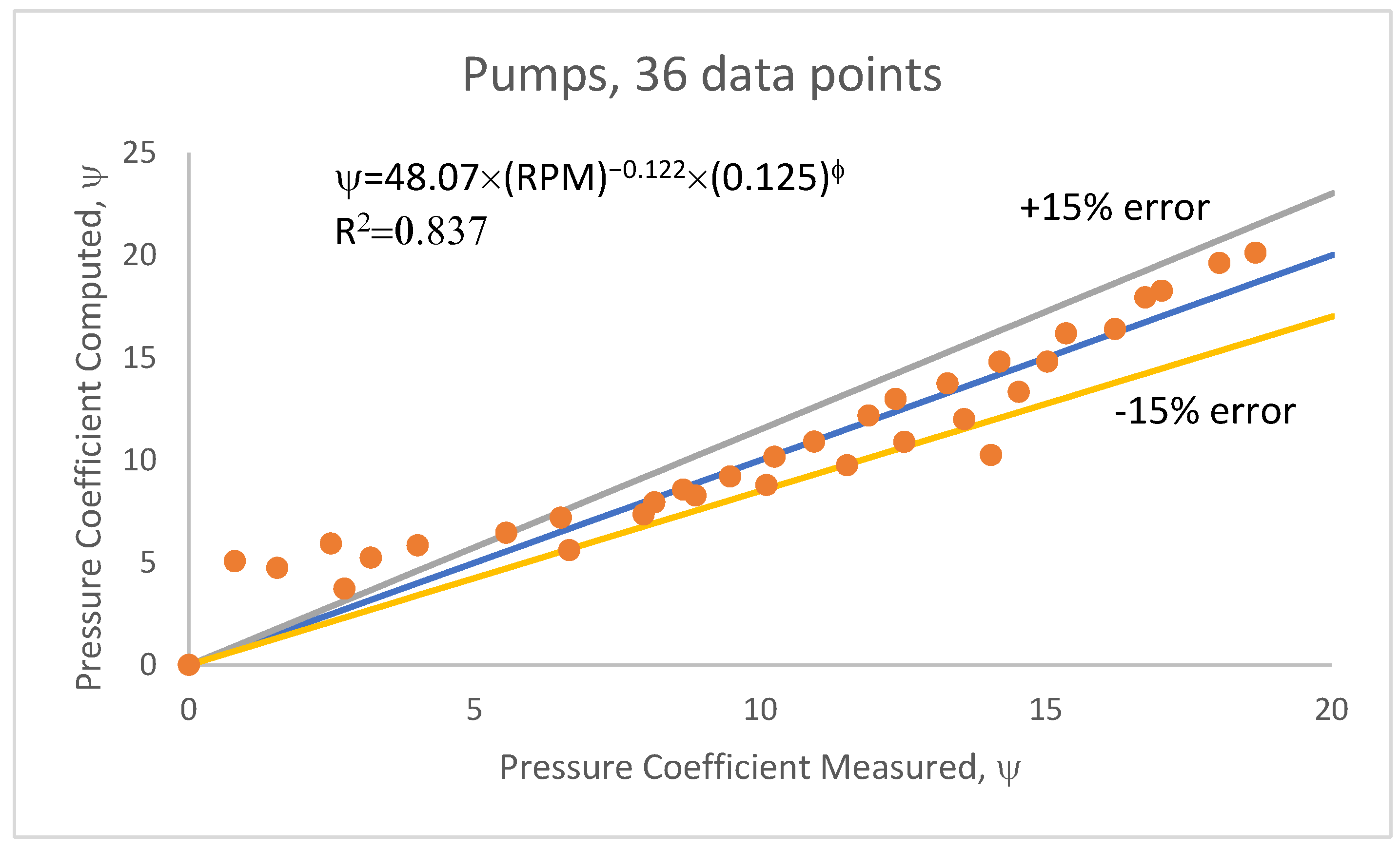
Nejad et al. [6], Meakhail and Park [30], and Pei et al. [31] have reported the performance of pumps as a function of RPM. The rotational speed ranged between 1200 to 1500 rpm, and a correlation has been derived using 36 data points from these three works for three different pumps. The correlation is in the form of Equation (7) and is given below:
Figure 2 compares the measured and computed (using the correlation) pressure coefficient values. More than 80% of the data fall with an error of ±15%, and the correlation coefficient is 0.837.
- ψ–ϕ correlation for blowers with one-side vane impeller
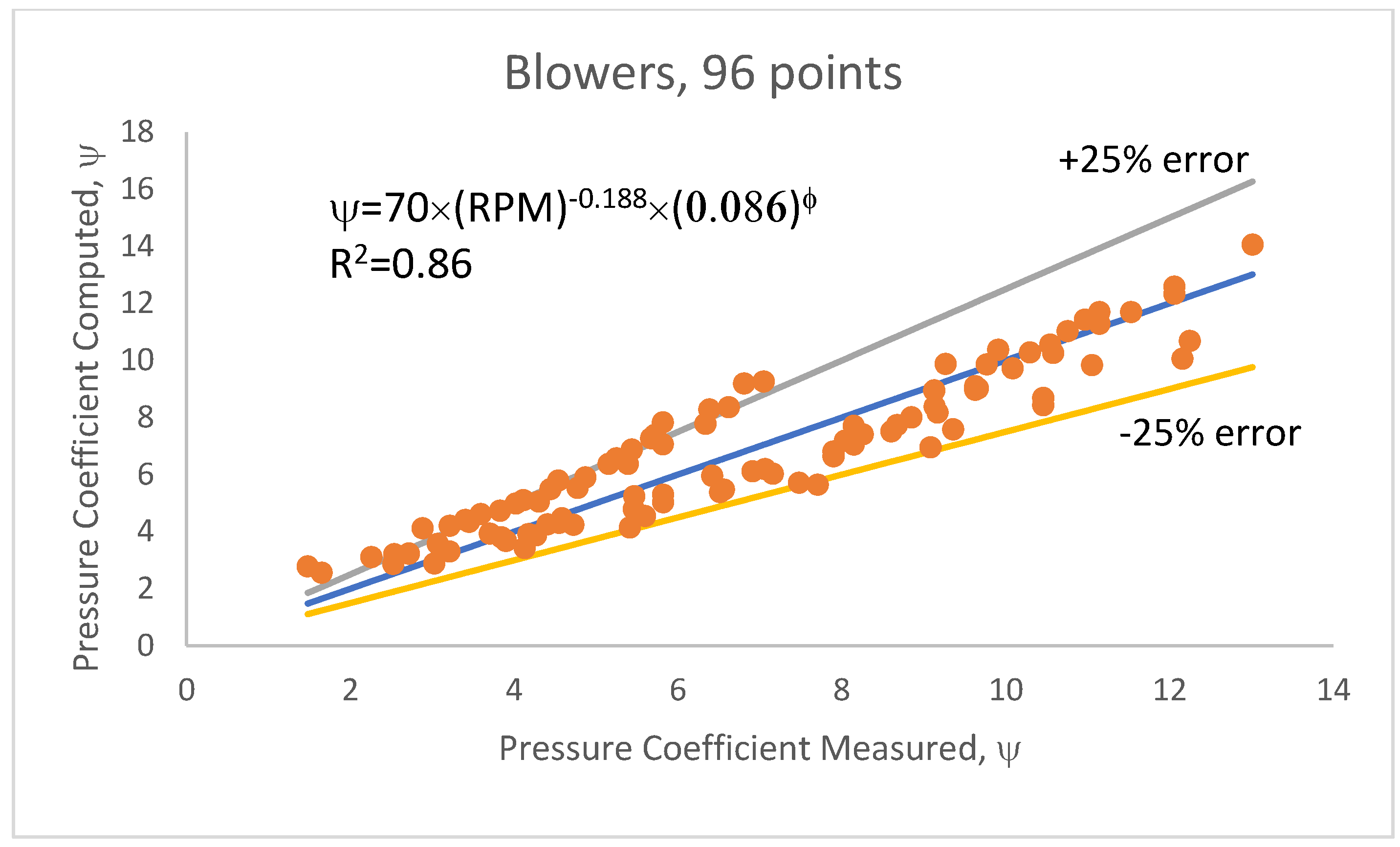
In this study, blowers are considered to develop a pressure ratio of 1.09 or less. A machine producing a pressure ratio above 1.09 is termed a compressor. Badami and Mura [1,5,15] have reported the conducted studies on hydrogen for fuel cell applications and presented performance results as a rotational speed function, ranging from 5000 to 25,000 rpm. The data are from three different blowers at six different speeds. The ψ–ϕ correlation is given below in Equation (10).
The measured and computed values of the pressure coefficient are shown in Figure 3. Close to 100 points have been used to obtain the correlation, and the computed values deviate from the measured ones by a maximum of ±25%. In addition, the correlation coefficient is 0.86. Around 10% of the data points are outside the 25% error limit.
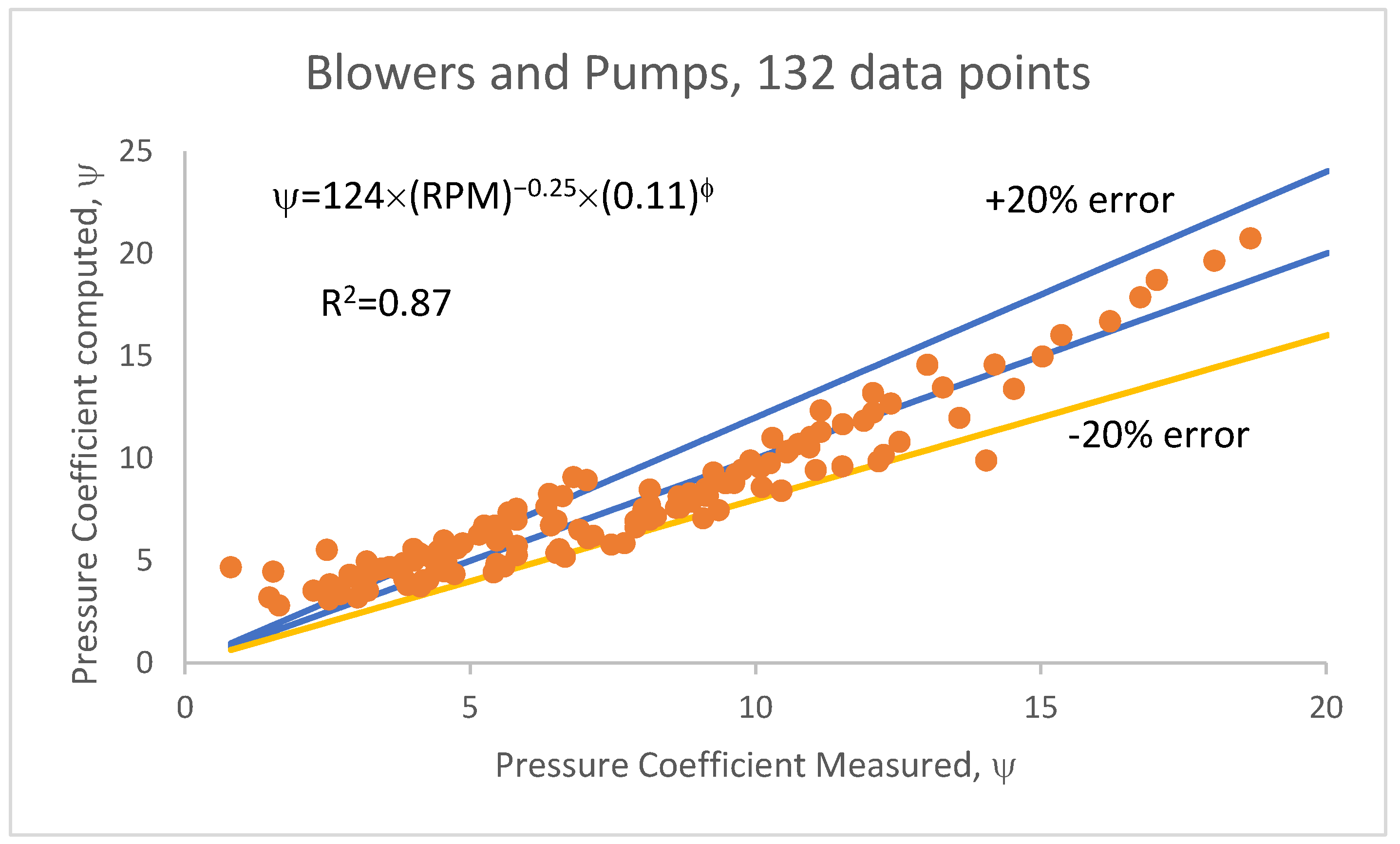
From Equations (9) and (10), it can be seen that the rotational speed weakly and inversely influences the pressure coefficient. Figure 4 shows the consolidated data of both pumps and blowers using a common correlation given in Equation (11).
Figure 4 compares the measured and computed pressure coefficient for all the data of a single-side vane impeller, including pumps and blowers incorporating data of six different machines at eight different speeds. Most of the data fall with an error of ±20%, while 18% of this correlation has an error beyond +20%.
It is to be noted that no work reported the performance of compressors with a single-side vane impeller.
- b.
- Hydraulic efficiency (η)–flow coefficient (ϕ) relation
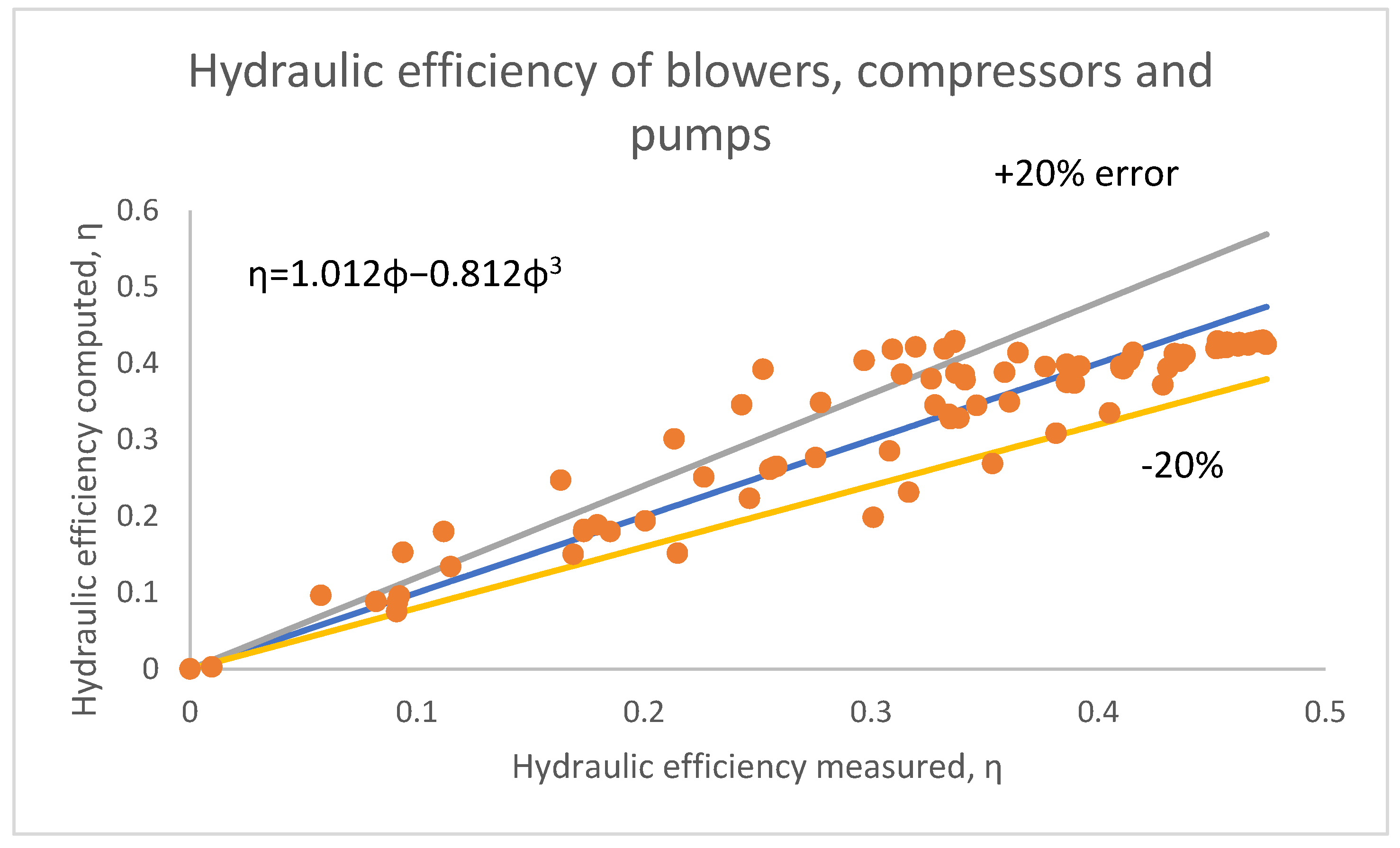
Equations (9)–(11) require an input of flow coefficient. Several researchers, such as Badami and Mura [1,5,15], Nejad et al. [6], and Meakhail and Park [30], have reported the hydraulic efficiency (ratio of potential energy imparted to the fluid and the rotational energy supplied to the impeller shaft, QΔP/τω) versus flow coefficient data for blowers and pumps, respectively, altogether are five different machines. Interestingly, it can be seen that the rotational speed does not influence the efficiency whereas the axial clearance showed a considerable influence, and the efficiency was maximum for the least clearance. This is due to the reduction in leakage losses at a low clearance. Figure 5 shows the correlation that fits the η-φ data. A practically simple correlation (Equation (12)) is good enough to estimate the efficiency for a given flow coefficient.
In this equation, 90% of the data fit within an error of ±20%. The maximum efficiency can be estimated by differentiating Equation (12) from the flow coefficient and equating the derivative to zero. This indicates that the maximum efficiency would be achieved at a flow coefficient of 0.43. In addition, the maximum efficiency would be 41%.
- c.
- Axial clearance (G)
Among the one-side vane impeller machines, only Badami and Mura [5] studied the influence of axial clearance on the performance. They carried studies on a blower handling hydrogen and found that a lower axial clearance (in the range of 0.2–0.5 mm) results in a higher pressure coefficient. Since the pressure coefficient is a function of the flow coefficient and rotational speed, a correlation with all three independent variables has been derived and is shown below.
In the entire literature, the axial clearance has been chosen to fall in a narrow range of 0.1 to 0.9 mm. Hence, this parameter can be chosen based on the manufacturing tolerances rather than the correlation.
- d.
- Stripper Angle (θs)
Badami and Mura [1,5,15] consistently used a stripper angle of 340°. The only study that considered the influence of the stripper angle is Pei et al. [31]. They studied three angles, namely 345°, 330°, and 315°, and found that 345° gives the highest amount of pressure rise and that there is minimal influence on the efficiency. Theoretically, the stripper angle should be 360° to provide maximum regenerations. However, to locate the position and size of the inlet and outlet ports, it must be less than 360°. Hence, the maximum practically proper stripper angle will serve the purpose, and, according to the literature [3], a choice in the range of 340°–345° would be safe.
- e.
- Mean side-channel radius (rs)
Badami and Mura [1,5,15] used a side-channel radius of 57 mm, whereas Pei et al. [31] used 58 mm. The ratio of the side-channel radius to the impeller radius ranges from 0.77 to 0.82. Hence, the side-channel radius can be sized according to:
- f.
- Vane (blade) height (bh)
In the literature [7], the vane height ranged from 24 to 35 mm. The vane height has a proportionality to the impeller diameter. The correlation given in Equation 15 can compute the vane height across all one-side vane impeller machines.
where d is in mm.
- a.
- Vane thickness (bt)
The vane thickness is generally governed by stress conditions, especially those induced by the rotation. Hence, it is determined by the rotational speed, where the higher speeds need the thicker vanes. Pumps that operate at lower speeds (1500 rpm) have been designed with 2 mm thick vanes, whereas blowers operating at higher speeds (>5000 rpm) have been designed with 6–8 mm vanes. The correlation shown in Equation (16) can be used to compute the vane thickness. However, the thickness also depends on the impeller/vane material type.
- b.
- Number of vanes (z)
The number of vanes needs to be chosen carefully since excess vanes will result in higher losses whereas too few vanes will result in flow deviating from the design [32]. As a general practice, the number of vanes is fixed empirically. In this work, the number of vanes appeared to correlate with the impeller diameter and exit vane angle. The specific number of vanes ranged from 25 to 50 in most cases. Using existing data of impeller diameters and the number of vanes, the following correlation is proposed in Equation (17).
The vane angle at the outlet is in degrees.
- c.
- Side-channel groove radius (rsc)
The side-channel groove radius is a measure of the depth of the channel. It is also an indicator of the flow area. It can be computed from the known side-channel cross-section area, Ac,sc, as shown in Equation (18).
- d.
- Number of vanes in the stripper region (Zst)
The number of vanes in the stripper region is directly related to the stripper wrap angle and can be analytically computed using Equation (19).
- e.
- Inlet and outlet vane angle (θi)
Most researchers except Meakhail and Park [30] have used symmetric vanes with the same inlet and outlet angles. The magnitude of the angle can influence the pressure build-up, and hence a correlation relating the angles, speed, pressure, and flow coefficient has been derived and given in Equation (20).
The value of the vane angle can be obtained by solving Equation (19). The literature has reported angles in the range of 90–135°. It is to be noted that vane angles reported in this study have been measured in the counter-clockwise direction.
3.2. Double-Side Vane Impeller Machines
Double-side vane impeller machines (shown in Figure 1) are more often studied than single-side impeller machines. Most of the studies were conducted on pumps, while only Badami and Mura [14] and Griffini et al. [33] have studied compressors, and no work was reported on blowers. In their compressor studies, the former considered ambient air and pressurized hydrogen and helium. For a detailed schematic description of the design parameters, the reader can refer to Nejadrajabali et al. [25].
- a.
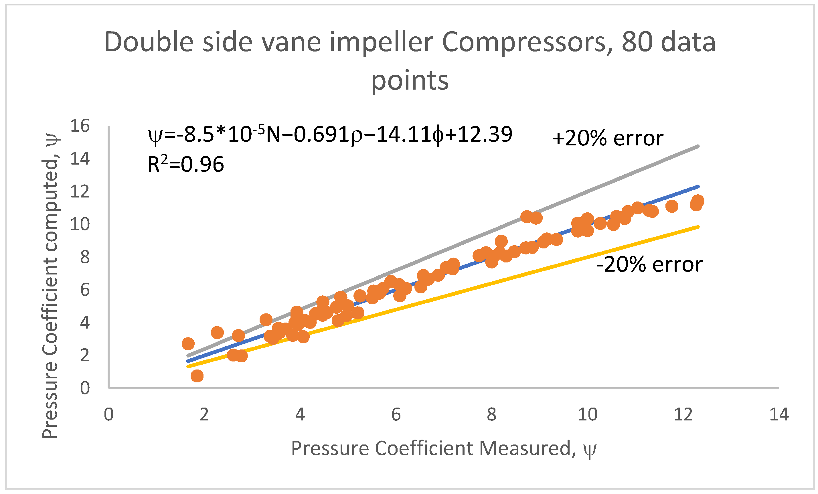
- ψ-ϕ correlation for compressors with double-side vane impeller
Since compressors handle compressible fluids, the correlation needs to include the density. In Equation (21), the data generated by Badami and Mura [14] used the initial density of the fluids.
The nature of this correlation is different from that given in Equation (7). Fitting the data in the form of Equation (4) resulted in poor estimates. Figure 6 shows the pressure coefficient as estimated using the correlation. It can be seen that the correlation predicts most of the data within an error of ±20%, while only 6% of the data fall outside the 20% error limit.
- ψ-ϕ correlation for pumps with double-side vane impeller
Compared to work on compressors, several more articles reported studies on regenerative flow pumps with diverse purposes. To cite a few, Badami [13] studied the influence of axial clearance, Nejadrajabali et al. [22] and Nejad et al. [24] studied the influence of vane angles, and Yoo et al. [34] studied the influence of impeller diameter. An exciting study by Nejadrajabali et al. [25] considered the influence of fluid viscosity. Most of the studies have reported the pressure coefficient against flow coefficient data, and these data were extracted to develop a correlation (Equation (19)) in the form of Equation (7), shown below.
The poor correlation coefficient of Equation (22) indicates the complexity of the phenomenon and the several variables that influence the performance. Hence, care should be exercised while using it. The estimated pressure coefficient using Equation (22) is shown in Figure 7. The error involved is more than 25% in several instances (approximately 30% of data are shown in the figure). In addition, the scatter is large at higher values of the pressure coefficient. A better correlation could be possible provided more variables, such as vane angles, vane surface roughness, axial and radial clearance, and side-channel geometry, were involved. However, such an approach would need a more complex equation and several inputs that could be discouraging to the practicing engineer.
- b.
- Hydraulic efficiency (η)–flow coefficient (ϕ) relation
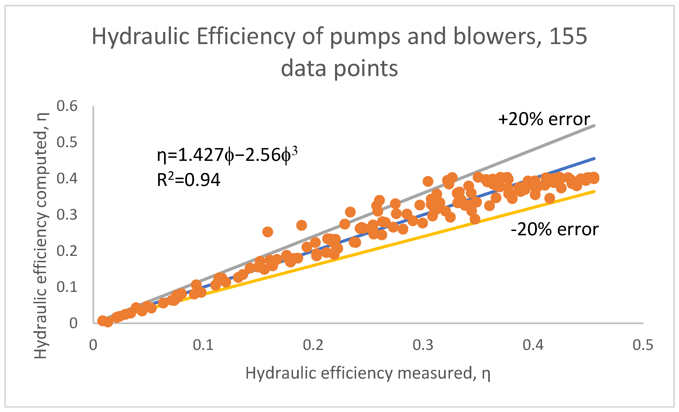
Like the treatment described for one-side vane impellers, choosing an appropriate flow coefficient based on the best efficiency is necessary. For double-side vane impellers, several researchers have also reported the variation in hydraulic efficiency with flow coefficient. The studies show that hydraulic efficiency is not sensitive to rotational speed, vane angles, and other geometric parameters. However, it was influenced by fluid viscosity, dropping in efficiency with a rise in viscosity [25]. The correlation (Equation (23)) relating hydraulic efficiency and flow coefficient has been obtained from 256 data points after excluding the data representing the effects of viscosity.
Figure 8 shows the parity plot of the measured (from literature) and computed (using correlation) hydraulic efficiencies of double-side vane impeller machines (pumps and compressors), and it can be seen that the correlation is successful in estimating the efficiency within an error of ± 20% for 90% of the data.
Equation (23) can be differentiated for the flow coefficient. When the derivative is equated to zero, the condition for maximum efficiency will result as φ = 0.51, and the maximum efficiency at this point will be 40%, which is similar to the result obtained for the one-side vane impeller machines.
- c.
- Axial clearance (G)
Badami and Mura [13] studied the influence of axial clearance on the performance of double-side vane impellers and found that a lower clearance produced higher pressures and hence higher pressure coefficients. However, unlike Badami and Mura [5], they maintained a constant speed of 8000 rpm. Hence, a correlation is derived for axial clearance based on the flow and pressure coefficients, unlike the three parameters in Equation (13). The correlation shown in Equation (24) is derived solely from the data of Badami and Mura [13].
- d.
- Stripper Angle (θs)
No parametric studies involving the stripper angle have been carried out for double-side vane impeller machines. For pumps, Badami and Mura [13] used 311°, Maity et al. [35] used 316°, and an angle of 344° was used by [23,24,25,26]. For hydrogen and air compressors, Badami and Mura [14] used an angle of 340°, whereas, for helium, they used 270°. A higher stripper angle results in more regenerations and, hence, a higher pressure. However, a minimum space needs to be provided to separate the inlet and outlet ports. Thus, it can be concluded from the literature that an angle of 315–345° can be safely used.
θs = 315° − 345°
- e.
- Mean side-channel radius (rs)
Badami and Mura [14] used a side-channel radius of 57 mm in a 138 mm dia impeller for hydrogen, whereas they used 117.6 mm for a 248 mm dia impeller for an air compressor. This works out to a side-channel radius over the impeller radius of 0.82 to 0.94. Hence, a typical value of 0.88 can be used. No studies reported the side-channel radius for pumps or blowers.
- f.
- Vane (blade) height (bh)
In the open literature, the vane height strongly correlates with the impeller diameter, where a higher vane height is needed for a larger diameter. The correlation for the vane height for pumps and compressors is given in Equation (27).
- g.
- Vane thickness (bt)
Vane thicknesses were not reported for double-side vane impeller machines. The thickness of the single-side vane machines was based on the rotational speed. Hence, the same reasoning can be applied to these machines, as well as the same equations.
- h.
- Number of vanes on each side (z)
Unlike the single-side vane impeller machines, the number of vanes in the present case is weakly dependent on the impeller diameter. The correlation between the number of vanes on each side and the impeller diameter has been derived and is shown in Equation (29).
It can be seen that the number of vanes obtained from Equation (29) will be close to 36 in most cases. This applies to both pumps and compressors.
- i.
- Side-channel groove radius (rsc)
Similar to the one-side vane impeller machines, the side-channel groove radius is a measure of the depth of the side-channel, except that, in the present case, the channel is present on either side of the impeller. Equation (18) can determine the side-channel groove radius.
- j.
- Number of vanes in the stripper region (Zst)
As shown in Equation (31), this parameter can be estimated similarly for the one-side vane impeller.
The number of vanes in the stripper region will be close to approximately 2–4, depending on the stripper angle. Karanth and Sharma [36] have used two vanes in the stripper region of their pump.
- k.
- Inlet and outlet vane angle (θi)
Most researchers used symmetric radial (90°) vanes. Nejadrajabali et al. [22] and Nejad et al. [24] have studied the influence of vane angles (40°–90°) and found that backward swept vanes (both at inlet and exit) with angles close to 80° yielded high efficiencies of 43%, and the pressure coefficient was also higher. Similar to the treatment of single-side vane impeller machines, a correlation between the vane angles, speed, flow, and pressure coefficients has been developed and is shown in Equation (32). As in the previous case, vane angles have been measured counter-clockwise.
3.3. Peripheral Vane Impeller Machines
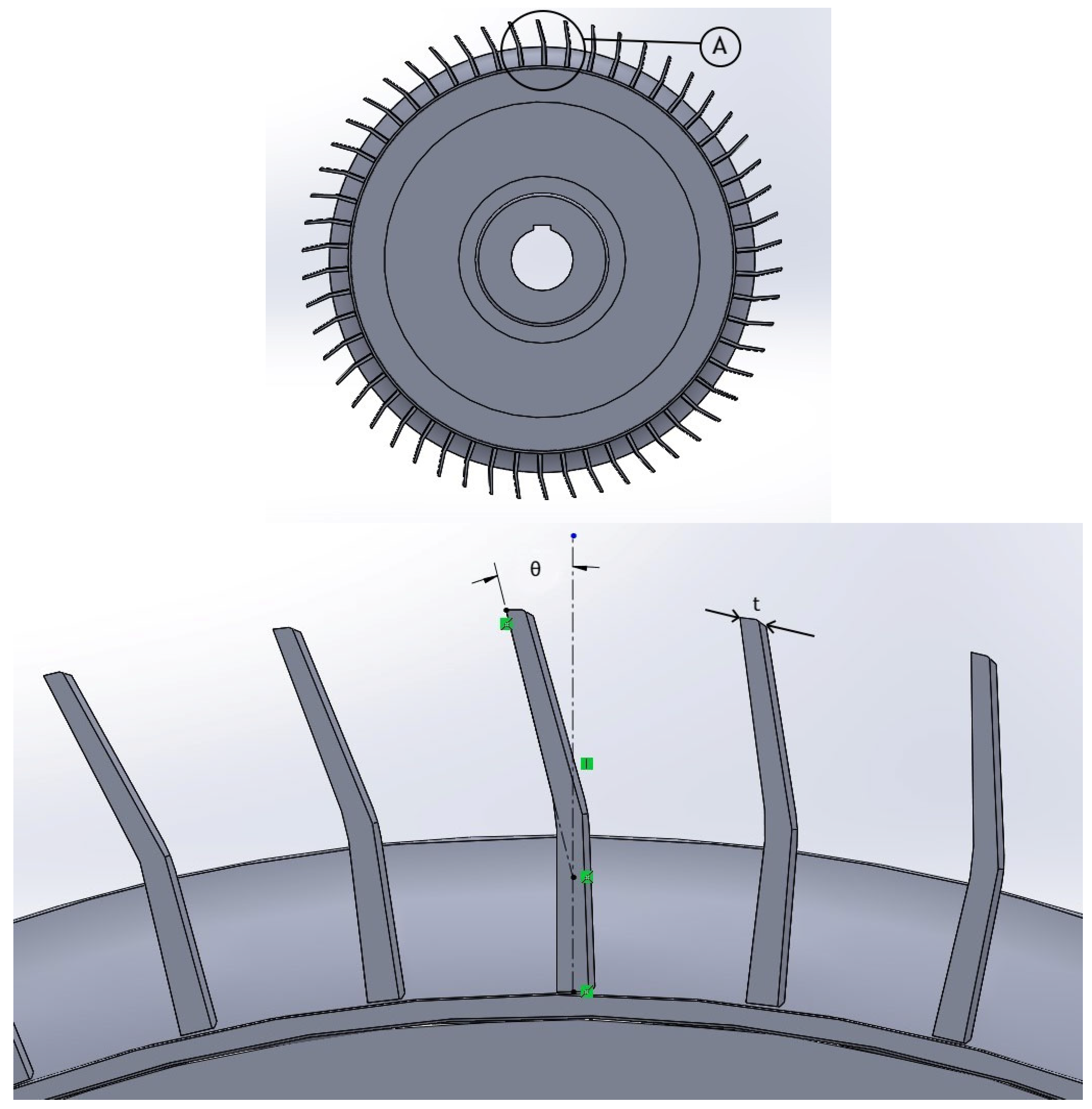
Peripheral vane impeller regenerative flow machines have been studied extensively [7]. Various inlet/outlet vane angles, vane shapes, and other geometric parameters have been studied. For the detailed schematic representation of design parameters, the reader is referred to Jang and Jeon [37]. Figure 9 below shows a peripheral vane impeller that has an inlet angle different from its exit angle. The exit angle and vane thickness are shown in the figure.
- a.
- ψ–ϕ correlation for peripheral vane impeller machines
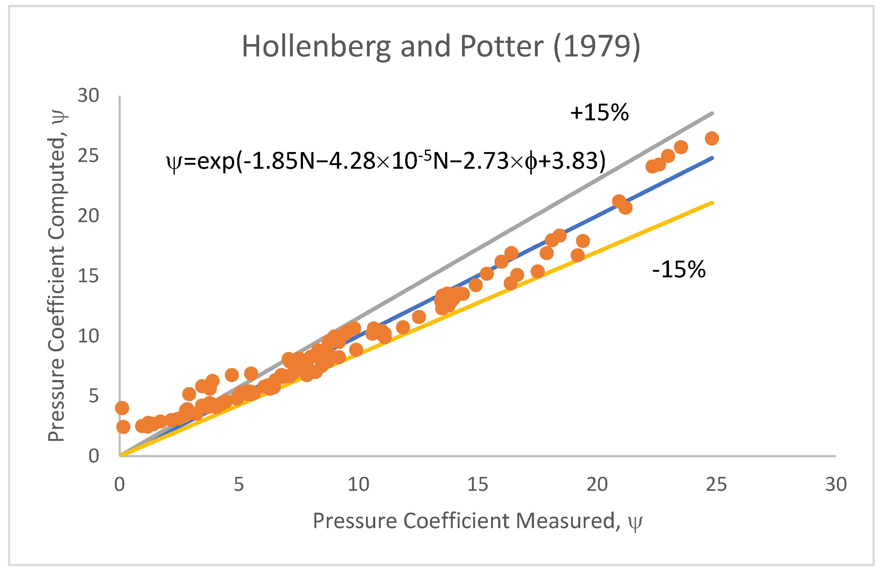
Regenerative flow blowers were studied by Lee et al. [2], Hollenberg and Potter [26], Jang and Jeon [37], and Mekhail [38]. Among these studies, Lee et al. [2] and Hollenberg and Potter [26] have studied the influence of rotational speed on performance. Further, the former varied the axial clearance between 0.25 and 0.75 mm and found a profound effect on the performance. Apart from this, most studies considered an axial clearance of around 0.2 mm. Hence, a correlation between the flow coefficient, pressure coefficient, and speed is derived using the data of Lee et al. [2] and Hollenberg and Potter [26] at an axial clearance of 0.2 and 0.25 mm, respectively, and is shown in Equation (33).
To show the effect of axial clearance, another correlation is derived using the data of Hollenberg and Potter [26], as shown in Equation (34).
The parity plot of Equation (34) is shown in Figure 10. It can be seen that the correlation can predict the measured pressure coefficient within a ±15% error for 85% of the data.
Regenerative flow compressors were studied by Raheel and Engeda [18], Raheel et al. [19], Raheel and Engeda [21], Brown [39], Cates [40], and Sixsmith and Altmann [41]. Among these, Sixsmith and Altmann alone considered the influence of speed. Moreover, they studied the influence of symmetric and asymmetric vanes on the performance and found that the former developed a higher pressure coefficient. The correlation in Equation (35) between the flow and pressure coefficient has been developed for symmetric vanes.
For asymmetric vanes, the correlation as given in Equation (36) is developed.
For regenerative flow pumps, the studies were carried out by Choi et al. [42], Jeon et al. [43], Quail et al. [12], and Zhang et al. [44]. Choi et al. [42] varied the vane angles and kept the speed constant at 1000 rpm, whereas Quail kept the speed constant and varied the flow rate. Zhang et al. [44] varied the blade inlet angle from 10–30° and found that the pressure coefficient is highest at 30°, even though the variation between different angles is approximately only 10%. The correlation was obtained for different speeds varying from 1000 to 4500 rpm.
The correlation coefficient obtained is poor, indicating that other operating parameters such as axial clearance and vane angles are substantially influential. However, as there are no adequate data to consider these variables, Equation (37) needs to be used with caution.
- b.
- Hydraulic efficiency (η)–flow coefficient (ϕ) relation
Several researchers have studied the relationship between hydraulic efficiency and flow coefficient. The general trend is that efficiency is a weak function of various geometric parameters. The correlation in Equation (35) is the same form as Equations (12) and (23). This Equation (38) contains the data of blowers, compressors, and pumps.
On differentiating Equation (38) to the flow coefficient, the condition for maximum efficiency would be at a flow coefficient of 0.644, and the maximum efficiency turns out to be 43%. Figure 11 shows the parity plot of the relationship between the measured and computed hydraulic efficiency using the correlation. It can be seen that most of the data fall within a ±20% limit, while approximately 18% of the data points are beyond a 20% error limit.
- c.
- Axial clearance (G)
Hollenberg and Potter [26] studied the influence of axial clearance on the performance of a blower at three values of 0.25, 0.5, and 0.75 mm and found that the pressure coefficient is maximum for the least amount of axial clearance. Like other machines, the axial clearance is very small and could be dictated by the manufacturing process and the cost of maintaining the precision. The correlation obtained for the data reported by Hollenberg and Potter [26] for blowers is given in Equation (39).
All other reported studies on compressors and pumps have used an axial clearance of 0.2 mm. As discussed for other machines, a low axial clearance delivered high pressures, but this comes at the cost of an expensive manufacturing process needed to maintain the low clearance. Based on the literature, a value between 0.2 and 0.75 is reasonable; the choice can be made depending on the budget.
- d.
- Stripper Angle (θs)
The stripper angle, also known as the side-channel wrap angle, is consistently maintained between 330 and 345° in the entire literature. As discussed earlier, a theoretical value of 360° is preferable to obtain the maximum number of regenerations. However, due to the finite sizes of inlet and outlet ports, the angle should be lower than 360°, but as close as possible. The range used to fix the stripper angle is given in Equation (40).
θs = 330° − 345°
- e.
- Mean side-channel radius (rs)
The side-channel radius ranged from 0.74 to 0.78 times the outer radius of the impeller. Hence, the relation in Equation (41) is proposed:
- f.
- Vane (blade) height (bh)
Details of the vane height have been provided by Choi et al. [42] for pumps and by Hollenberg and Potter [26] and Mekhail et al. [38] for blowers. Similar to the machines described earlier, the vane height is related to the outer impeller diameter, and the obtained correlation is given in Equation (42).
Even though no data are available for compressors regarding the vane height, Equation (42) can still be used, albeit cautiously.
- g.
- Vane thickness (bt):
Vane thickness values were reported by Choi et al. [42], Jang and Jeon [37], and Zhang et al. [44]. In these studies, the speeds were in the range of 1000–3300 rpm, which is on the lower end of the speed range seen in the literature. They chose a thickness of 2–3 mm. Since peripheral vanes are on the outermost region of the impeller, they need to be strong. The speed and fluid type determine their thickness and the temperatures encountered. No study reported the temperatures encountered in these machines. Hence, as a general rule, the vane thickness can be fixed using the correlation in Equation (43).
- h.
- Number of vanes (z):
The number of vanes is typically based on the impeller diameter. A simple relation between the number of vanes and the diameter is derived and given in Equation (44). This equation needs to be used as an initial estimate only.
The results obtained using this equation had a variation of ±2–10 vanes when verified with the reported data. This needs to be kept in mind while using this equation.
- i.
- Side-channel groove radius (rsc)
Similar to the earlier treatment given to this parameter, the side-channel groove radius can be estimated by the same Equation (30).
- j.
- Number of vanes in the stripper region (Zst)
No detailed data about the number of vanes in the stripper region are available. However, this parameter can be estimated analytically, as conducted earlier for other machines, using Equation (31).
- k.
- Inlet and outlet vane angle (θi)
Few researchers varied the vane angle to study the performance. Choi et al. [42] varied the angles from purely radial to forward and backward vanes in steps of 15°. They found that backward swept vanes inclined at 75° resulted in a maximum pressure coefficient of over 16. Mekhail et al. [38] varied the vane angle from purely radial to 45°. They found a maximum pressure ratio at an inclination of 55°. Zhang et al. [44] also studied the influence of vane angles and 80–60° and found the latter to be the most effective. Using these data, a correlation has been derived and is given in Equation (45). The angles are measured in a counter clockwise direction.
In Equations (20), (32), and (45), the value of vane angle θ can be obtained by taking the natural logarithm on either side of the equation.
- l.
- Choice of vane-type
While most studies reported radial vanes with either forward or backward swept angles, Choi et al. [42] considered the same with chevron vanes and performed a comparative experimental study on pumps. They concluded that the chevron vanes with an angle of 30° are best for pressure development and efficiency. Jeon et al. [43] carried out studies on a pump with an impeller having an S-shaped vane, and they found that its performance is better than the reference design, which was considered. Though an S-shaped vane appears to have better structural integrity, as it is a continuous element attached to the periphery of the impeller, its manufacture and fabrication could pose challenges. Considering these points, chevron vanes seem to be a better choice for pumps, while studies on blowers and compressors need to be carried out.
4. Conclusions
Several correlations have been derived to determine different types of regenerative flow machines. Experimental and computational data available in open literature have been used to arrive at the correlations. These correlations have been consolidated in Table 1, Table 2 and Table 3. No studies reported blowers with double-side vane impellers and compressors with single-side impellers. Wherever needed, suggestions for making an informed choice of parameters have been made. In addition, the design process of a blower with a single-side vane impeller is demonstrated in Appendix A to reproduce the data of Badami and Mura [1] for their 5000 rpm blower. The Table A1 in Appendix A also shows the actual design values used and the percentage of error. It can be found that the number of vanes, axial clearance, and vane height is computed at a relatively high error. The difference between the actual and computed values is only one vane for the number of vanes. The difference is only a fraction of a millimeter for the axial clearance. However, the actual and computed vane height is different by 7 mm, which is considerably large and needs to be addressed. As mentioned before, this work aims to present simple and working correlations for initial design purposes, and, hence, some errors are expected. The correlations presented in this work gave practically usable design parameters that would need some modification after computational and experimental investigations before arriving at the final design. Caution should be exercised while using the correlations, as they are applicable only for the range of operational parameters for which they were derived. For example, in the entire study, the range of the flow coefficient is 0–0.87. Major conclusions of this work can be summarized as follows:
- Simple correlations have been proposed for three different impellers and three different machines and their casings.
- The peripheral vane impeller machines are marginally better than others in hydraulic efficiency (~43%).
- The influence of density is negligible in pumps and blowers but is considerable in the case of compressors.
- The correlations proposed should be used only for a preliminary design. The final design and fabrication should be carried out based on the results of CFD simulations.
Author Contributions
S.M. and S.R. conceptualized the research. K.K. and F.M. developed the methodology. T.M.Y.K. compiled the correlations in the field of turbomachines. S.M. and F.M. extracted data from publications and developed the correlations. S.M. and N.S. prepared the manuscript. All authors have read and agreed to the published version of the manuscript.
Funding
This research received no external funding.
Informed Consent Statement
Not applicable to this research.
Conflicts of Interest
The authors declare no conflict of interest.
Nomenclature

| Symbol | Name | Unit |
|---|---|---|
| A | Area | m2 |
| D | Impeller diameter | m |
| G | Acceleration due to gravity | m/s2 |
| G | Axial clearance | mm |
| H | Head | m |
| N | Rotational speed (RPM) | s−1 |
| ΔP | Pressure rise | Pa |
| Q | Volumetric flow rate | m3/s |
| R2 | Correlation coefficient | - |
| RPM | Rotations per minute | min−1 |
| U | Blade tip velocity | m/s |
| Z | Number of vanes | - |
| Abbreviations | ||
| CFD | Computational fluid dynamics | |
| RFC | Regenerative flow compressor | - |
| RFM | Regenerative flow machine | - |
| RFP | Regenerative flow pump | - |
| Subscripts | ||
| C | Cross-sectional, clearance | |
| S | Stripper | |
| Sc | Side-channel | |
| St | Stripper region | |
| Greek Symbols | ||
| ψ | Pressure (or head) coefficient | - |
| ϕ | Flow coefficient | - |
| ρ | Density | kg/m3 |
| τ | Torque | N-m |
| ω | Angular velocity | radians/s |
| θ | Angle | Degree |
Appendix A
Table A1.
Design of a blower having single-side vane impeller (data of Badami and Mura [1], 5000 rpm blower).
Table A1.
Design of a blower having single-side vane impeller (data of Badami and Mura [1], 5000 rpm blower).
| S. No | Design Parameter | Formula | Calculated Value | Actual Value | % Error |
|---|---|---|---|---|---|
| 1 | Maximum efficiency | −9.1 | |||
| 2 | Flow coefficient at maximum efficiency | −4 | |||
| 3 | Pressure coefficient at maximum efficiency | Choosing N = 5000 rpm | 4.8 | 2.4 | |
| 4 | Impeller diameter | Choosing pressure ratio as 1.025, ΔP = 2500 Pa. | 138 mm | −5.34 | |
| 5 | Side-channel radius | 57 mm | −8.1 | ||
| 6 | Vane height | 24 | −27.9 | ||
| 7 | Vane thickness | Choose 6 mm | 8 |
| |
| 8 | Side-channel groove radius | 15 mm | 0.0 | ||
| 9 | Number of vanes | 41 | 14.6 | ||
| 10 | Vane inlet/exit angle for symmetric vanes | On taking logarithm on either side and solving for θ, θ = 84° | 90 | −6.7 | |
| 11 | Side-channel angle | θs = 340°–345° | Choosing θs = 340° | 340° |
|
| 12 | Number of vanes in stripper region | 4 vanes | −25 | ||
| 13 | Axial clearance | 0.3 mm | 23.3 |
References
- Badami, M.; Mura, M. Theoretical model with experimental validation of a regenerative blower for hydrogen recirculation in a PEM fuel cell system. Energy Convers. Manag. 2010, 51, 553–560. [Google Scholar] [CrossRef]
- Lee, C.; Kil, H.G.; Kim, K.Y. The Performance Analysis Method with New Pressure Loss and Leakage Flow Models of Regenerative Blower. Int. J. Fluid Mach. Syst. 2015, 8, 221–229. [Google Scholar] [CrossRef]
- Karlsen-Davies, N.D.; Aggidis, G.A. Regenerative liquid ring pumps review and advances on design and performance. Appl. Energy 2016, 164, 815–825. [Google Scholar] [CrossRef] [Green Version]
- Quail, F.J.; Stickland, M.; Baumgärtner, A. A One-Dimensional Numerical Model for the Momentum Exchange in Regenerative Pumps. J. Eng. Gas Turbines Power 2011, 133, 093001. [Google Scholar] [CrossRef] [Green Version]
- Badami, M.; Mura, M. Comparison between 3D and 1D simulations of a regenerative blower for fuel cell applications. Energy Convers. Manag. 2012, 55, 93–100. [Google Scholar] [CrossRef]
- Nejad, J.; Riasi, A.; Nourbakhsh, A. Parametric study and performance improvement of regenerative flow pump considering the modification in blade and casing geometry. Int. J. Numer. Methods Heat Fluid Flow 2017, 27, 1887–1906. [Google Scholar] [CrossRef]
- Sreekanth, M.; Sivakumar, R.; Sai Santosh Pavan Kumar, M.; Karunamurthy, K.; Shyam Kumar, M.B.; Harish, R. Regenerative flow pumps, blowers and compressors–A review. Proc. Inst. Mech. Eng. Part A J. Power Energy 2021, 235, 1992–2013. [Google Scholar] [CrossRef]
- Quail, F.; Stickland, M.; Scanlon, T. Rapid manufacturing technique used in the development of a regenerative pump impeller. Rapid Prototyp. J. 2010, 16, 337–344. [Google Scholar] [CrossRef] [Green Version]
- Quail, F.; Scanlon, T.; Stickland, M. Study of a regenerative pump using numerical and experimental techniques. In Proceedings of the 8th European Turbomachinery Conference, Graz, Austria, 23 March 2009. [Google Scholar]
- Quail, F.J.; Scanlon, T.; Strickland, M. Development of a regenerative pump impeller using rapid manufacturing techniques. Rapid Prototyp. J. 2010, 16, 337–344. [Google Scholar] [CrossRef] [Green Version]
- Quail, F.; Scanlon, T.; Stickland, M. Design optimisation of a regenerative pump using numerical and experimental techniques. Int. J. Numer. Methods Heat Fluid Flow 2011, 21, 95–111. [Google Scholar] [CrossRef] [Green Version]
- Quail, F.J.; Scanlon, T.; Baumgartner, A. Design study of a regenerative pump using one-dimensional and three-dimensional numerical techniques. Eur. J. Mech.—B/Fluids 2012, 31, 181–187. [Google Scholar] [CrossRef] [Green Version]
- Badami, M. Theoretical and Experimental Analysis of Traditional and New Periphery Pumps; SAE Technical Paper; SAE International: Warrendale, PA, USA, 1997. [Google Scholar]
- Badami, M.; Mura, M. Setup and validation of a regenerative compressor model applied to different devices. Energy Convers. Manag. 2011, 52, 2157–2164. [Google Scholar] [CrossRef]
- Badami, M.; Mura, M. Leakage effects on the performance characteristics of a regenerative blower for the hydrogen recirculation of a PEM fuel cell. Energy Convers. Manag. 2012, 55, 20–25. [Google Scholar] [CrossRef]
- Raheel, M. A Theoretical, Experimental and CFD Analysis of Regenerative Flow Compressors and Regenerative Flow Pumps for Micro Turbine and Automotive Fuel Applications. Ph.D. Thesis, Michigan State University, East Lansing, MI, USA, 2003. [Google Scholar]
- Song, J.W.; Engeda, A.; Chung, M.K. A modified theory for the flow mechanism in a regenerative flow pump. Proc. Inst. Mech. Eng. Part A J. Power Energy 2003, 217, 311–321. [Google Scholar] [CrossRef]
- Raheel, M.M.; Engeda, A. Systematic Design Approach for Radial Blade Regenerative Turbomachines. J. Propuls. Power 2005, 21, 884–892. [Google Scholar] [CrossRef]
- Raheel, M.; Engeda, A.; Hamrin, D.; Rouse, G. The performance characteristics of single-stage and multistage regenerative flow compressors for natural gas compression application. Proc. Inst. Mech. Eng. Part C J. Mech. Eng. Sci. 2003, 217, 1221–1239. [Google Scholar] [CrossRef]
- Engeda, A. Flow Analysis and Design Suggestions for Regenerative Flow Pumps; ASME Paper No. FEDSM2003-45681; ASME: New York, NY, USA, 2003. [Google Scholar]
- Raheel, M.; Engeda, A. Current status, design and performance trends for the regenerative flow compressors and pumps. In Proceedings of the ASME International Mechanical Engineering Congress and Exposition, New Orleans, LA, USA, 1 January 2002; Volume 36444, pp. 99–110. [Google Scholar]
- Nejadrajabali, J.; Riasi, A.; Nourbakhsh, S.A. Flow Pattern Analysis and Performance Improvement of Regenerative Flow Pump Using Blade Geometry Modification. Int. J. Rotating Mach. 2016, 2016, 8628467. [Google Scholar] [CrossRef]
- Nejadali, J. Calculation of flow in incompressible regenerative turbo-machines with bucket form blades based on the geometry of flow path. Int. J. Numer. Methods Heat Fluid Flow 2019, 29, 2606–2621. [Google Scholar] [CrossRef]
- Nejad, J.; Riasi, A.; Nourbakhsh, A. Efficiency improvement of regenerative pump using blade profile modification: Experimental study. Proc. Inst. Mech. Eng. Part E J. Process. Mech. Eng. 2019, 233, 448–455. [Google Scholar] [CrossRef]
- Nejadrajabali, J.; Riasi, A.; Nourbakhsh, S.A. Performance evaluation of a regenerative pump under fluid viscosity enhancement. Mechanics 2017, 23, 852–858. [Google Scholar] [CrossRef] [Green Version]
- Hollenberg, J.W.; Potter, J.H. An Investigation of Regenerative Blowers and Pumps. J. Eng. Ind. 1979, 101, 147–152. [Google Scholar] [CrossRef]
- Cimbala, J.M.; Yunus, A.C. Fluid Mechanics: Fundamentals and Applications (SI Units), 4th ed.; Tata McGraw Hill Education Private Limited: New York, NY, USA, 2019. [Google Scholar]
- Holman, J.P. Experimental Methods for Engineers, 7th ed.; McGraw Hill Series in Mechanical Engineering; McGraw Hill: New York, NY, USA, 2017. [Google Scholar]
- Dubey, M.; Prasad, B.V.S.S.S.; Nema, A. Turbomachinery, 1st ed.; McGraw Hill Education: Noida, India, 2019. [Google Scholar]
- Meakhail, T.; Park, S.O. An improved theory for regenerative pump performance. Proc. Inst. Mech. Eng. Part A J. Power Energy 2005, 219, 213–222. [Google Scholar] [CrossRef]
- Pei, J.; Zhang, F.; Appiah, D.; Hu, B.; Yuan, S.; Chen, K.; Asomani, S.N. Performance Prediction Based on Effects of Wrapping Angle of a Side Channel Pump. Energies 2019, 12, 139. [Google Scholar] [CrossRef] [Green Version]
- Yahya, S.M. Turbines Compressors and Fans; Tata McGraw-Hill Education: New York, NY, USA, 2010. [Google Scholar]
- Griffini, D.; Salvadori, S.; Carnevale, M.; Cappelletti, A.; Ottanelli, L.; Martelli, F. On the Development of an Efficient Regenerative Compressor. Energy Procedia 2015, 82, 252–257. [Google Scholar] [CrossRef] [Green Version]
- Yoo, I.S.; Park, M.R.; Chung, M.K. Improved momentum exchange theory for incompressible regenerative turbomachines. Proc. Inst. Mech. Eng. Part A J. Power Energy 2005, 219, 567–581. [Google Scholar] [CrossRef]
- Maity, A.; Chandrashekharan, V.; Afzal, M.W. Experimental and numerical investigation of regenerative centrifugal pump using CFD for performance enhancement. Int. J. Curr. Eng. Technol. 2015, 5, 2898–2903. [Google Scholar]
- Karanth, K.V.; Sharma, N.Y. CFD analysis of a regenerative pump for performance enhancement. In Proceedings of the 3rd World Conference on Applied Sciences, Engineering & Technology, Kathmandu, Nepal, 27–29 September 2014; pp. 3–8. [Google Scholar]
- Jang, C.-M.; Jeon, H.-J. Performance Enhancement of 20 kW Regenerative Blower Using Design Parameters. Int. J. Fluid Mach. Syst. 2014, 7, 86–93. [Google Scholar] [CrossRef]
- Mekhail, T.A.-M.; Dahab, O.M.; Sadik, M.F.; El-Gendi, M.M.; Abdel-Mohsen, H.S. Theoretical, Experimental and Numerical Investigations of the Effect of Inlet Blade Angle on the Performance of Regenerative Blowers. Open J. Fluid Dyn. 2015, 5, 224. [Google Scholar] [CrossRef] [Green Version]
- Brown, A. A comparison of regenerative and centrifugal compressors. In Proceedings of the International Compressor Engineering Conference, West Lafayette, IN, USA; 1972. [Google Scholar]
- Cates, P.S. Study of the Peripheral Compressor; Oak Ridge Gaseous Diffusion Plant: Oak Ridge, TN, USA, 1966.
- Sixsmith, H.; Altmann, H. A regenerative compressor. J. Eng. Ind. 1977, 99, 637–647. [Google Scholar] [CrossRef]
- Choi, W.C.; Yoo, I.S.; Park, M.R.; Chung, M.K. Experimental study on the effect of blade angle on regenerative pump performance. Proc. Inst. Mech. Eng. Part A J. Power Energy 2013, 227, 585–592. [Google Scholar] [CrossRef]
- Jeon, S.Y.; Yoon, J.Y.; Jang, C.M. Optimal design of a novel ‘S-shape impeller blade for a microbubble pump. Energies 2019, 12, 1793. [Google Scholar] [CrossRef] [Green Version]
- Zhhang, F.; Fleder, A.; Böhle, M.; Yuan, S. Effect of suction side blade profile on the performance of a side channel pump. Proc. Inst. Mech. Eng. Part A J. Power Energy 2016, 230, 586–597. [Google Scholar] [CrossRef]
Figure 1.
Image of a double-side vane impeller and some important dimensions.

Figure 2.
Computed vs. measured pressure coefficient for one-side vane impeller pumps.

Figure 3.
Computed vs. measured pressure coefficient for one-side vane impeller blowers.

Figure 4.
Computed vs. measured pressure coefficient for one-side vane impeller blowers and pumps.

Figure 5.
Hydraulic efficiency of one-side impeller machines as estimated by the correlation.

Figure 6.
Pressure coefficient of double-side vane impeller compressor as computed by the correlation obtained from the data of Badami and Mura [14].
Figure 6.
Pressure coefficient of double-side vane impeller compressor as computed by the correlation obtained from the data of Badami and Mura [14].

Figure 7.
Pressure coefficient of double-side vane impeller pump as computed by the correlation.

Figure 8.
Hydraulic efficiency of double-side vane impeller machines as estimated by the correlation.
Figure 8.
Hydraulic efficiency of double-side vane impeller machines as estimated by the correlation.

Figure 9.
Schematic diagram of a peripheral vane impeller showing exit vane angle and vane thickness at exit. Portion A is magnified for clarity.
Figure 9.
Schematic diagram of a peripheral vane impeller showing exit vane angle and vane thickness at exit. Portion A is magnified for clarity.

Figure 10.
Parity plot of the pressure coefficient of blowers as measured and computed by correlation.
Figure 10.
Parity plot of the pressure coefficient of blowers as measured and computed by correlation.

Figure 11.
Hydraulic efficiency of peripheral vane impeller machines as estimated by the correlation.
Figure 11.
Hydraulic efficiency of peripheral vane impeller machines as estimated by the correlation.

Table 1.
Consolidated Table of Correlations for Regenerative Flow Pump design.
| Pumps | |||
|---|---|---|---|
| Design Parameter | Single-Side Vane Impeller | Double-Side VANE Impeller | Peripheral Vane Impeller |
| ψ-ϕ relation | |||
| η-ϕ relation | |||
| Impeller diameter | |||
| Mean radius of side-channel | |||
| Vane height, mm | d in mm | d in mm | d in mm |
| Vane thickness | |||
| Side-channel groove radius | |||
| No. of vanes | d in mm | d in mm | |
| No. of vanes in stripper region | |||
| Vane inlet angle * | |||
| Vane outlet angle * | |||
| Side-channel angle, θs | θs = 340°–345° | θs =315°–345° | θs = 330°–345° |
| Axial clearance, mm * | 0.2–0.9 mm | 0.2–0.75 mm | |
Table 2.
Consolidated Table of Correlations for Regenerative Flow Blower design.
| Blowers | |||
|---|---|---|---|
| Design Parameter | Single-Side Vane Impeller | Double-Side Vane Impeller ** | Peripheral Vane Impeller |
| ψ-ϕ relation | - | ||
| η-φ relation | - | ||
| Impeller diameter | - | ||
| Mean radius of side-channel | - | ||
| Vane height, mm | d in mm | - | d in mm |
| Vane thickness | - | ||
| Side-channel groove radius | - | ||
| No. of vanes | - | d in mm | |
| No. of vanes in stripper region | - | ||
| Vane inlet angle * | - | ||
| Vane outlet angle * | - | ||
| Side-channel angle, θs | θs = 340°–345° | - | θs = 330°–345° |
| Axial clearance, mm * | - | ||
Table 3.
Consolidated Table of Correlations for Regenerative Flow Compressor design.
| Compressors | |||
|---|---|---|---|
| Design Parameter | Single-Side Vane Impeller *** | Double-Side Vane Impeller | Peripheral Vane Impeller |
| ψ-ϕ relation | - | ||
| η-φ relation | - | ||
| Impeller diameter | - | ||
| Mean radius of side-channel | - | ||
| Vane height, mm | - | d in mm | d in mm |
| Vane thickness | - | ||
| Side-channel groove radius | - | ||
| No. of vanes | - | d in mm | d in mm |
| No. of vanes in stripper region | - | ||
| Vane inlet angle * | - | ||
| Vane outlet angle * | - | ||
| Side-channel angle, θs | - | θs = 315°–345° | Θs = 330°–345° |
| Axial clearance, mm * | - | 0.01–0.9 mm | 0.2–0.75 mm |
Publisher’s Note: MDPI stays neutral with regard to jurisdictional claims in published maps and institutional affiliations. |
© 2022 by the authors. Licensee MDPI, Basel, Switzerland. This article is an open access article distributed under the terms and conditions of the Creative Commons Attribution (CC BY) license (https://creativecommons.org/licenses/by/4.0/).
Share and Cite
MDPI and ACS Style
M., F.; M., S.; K., K.; R., S.; Sinaga, N.; Khan, T.M.Y. Regression-Analysis-Based Empirical Correlations to Design Regenerative Flow Machines. Energies 2022, 15, 3861. https://0-doi-org.brum.beds.ac.uk/10.3390/en15113861
AMA Style
M. F, M. S, K. K, R. S, Sinaga N, Khan TMY. Regression-Analysis-Based Empirical Correlations to Design Regenerative Flow Machines. Energies. 2022; 15(11):3861. https://0-doi-org.brum.beds.ac.uk/10.3390/en15113861
Chicago/Turabian StyleM., Feroskhan, Sreekanth M., Karunamurthy K., Sivakumar R., Nazaruddin Sinaga, and T. M. Yunus Khan. 2022. "Regression-Analysis-Based Empirical Correlations to Design Regenerative Flow Machines" Energies 15, no. 11: 3861. https://0-doi-org.brum.beds.ac.uk/10.3390/en15113861
Note that from the first issue of 2016, this journal uses article numbers instead of page numbers. See further details here.