
System Integrity Protection Schemes: Naming Conventions and the Need for Standardization


RISE Research Institutes of Sweden, SE-50115 Borås, Sweden
*
Author to whom correspondence should be addressed.
Energies 2022, 15(11), 3920; https://0-doi-org.brum.beds.ac.uk/10.3390/en15113920
Submission received: 2 April 2022
/
Revised: 15 May 2022
/
Accepted: 23 May 2022
/
Published: 26 May 2022
(This article belongs to the Special Issue Advances in Control and Analysis of Power Systems)
Abstract
:The energy transition is placing increased strain on power systems and making it challenging for Transmission System Operators (TSOs) to securely operate power systems. System Integrity Protection Schemes (SIPSs) are one of the solutions to address these challenges. SIPSs are a type of over-arching power system control; their goals are to increase the secure utilization of power system assets and to limit the impact of large disturbances on the system. Due to societal developments, the interest in utilizing SIPSs is increasing internationally, highlighting the importance of the standardization of terms and definitions to support collaboration between internationally interconnected power systems. This paper addresses the issue of increasing SIPS literature and the efficient exchange of knowledge about SIPSs by providing a new, up-to-date literature review and proposal for the standardization of SIPS terminology. The need for standardized terminology is highlighted by gathering various terms used to describe SIPSs and proposing a standardization of definitions, terms, and SIPS operational execution steps. The goal of the proposed standardization is to provide clarity and to decrease the sources of misinterpretation in an international collaborative environment. The analyzed literature is further classified according to the SIPS features it addresses, and conclusions about well-established and interesting future research areas are drawn. For example, it has been observed that the most commonly considered SIPS action is load shedding, while more sophisticated actions, e.g., using HVDC (High Voltage Direct Current) and FACTS (Flexible AC Transmission System) installations, controlled together with var rescheduling, are more in the realm of future research that may provide additional benefits to TSOs.
1. Introduction
The role of a modern transmission system is to provide a safe, reliable, and economically feasible interface for the exchange of electrical energy between producers, prosumers, and consumers. To do so, Transmission System Operators (TSO) have to make sure that the system remains stable and secure for different operating scenarios in case of the occurrence of plausible disturbances affecting the system’s operation. In the literature and in industry practice, such conditions are widely known as the N-1 criteria.
With increasing shares of renewables, faster power system dynamics, and demand from electricity markets for higher transfer capacities, the ability to satisfy the N-1 criteria may be jeopardized. If the N-1 criteria are not satisfied, a prompt adequate and fast set of actions may be needed to preserve the stable operation of the system in the case of the occurrence of a critical contingency. A manual intervention by a system operator in the control room may not be fast enough in this case and, therefore, the solution lies in deploying an automatic set of remedial actions. These automatic schemes are commonly known in the literature as System Protection Schemes, Special Protection Schemes, Remedial Action Schemes or, as referenced in this paper, System Integrity Protection Schemes (SIPSs).
Over the years, SIPS solutions have gained substantial interest from both industrial [1,2,3,4,5,6,7,8,9,10,11,12,13,14,15,16,17,18,19] and academic fields [18,19,20,21,22,23,24,25,26,27,28,29,30,31,32,33,34,35,36,37,38,39,40,41,42,43,44,45,46,47,48]. A number of these documents propose SIPS solutions to support situations where the N-1 criteria cannot be satisfied, or to secure a system against extreme events not considered in N-1 contingency planning analyses. SIPSs as solutions have been motivated by the fact that they increase power systems’ resiliency and bring higher financial benefits by allowing higher trading capacities. Recognizing the benefits of SIPSs, different organizations have, over time, brought their own specific regulations on the use of SIPSs and their definitions [1,2,3,4,49,50,51]. SIPS literature has grown significantly over the last decades, creating two important challenges:
- The standardization of terms and definitions: providing a common platform for the exchange of knowledge and experience of SIPSs arising from different countries with different SIPS terminology and standards;
- Updated comprehensive literature reviews: analysis and classification based on up-to-date literature on SIPSs to identify which areas of SIPS research and application are becoming established and which areas with research gaps remain to be addressed in the future.
This paper contributes to addressing these two challenges by providing recommendations on the standardization of SIPS nomenclature, the standardization of SIPS phases and execution steps, and by providing an up-to-date literature review and SIPS classification.
To address the issue of standardization, this paper gathers and compares terminology and definitions of SIPSs from different countries and authorities, outlining their similarities and main differences. From this comparison, recommendations on updates of certain definitions are proposed with emphasis on the need for the international standardization of terminology. Furthermore, this paper proposes a platform for knowledge exchange by providing a common description for the planning and operational phases of SIPSs, including a description of the main steps and actions which these phases encompass. The common description of SIPSs is drawn primarily by comparing descriptions originating from IEEE [1] and ENTSO-E [2], and attempting to emphasize their similarities and minimize their differences.
To provide an up-to-date literature review, this paper analyses literature going back twenty years, with emphasis on the most recent publications. The analyzed literature is classified according to SIPS objectives and mitigative action types, as well as on the detection methods for triggering, and of decision-making architecture. Compared to [20,52], this paper uses the literature classification to underline well-established SIPS solutions and to identify suitable areas for future research. Furthermore, the literature classification in this paper tries to answer questions related to the most considered SIPS actions and how these actions are used to address SIPS objectives. To illustrate SIPS implementation, as part of the literature review, the paper presents Nordic examples in a dedicated section, highlights the main objectives, and provides statistics on SIPS operation and terminology. From the described terminology, the issue of standardization is once more made apparent.
The paper is organized into seven sections:
- Introduction;
- Definitions and Terminology;
- Phases and Execution Steps;
- Literature Survey and Classification;
- Implementations in the Nordic Power System;
- Discussion;
- Conclusions.
2. Definitions and Terminology
The variety of terms and definitions used for solutions related to SIPS makes it difficult to address such solutions from an international perspective. Therefore, in this section, we have gathered some of the definitions used today with the intention to outline the similarities and main differences and to provide recommendations on a common definition. Furthermore, the usage of terms with different meanings constitutes a risk for misunderstanding. A list of preferred terms is therefore presented, together with the descriptions of a variety of terms used to express the functionalities and structures of SIPSs.
Throughout this report, we use the expression SIPS (System Integrity Protection Scheme), as proposed by [5], referring to control schemes of a similar type, such as Special Protection Schemes, System Protection Schemes, and Remedial Action Schemes. The expressions Special Protection Schemes and System Protection Schemes come with two disadvantages: firstly, their use is mixed and has changed historically [4]; secondly, the acronym SPS may refer to both expressions. RAS is another commonly used expression which is inhibited by a stringent definition [49]. Integrity is a term seen as a central part of control scheme functionality [1,6,51], intending to preserve the interconnected operation of power systems from a broad perspective. Furthermore, with SIPS being an acronym less prone to create confusion, we believe that the expression of System Integrity Protection Scheme is the most appropriate to use.
2.1. SIPS Definitions
The role of SIPSs has been defined by different entities across the world. Some of the commonly used definitions are provided by: the European Network of Transmission System Operators for Electricity (ENTSO-E), the North American Electric Reliability Corporation (NERC), and the Institute of Electrical and Electronics Engineers (IEEE).
In [1], IEEE describes SIPSs as enhancing security and preventing the propagation of disturbances for severe system emergencies. SIPSs are used to stabilize power systems by taking mitigative control actions. Both the IEEE and CIGRE [51] consider SIPSs to encompass Special Protection Systems and RAS, as well as underfrequency and undervoltage load shedding (UFLS, UVLS) and out-of-step (OOS) protection schemes.
In [2], ENTSO-E distinguishes between System Protection Schemes (SyPSs) and Special Protection Schemes (SpPSs). SyPS are designed to stabilize the power system when a widespread collapse is imminent. SpPSs are designed to provide acceptable system performance in systems or scenarios where there is a lack of N-1 redundancy. SyPSs are generally response-based, while SpPSs are mainly event-based.
In [49], NERC prefers the term RAS, considering schemes with objectives including maintaining the stability of the bulk power system and limiting the impact of cascading or extreme events. RAS are designed to take corrective actions, including, e.g., generation adjustment or tripping, load tripping, or system reconfiguration. Several items are listed as not individually constituting a RAS, including UFLS, UVLS, and OOS. The main reason for this exclusion is that they are considered protective functions, and not explicit schemes themselves, and therefore are covered by other standards, [7].
There are several details differentiating the views of the SIPSs presented above. However, common factors relate to the support of stability and security, and to mitigating the extent of large disturbances. Our proposal is to highlight the three parts of the SIPS definition related to the goals, the objectives, and the means of SIPSs:
- A SIPS is defined by its goals, objectives, and means, which are:
- Goals: Increase the power system reliability and/or capacity;
- Objectives: Prevent the degradation of the power system technical performance in cases where the pre-contingency state of the system is nonsecure or in cases of extreme contingencies, regarding stability and/or overloading phenomena;
- Means: The objectives are met through the use of selected mitigative actions which are automatic, predetermined, and coordinated.
Thus, this proposed definition can be used to describe SIPSs in general, and to clearly distinguish specific implemented SIPS solutions. This implies a limited need for additional definitions; instead, the definition can support the classification of sub-categories of SIPSs with the same basic definition, further clarifying naming conventions.
2.2. SIPS Terminology
SIPSs encompass a comprehensive set of concepts and solutions, ranging from widely implemented schemes to complex site-specific solutions. There are, however, several important actions which are part of the design of any SIPS solution, namely: arming, triggering, and mitigation. Due to the inconsistency in nomenclature, standardization would also be preferable here. The proposed terms, as presented in Table 1, are suggestions to decrease the risk of misunderstanding. The significance of this risk is highlighted by terms used in the literature, which are partly included in the table under the heading “other terms”.
3. Phases and Execution Steps
As discussed in the previous section, countries and their authorities quite often have different definitions of System Protection Schemes, Special Protection Schemes, Remedial Actions, and System Integrity Protection Schemes. They all describe a set of actions executed in a specific order and manner to preserve a power system in its operational constraints when subjected to foreseen or unforeseen disturbances. While the actions themselves are quite similar, the main differences in the definitions are related to the terms that are used to describe these actions and the steps in their execution. For example, some TSOs may refer to the term activating SIPSs as deploying mitigative actions. Others may use activating to mean the arming of SIPSs. Furthermore, a comparison of solutions from the literature may often lead to ambiguities as to when certain functions are executed, e.g., at which phase the extent of SIPS mitigative actions is decided. To compare different solutions of SIPSs, besides using the same terminology, it is important to also use the same or at least similar frameworks to classify SIPS execution steps and the actions contained in these execution steps. This section intends to provide a common framework by comparing some of the already proposed frameworks, highlighting their similarities, and bridging their differences.
The process of SIPS deployment can, in general, be divided into two phases: the planning phase and the operational phase. The literature is mostly consistent when stating that the planning phase consists of the initial calculations for mitigative action extent and their arming and triggering criteria. More pronounced differences exist in describing the structure of the operational phase and its main steps. To illustrate the differences and similarities, the operational phases, as described by IEEE [1] and ENTSO-E [2], are compared.
The IEEE/PES Power System Relaying Committee [1] defines three main steps in the SIPS operational phase:
- 1.
- Monitoring and Detection:
- The monitoring of the system states and deciding if there is a need to arm a particular SIPS;
- 2.
- SIPS Logic Processing:
- Arming calculations including decisions on the extent of mitigation actions;
- 3.
- Mitigation:
- The monitoring of system states and, in case thresholds are exceeded, the triggering of mitigation actions.
The ENTSO-E [2] does not explicitly distinguish between the three steps as IEEE does. However, [2] does mention the logic that is supposed to detect if the system is in a normal, alert, or emergency state. This logic could be equivalenced with the Monitoring and Detection step as proposed by IEEE. Furthermore, depending if the system transitions from normal to an alert or emergency state, a set of Special Protection Schemes or System Protection Schemes are armed, respectively, as proposed by ENTSO-E. Special Protection Schemes and System Protection Schemes together form a Defense Plan which might be the term ENTSO-E [2] uses as an equivalent to SIPSs as used by IEEE [1]. Therefore, the ENTSO-E step to decide which Special Protection Schemes or System Protection Schemes should be armed corresponds to the IEEE second step of SIPS execution: SIPS Logic Processing. Ultimately, both the IEEE and ENTSO-E envision a step for the deployment of SIPS mitigative actions named the Activation Step by the ENTSO-E and the Mitigation Step by the IEEE.
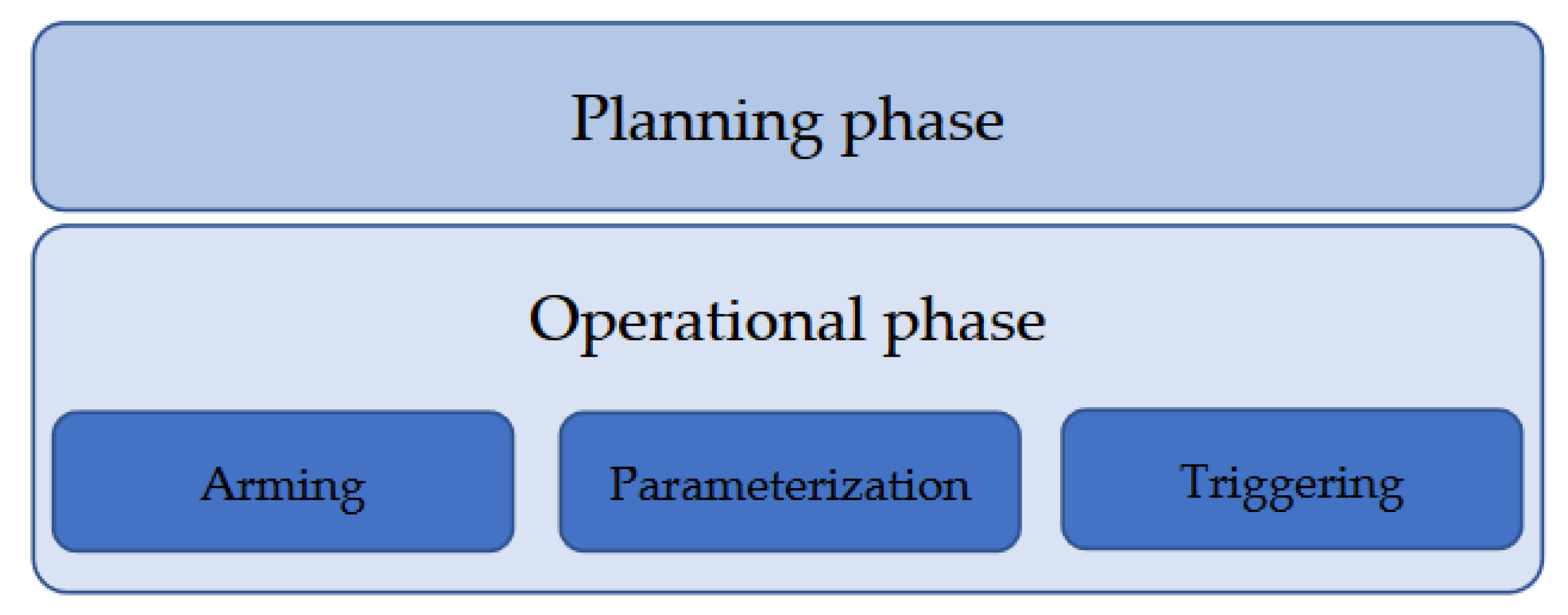
To avoid discrepancy between the definitions of the main steps of SIPS execution, and to provide a platform for comparison and knowledge exchange between the SIPS solutions described by either IEEE [1] or ENTSO-E [2] definitions, this paper proposes and motivates the use of the SIPS planning and operational phases illustrated in Figure 1. The execution steps of the operational phase present a consistent logic of describing the intended outcome of the actions encompassed by each step. First is the Arming step, which corresponds to the IEEE Monitoring and Detection step and the corresponding definitions of ENTSO-E. Instead of naming the step after its input as proposed by IEEE, we name it after its expected outcome which is the decision to arm or not to arm the SIPS. The second step encompasses actions which decide on the extent of the mitigative actions and their triggering mechanisms. The definition of this step is maybe the most problematic, as the aforementioned actions vary significantly from country to country. Here, the obvious advantage of naming the step according to its intendent outcome is obvious. In this case, the step outcome is the parameterizing of the SIPS for a specific operating state of the system. Therefore, this is named the SIPS Parameterization step. The final execution step in Figure 1 includes actions which monitor system states of interest, predetermined in the previous Parameterization step, and triggers the mitigative actions if these states reach the predetermined criteria. Thus, named after its outcome, this is called the Triggering step and corresponds to what the IEEE defines as the Mitigation step or the ENTSO-E defines as the Activation step.
The choice of the execution steps shown in Figure 1 and their naming has been established based on the following principles:
- Consistency: All execution steps are named after the outcome of the set of actions they represent. For example, the Arming step represents a set of actions that lead to SIPS being armed or not. Similarly, the Triggering step describes a set of actions that lead to the triggering of SIPS mitigative actions or not;
- Uniqueness: Each step name uniquely defines the set of actions that it represents. For example, the Parameterization step is describing actions used to set the SIPS triggering criteria and the mitigative action extent. On the other hand, the name “Parameterization” is hard to confuse with the first or third step in the operational phase as the first and the third steps do not include any actions that set the parameters of SIPSs. In case of IEEE naming, the first step named Monitoring and Detection can be confused with the third step, as both steps include actions related to monitoring and detection.
- Generality: The name of each execution step should be general enough not to exclude any action comprised in the particular step.
The following subsections go into more detail of each of the execution steps from Figure 1.
3.1. Arming
By the earlier mentioned definitions, SIPSs are supposed to mitigate the effects of certain contingencies that can lead to power system instability and consequent possible widespread blackouts. The actions from the Arming step are supposed to detect the state of the system in which a contingency event may jeopardize a stable system operation. ENTSO-E [2] classifies these states as alert and emergency states, with respect to the increasing severity of the possible contingency event. To identify the need for SIPS arming, the actions in the Arming step continuously monitor and evaluate the system against one or several of the following phenomena, in accordance with the SIPS objective:
- Voltage instability;
- Small signal angle instability;
- Transient angle instability;
- Frequency instability;
- Components’ thermal overloading,
If it is detected that the system has an operational state where there is an increased risk that a contingency might lead to any of the listed phenomena, the SIPS is armed. This is often completed by comparing the operational state to a pre-defined arming criteria identified in the planning phase.
3.2. Parameterization
After the need for the arming of the SIPS has been identified in the Arming step, a choice must be made on which mitigative actions should be used and how those should be triggered. In other words, SIPS parameters should be configured to efficiently and reliably address a non-secure or—as the ENTSO-E [2] defines it—alert/emergency state of the system.
SIPS parameters, as defined by this paper, may be of a discrete or continuous nature. An example of discrete SIPS parameters is the choice of particular SIPS actions, or the choice of signals monitored for making a decision on the triggering of the actions, etc. Continuous SIPS parameters would be threshold levels for triggering mitigative actions, the extent of the mitigative actions, etc. Some or all of these parameter values may have already been determined during the SIPS planning phase. However, the assumptions used in planning may not correspond to the conditions in operation. In this case, to preserve SIPS efficiency and reliability, SIPSs might benefit from parameterization in the operational phase. As proposed by this paper, the set of actions used to parameterize SIPSs in the operational phase is named the Parameterization step.
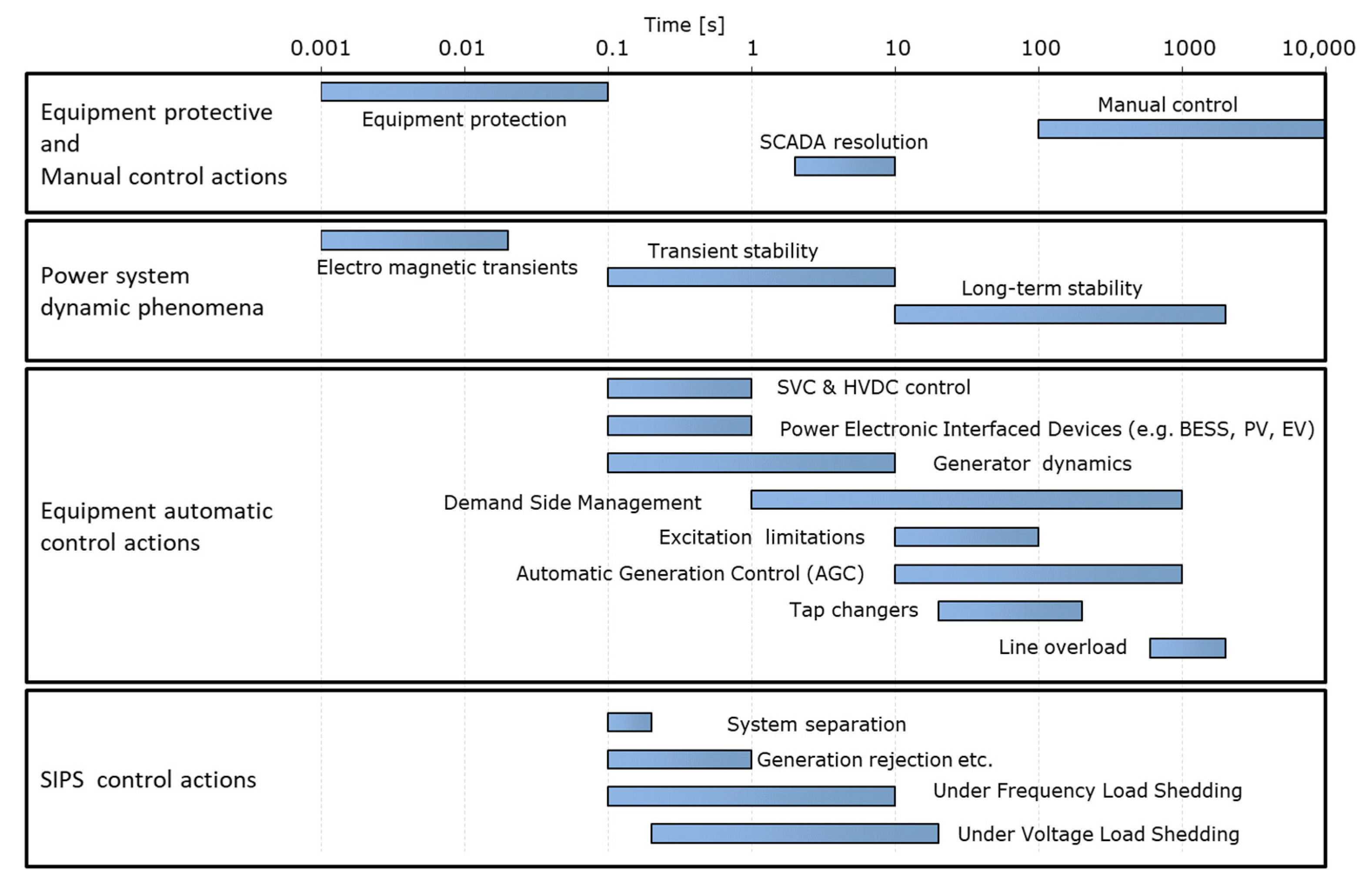
To configure the parameters of SIPSs in the operational phase, information including the current operating point of the system, system configuration, availability and the cost of resources for mitigation, as well as possible contingencies that may steer the system towards instability phenomena and subsequent black-out, may be needed. Furthermore, depending on the SIPS objective, required mitigative actions have to be deployed within a specific timeframe, as indicated in Figure 2. As an initial point for determining SIPS parameters, the parameter values calculated in the SIPS planning phase can be used.
Based on how the information for setting SIPS parameters is collected, and how mitigative actions are to be deployed, SIPSs can be parameterized in the following manners:
- Decentralized:
- ○
- Local: SIPS parameterization is performed locally, including the measuring of system states needed for making a decision on the value of SIPS parameters;
- ○
- Distributed: System states are measured locally; however, the SIPS is parameterized by exchanging information between neighboring local devices, e.g., Intelligent Electronic Devices (IEDs), that participate in the SIPS parameterization;
- Centralized:
- Measurements are collected centrally, and a centralized decision is made on the SIPS parameter settings. It should be noted that the triggering of a SIPS is usually not performed by the centralized system but by the local devices, e.g., IEDs, which are instructed by the centralized system on when and how to trigger mitigative actions. The main reason for this is to increase the speed of deploying mitigative actions.
After the Parameterization step, armed SIPSs are ready to detect and appropriately respond to critical system contingencies by the triggering of chosen mitigative actions.
3.3. Triggering
The Triggering step of SIPS execution from Figure 1 includes a set of actions for the monitoring and detection of critical system contingencies and their mitigation. A contingency (or a set of contingencies) that results in an undesirable system state, requiring the triggering of mitigative action or the actions of the SIPS can, according to [2,22,23,24], be detected by two different types of methods:
- Event-based: The system registers discrete signals indicating the status change of certain components, e.g., the opening of a circuit breaker or the activation of a protective relay, and makes a decision based on these to trigger dedicated SIPS mitigative actions;
- Response-based: The system observes the continuous dynamic system response, e.g., voltage measurements, and based on it determines if there is a need to trigger the SIPSs’ mitigative actions.
Other instances in the literature [9,25,26] propose three types of detection methods: event-based, parameter-based, and response-based. While the here-mentioned event-based methods correspond to the above-defined one, parameter-based and response-based methods, as defined by [9,25,26], can be regarded as subsets of the above-defined response-based method by [2,22,23,24]. To avoid confusion in the naming and classification between the methods from [2,22,23,24] and [9,25,26], we propose the following classification of the detection methods for triggering:
- Event-based: defined as above;
- Response-based: defined as above;
- (a)
- Limit-based: Monitoring the dynamic system response, e.g., voltage measurements, and if the monitored quantity reaches the limit (threshold set in Parameterization step), predetermined SIPS mitigative actions are triggered. These methods correspond to the parameter-based methods as defined in [9,25,26];
- (b)
Upon the occurrence of a contingency in the system, timely SIPS reaction is of essence to prevent potentially serious consequences. Therefore, detection methods identifying the need for the triggering of mitigative actions, in addition to needing to be reliable, also have to be fast enough. For that purpose, event-based and limit-based methods usually use look-up tables [27]. When it comes to trajectory-based methods, the use of look-up tables may not be feasible due to the complexity of making decisions on triggering and the extent of the mitigative actions. Instead, some literature examples propose the use of machine learning and data-mining approaches [26,28,29,30]. For example, machine learning methods can be used to classify post-contingency system responses into the ones requiring and not requiring the deployment of mitigative actions. Furthermore, classification can be expanded such that certain system responses trigger specific sets of mitigative actions. Compared to mathematical methods, machine learning methods can generally be faster in identifying a need for the triggering of mitigative actions, as they do not require carrying out computationally demanding tasks in real time.
While being a very powerful tool, machine learning methods also have their limitations. The training of machine learning models requires representative data of the possible scenarios that the system may encounter. Therefore, the performance of machine learning models can be directly correlated with the quality of the training data [32,33,34]. While the quality of the data may be enhanced with pre-processing, issues such as over-fitting, misrepresentation, or the non-equal representation of scenarios may appear [32,33,34]. For example, if there exists a scenario (e.g., different operating points or different contingency combinations) that is not well represented in the training data, there is a risk that the detection method would fail to correctly trigger the SIPS in the case of the occurrence of such a scenario. On the other hand, mathematical methods do not depend so much on historical data but instead use more physics-driven models for the analysis of the system’s phenomena making them more reliable and trustworthy, as seen by system operators so far.
4. Literature Survey and Classification
After defining SIPSs and describing their main execution steps in the previous two sections, this section tries to provide information on the most common SIPS types, i.e., which are the most common combinations of their features as analyzed/described in the literature. For this purpose, a literature review has been carried out. Most of the analyzed references come from academia with some also describing industry practice. The references have been classified according to the type of SIPS features that they are addressing. The classifications are provided in Table 2 and Table 3.
One purpose of reference classification is to identify if certain SIPS types are more common in the literature than others. Some of the questions that the classifications presented in Table 2 and Table 3 try to answer are the following:
- What are the most considered SIPS mitigating actions in the literature?
Based on Table 2, the most considered mitigating action in the literature is load shedding, followed by generation rejection and generation rescheduling. These type of actions are historically the most used in practice, so it is no surprise that they are well represented in the literature. However, recent references propose less expensive—but not so practice-proven—mitigating actions involving the use of power electronics to, e.g., provide a more flexible mitigation strategy, and intelligent controlled network splitting and reconfiguration. The latter methods, while not so proven in practice, show considerable potential for the future development of more advanced SIPSs. Looking further at Table 2, it can be seen that the mitigative actions that target the adjustment of active power flows in the grids are much more considered than the methods where reactive power is used. It is not certain why this is the case. However, one reason might be that the objectives of SIPSs are more easily satisfied by altering active power flows than reactive power flows. A follow-up question that needs to be answered is: what are the costs of methods that alter active power versus methods that alter reactive power flows in the grid?
- What are the most considered mitigating actions in the literature for certain SIPS objectives?
Among the analyzed references, the most pronounced correlation is between voltage stability objective and load shedding as a mitigation to improve it. It is also worth noting that controlled islanding and FACTs control as mitigation were considered in the analyzed literature only for improving the transient angle stability objective.
- What are the most considered detection methods for SIPS triggering events in the literature?
From Table 3, it seems that the analyzed literature targets equally event-based and response-based detection methods for triggering. Among response-based methods, trajectory triggering is more represented. This means that the literature opts for more advanced detection methods (trajectory triggering) when the measurement of the system response is available. This is somewhat reasonable, as trajectory-triggering detection methods allow the extent of mitigative actions to be scaled more precisely, making them less expensive and possibly more reliable than limit triggering. On the other hand, when it comes to reliability and simplicity, practice tends to favor event-based detection methods. This may be one of the reasons why they are equally well represented in the literature as more advanced, but also more complex, response-based methods.
5. Implementations in the Nordic Power System
The purpose of this section is to share information from the real-life implementation of SIPSs. The Nordic interconnected power system is managed by the TSOs of the four Nordic countries: Denmark, Finland, Norway and Sweden. As mentioned in the section on definitions and terms, the fact that there is no general nomenclature used for terms and definitions related to SIPSs might cause confusion. This is also the case for Nordic terminology.
In [53], Nordic TSOs describe that System Protection Schemes are used to preserve system integrity and provide acceptable system performance. Furthermore, in [50], System Protections are described to limit the impact of faults and to securely increase the capacity of the transmission network.
On a national level, the nomenclature differs: the TSO in Norway (Statnett) uses System Protection (Norwegian: Systemvern [54]) as a general term for SIPSs, while the TSO in Sweden (Svenska kraftnät) considers Network Protection (Swedish: Nätvärn [3]) as the main term. Svenska kraftnät considers System Protection (Swedish: Systemvärn [3]) as one type of Network Protection, and as a voltage or frequency controlled and used to counteract system collapse, i.e., similar to the ENTSO-E definition of System Protection Schemes. Additionally, the terminology used for arming and triggering can easily become confusing: the Swedish TSO uses the terms in operation for arming and activate for triggering (Swedish: i drift/aktivera [3]), while the Norwegian TSO uses activate for arming and trigger for triggering (Norwegian: aktivering/utløse [54]).
The collaboration between the Nordic TSOs includes detailed agreements regarding SIPSs, as described in the Nordic System Operation Agreement [15]. Table 4 presents a mapping of SIPSs in the Nordic power system. As illustrated in the table, SIPS are implemented with several design objectives utilizing various mitigating action types and detection methods.
SIPSs with the goal to increase both system reliability and capacity are utilized in the Nordic system. The latter type is subject to several requirements which may, depending on the consequence of a SIPS malfunction, include the redundancy and reliability levels of the SIPS’s functionality as well as a mutual agreement between all Nordic TSOs if a SIPS function might result in an event larger than the dimensioning fault [55].
In [15], several SIPSs are mentioned to support stability without defining which stability phenomena they relate to. Therefore, an objective called “Stability undefined” is included in the table. Regarding SIPSs with the objective to support frequency stability, mitigating actions are adapted to the combined operational reserves where the trigger levels for response-based SIPSs are set to act in case the frequency continues to drop or rise even after the frequency-controlled disturbance reserves have been used [15]. HVDC control (emergency power) is a mitigating action available for all DC installations in Nordic power systems and other AC systems [15]. The HVDC control is used in situations where the frequency is above or below a pre-defined limit and the link is not already providing its maximum possible contribution. Additionally, load shedding, generation start-up and grid reconfiguration are used by response-based (limit-based) SIPSs for monitoring frequency deviation. Grid reconfiguration is a remedial action type not explicitly identified in the literature survey which, in Nordic systems, is a commonly used action type for SIPSs with objectives related to both stability and overloading.
Event-based SIPSs are often complex and involve mitigating actions for controlling facilities far from the relays which trigger the SIPSs. These SIPSs are not always armed: it rather depends on the operational situation.
SIPSs are deployed to various degrees, with national strategies largely influencing the level of SIPS deployment. In the Nordic power system, the Norwegian TSO Statnett employs SIPSs to a large extent to enable transfer capacities above the conventional N-1 levels [54], while the Swedish TSO Svenska kraftnät uses SIPSs to a lesser extent. There are, however, ongoing activities to further use SIPSs to increase the capacities of limited bottlenecks in Sweden [56]. In the Norwegian power system, SIPS implementation has been progressing since the 1980s, and the intensified SIPS penetration implies an augmented operational demand in terms of both utilization and the complexity of the power system [21].
The extensive use of SIPSs may originate from the fact that the Norwegian TSO, Statnett, considers the use SIPSs as a social, economic, rational solution to mitigate local constraints or operational restrictions [54]. In the Norwegian regulations describing the practices related to SIPSs, it is, however, underlined that the system operator must balance the risk and cost related to a potential triggering of a SIPS to the cost of other system controls (like the operators themselves limiting the power flow on certain lines so the system will manage a lost line even without SIPS remedial action) [54]. The risk evaluation considers different conditions, such as the weather. In an extreme weather situation, with a higher risk of triggering a SIPS, the operator might find it more reasonable to control the power flow than to arm a SIPS. The regulation also states that the system operator should consider that armed SIPSs increase the system complexity and might introduce an imbalance into the system. The manual arming of SIPSs is based on analyses from the planning phase applied in the operational phase, depending on the actual operational situation. Similarly, the extent of mitigating actions is updated in the operational phase based on state estimator data [12].
In the Chilean power system, SIPSs are utilized in a similar manner as in the Norwegian case: to increase the capacity of the transmission grid. This is well described in [11], where four economical drivers are presented for Chilean SIPSs: releasing congestion for an economical dispatch; time shifting between generation and transmission; maximizing the availability of generation assets; and avoiding rationing risk by relieving congestion.
The operational cost of SIPSs in Norway is presented in Statnett’s annual report [57], and includes the cost for the triggering of generation rejection (or rescheduling) and load shedding. Production units connected to a SIPSs receive a yearly fee and, on top of this, they also receive pre-defined compensation in case the unit is triggered. In case of load shedding, the TSO compensates according to the penalty fees which the network owners have for non-delivered energy. The yearly cost is thus dependent on the number of times these types of SIPSs are triggered, and on the amount of load or production which is affected (the mitigative action extent).
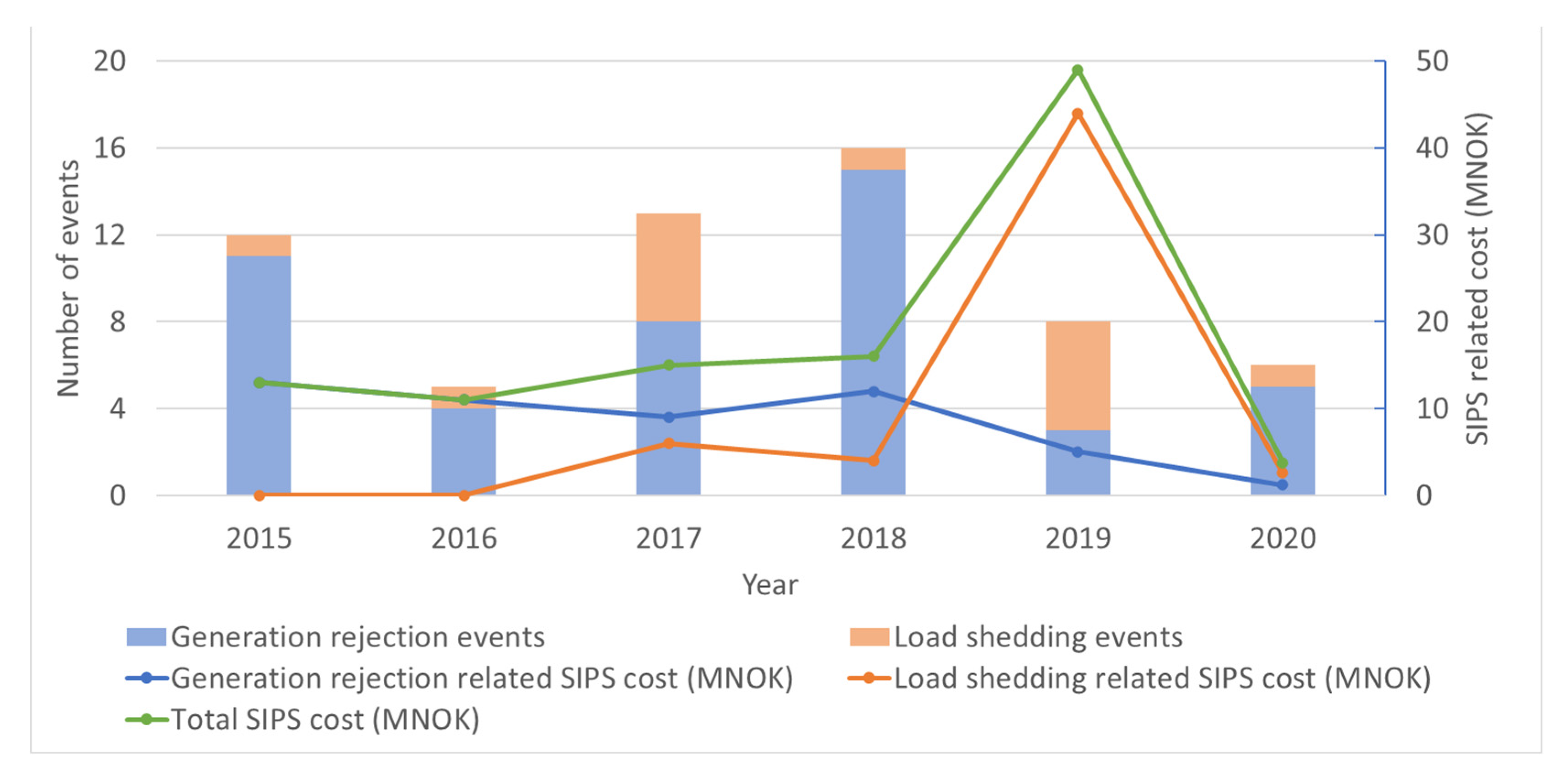
Figure 3 presents the number of load shedding and generation rejection events and the corresponding cost for the years 2015 to 2020 [58]. There is a clear peak in 2019 which relates to load shedding, which was triggered on five occasions resulting in a load shedding amount of about 1730 MW (the durations of the disconnections are not available). This could be compared with the load shedding of about 560 MW in 2017, which also had the same number of triggering occasions.
It should be noted that the total number of triggered SIPSs in Norway also included grid reconfiguration and emergency power from the HVDC. For example, the total number of SIPS triggering events in 2020 was 30, and in 2019 the corresponding number was 17. The additional triggers were mainly related to grid reconfiguration.
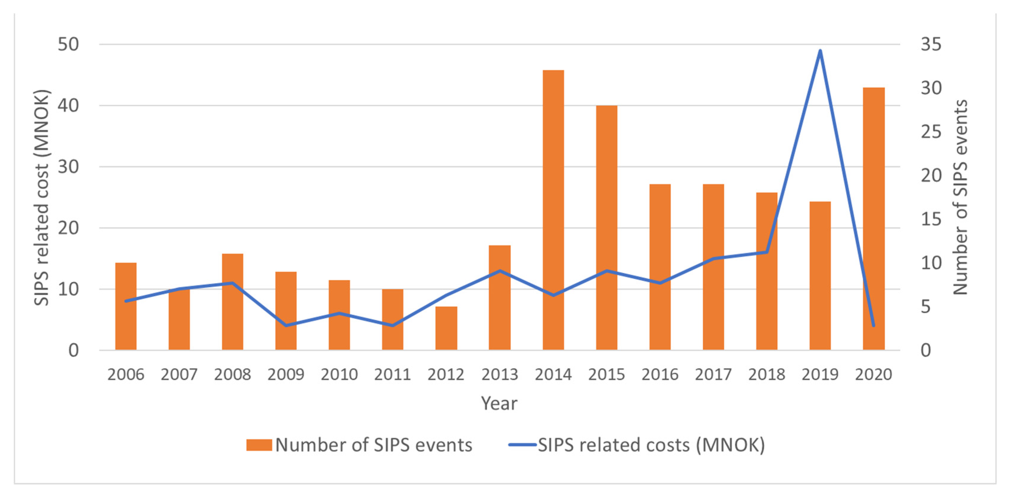
Figure 4 presents how the SIPS-related costs developed during the years 2006 to 2020, together with the total SIPS triggering events. As seen in the figure, there is a low correlation between the cost and the number of triggering events. In addition to the lack of information on the extent of the mitigating action, many of the triggering events relate to grid reconfiguration, which does not result in a direct SIPS-related operational cost.
6. Discussion
The naming conventions and terms used to relate to various solutions broadly placed under the SIPS umbrella complicate the development of new SIPS solutions and knowledge sharing. We believe that creating a common definition which can describe any type of SIPS has a value and is something which the industry should aim for. This paper, therefore, proposes such a definition where a SIPS is defined by its overall goal, its objective, and the specific means of which it acts. The standardization of terms, as proposed in Table 1, aims to further decrease the risk of misinterpretation.
To further facilitate knowledge sharing, this paper proposes a way to classify SIPSs by structuring the planning and operational phases. The proposed structure presented in Figure 1 is derived from analyzing and comparing the most common ways to group SIPS actions into general steps according to their similar objectives, i.e., SIPS arming, parameterizing, and triggering. While the proposed structure intends to overcome the downsides of previously proposed structures, it is likely that, with time, the proposed structure may also become obsolete. Each proposal for the structuring of SIPS phases and steps creates a framework to classify research and SIPS solutions which may, in colloquial language, be interpreted as creating a “box” in which to put the research. However, it is widely known that some of the most innovative and revolutionary results in science come from thinking outside of the “box”. Sticking hard to any of the proposed SIPS structures of research phases may hinder the innovation component of future research. Therefore, the authors of this paper would like to see the proposed structure not as a “box”, but more as a guideline on how current state-of-the-art SIPS research and current industry implementation can be classified and to provide a classification framework for future developed methods by sharing the principles of already existing ones.
It is interesting to note that, according to public literature, there are no SIPSs in Nordic countries used to prevent transient angle stability, which is an objective quite commonly described in the other reviewed literature. Whether this is due to this being included in the objective called stability in an unspecified sense has not been further investigated in this review. Additionally, the public literature available is from 2013, and whether this has changed is not known to the authors.
Although the statistics available from the Norwegian TSO give a sense of how often SIPSs are triggered in a country where SIPS solutions are deployed to quite a wide extent, it would be interesting to compare these figures to the corresponding data of other countries. Additionally, the value of the statistics of SIPS-related costs would increase if placed in relation to the gains of using SIPS in a cost–benefit assessment. For example, in relation to the savings by customers due to lower energy prices related to the use of SIPSs, or to the additional earnings of electricity producers (or increased governmental tax-related income). Investigating the views of other countries using SIPSs for socio-economic effects, and how they evaluate risk versus value, is also a subject worth further investigation.
We have found that using SIPSs to increase grid capacity is a practical solution to an escalating problem, given that the increased complexity must be considered. The growing use of SIPSs implies the need for more research in the area, and thus the need for the standardization of terms related to SIPSs.
7. Conclusions
It is important to realize that there are currently no common definitions or nomenclature for SIPSs. In this paper, we show clear examples of terms which can be interpreted in different ways. Thus, the terms proposed in this paper—Arming, Triggering, and Mitigative actions—are intended to support a standardized SIPS nomenclature. Furthermore, clear and consistent descriptions of the SIPS execution steps, here proposed as Arming, Parameterization, and Triggering, provide additional support for the development and implementation of SIPS solutions.
Although a common definition might be desirable, a practical way to obtain a clear understanding without the need for a global classification of SIPSs or potential sub-categories could be to define each SIPS by its goal, objective, and means. This would distinguish each control scheme by:
- Goal: Whether the SIPS is there to increase the power system’s reliability and/or capacity.
- Objective: Which phenomena or various type of stability and/or overloading the SIPS targets for mitigation by preventing the degradation of the power system’s technical performance, i.e., in cases of nonsecure pre-contingency system states or extreme contingencies.
- Means: Which Mitigative actions the SIPS can utilize.
There are, however, challenges in reaching an international consensus and standardizing nomenclature and definitions, but the values of these should not be underestimated. To support the integration of SIPSs in power systems worldwide, and to provide clarity in communication, standardized nomenclature has significant benefits. With several international interconnections already equipped with SIPSs, and a foreseen increase in SIPS use in general, the risk of misunderstanding, which ultimately may lead to faulty implementation, will escalate if different terminologies continue to be in use.
With increasing interest in SIPSs, the literature on SIPSs is also increasing. In order to maintain a comprehensive view of current accomplishments and relevant future topics, up-to-date literature reviews are needed. This paper provides one of such reviews with an emphasis on the classification of the current literature according to different SIPS features. From this classification, conclusions about well-established and areas of future research are drawn. One of these conclusions is that the most commonly considered SIPS mitigative action is load shedding for the purpose of addressing voltage instability and thermal overloading. However, more sophisticated SIPS actions, e.g., HVDC and FACTS control, var rescheduling and grid reconfiguration, are much less present in the literature, presenting a gap for future research.
Author Contributions
Section 2 Formal analysis, Conceptualization and writing-original draft preparation: E.H. Section 3 and Section 4 Formal analysis, Conceptualization and writing-original draft preparation: S.S. Section 5 Formal analysis, Conceptualization and writing-original draft preparation: E.H. and S.A. Full report writing-review and editing: E.H., S.S. and S.A. All authors have read and agreed to the published version of the manuscript.
Funding
This research received no external funding.
Institutional Review Board Statement
Not applicable.
Informed Consent Statement
Not applicable.
Data Availability Statement
Not applicable.
Acknowledgments
The authors would like to extend their gratitude to Statnett for the information shared on their SIPS.
Conflicts of Interest
The authors declare no conflict of interest.
References
- IEEE Std C37.250-2020; IEEE Guide for Engineering, Implementation, and Management of System Integrity Protection Schemes; IEEE: New York, NY, USA, 2020.
- Special Protection Schemes; Tech. Rep.; ENTSO-E: Brussels, Belgium, 2012.
- Network protection (Nätvärn), TR 02-05-11-01 utg 4; Teknisk Riktlinje; Svenska Kraftnät: Sundbyberg, Sweden, 2019. (In Swedish)
- System Protection Schemes in Power Networks, TB 187; CIGRE: Paris, France, 2001.
- A Proposed Framework for Coordinated Power System Stability Control, TB 742; CIGRE: Paris, France, 2018.
- Remedial Action Schemes (PRC-012-2); NERC: Atlanta, GA, USA, 2021.
- Remedial Action Scheme. Definition Development—Background and Frequently Asked Questions; NERC: Atlanta, GA, USA, 2014.
- Cardenas, J.; de Viñaspre, A.L.; López, A.; Ruiz, J.; Koksal, F.; Aycin, H.; Iliceto, F. Implementation of a Special Protection System (SPS) in the Interconnection between the Turkish and ENTSO-E Power Systems to Counteract Propagation of Major Disturbances. In Proceedings of the 3rd Annual Conference on Actual Trends in Development of Power System Protection and Automation, Saint Petersburg, Russia, 30 May–3 June 2011. [Google Scholar]
- Varghese, M.; Jin, L.; Ghosh, S.; Lin, G.; Pek, B. The CAISO experience of implementing automated remedial action schemes in energy management systems. In Proceedings of the 2009 IEEE Power Energy Society General Meeting, Calgary, AB, Canada, 26–30 July 2009; pp. 1–5. [Google Scholar]
- Iliceto, F.; Akansel, Ö.; Akdeniz, M.; Erikci, S.; Korkmaz, Y.Z.; Ravikumar, K.G. System Integrity Protection Schemes in the 400 kV Transmission Network of Turkey. In Proceedings of the 8th Annual Protection, Automation and Control World Conference, Wroclaw, Poland, 27–29 June 2017; p. 9. [Google Scholar]
- De La Quintana, A.; Palma-Behnke, R. Challenges for special protection systems in the Chilean electricity market. In Proceedings of the 2013 IEEE Power Energy Society General Meeting, Vancouver, BC, Canada, 21–25 July 2013; pp. 1–5. [Google Scholar]
- Hillberg, E.; Trengereid, F.; Breidablik, Ø.; Uhlen, K.; Kjølle, G.; Løvlund, S.; Gjerde, J.O. System Integrity Protection Schemes—Increasing Operational Security and System Capacity. In Proceedings of the 44th CIGRE Session, Paris, France, 26–31 August 2012. [Google Scholar]
- Valencia, F.; Palma-Behnke, R.; Ortiz-Villalba, D.; De La Quintana, A.; Rahmann, C.; Cifuentes, R. Special Protection Systems: Challenges in the Chilean Market in the Face of the Massive Integration of Solar Energy. IEEE Trans. Power Deliv. 2017, 32, 575–584. [Google Scholar] [CrossRef]
- Walseth, J.Å.; Eskedal, J.; Breidablik, Ø. Analysis of Misoperations of Protection Schemes in the Nordic Grid-1st of December 2005. Prot. Autom. Control. World 2010, 11, 28–33. [Google Scholar]
- Appendix 5 System Protection of the System Operation Agreement; ENTSO-E: Brussels, Belgium, 2013.
- Global Industry Experiences with System Integrity Protection Schemes (SIPS). IEEE Trans. Power Deliv. 2009, 25, 2143–2155.
- Pisani, C.; Giannuzzi, G.; Sattinger, W. Wide Area Monitoring and Protection System for Security and System Flexibility. In Proceedings of the CIGRE 2022 Symposium, Kyoto, Japan, 3–8 April 2022. [Google Scholar]
- Choi, D.H.; Lee, S.H.; Kang, Y.C.; Park, J.W. Analysis on Special Protection Scheme of Korea Electric Power System by Fully Utilizing STATCOM in a Generation Side. IEEE Trans. Power Syst. 2017, 32, 1882–1890. [Google Scholar] [CrossRef]
- Wang, Y.J.; Liu, C.W.; Liu, Y.H. A PMU based special protection scheme: A case study of Taiwan power system. Int. J. Electr. Power Energy Syst. 2005, 27, 215–223. [Google Scholar] [CrossRef]
- Arabzadeh, M.; Seifi, H.; Sheikh-El-Eslami, M.K. A new mechanism for remedial action schemes design in a multi-area power system considering competitive participation of multiple electricity market players. Int. J. Electr. Power Energy Syst. 2018, 103, 31–42. [Google Scholar] [CrossRef]
- Hillberg, E. Perception, Prediction, and Prevention of Extraordinary Events in the Power System; NTNU: Trondheim, Norway, 2016. [Google Scholar]
- Atighechi, H.; Hu, P.; Ebrahimi, S.; Lu, J.; Wang, G.; Wang, L. An effective load shedding remedial action scheme considering wind farms generation. Int. J. Electr. Power Energy Syst. 2018, 95, 353–363. [Google Scholar] [CrossRef]
- Maram, M.D.; Amjady, N. Event-based remedial action scheme against super-component contingencies to avert frequency and voltage instabilities. IET Gener. Transm. Distrib. 2014, 8, 1591–1603. [Google Scholar] [CrossRef]
- Xu, Y.; Dong, Z.Y.; Luo, F.; Zhang, R.; Wong, K.P. Parallel-differential evolution approach for optimal event-driven load shedding against voltage collapse in power systems. IET Gener. Transm. Distrib. 2014, 8, 651–660. [Google Scholar] [CrossRef]
- Liu, R.; Srivastava, A.K.; Bakken, D.E.; Askerman, A.; Panciatici, P. Decentralized State Estimation and Remedial Control Action for Minimum Wind Curtailment Using Distributed Computing Platform. IEEE Trans. Ind. Appl. 2017, 53, 5915–5926. [Google Scholar] [CrossRef]
- López, J.A.; Lu, C.N. Adaptable System Integrity Protection Scheme Considering Renewable Energy Sources Output Variations. IEEE Trans. Power Syst. 2020, 35, 3459–3469. [Google Scholar] [CrossRef]
- Zamani, M.A.; Beresh, R.; Cress, S.L. A PMU-augmented stability power limit assessment for reliable arming of special protection systems. Electr. Power Syst. Res. 2015, 128, 134–143. [Google Scholar] [CrossRef]
- Kamali, S.; Amraee, T. Blackout prediction in interconnected electric energy systems considering generation re-dispatch and energy curtailment. Appl. Energy 2017, 187, 50–61. [Google Scholar] [CrossRef]
- Panteli, M.; Crossley, P.A.; Fitch, J. Design of dependable and secure system integrity protection schemes. Int. J. Electr. Power Energy Syst. 2015, 68, 15–25. [Google Scholar] [CrossRef]
- Singh, V.K.; Govindarasu, M. Decision Tree Based Anomaly Detection for Remedial Action Scheme in Smart Grid using PMU Data. In Proceedings of the 2018 IEEE Power Energy Society General Meeting (PESGM), Portland, OR, USA, 5–9 August 2018; pp. 1–5. [Google Scholar]
- Derafshian, M.; Amjady, N.; Dehghan, S. Special protection scheme against voltage collapse. IET Gener. Transm. Distrib. 2016, 10, 341–351. [Google Scholar] [CrossRef]
- Morais, R.M. On the suitability, requisites, and challenges of machine learning [Invited]. J. Opt. Commun. Netw. 2021, 13, A1–A12. [Google Scholar] [CrossRef]
- Lwakatare, L.E.; Raj, A.; Crnkovic, I.; Bosch, J.; Olsson, H.H. Large-scale machine learning systems in real-world industrial settings: A review of challenges and solutions. Inf. Softw. Technol. 2020, 127, 106368. [Google Scholar] [CrossRef]
- Ahmad, T.; Madonski, R.; Zhang, D.; Huang, C.; Mujeeb, A. Data-driven probabilistic machine learning in sustainable smart energy/smart energy systems: Key developments, challenges, and future research opportunities in the context of smart grid paradigm. Renew. Sustain. Energy Rev. 2022, 160, 112128. [Google Scholar] [CrossRef]
- Abedini, M.; Sanaye-Pasand, M.; Azizi, S. Adaptive load shedding scheme to preserve the power system stability following large disturbances. IET Gener. Transm. Distrib. 2014, 8, 2124–2133. [Google Scholar] [CrossRef]
- Amraee, T.; Ranjbar, A.M.; Feuillet, R.; Mozafari, B. System protection scheme for mitigation of cascaded voltage collapses. IET Gener. Transm. Distrib. 2009, 3, 242–256. [Google Scholar] [CrossRef]
- Tang, J.; Liu, J.; Ponci, F.; Monti, A. Adaptive load shedding based on combined frequency and voltage stability assessment using synchrophasor measurements. IEEE Trans. Power Syst. 2013, 28, 2035–2047. [Google Scholar] [CrossRef]
- Wang, Y.; Pordanjani, I.R.; Li, W.; Xu, W.; Vaahedi, E. Strategy to minimise the load shedding amount for voltage collapse prevention. IET Gener. Transm. Distrib. 2011, 5, 307–313. [Google Scholar] [CrossRef] [Green Version]
- Calvo, J.L.; Tindemans, S.H.; Strbac, G. Incorporating failures of System Protection Schemes into power system operation. Sustain. Energy Grids Netw. 2016, 8, 98–110. [Google Scholar] [CrossRef] [Green Version]
- Ballal, M.S.; Kulkarni, A.R.; Suryawanshi, H.M. Methodology for the improvements in synchrophasor based System Integrity Protection Schemes under stressed conditions. Sustain. Energy Grids Netw. 2021, 26, 100465. [Google Scholar] [CrossRef]
- Rahimi Pordanjani, I.; Askarian Abyaneh, H.; Sadeghi, S.H.H.; Mazlumi, K. Risk reduction in special protection systems by using an online method for transient instability prediction. Int. J. Electr. Power Energy Syst. 2010, 32, 156–162. [Google Scholar] [CrossRef]
- Sass, F.; Sennewald, T.; Westermann, D. Automated Corrective Actions by VSC-HVDC-Systems: A Novel Remedial Action Scheme. IEEE Trans. Power Syst. 2020, 35, 385–394. [Google Scholar] [CrossRef]
- Setareh, M.; Parniani, M. Sensitivity-based Optimal Remedial Actions to Damp Oscillatory Modes Considering Security Constraints. Int. J. Electr. Power Energy Syst. 2022, 135, 107580. [Google Scholar] [CrossRef]
- Weckesser, T.; Jóhannsson, H.; Østergaard, J. Real-Time Remedial Action Against Aperiodic Small Signal Rotor Angle Instability. IEEE Trans. Power Syst. 2016, 31, 387–396. [Google Scholar] [CrossRef] [Green Version]
- Yang, J.-S.; Liao, C.-J.; Wang, Y.-F.; Chu, C.-C.; Lee, S.-H.; Lin, Y.-J. Design and Deployment of Special Protection System for Kinmen Power System in Taiwan. IEEE Trans. Ind. Appl. 2017, 53, 4176–4185. [Google Scholar] [CrossRef]
- Zbunjak, Z.; Kuzle, I. System Integrity Protection Scheme (SIPS) Development and an Optimal Bus-Splitting Scheme Supported by Phasor Measurement Units (PMUs). Energies 2019, 12, 3404. [Google Scholar] [CrossRef] [Green Version]
- Mallikarjuna, B.; Maddikara, J.B.R. Synchrophasor measurement assisted system integrity protection scheme for smart power grid. J. Control. Autom. Electr. Syst. 2020, 31, 207–225. [Google Scholar] [CrossRef]
- Wang, P.; Govindarasu, M. Multi agent-based attack resilient system integrity protection for smart grid. IEEE Trans. Smart Grid 2020, 11, 3447–3456. [Google Scholar] [CrossRef]
- Glossary of Terms Used in NERC Reliability Standards; NERC: Atlanta, GA, USA, 2021.
- Appendix 1 Definitions of the System Operation Agreement; ENTSO-E: Brussels, Belgium, 2013.
- Defense Plans against Extreme Contingencies, TB 316; CIGRE: Paris, France, 2007.
- Rajalwal, N.K.; Ghosh, D. Recent trends in integrity protection of power system: A literature review. Int. Trans. Electr. Energy Syst. 2020, 30, e12523. [Google Scholar] [CrossRef]
- Annex Operational Security of the System Operation Agreement; ENTSO-E: Brussels, Belgium, 2019.
- Guidelines for Provisions for System Responsibility in the Power System (Retningslinjer for Fos) § 21. Available online: https://www.statnett.no/globalassets/for-aktorer-i-kraftsystemet/systemansvaret/retningslinjer-fos/systemansvaret---retningslinjer-fos--21.pdf (accessed on 3 March 2022). (In Norwegian).
- Appendix 2 Operational Security Standards of the System Operation Agreement; ENTSO-E: Brussels, Belgium, 2013.
- How We Work to Increase Transfer Capacity (Så Arbetar Vi För Att Öka Överföringskapaciteten); Svenska Kraftnät: Sundbyberg, Sweden, 2022. (In Swedish)
- Report from System Responsible (Rapport fra Systemansvarlig Om Kraftsystemet i Norge) 2020; Statnett: Oslo, Norway, 2020. (In Norwegian)
- Yearly Reports from System Responsible (Årsrapporter fra Systemansvarlig). Available online: https://www.statnett.no/for-aktorer-i-kraftbransjen/systemansvaret/arsrapporter-fra-systemansvarlig/ (accessed on 3 March 2022). (In Norwegian).
Figure 1.
SIPS planning and operation phases and execution steps.

Figure 2.
Time frame of power system-related phenomena, based on [21].
Figure 2.
Time frame of power system-related phenomena, based on [21].

Figure 3.
Number of load shedding and generation rejection events as well as SIPS-related costs for the years 2015–2020, based on information available in [58].
Figure 3.
Number of load shedding and generation rejection events as well as SIPS-related costs for the years 2015–2020, based on information available in [58].

Figure 4.
SIPS-related costs (based on information available in [58]) and total number of SIPS triggers (input provided by Statnett).
Figure 4.
SIPS-related costs (based on information available in [58]) and total number of SIPS triggers (input provided by Statnett).


Table 1.
List of terms related to the design of System Integrity Protection Schemes.
| Proposed Term | Description and Comments | Other Terms |
|---|---|---|
| (dis-)Arming | Enables (disables) the possibility of SIPSs providing mitigative actions. SIPSs may be always armed or armed only during certain system conditions. | Activation; In-operation; Sensitizing |
| Arming criteria | System condition providing decision basis for when a SIPS should be armed, e.g., power flow levels, or the availability of assets. | Requirements |
| Triggering | If armed, triggering will result in mitigative actions being initiated. | Activation; Operation; Mitigation |
| Triggering criteria | Monitored system conditions where SIPS mitigative actions are required. Typically based on the monitoring of discrete signals (e.g., breaker status) or continuous dynamic system response (e.g., frequency). | Threshold; Contingency; Phenomena |
| Mitigative actions | Actions initiated by SIPS triggering, e.g., the rejection/shedding of generators or loads, or grid reconfiguration. | Remedial; Corrective; Protective; Control |
| Mitigative action extent | Quantity of SIPS action determined based on system conditions and on the needs to fulfill the SIPS objective in case the triggering criteria are met. Could be quantified in: MW, Mvar, etc. | Volume; Level |
Table 2.
SIPS literature classification part 1.
| Mitigative Action Type | |||||||
|---|---|---|---|---|---|---|---|
| SIPS Objective | Load Shedding | Generation Rejection | Generation Rescheduling | Var Rescheduling | HVDC Control | FACTs Control | Grid Re-Configuration |
| Voltage stability | [22,23,24,31,35,36,37,38] | [37] | [42] | ||||
| Small signal angle stability | [8,10,22,26,43] | [8,10] | [26,43,44] | [43] | |||
| Transient angle stability | [8,10,19,26,27,40] | [8,10,18,19,27,41] | [26,40] | [27] | [18] | [28] | |
| Frequency stability | [8,10,11,23,35,37,45] | [8,10,11] | [11] | [37] | |||
| Component overload | [11,20] | [11,14,20,25] | [11,13,25,39] | [42] | [14] | ||
Table 3.
SIPS literature classification part 2.
| Detection Method | Decision System | |||||
|---|---|---|---|---|---|---|
| SIPS Objective | Event-Based | Response-Based | Local | Distributed | Centralized | |
| Limit | Trajectory | |||||
| Voltage stability | [22,23,24,31,36,38] | [35,37,42] | [35,42] | [22,23,24,31,36,37,38] | ||
| Small signal angle stability | [22] | [8,10,26,44] | [43] | [8,10,44] | [22,26,43] | |
| Transient angle stability | [18,27,40] | [8,10,26,28] | [19,40,41] | [18,41] | [8,10] | [19,26,27,28,40] |
| Frequency stability | [23,45] | [8,10,11] | [35,37] | [11,35] | [8,10] | [23,37,45] |
| Component overload | [14,20,39] | [11,14] | [13,25,42] | [11,13,39,42] | [25] | [14,20] |
Table 4.
Classification of SIPS 1 integrated in the Nordic power system, based on information available in [3,15].
| Mitigative Action Type | |||||||
|---|---|---|---|---|---|---|---|
| SIPS Objective | Load Shedding | Generation Rejection | Generation Rescheduling | Var Rescheduling | HVDC Control | FACTs Control | Grid Re- Configuration |
| Voltage stability | X | X | O | O, X | |||
| Small signal angle stability | X | ||||||
| Transient angle stability | |||||||
| Frequency stability | O | O2 | O | O, X | O | ||
| Component overload | X | X | X | X | |||
| Stability (undefined) | X | X | X | X | X | ||
1 Detection method for triggering: event-based (X) and response-based (O). 2 Additionally, including the mitigating action type: generation start-up.
Publisher’s Note: MDPI stays neutral with regard to jurisdictional claims in published maps and institutional affiliations. |
© 2022 by the authors. Licensee MDPI, Basel, Switzerland. This article is an open access article distributed under the terms and conditions of the Creative Commons Attribution (CC BY) license (https://creativecommons.org/licenses/by/4.0/).
Share and Cite
MDPI and ACS Style
Stanković, S.; Hillberg, E.; Ackeby, S. System Integrity Protection Schemes: Naming Conventions and the Need for Standardization. Energies 2022, 15, 3920. https://0-doi-org.brum.beds.ac.uk/10.3390/en15113920
AMA Style
Stanković S, Hillberg E, Ackeby S. System Integrity Protection Schemes: Naming Conventions and the Need for Standardization. Energies. 2022; 15(11):3920. https://0-doi-org.brum.beds.ac.uk/10.3390/en15113920
Chicago/Turabian StyleStanković, Stefan, Emil Hillberg, and Susanne Ackeby. 2022. "System Integrity Protection Schemes: Naming Conventions and the Need for Standardization" Energies 15, no. 11: 3920. https://0-doi-org.brum.beds.ac.uk/10.3390/en15113920
Note that from the first issue of 2016, this journal uses article numbers instead of page numbers. See further details here.