
New Integrated Energy Solution Idealization: Hybrid for Renewable Energy Network (Hy4REN)


1
Instituto Superior Técnico, CERIS, Universidade de Lisboa, 1049-004 Lisboa, Portugal
2
Innoenergy Masters Energy Technologies (ENTECH), Uppsala Universitet, 75236 Uppsala, Sweden
3
Innoenergy Masters Energy Technologies (ENTECH), Grenoble INP—ENSE3, 38031 Grenoble, France
*
Author to whom correspondence should be addressed.
Energies 2022, 15(11), 3921; https://0-doi-org.brum.beds.ac.uk/10.3390/en15113921
Submission received: 26 April 2022
/
Revised: 15 May 2022
/
Accepted: 23 May 2022
/
Published: 26 May 2022
(This article belongs to the Special Issue Innovation in Sustainable Energy Component, Concept and System Design)
Abstract
:A review of different energy components is detailed, as a baseline of fundamentals for the new integrated energy concept idealization. This innovative solution is a Hybrid for Renewable Energy Network (Hy4REN) based on well-studied elements to produce the best final solution. This proposal has the objective of improving energy system sustainability, facing fossil fuel and climate change restrictions, and increasing energy network flexibility. The most mature energy storage technology, pumped hydropower energy storage (PHES), is used to support both the grid connection and stand-alone modes, as an integrated hybrid energy system. The hybrid system idealization is modular and scalable, with a complementary nature among several renewables, using sea water in offshore mode to build an integrated solution. By evaluating a variety of energy sources, complemented with economic analysis, the benefits associated are evidenced using this sustainable methodology based only on renewable sources. Combined production of hydropower, using sea water, with pumped storage and water hammer events to create potential energy to supply hydropower in a water loop cycle, without consuming electrical energy, is explored. Other renewable sources are also integrated, such as floating solar PV energy and an oscillating water column (OWC) with coupled air-venting Wells and wind turbines, all integrated into the Hy4REN device. This complementarity of available sources allows us to improve energy storage flexibility and addresses the energy transition toward net-zero carbon emissions, inducing significant improvements in the sustainability of the energy network as a whole.
1. Brief Introduction
A modern and more flexible type of hydropower is a desired energy innovation concept, demonstrating how hydro solutions can help countries and regions to meet their renewable energy targets working towards their decarbonization goals. A set of innovative hydro technologies covering different types and sizes of hydropower stations allows the integration of a scalable smart power plant based on artificial intelligence (AI) tools, aiming to improve the flexibility of services, the average annual system efficiency, through the complementarity of available resources, demand requirements, and weather forecasting. For the electric system, this is of the utmost importance for the system’s efficiency as well as for energy management, improving its reliability against climate change, refining energy production flexibility, and contributing to the energy transition, in which the aim is to attain net-zero carbon emissions by 2050.
The integration of well-proven energy source technologies will be the best optimized future solution. Additionally, the industry is seeing the potential of hydrogen technology, with the goal of, by 2025, producing 650 tonnes/day of green hydrogen [1,2,3,4].
In April 2022, the Iberian electricity market (Mibel) registered a sharp drop in the wholesale price of electricity, with contracted production recording an average daily price of 85.19 euros per megawatt hour (MWh). As a result of strong wind production, with the absence of fuels sources use, above all, left more space for hydropower plants to set the closing price for electricity. The minimum hourly price was 6 euros per MWh (accumulating the effects of high solar and wind production simultaneously), while the maximum price registered was 148 euros per MWh.
Underpinned by a global shift of regulators, investors, and consumers toward decarbonization, renewables and hydrogen are receiving unprecedented interest and investment. As of the beginning of 2021, over 30 countries had released hydrogen roadmaps. The energy sector is still dominated by fossil fuels, being the largest contributor to greenhouse gas emissions. Nations need reliable sources of energy to power cities. It is urgent to switch to sustainable energy. Despite some progress, universal access to clean, affordable, and reliable energy, is on track to meet our climate objectives, and to achieve the desired Sustainable Development Goal. Clean energy is a smart investment, and there is growing momentum for carbon neutrality and to make it a political and asset priority [2]. It is necessary to accelerate sustainable energy innovations as well as to explore all the opportunities of available renewable sources as integrated solutions, as part of the wider energy transition of countries [3]. Sustainability is about more than lowering emissions, meaning an industry that is commercially viable, endlessly innovative, and highly competitive. Hence, supporting sustainable energy innovations allows to provide industry risk-free, pioneering new technologies, reducing energy costs, increasing system performance, decreasing greenhouse gas (GHG) emissions, creating jobs, and increasing competitiveness.
The current energy crisis has changed the world paradigm of energy consumption and how to obtain it. As such, countries have intensified the search for new solutions. With a total of 3800 km and a power of 1.8 GW, Morocco will extend, together with Great Britain, a subsea cable with which it intends to supply energy to more than 7 million homes. The United Kingdom has reached an agreement with Morocco to obtain electricity from the inexhaustible photovoltaic energy available to the African country, with a budget of €18.5 billion. The planned PV and wind power plants, near the town of Tan-Tan, off the Canary Islands, and will have a floor area of more than 1500 km2. A production capacity of 10.5 GW per year is planned, of which 7.5 GW will come from solar energy, while 3 GW will derived from wind energy. In addition, the project is also contemplating the construction of batteries for energy storage with a capacity of 20 GWh [4]. It is worth mentioning that this once again corroborates the new integration project design proposed herein.
2. Baseline Studies and Fundamentals to Support the New Concept
2.1. Pumped Hydropower Energy Storage (PHES)
The challenge of energy mix will impose greater demands on hydropower to provide flexibility and reliability in power services, as well as viable solutions to adapt to supply and demand in a harmonized, balanced way. New technologies will help integrate intermittent renewables such as wind and solar power into the European power system. Variable turbomachines’ speed also provides an added degree of flexibility, varying the rotational speed of reversible units and using this to enhance grid services in both pumping and generation modes. In particular, variable speed pump-turbines enable power regulation and load even in pumping mode. Variable speed pumped storage projects can operate in a wider range, with higher efficiency and quicker response time in both modes of operation (pumping and turbine modes).
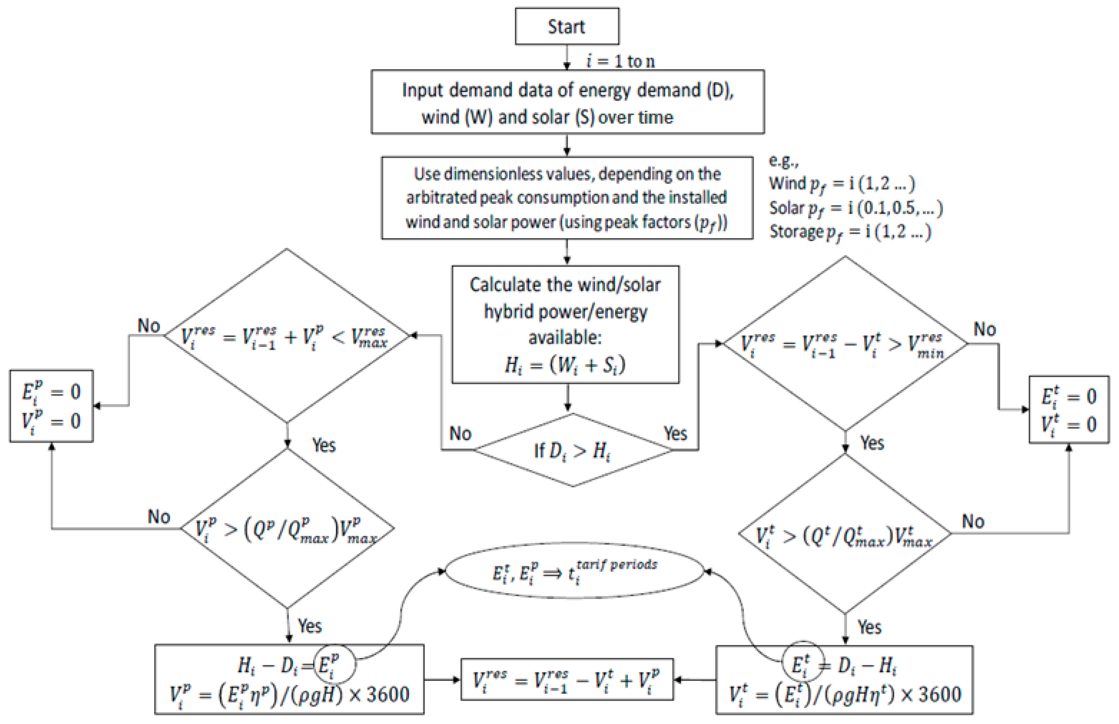
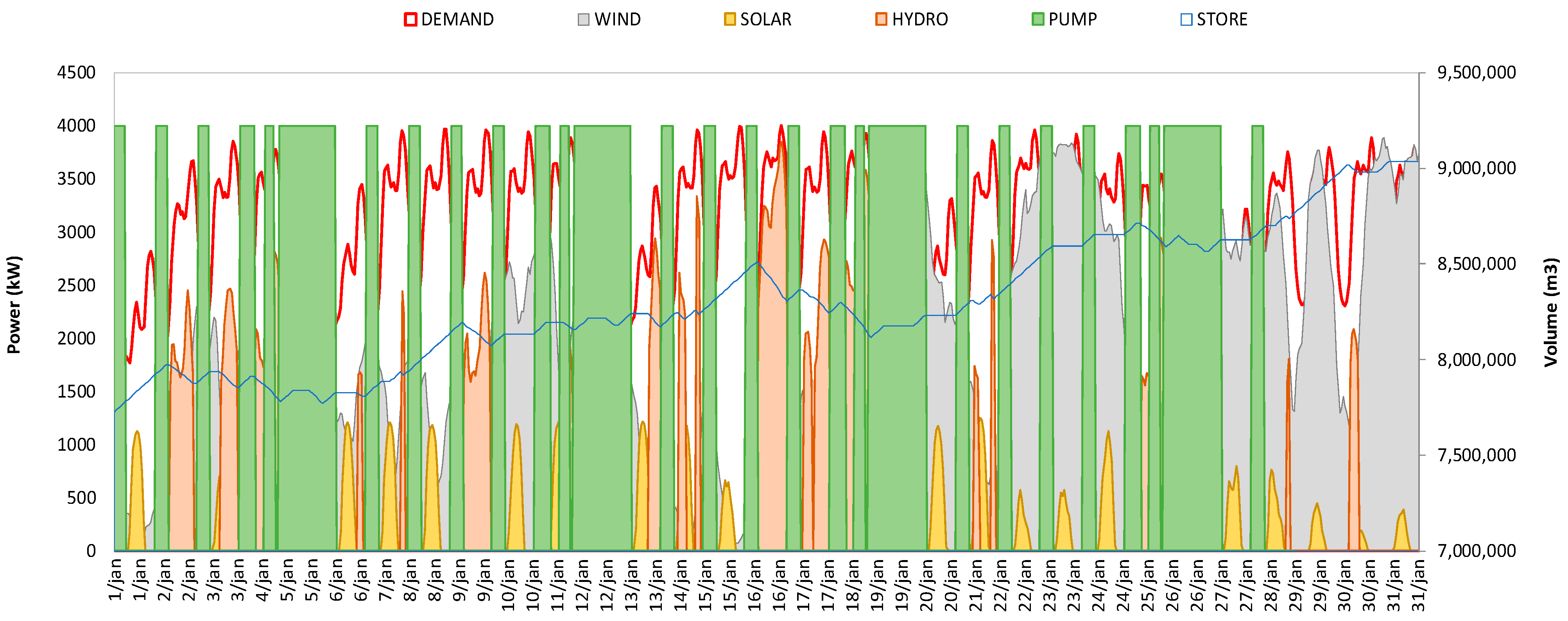
An energy generation system based on wind and solar technologies, together with pumped hydropower storage schemes, is defined, predicting how much renewable power and storage capacity should be installed to satisfy renewables-only generation solutions. The results demonstrate the pumped hydro storage based on renewable energy source integration is technically an ideal solution to achieve energy autonomy, to increase energy system flexibility, to combine with desalination and hydrogen production, and to contribute to energy solution reliability (Figure 1, Figure 2 and Figure 3).
Nowadays, hydropower plays an important role as a natural renewable source with pumped storage and will become even more important in the coming decades, since hydropower can be a catalyzer for the energy transition in Europe and around the world, satisfying the nexus of available water-energy-food [1,2,3,4,5,6,7,8,9]. The proposal for this transition is quite ambitious, and it intends to achieve a decarbonized and stable future, through an efficient way, both in safety and in security. The intermittent nature of wind and solar power presents a difficulty for matching energy production and demand. Making use of hydropower can provide support for the integration of these intermittent sources into the grid, with its capabilities of storing energy in a green and sustainable way in addition to its ease in energy production. These characteristics will be more and more important in the future for the energy transition to thrive worldwide, especially: (a) increasing the output of energy from hydropower, by implementing environmentally conscious, multifunctional hydropower plants and making use of the available hidden hydropower potential; (b) by adapting and optimizing new infrastructures, the production of energy becomes more flexible, and by combining with some innovative solutions, the environmental impact can also be reduced (Figure 2); and (c) expanding storage by intensification of available sources (such as using available water from the sea) and the construction of a compact integrated solution for a stand-alone answer, or new reservoirs, which have to ensure not only elastic energy supply but also support to mobility, sustainable agriculture, and facing water scarcity due to the effects of climate change. Therefore, a hybrid system with several renewable energy resources can work in a complementary way, in integrated and flexible uses in the electricity production system and water-energy management (Figure 3) toward a circular economy, energy transition, and climate change adaptation. Pumped hydropower storage (PHS) accounts for up to 80% of installed global energy storage capacity and retains advantages in lifespan cost, levels of sustainability, and complementarity of resources, as shown in Figure 3. The existing power of pumped storage capacity supports power grid stability, as significant water-pool batteries through water storage in tanks, reservoirs, or air vessels with potential energy, reducing overall system costs and energy sector emissions [9].
2.2. Water-Air Transient Technology for Energy Storage (WATT4ES)
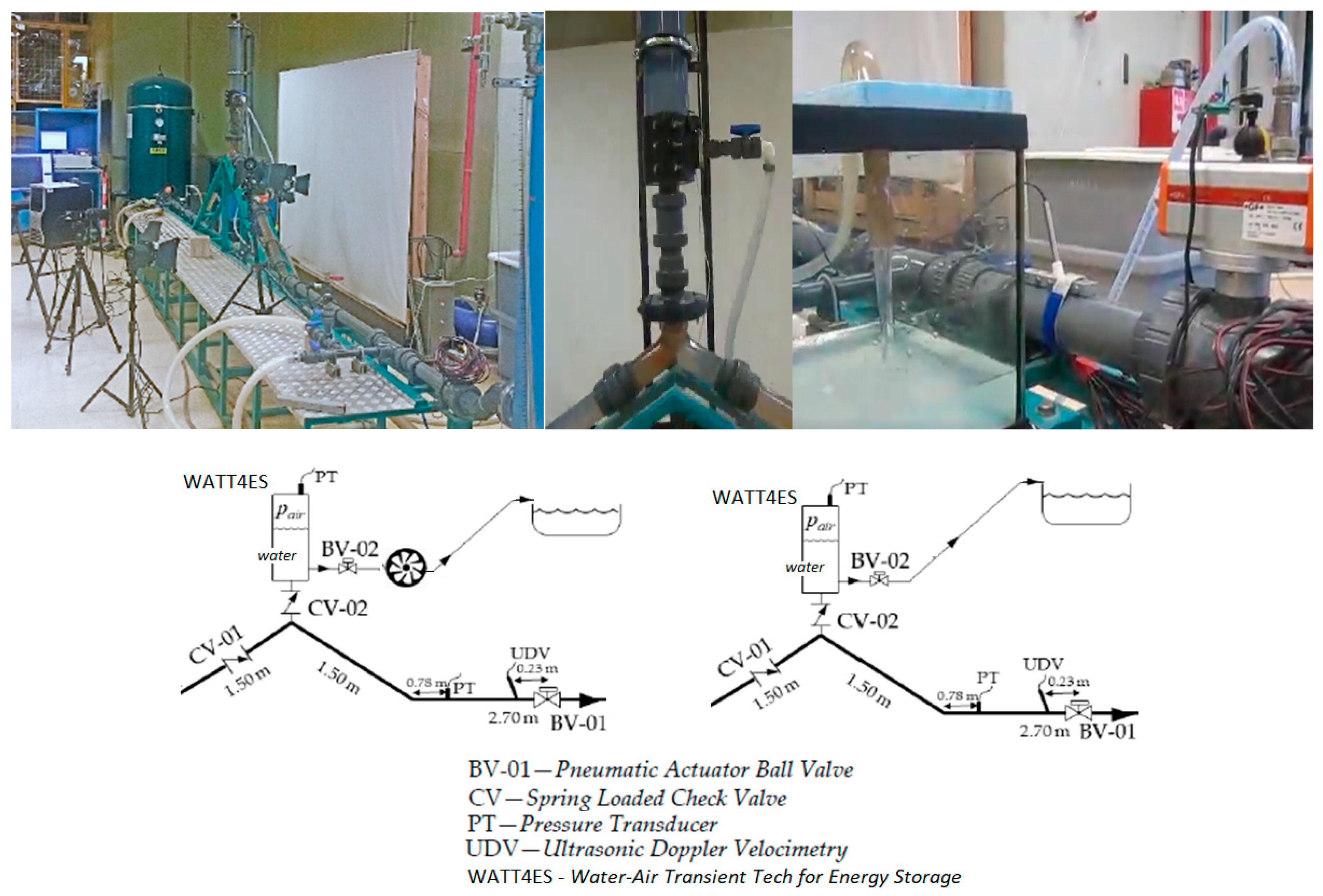
Water-Air Transient Technology for Energy Storage is based on the well-known technology of the hydram, which uses the available power of flowing water to pump itself, or to store energy in a surge tank with two-phase flows (water and air). For the hydraulic ram pump, commonly referred to as a hydram, the main principle is based on utilizing the natural power of a fast valve closure, not requiring an external energy supply to operate. This process works on a principle called “water hammer”, where a huge potential energy by upsurge is induced by a valve maneuver. This valve is a waste valve, because of a constant open and closure induces an upsurge with part of the flow storage in WATT4ES, placed above, and another small part continues flowing through the waste valve to the collected bottom reservoir to be recirculated again. A single hydram can lift water up to 200 m vertically due to upsurge effects and supplies roughly 20 m3 of water per day depending on the flow volume used. Hydrams are unique for their simplicity, durability, and virtually cost-free operation. WATT4ES is based on the hydram principle but is more focused on the potential energy storage capacity in terms of volume and pressure. WATT4ES uses the compressibility of the air inside the vessel storage, increasing the pressure by transient flow conditions. Hydrams are particularly useful in remote areas with significant differential levels of topography, and they can be created in an offshore, nearshore, or onshore solution where water can be pumped without consuming electricity to the higher points far from the water source [10,11]. The hydram pump is placed downstream of a water source and connected by a drive pipe. Gravity feeds the water down the drive pipe to a downstream valve, which with a continuous open/close maneuver drives the flow to the surge vessel WATT4ES operating as a pump storage system, isolated by a check-valve from the gravity drive pipe (Figure 4).
Due to the increasing consciousness about the adverse impacts of global warming and climate change and the desire for sustainable technology, the interest in hydram for water supply purposes and potential energy generation has come to be considered again. Studies about the effectiveness of hydram implementation and the effect of the stroke valve design on the flow rate of water have been developed. There were three methods used in this previous study: (i) experimental evaluation of hydram; (ii) experimental evaluation of the adjustable waste valve; and (iii) computational simulation of the adjustable waste valve. The adjustable waste valve was designed and manufactured for the experiments, and modeled for simulation at the IST lab. The hydram is suitable to be installed as a pump that uses the upsurge effects, without consuming energy, as potential energy storage since the flow conditions can attain a higher pressure than that of the inlet water level.
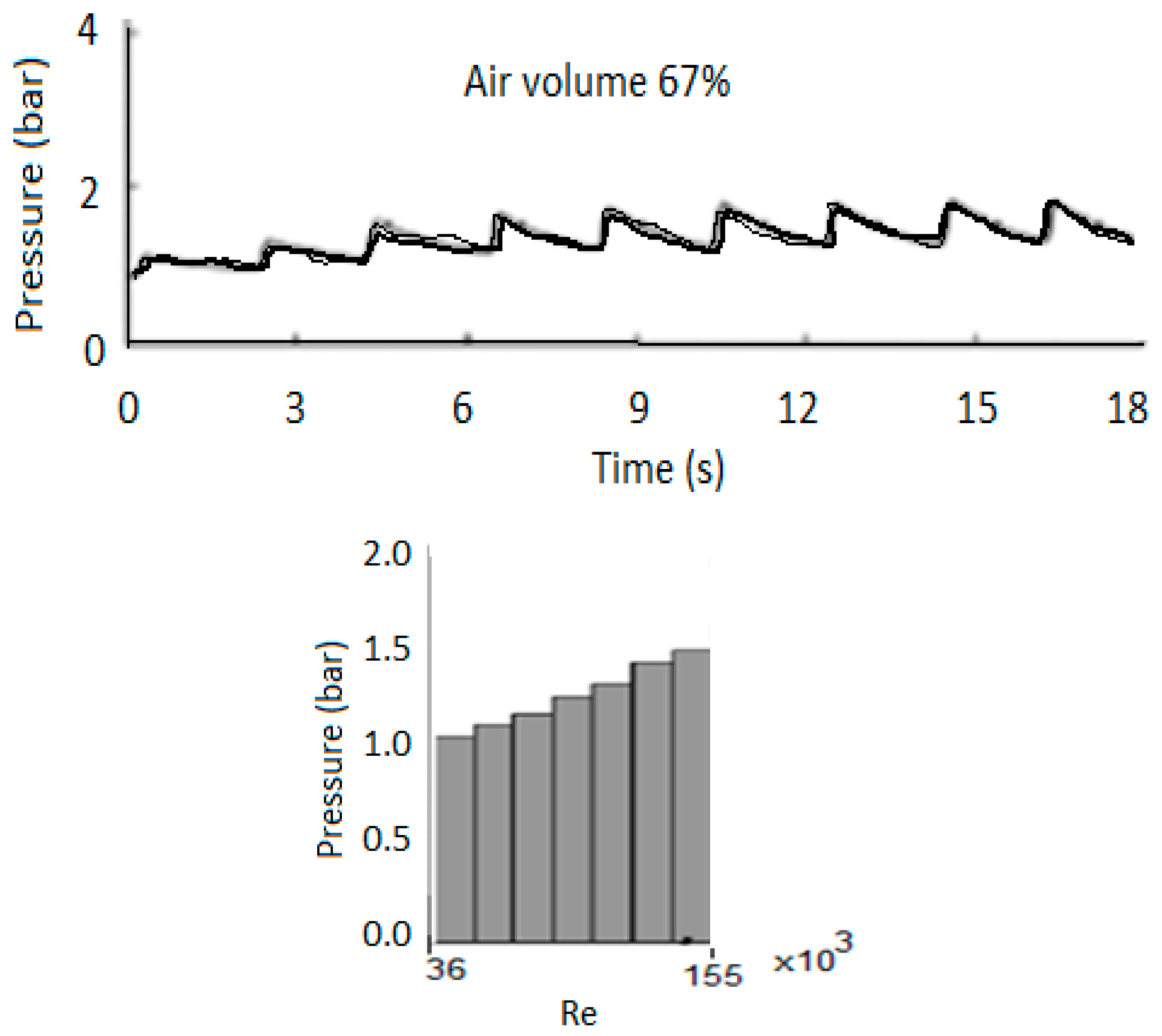
In recent studies developed at Instituto Superior Técnico Lisboa (IST)—Hydraulic Laboratory [10], hydropower still has the biggest share due to the compatibility, reliability, and flexibility (Figure 5) of the solutions that it can offer. This study presents one such technology recently examined based on a transient-flow induced compressed air energy storage (TI-CAES) system, which takes advantage of a compressed air vessel (similar to WATT4ES). WATT4ES can produce the required pressure head, by compressing the air, to be used in either hydropower generation using a water turbine in a gravity system or to be exploited as a pumping system. The results show a controlled behavior of the system in storing the pressure surge as compressed air inside a vessel. Considerable power values are achieved as well. Higher power values are attained for bigger air volumes [10]. The induced transients in the compressed air allow a constant outflow discharge characteristic, making the energy storage available in the WATT4ES to be used as a pump hydropower energy storage solution (Figure 6). In Table 1, the main parameters for operation of a 4.7 m3 vessel are presented based on experiments. The volume of air varies along with the pressure, and the energy storage capacity in the device is calculated.
In this new conceptual idea of energy storage/recovery using transient flow, it is induced in the system by creating a water hammer event, which has been widely studied and addressed in the literature from different aspects, providing enough data to implement in this new conceptualization idea. For this purpose, experimental data are collected in a system composed of a water pipeline, a compressed air vessel (WATT4ES). The results of experimental investigations are used to assess three operations: (a) generating energy using a water turbine; (b) pumping water using the stored pressure inside the entrapped air; and (c) an energy storage solution in a water-air vessel (Figure 5 and Figure 6).
2.3. Solar PV
Solar energy generation capacity has been increasing significantly in the past decade with a contribution of almost 2.4% to the global electricity supply in 2018, which is predicted to increase to 22% in 2025, with potentially up to 70% in 2050 [11,12,13]. However, development of large utility-scale PV system installations is limited due to (i) the cost and availability of favorable land areas, (ii) the decrease in efficiency at high operating PV cell temperature, and (iii) potential environmental impacts, including for biodiversity.
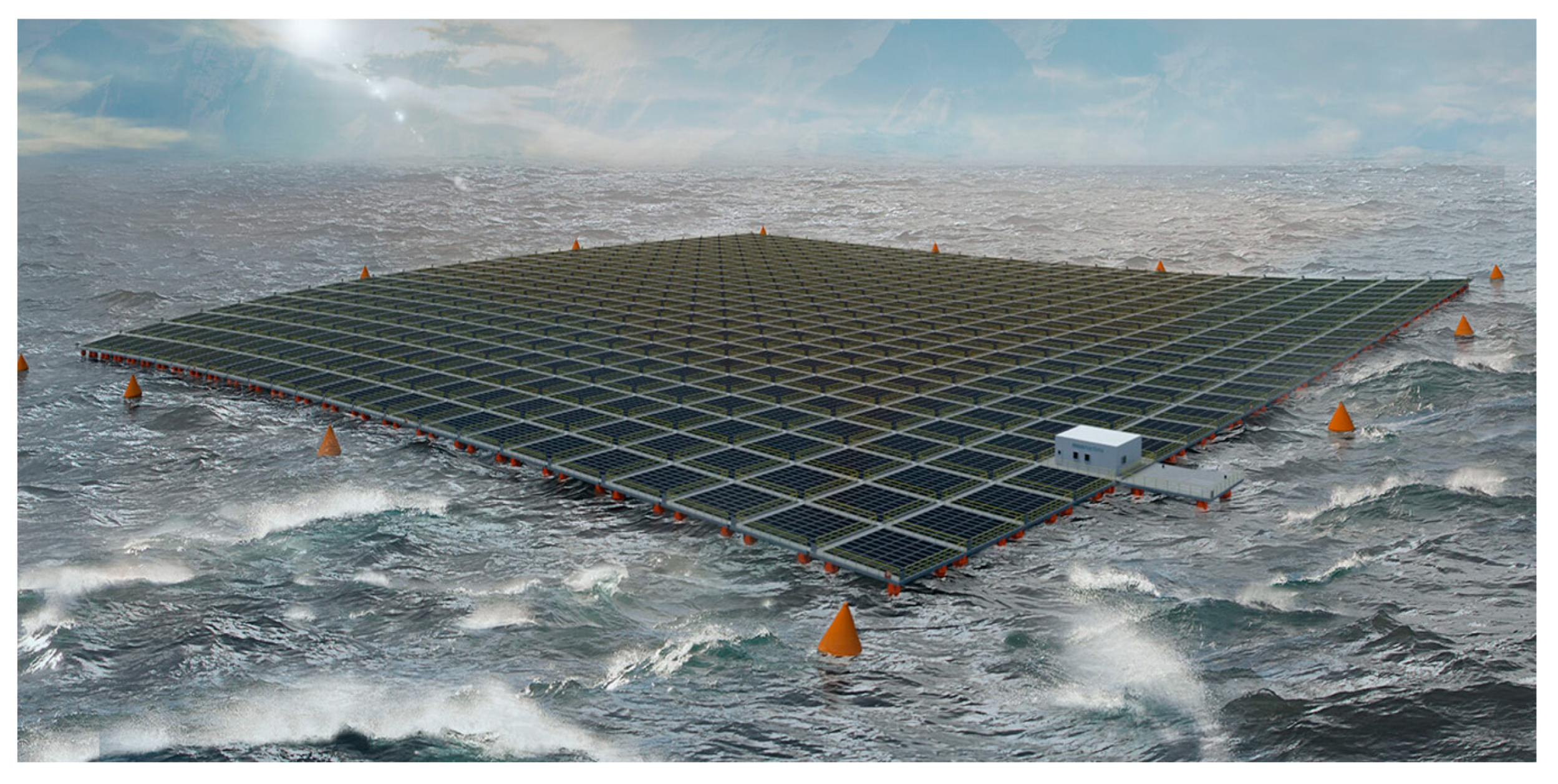
Therefore, a strong motivation is emerging for introducing both building-integrated PV (BIPV) and floating PV (FPV) systems, both onshore and offshore on islands, boats, or floating solutions. So, the aim of this research is focused on FPV, which presents several advantages: (i) reduction in land use, which may be otherwise designated for agricultural use; (ii) achieving a natural cooling potential of the water body may enhance PV performance, due to a higher level of wind speeds offshore, with the water surface as a regular cooling system; (iii) a lower amount of obstacles causing shading loss; (iv) a lower amount of dust compared with land-based PV (LBPV) systems; (v) more than 50% of the entire world population lives near an oceanic coast, where energy is needed, and thus an FPV system installed in the sea can be conveniently located to supply energy to these regions and harbors; and (vi) the extracted energy from FPV systems could be a great supply for offshore platforms and ships, contributing to the global greenhouse gas reduction, and can, at same time, be used for hydrogen production and desalination, when necessary. An optimal FPV is supposed to be used as a modular solution, in a flexible way, with robustness, safety, an optimum supportive structure size, and simplicity of installation, and is an economically viable solution [11,12,13].
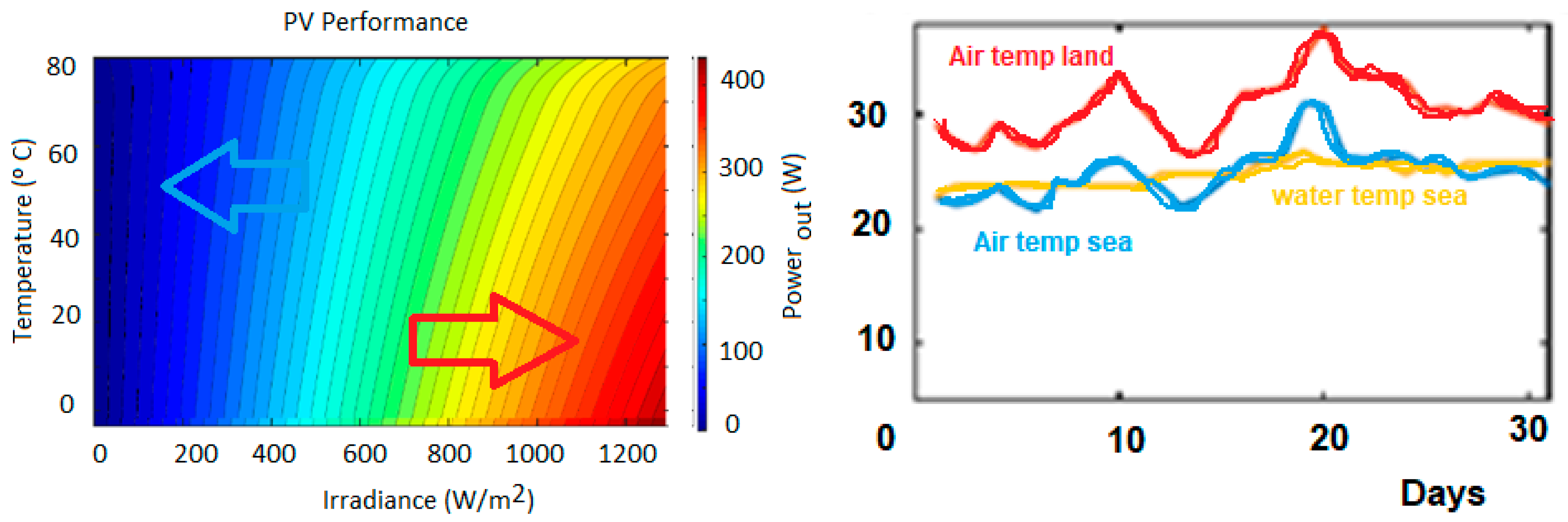
Recent developments show the creation of floating PV (FPV) solutions, with simulation modeling allowing the performance comparison of a photovoltaics system on land and at sea (Figure 7). The irradiation on a tilted surface for a floating system is calculated considering the tilt angle, which is affected by the sea waves. Moreover, the temperature is estimated based on heat transfer theory and the natural cooling system for both floating and land-based photovoltaic systems. Two different locations were simulated: one at Utrecht University campus in the Netherlands and the other one in the North Sea. Energy yield is calculated for both weather conditions. The results show that the relative annual average output energy is about 13% higher at sea compared with on land (Figure 8). However, in some months, this relative output energy increases to an up to 18% higher energy yield at sea [14,15,16,17,18,19].
The global tilted irradiation (GTI) surface determines the power generated by the PV panel. Then the maximum power under ideal conditions is proportional to the calculated energy per meter of the wavefront, and the wave energy of a harmonic wave is given by:
where λ is the wave length, H is the wave height, and T is the wave period.
Pideal = ρg2H2T/(32π) (W/m) and E = ρgH2λ/8 (J/m)
The energy yield over a certain time period ∆tn is computed as a product of output power and converter efficiency.
EY = (ηconv × ΣPnΔtn) × 10−3
During 24 h of a day, where EY is the generated energy yield in kWh, Pn is the power in W for the time resolution, ∆tn, in hours, and the sum of the N number of time intervals (1440 for 24 h), n the time interval index, and ηconv is the efficiency of the converter [20].
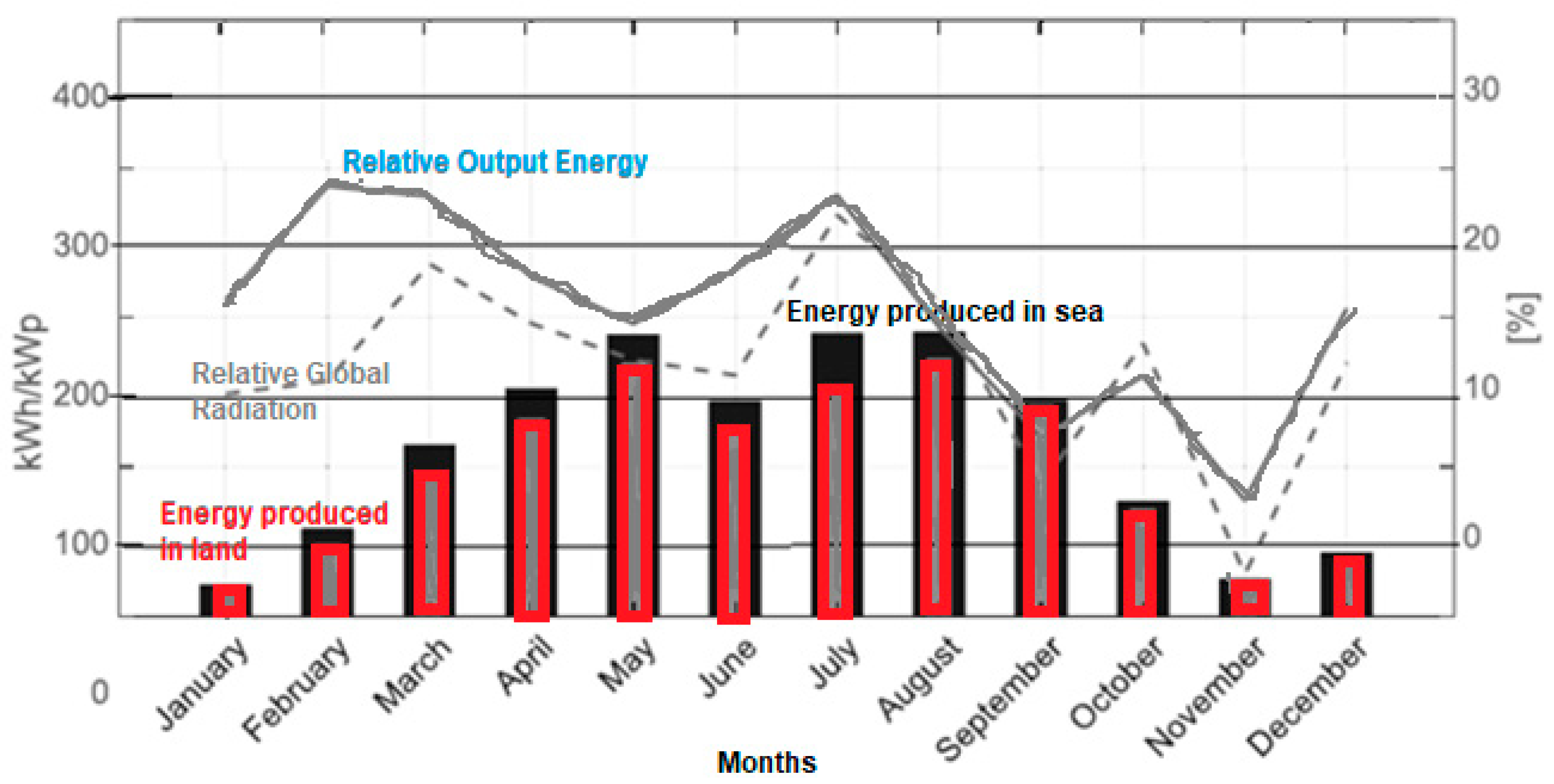
An interesting conclusion for the developed analysis (Figure 9) is that the annual yield for the land system is 4625 kWh (1250 kWh/kWp), which is 13% less than the FPV system, which yields 5225 kWh (1412 kWh/kWp) in this year. This interesting research shows that the energy yield of the two systems differs predominantly as a result of lower temperatures in the FPV, which is seen as a great advantage for the implementation of this solution in the near future in a similar way to what Portugal is doing in dam reservoirs under wind fetch effect on the water surface of reservoirs which can result in a larger wind/generated waves.
2.4. Oscillating Water Column (OWC) and Wells Turbines
The functioning of the oscillating water column (OWC) is somewhat similar to that of a wind turbine, being based on the principle of wave-induced air pressurization. The device is set on top of a closed air chamber, which is placed above the water. The passing waves change the water level within the closed housing, creating a pressure variance within the housing inducing a bidirectional air flow (up and down and vice versa). By placing a turbine on the top of this chamber, air will flow in and out of it with the changing air–water level oscillation.
OWC energy power plants have achieved a more extensive development, with full-scale prototypes built in some countries [20,21,22,23,24,25]. The device is constituted by an air vessel, with a free surface inside, which oscillates by the action of waves. This variation of the water level generates an air flow that drives one or more air turbines coupled to electric generators. The air flow is non-steady, with the flow changing direction twice per wave cycle, and the amplitude of the air flow oscillations changing in different time scales. Therefore, a self-rectifying turbine to respond satisfactorily to these pulse operating conditions is necessary as an integral part of the energy conversion chain in an OWC. The power produced by Wells turbines of different diameters is presented in Figure 10 [21,22,23,24,25].
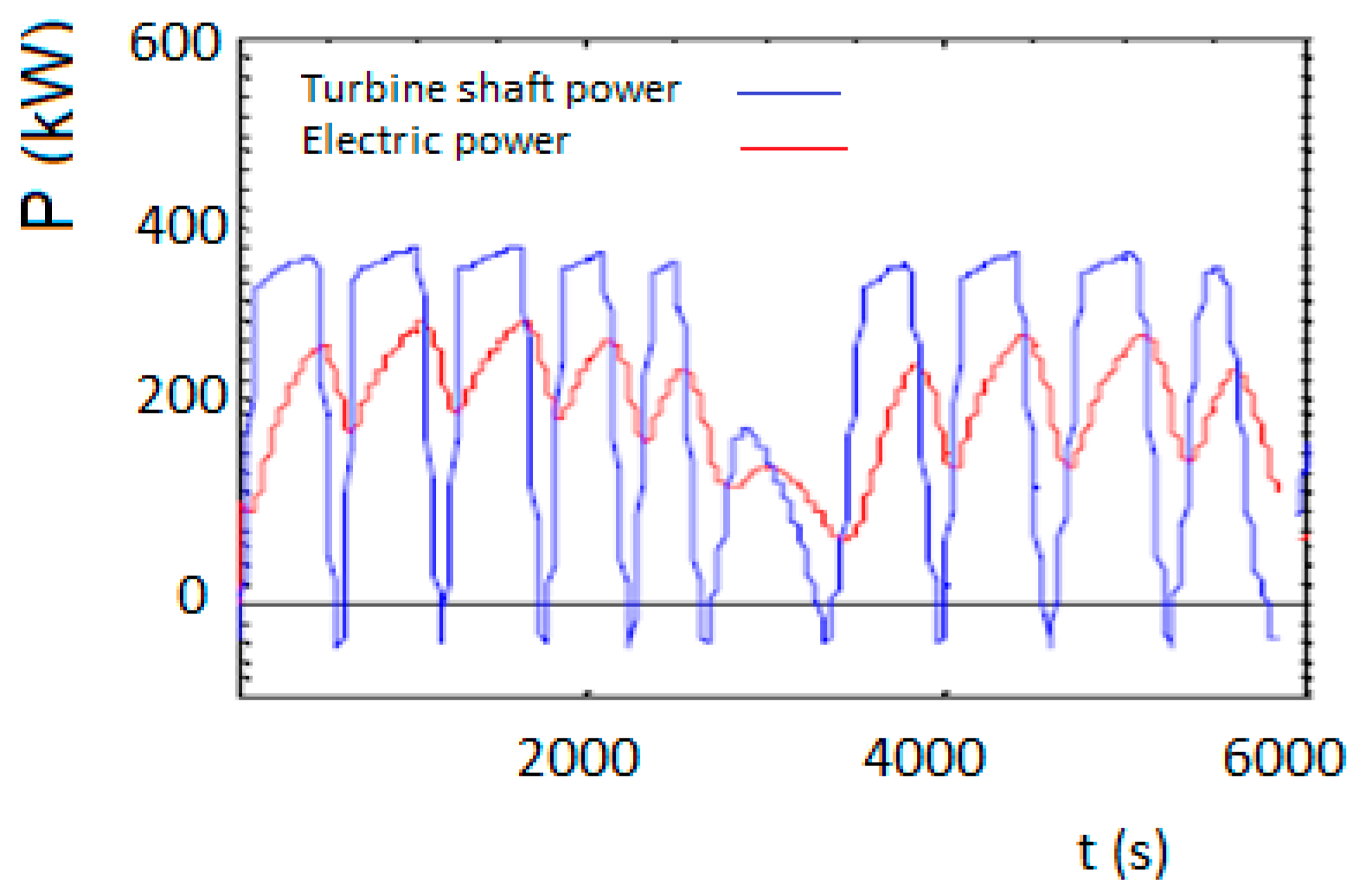
Two options to separate the bi-directional flow can be identified: a Wells turbine to create suction or alternatively, the use of pressure-generating valves [22,23]. Wells turbine blades are designed to always rotate in the same direction regardless of the airflow direction (Figure 11). The efficiency is around 58% (Table 2) [22,23], and the rotational speed does not change by wave cycle or wave effects. Physically, this means the inertia of rotating parts is large enough to prevent significant variations in rotational speed for a given sea state. Experience has shown a significant increase in turbine power output when the plant is equipped with a fast relief valve.
A Wells turbine with a fast relief valve, for a sea state characterized by significant wave height Hs = 2.9 m and energy period Te = 11.2, can avoid aerodynamic stall of the turbine, showing improvements in the power output and a better aerodynamic performance as presented in Figure 11.
2.5. Wind Turbine
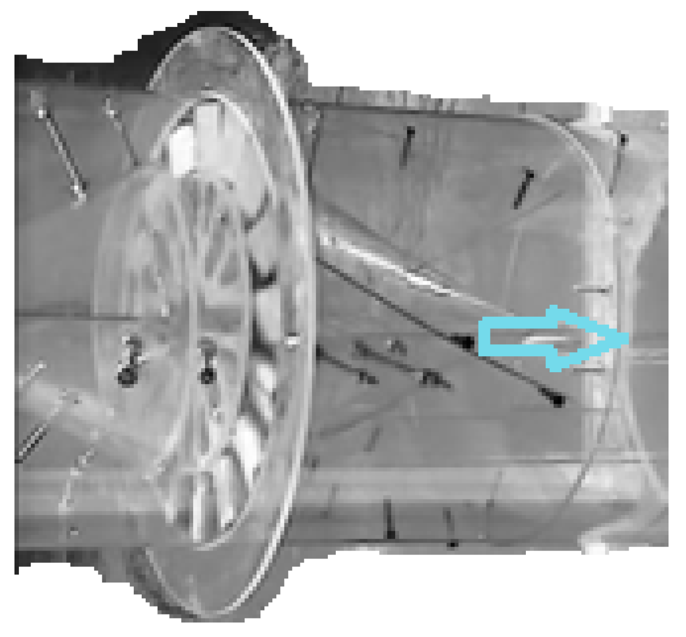
Traditional propeller wind turbines can be replaced by wind farms containing more compact and efficient vertical turbines. Recent research has found that the vertical turbine design is far more efficient than conventional horizontal axis turbines in large-scale wind farms, and when installed in pairs not far away from each other, vertical turbines can increase the farm’s performance by up to 15%. A research team from the School of Engineering, Computing and Mathematics (ECM) at Oxford Brookes [26,27] conducted an in-depth study to show that wind farms can perform more efficiently by substituting the traditional propeller-type horizontal axis wind turbines (HAWTs), by compact vertical axis wind turbines (VAWTs).
Most large-scale wind farms are utilizing HAWTs [26,27]; nonetheless, the turbulent wake effect created by the first row decreases the power output of the turbines behind by up to 40%. Vertical axis wind turbine (VAWT) research [26,27] has shown that this type of turbine exhibits the opposite behavior when implemented in wind farms, and apparently they can enhance each other’s performance (Figure 12 and Figure 13) as a domino effect. Furthermore, maintenance costs are lower due to fewer moving parts, which also makes them easier to install in different scales, and, opposite to HAWTs, they can be installed in sites with varying flow conditions (i.e., varying wind direction, as happens at sea level) [26,27].
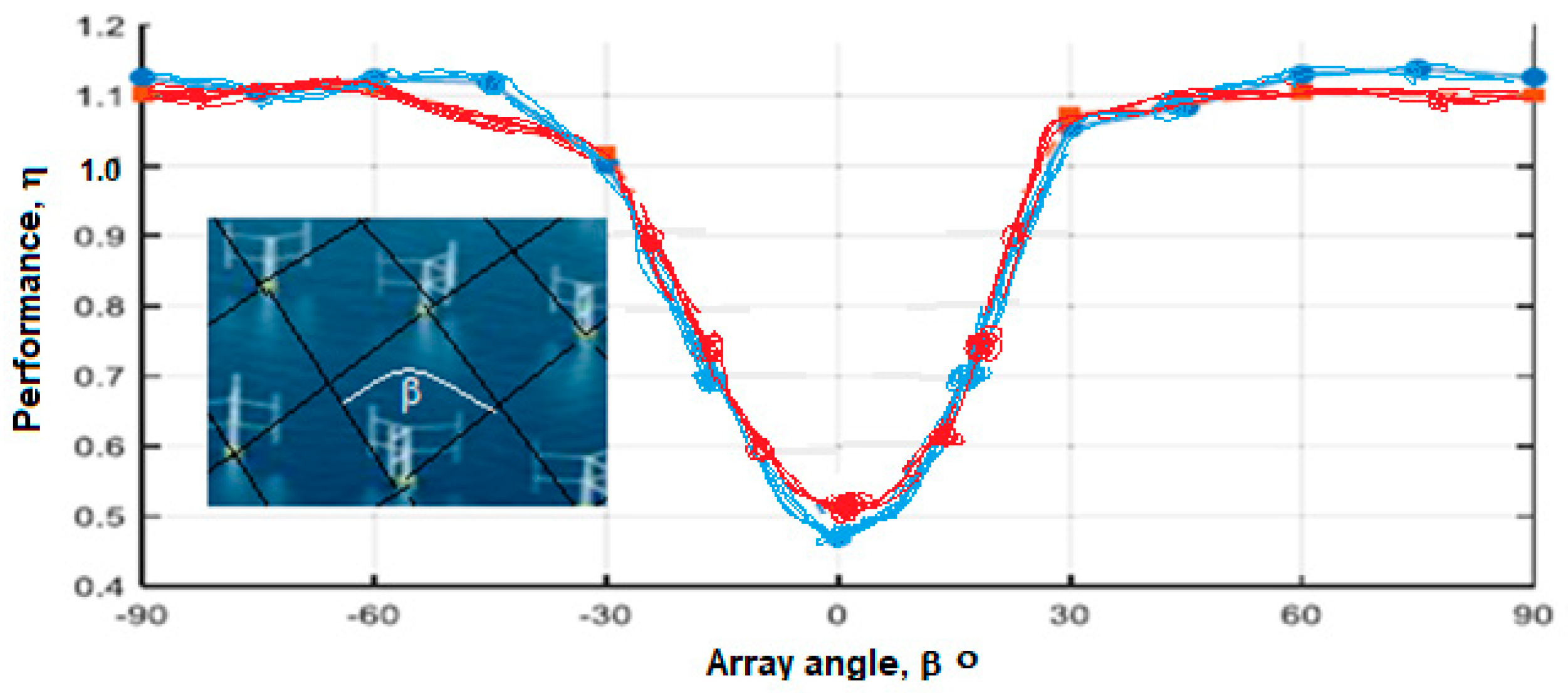
The average performance of two VAWTs in parallel against a varying array angle with a distance between them of 2 diameters is shown in Figure 13.
2.6. Green Hydrogen Production and Storage
Hydrogen is very likely to have a role to play in achieving decarbonization targets worldwide, with investments and innovation scaling up year after year. However, costs remain high and for clean hydrogen to be most effective at integrating high shares of renewable energy, the storage is a vital piece of the energy transition puzzle. The threat of climate change is driving monumental shifts in industry, investment, and regulatory policy, and the transition to green renewable energy is a key part of this. As a response, EDP became one of the first major companies with innovative solutions to contribute to the control of global warming by 2050. The legislation sets an ambitious target to bring all greenhouse gas emissions to net-zero by 2050. This will require a combination of technology breakthroughs and developments in RES, such as wind and solar, which have rapidly increased in the past decade. However, there is still an urgent need to reduce the costs and to achieve higher efficiencies in the renewable energy sector, since clean energy has to completely replace fossil fuels.
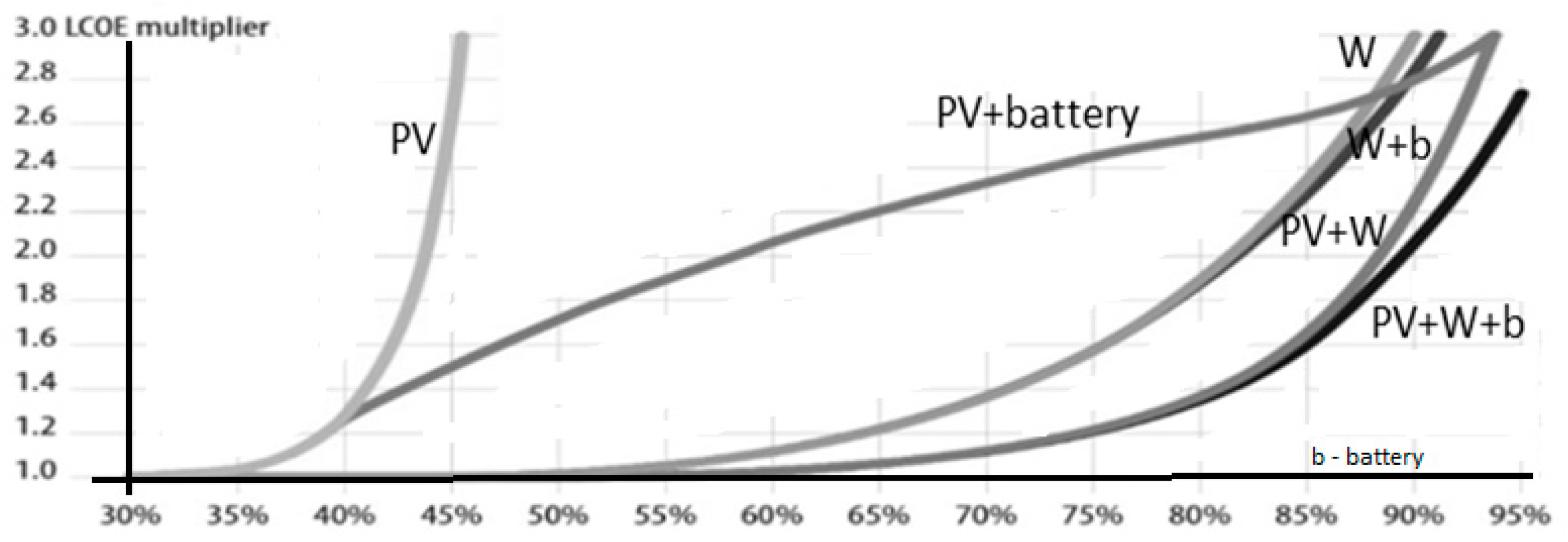
With the inherent intermittency of renewable energy sources, such as wind and solar, there is a pressing need for large-scale storage of clean electricity—wind and solar energy can only be produced when the weather allows it, and often, not in line with consumer demand. The need to store clean energy, coupled with technological breakthroughs in clean hydrogen solutions, have led it to become a promising technology, and global industries are eager to discover how hydrogen could become part of their plans for sustainability. Green hydrogen is made by electrolysis—using electricity from renewable energy sources to split hydrogen molecules from oxygen molecules in water. When used, the hydrogen is re-combined with oxygen to provide electricity and heat. The by-product of this process is water, with essentially no damaging emissions. Levelized costs of electricity for different power supply options are shown in Figure 14, with several advantages for a combined source solution of PV + wind and battery (PV + W + b), attaining 95% for electrolyzer utilization.
Portugal is well positioned in Europe to become a leader in hydrogen production and technology implementation due to its abundant renewable sources onshore and offshore, and in many cases untapped, with modern gas and electricity networks, and in interconnection both with Spain and other EU countries. For this reason, sea water can be used as an “infinite” reservoir to help in source availability. The chapter of green hydrogen is causing a co-location rethink in regions near the sea, on the coast, which have been considered, as desolate and unproductive areas [28].
2.7. Desalination
In some arid regions, the scarcity of freshwater resources and the need for additional water supplies is already critical and will be increasingly important in the near future [29,30]. Desalination requires vast amounts of energy, which in some places is currently provided by fossil fuels. Hybrid energy systems, which combine different energy techniques and sources, appear to offer the most promising solutions in a wide range of water-energy-food scenarios. In regions with emerging water scarcity and high solar radiation, novel hybrid energy-driven systems coupled with highly efficient desalination processes appear to be promising.
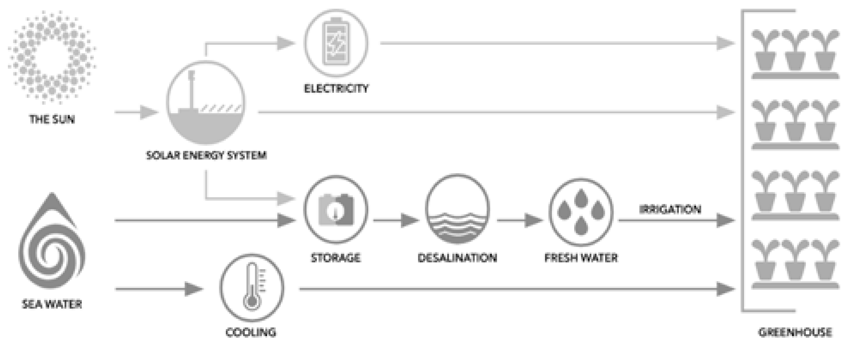
Desalination plants powered by solar or wind energy, in off-grid systems, in many cases equipped with batteries for energy storage, can reduce the complexity of the desalination process. In order to achieve the optimal economic effect, the selection of the appropriate technology will depend on a number of factors, including region location, the characteristic source of raw water, water demand and available water distribution network, the distance from customers, as well as predicted investment outlays and the operating costs [30]. In Figure 15, an example is presented of the process of desalination in combination with solar PV to support irrigation in a water-energy-food nexus.
2.8. Batteries
Due to rapid improvements in lithium technology, modern lithium battery systems quickly superseded traditional lead-acid batteries as manufacturers developed smart, modular systems to suit different energy storage applications. Batteries also play a significant role when it comes to energy storage and are currently more advanced than the electrolyzers used in green hydrogen generation. As a result, batteries may have the edge over hydrogen for use in electric cars and domestic energy use but are not so practical when it comes to aviation, shipping, long-haul transport, and heavy manufacturing. Hence, batteries need to be well-suited to fast frequency control, quick response times, and very high ramping rates, to operate in combination with hydropower, OWC, wind and solar PV turbines, and the storage reservoir’s capacity for an optimum flexibility of operation. Smart battery energy storage systems can store the excess energy generated by different renewable sources to satisfy demand over the 24 h of a day. With an artificial intelligent (AI) multivariable model, a sustainable optimum energy sources management is able to foresee the energy production (i.e., solar PV, OWC, hydro, wind) and to analyze the energy market prices and demand patterns, in order to fit the maximum viability (benefit/cost balance) choice towards the energy independence keeping the enough flexibility and efficiency in the energy networks [9,10,11,12,13,14,15,16,17,18,19,20,21,22,23,24,25,26,27,28,29,30,31].
To avoid over or under sizing, a battery should be selected according to a number of important factors including solar array size (existing or new), system type (on-grid or off-grid), depth of discharge (DoD), environmental conditions, and most importantly, average daily energy consumption (kWh) (see an example in Figure 16). There are some key differences between the various battery types and reasons why certain batteries are better suited to different applications.
2.9. Power Converters
The electronic conversion of energy plays an increasingly important role in electricity-related activities, especially in its use, allowing the control of the energy supply under the conditions required by the most varied loads. At the same time, modern electronic power converters make it possible for most loads to show practically resistive behavior from the point of view of the electrical network. Ideally, an electronic power converter should have unit output, which means switching devices, being able of resisting any voltage and current value, and having the possibility to switch to any frequency [32,33].
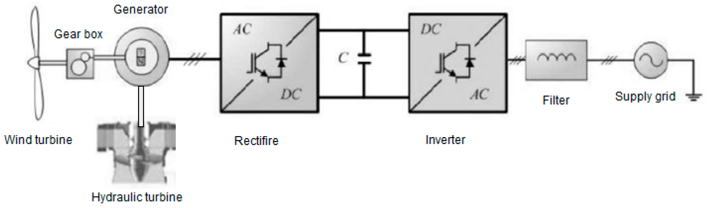
In a hybrid integrated solution, it is crucial to choose the correct power converter topology and system control to optimize the energy output, or to deliver electricity at the adequate level, power factor, and frequency. In Figure 17, a generalized control layout for typical wind and hydro turbines is presented.
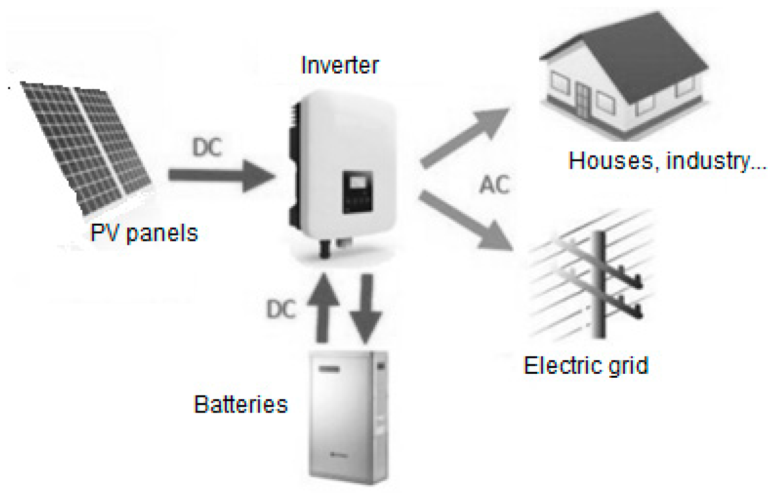
The reversibility of the topological structures of multilevel converters allows them to convert continuously (DC-AC), i.e., in inverter mode, or the alternating-continuous conversion (AC-DC), operating as forced switching switchers. In the latter case, the electrical energy can be stored in a battery to be returned to the mains by the same converter, obtaining an uninterrupted power supply. In addition, appropriate converter control techniques may be applied, operating as a re-actuator, so that the power factor is quasi-unit. Moreover, a hybrid inverter is an intelligent inverter that enables the storage of excess energy in a battery system for self-use. A hybrid inverter operates like a common grid-tie solar inverter but can generally operate in one of several different modes depending on the application, including battery backup mode in the event of a blackout. There are three main types of hybrid inverters: basic hybrid inverter for energy storage, hybrid inverter for energy storage and backup power, and battery energy storage systems (BESS).
2.10. PAT Self-Excited Induction Generator (PAT-SEIG) Model
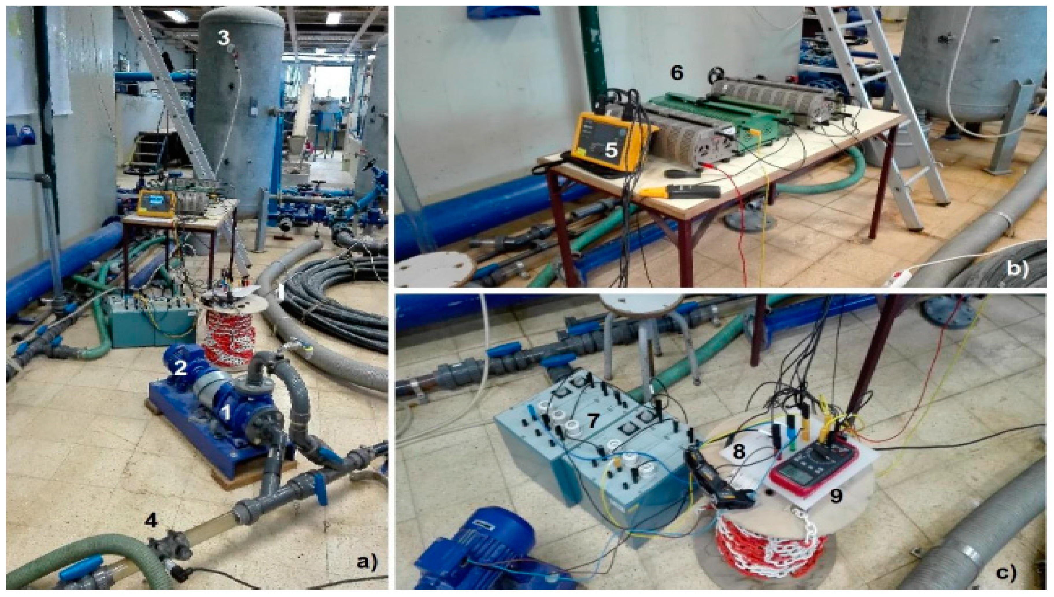
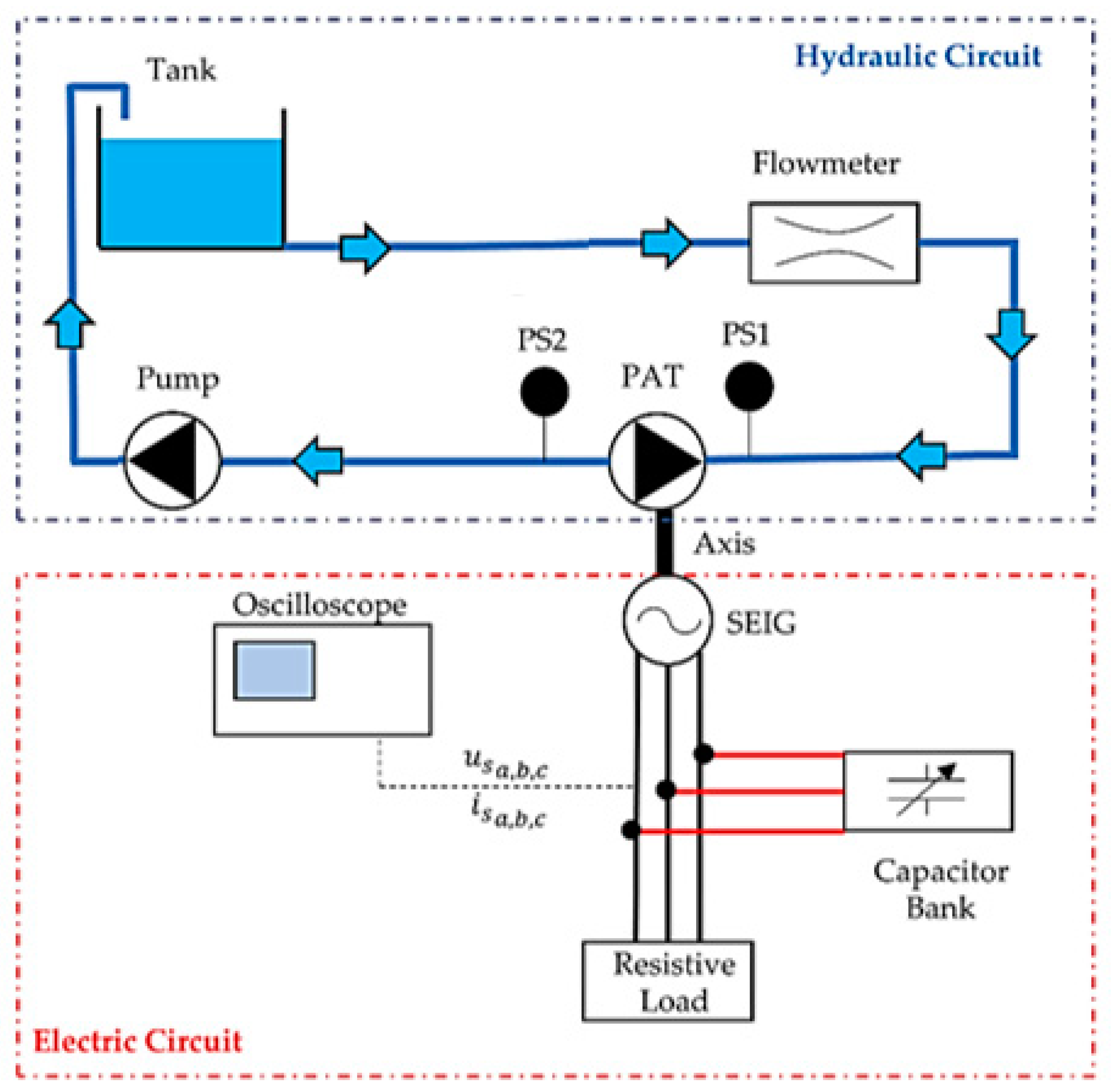
The use of pump as turbine (PAT) was analyzed (Figure 18). To work in off-grid mode, the induction generator of the pump motor requires an external source of reactive power. The reactive power source can be a battery coupled to the machine by an inverter or a set of capacitors connected directly to the machine. The latter solution is called a self-excited induction generator (SEIG). PAT and SEIG can be coupled mechanically by a shaft operating as a PAT + SEIG system (Figure 18). The analysis of this symbiosis is crucial since the global efficiency of the recovery system (PAT + SEIG) depends on hydraulic + mechanical and electrical efficiencies [32].
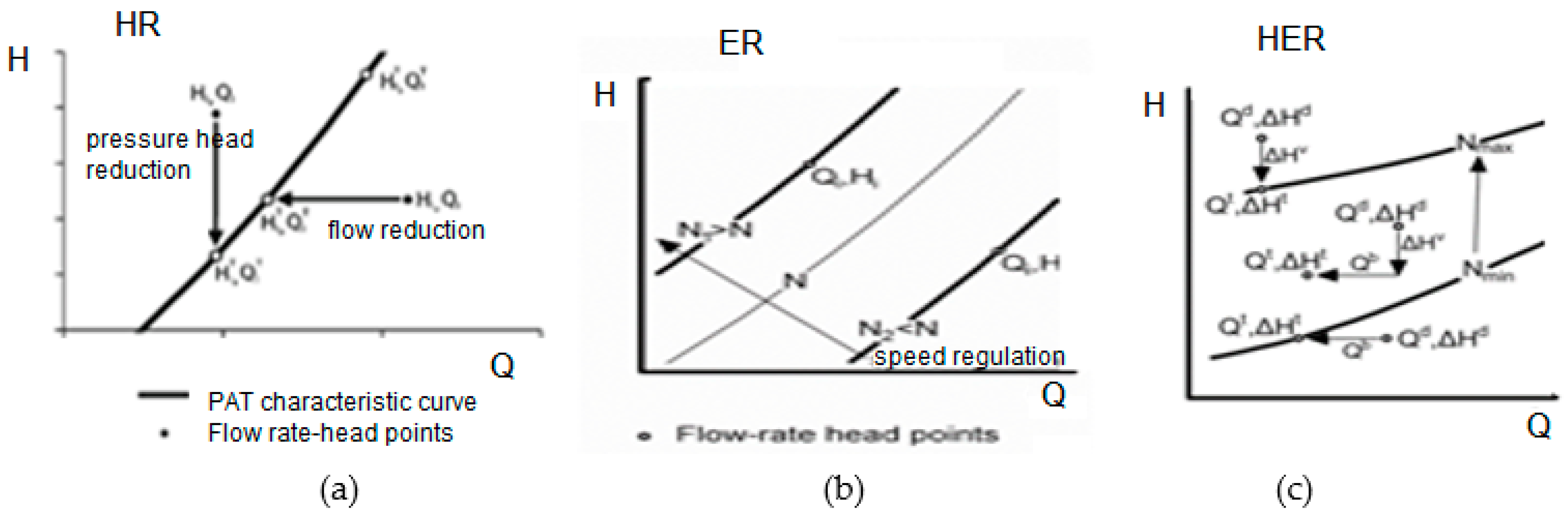
A hydropower plant installation scheme is shown in Figure 18, and its PAT operating conditions, both for hydraulic regulation (HR), electrical regulation (ER), and hydraulic and electric regulation (HER) modes, are shown in Figure 19 [34,35,36,37]. A variable operating strategy (VOS) design procedure for PAT in HR modulation was recently developed. This form of regulation implies an effective energy production lower than the maximum based on both available discharges and heads. Conversely, in ER mode, the operating speed of the generator is modified to match the load conditions determined by the instant flow discharge and head drop values, namely the PAT characteristic curve is modified to match the available head in a combined regulation (HER) [38,39,40]. The installation of a PAT + SEIG solution is presented in Figure 20 and can integrate Hy4REN as a less expensive turbine configuration.
3. Materials and Methods of the Idealized Energy Concept
3.1. Reasons for this Research
The development of the previous section assisted by presenting all the technology upon which the new solution is based, showing its robustness, and supporting it (Hy4REN).
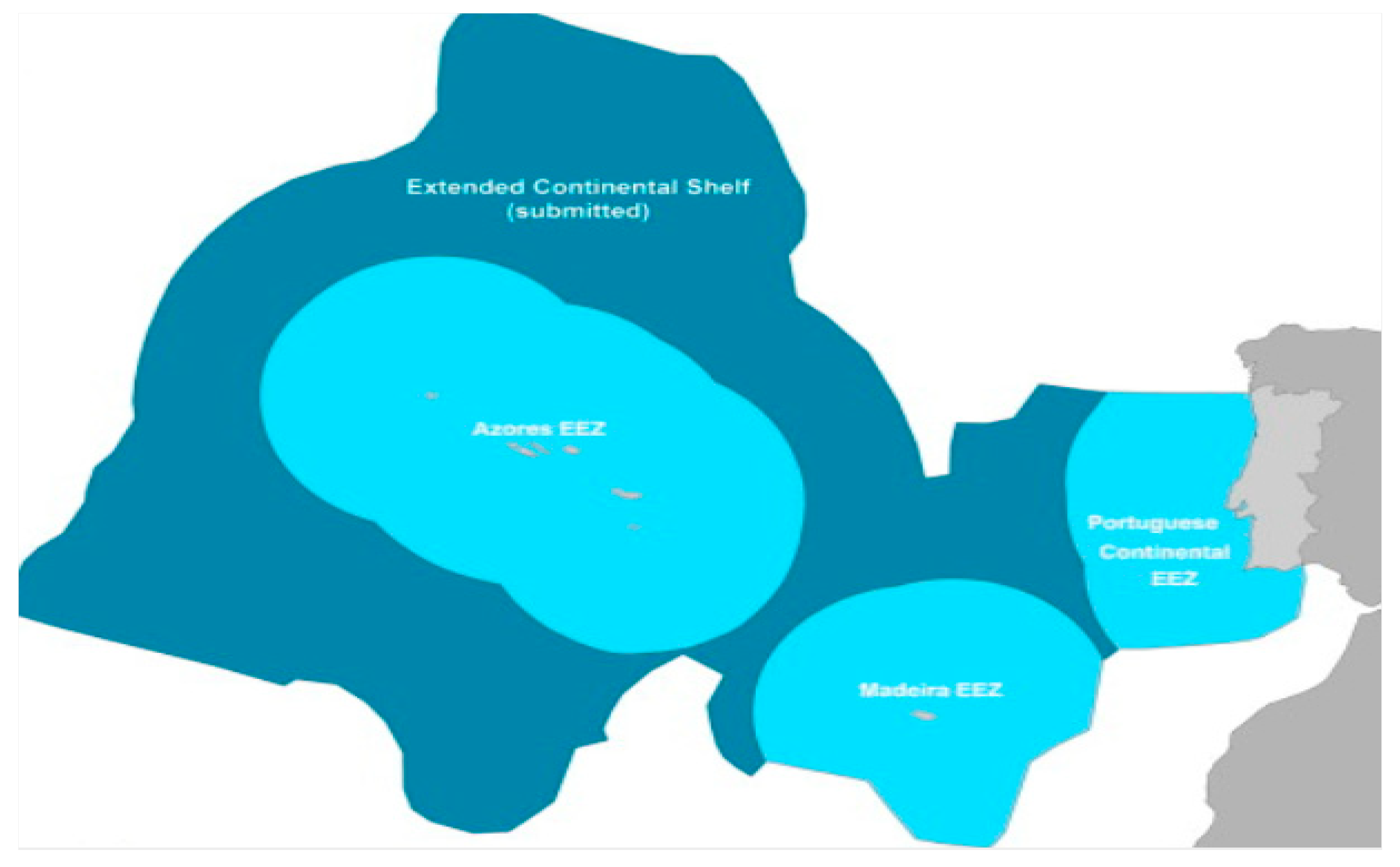
Portugal’s Exclusive Economic Zone (EEZ) is the third largest in the European Union, with an area of 1,727,408 km2, being the 20th largest in the world. However, in its last petition to the UN, its Exclusive Economic Zone extended to cover an additional 2.15 million km2 of the adjacent continental shelf. Thus, the country is poised to hold an EEZ of more than 3,877,408 km2 (see Figure 21). So, the idea of using sea water in a compact renewable energy source combination seems to be a very promising solution that can be applied in offshore, nearshore (with some wave protection), or even in onshore after some adaptations.
The Hy4REN concept will demonstrate the long-term viability of integrated renewable technology for the recovery of energy in offshore or nearshore solutions across Portugal’s sea area EEZ or along its coast, with favorable conditions for its implementation. This solution will allow the reduction of CO2 emissions and the use of available energy sources, such as from the sun (floating PV and land PV), oscillating water columns (OWCs) with Wells air turbines, pumped hydropower energy storage (PHES) with hydram (ram pump), Water-Air Transient Technology for Energy Storage (WATT4ES), and wind, in a complementary and integrated combination to cover these specific objectives: It is economically viable from small capacities (10 kW) to higher power values (2 MW) depending on the size and type of shore application, and it is resilient to the long-term viability challenges presented by climate change, clean mobility challenges, and smart cities development. This improved technology will present several advantages: (a) it will have a short payback period and an ability to adapt, through smart control, to long- and short-term changes; (b) a modeling and decision support system (MDSS) facilitates the optimal design, implementation, and operation of the Hy4REN energy recovery system from available sources into four ways of energy prosumers (producer + consumers) in a hybrid integrated solution that includes four technologies, namely, (i) hydropower + pumped storage, (ii) solar PV, (iii) OWC, (iv) wind/air technologies for renewable energy network (REN); (c) it will enable a faster uptake of Hy4REN energy recovery systems in the market through notifying and influencing the development of supporting social, institutional, economic, and energy governance policies.
The uptake of Hy4REN can be through: (i) best practice organizations’ management models in the water-energy-food nexus; (ii) the positive impact on social factors such as the cost of energy for consumers (i.e., domestic, industrial, general public, and for electric vehicle (EV) mobility) and corporate social responsibility of prosumers; (iii) best practice economic policy addressing energy and carbon cost as well as taxation/incentives; (iv) the promotion/dissemination of the Hy4REN concept and results in order to generate awareness, interest, and action across the entire value chain in Europe and worldwide, with a particular focus on countries with shorelines; (v) the acceleration of the market replication of Hy4REN energy recovery through the definition of the overall value chain, identification of the key players, development of an exploitation plan, and investigation to ensure that the concept of scalable modules is commercially accepted.
3.2. Conceptualization
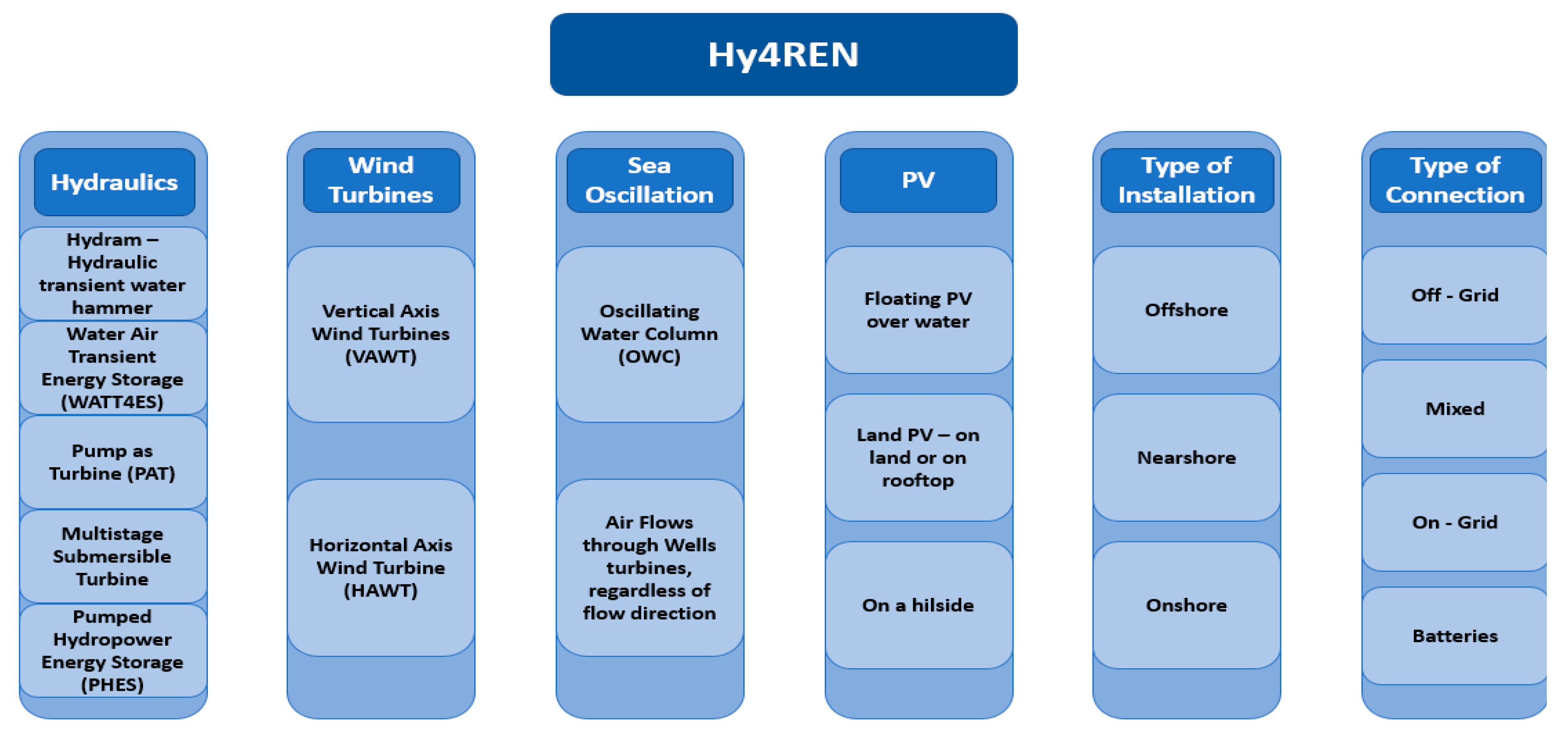
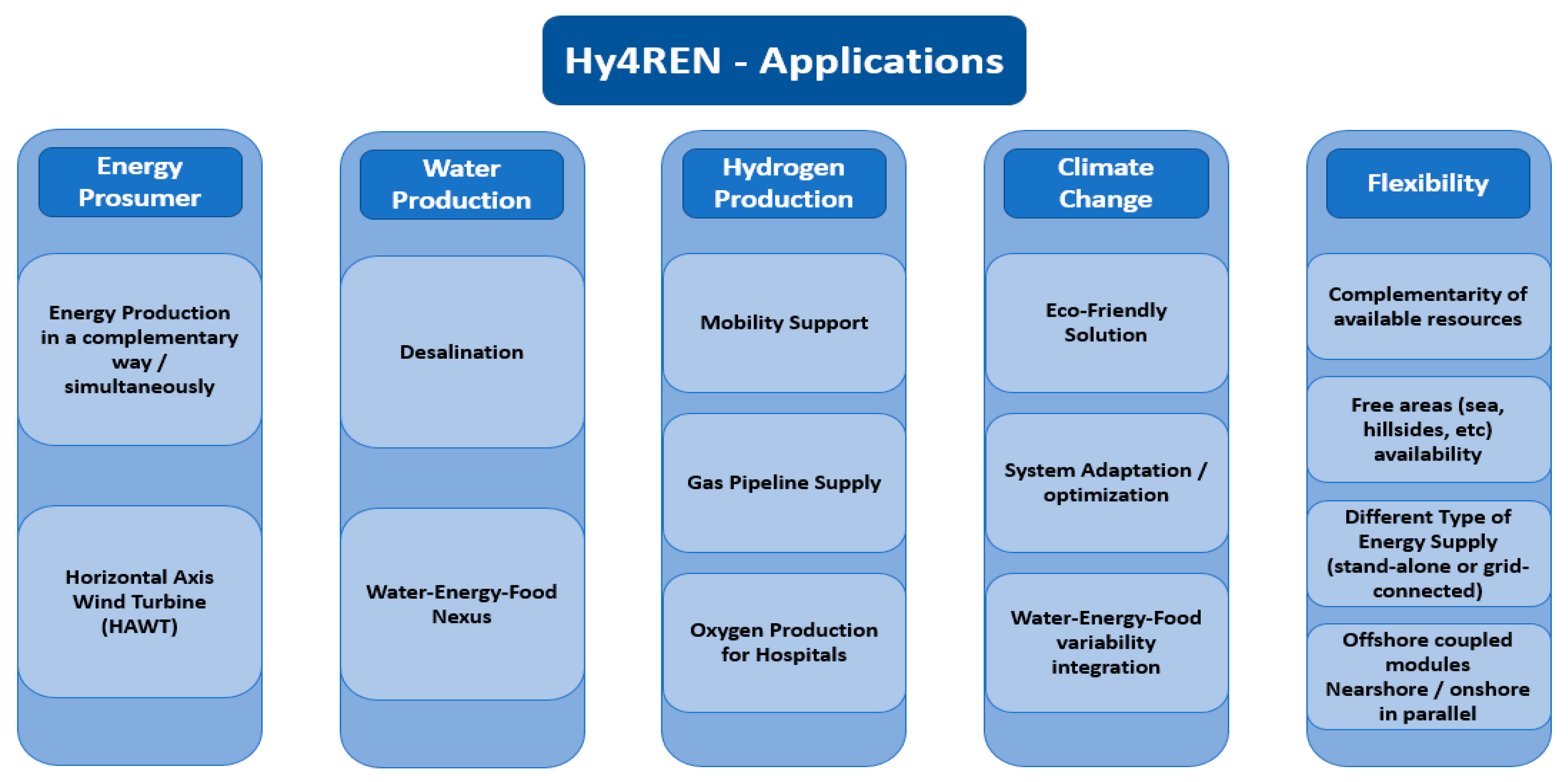
Sea water is a free and renewable “infinite” resource, as well as sun and wind when combined, and using hydropower and pumped storage technology can offer a new hybrid integrated concept of prosumer energy solution. Spending the minimum energy, in a loop process, with the help of a hydram solution based on water hammer-induced conditions, all remaining energy sources are available to support industrial processes (i.e., manufacturers, water industry in different sectors) feeding the electric network, feeding EV mobility, producing hydrogen and desalination, supplying island energy, with on-grid and off-grid solutions, depending on the type and site of installation, in a sustainable and reliable smart-compact solution. This is why a new integrated renewable energy concept called Hy4REN—Hybrid for Renewable Energy Network—is studied. Robust technology, when combined, results in an optimal energy solution that is more reliable and flexible, with several associated benefits in terms of technical, economic, and social impacts. Figure 22 gives the approach for the integration of energy solutions of different levels and interests, such as by the combination of different robust know-how about components and types of installation and connection, showing the huge flexibility of this system, and it also shows the associated applications from energy balance between production and consumption (i.e., prosumer). The Hy4REN concept can contribute to the reduction of climate change effects with a clean, renewable, scalable, and adaptable energy solution, in a flexible source complementarity of operation and location adjustment.
Based on well-known investigation already developed and presented in Section 2, essentially two main configurations can be addressed (with more or less adaptations, when necessary).
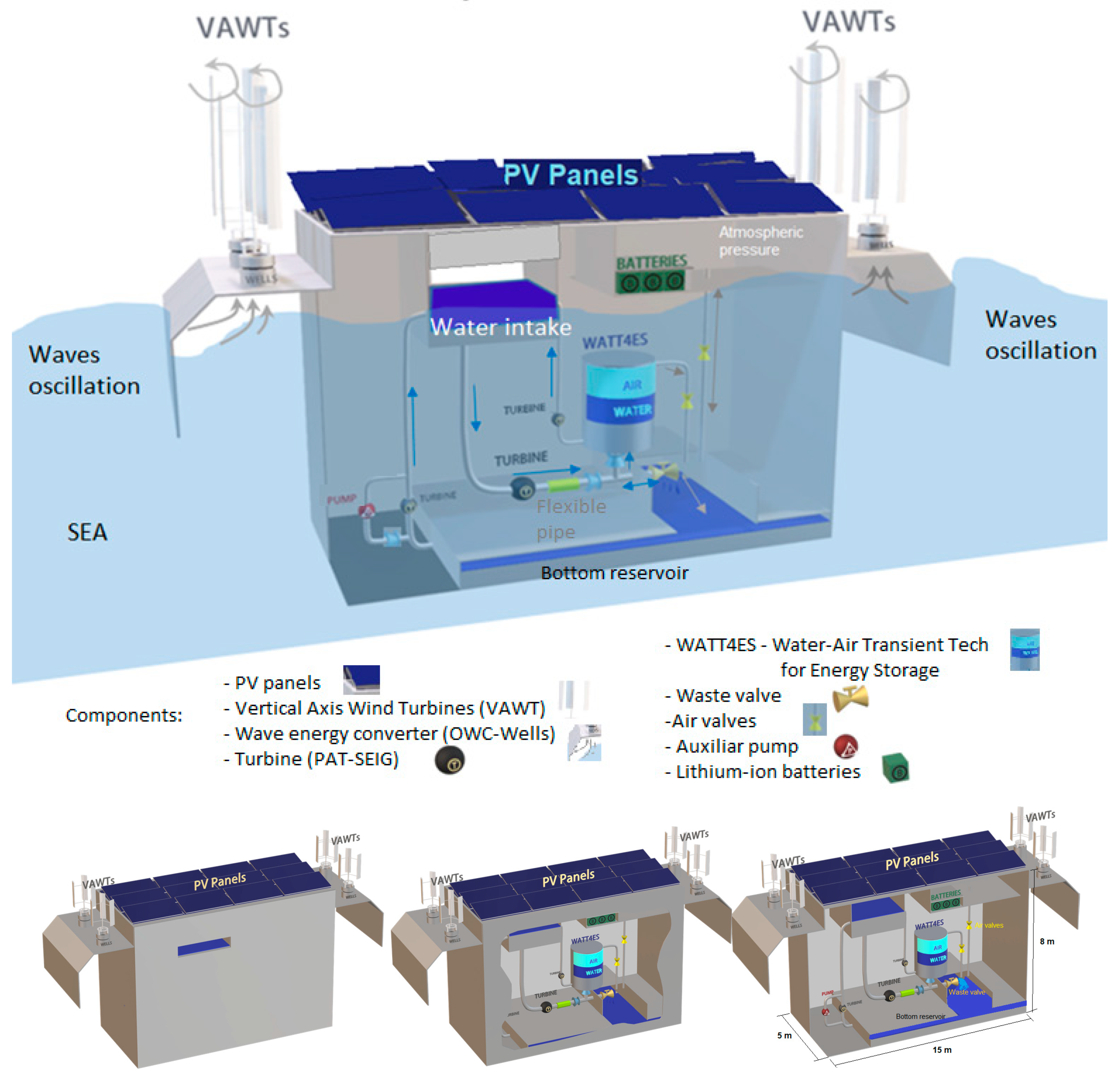
The first configuration is a compact system to operate in offshore conditions (see Figure 23), where all the technologies are presented in a compact module. The technologies can be connected in parallel to each other, as floating solutions not only for PV as shown in Figure 24, but including inside hydropower and pumped storage using a hydram with transients induced by valve maneuvers simulating as a pumping system to be used without spending energy, or using pump as turbines coupled with an induction machine that can operate in turbine or in pump mode, depending on the flow direction and the water levels in the upper and bottom reservoirs. There is a surge vessel, partially filled with water and air, which due to increasing pressure caused by the induced hydraulic transients allows for energy storage (as potential energy in the WATT4ES component). There is also an oscillating water column (OWC) dependent on sea waves, expelling and admitting air in the upper box-wall, which creates an airflow that acts upon Wells turbines, operating regardless of the flow direction, since the turbine blades always rotate in the same direction, constantly feeding a generator. Floating PV panels (FPV) are installed on the top of the module, providing more energy and complementing the Hy4REN solution, as well as vertical axis wind turbines (VAWTs), which present better performance for offshore solutions than horizontal axis wind turbines (HAWTs) when installed in parallel. Batteries/inverters are also inside of this compact module for the self-excited induction system (SEIG) to start the operation of the energy generation in the induction motor/generator of the pump as turbine in turbine mode.
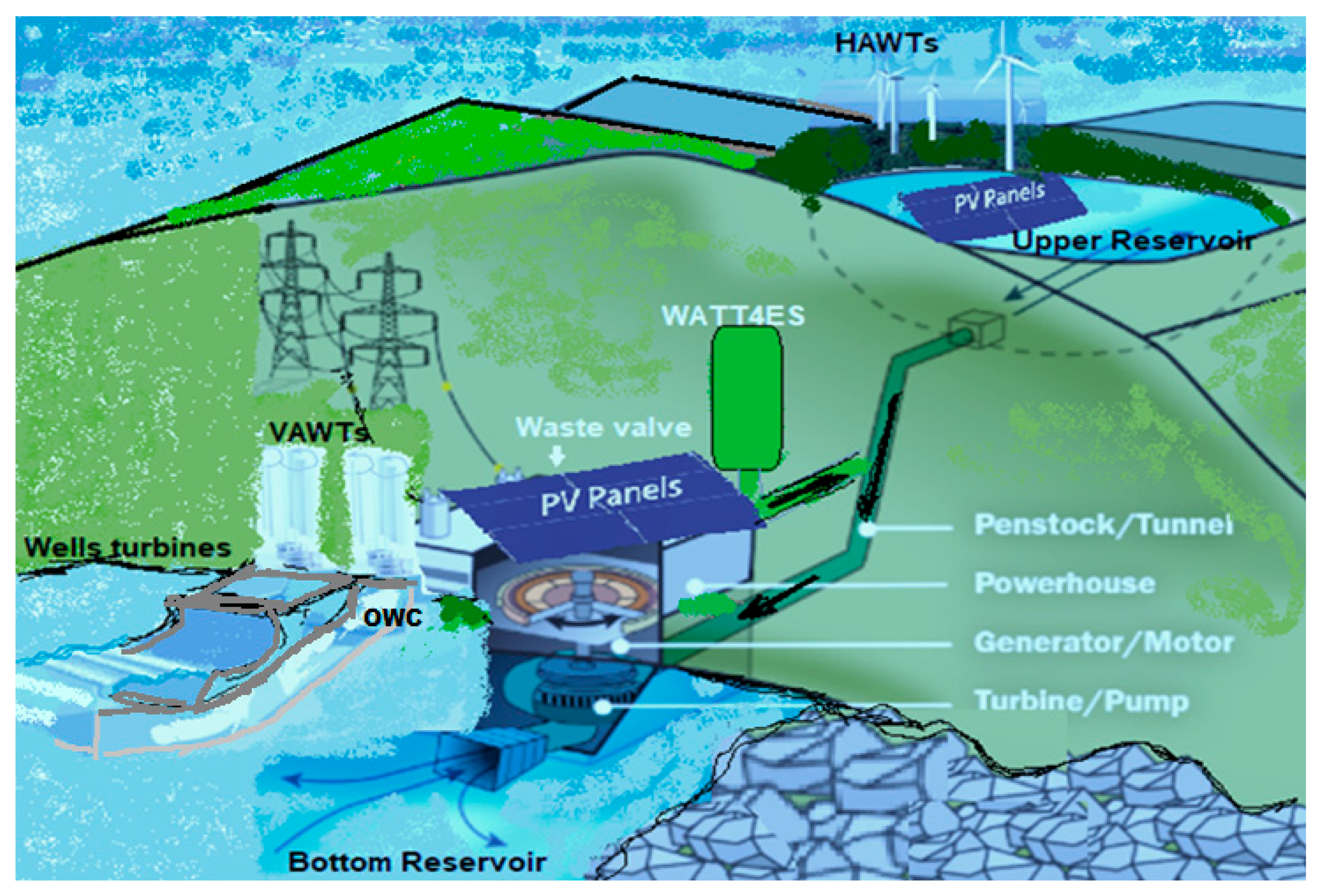
The second configuration is a system extended along the coast slope (Figure 24), from the sea level (with wave protection system when necessary) where an OWC wall system is installed and the water intake for the pump system and the tailrace for the hydropower solution, where the sea water can be pumped and stored on the upper land reservoir (in the top reservoir or in WATT4ES) or turbined from the upper to the sea, where a hydram can also be activated in the hydropower conveyance system connected to the potential energy storage system (WATT4ES) by induced hydraulic transient conditions to pump water without consuming energy in a loop system. Wells turbines are also installed on the top of the OWC structure, making use of the air-flow generated due to sea water level oscillation or waves, where are coupled VAWTs. In this nearshore solution, PV panels can be installed on the rooftop of a small powerhouse where the onshore inverters/batteries/capacitors are, in a safe place away from wave and tidal threats, and FPV in the upper water surface reservoir, increasing the PV efficiency and avoiding lake evaporation.
3.3. Main Components and Type of Operation
3.3.1. Hydro
The water starts by entering the module through an opening on the side top like an open channel, onto an upper reservoir to feed a penstock, keeping a constant flow, accelerating toward a hydro turbine (or a PAT) to produce energy. After leaving the turbine, the water passes through a flexible pipe to absorb pressure variations and excess flow when the check valve downstream closes and then it goes to the waste valve, which in a constant open/close maneuver creates an effect as a ram pump. This mechanism consists in a valve that opens and closes sequentially, generating pressure that forces the water into the WATT4ES. By forcing the water into this reservoir, there will be an increased potential energy storage, which will be used to turbine the water up again to the upper reservoir, generating more hydro energy. By a small pipe connected between the top of WATT4ES (air under pressure) and the top of the bottom reservoir, this pressure is used to remove water from the bottom reservoir enabling once again the production of hydro energy, avoiding the use of the auxiliary emergency pump. Approximately two thirds of the flow that enters the module goes inside the WATT4ES, and the rest passes through the ram pump waste valve onto the bottom reservoir. Once the pressure inside the air vessel is high enough, a relief air-valve is opened and increases the pressure on the lower reservoir. This pressure rise will be used to elevate the water back to the sea level again, re-initiating the water flow cycle. This composes the hydropower cycle with three hydro turbines and one auxiliary pump just in case of any emergency of battery load. All the energy can be transmitted directly by a subsea cable to the land to be consumed locally as a stand-alone system, or sold to the electrical energy network, or stored in Hy4REN batteries to be transmitted to land users later. An AI module is advised to manage and optimize all procedures.
3.3.2. Solar
With the Hy4REN module profile, there is free space on top and so it should be taken advantage of. The use of floating PV panels offshore greatly increases the efficiency of this technology as shown in Section 2, since studies show that the irradiance offshore is far greater than onshore and that, with the cooling effect of the ocean water surface, the efficiency also increases. Part of the energy produced with the PV panels can be used to power the pump (only in case of emergency), and the surplus can be stored in the battery pack or transmitted directly to onshore to be consumed afterwards or injected into the energy network.
The mathematical modeling of PV arrays as a single diode equivalent circuit-based model is used because this model offers a good balance between simplicity and accuracy. The I–V characteristics of the practical PV device, consisting of multiple cells in a parallel-series combination, is given as:
The output power PPV of the PV arrays will depend on the current IMP, short circuit current Isc and voltage VMP, and the inverter efficiency ηinv. The ideality factor a is a value provided by the manufacturers as a ratio of how similar the behavior of the cell is compared to an ideal diode, and VT corresponds to the thermal voltage.
3.3.3. Wind
Vertical axis wind turbines (VAWTs) will also be used. This choice is based on the fact that whilst still producing energy, they are significantly lighter and smaller than horizontal axis wind turbines (HAWTs), allowing their integration on the Hy4REN module and on the other hand reducing the cost of the module and having the advantage to produce more energy, independent of the wind direction. In the same way as solar production, the energy can be consumed nearby transmitted by an electric subsea cable or stored in a storage system such as batteries or flywheels. Another air turbine located below the VAWT is the Wells, installed on the top of the OWC part of this Hy4REN device.
For the study of a wind turbine energy generation model in a hybrid plant or in a wind farm, the bin method and statistical analysis (the Rayleigh distribution) are considered. The following equation calculates the power produced by a wind turbine system:
where ρ is the density of the air (1.2041 kg/m3), AWT is the area swept by the blades, uw is the wind speed, Cp is the power coefficient, and nmech is the mechanical efficiency of the wind turbine rotor.
3.3.4. Wave or Sea Water Surface Oscillation
The wave energy is obtained from the oscillating water column component applied to the wave or water surface oscillation energy converter on the front sides of each module. The orientation and anchorage of these platforms should be favorable to the capture the surface oscillation depending on the dominant winds in each place to be installed. It basically consists of a chamber with venting through a Wells turbine on the top. With the oscillation of the sea surface and with some waves, the free surface will go up and down, and the air induces the Wells turbine to generate energy independently of the flow direction, keeping it in rotation. Making use of a specific turbine whose blades always spin in the same direction as presented in Section 2, regardless of the direction of the airflow, it is possible to obtain a constant energy production all the time and suppling at the same time air to also improve the VAWTs, located on top of the Wells, with an efficient operation.
The power available in the wave is dependent on the group velocity cg at which the wave energy is propagated. The energy flux in the vertical plane is the interest for this study; therefore, the potential power can be expressed as:
where ρ is the water density, g is gravity, Aw is the amplitude of the incident wave, and T is the period of the wave.
3.3.5. Energy Storage System
The Hy4REN can be operated in a stand-alone solution or even directly connected but, dealing with intermittent sources of energy (such as solar and wind), the demand is not always in line with the production of energy. Thus, it is necessary to have a storage solution (WATT4ES in Section 2) for the surplus of non-consumed energy, for when it is needed, making the module self-sustainable and self-reliant on the energy production. It is also possible to associate this module with classic energy storage systems, for example a pumped hydro energy storage system (for a nearshore or onshore solution) or even any type of batteries. WATT4ES stores energy in the form of potential by increasing pressure, allowing us to turbine water again in a cycle procedure. This hydropower can be stored in the batteries existing in Hy4REN or transmitted directly to land users, depending on the distance of each module from the land, or can supply energy to ships.
The water head of a turbine is the difference in water flow energy per unit mass between the inlet and outlet sections of the turbine, in m, as expressed in Equation (7).
where Q is the flow, H is the net hydraulic head, and is the turbine efficiency.
3.4. Expected Impacts
During the research development, another concern appeared, which is related to the global fuel crises induced by wars and climate change, which already have observed effects on the environment of all countries. The magnitude of climate change over the next few decades depends primarily on the amount of greenhouse gases emitted globally, and how sensitive the Earth’s climate is to those emissions. Temperatures will continue to rise, with changes in the precipitation patterns and more droughts and heat waves, hurricanes will become stronger and more intense, sea level will rise, and the Arctic is likely to become defrosting ice. These impacts are already happening and extend well beyond an increase in temperature, affecting ecosystems and communities around the world. Things that the population depends upon and values such as fresh water, energy, transport, wildlife, agriculture, ecosystems, and human health are experiencing the effects of these incidents. Water, energy, and food supply depend on climate and weather conditions, and human health is vulnerable to climate change. Extreme weather events may trigger many health threats, and ecosystems are also affected by climate change.
The new integrated renewable energy concept operating in an optimized way can contribute significantly to the reduction of these damaging effects.
4. Design Evaluation and Business Model
4.1. Innovative Design Configuration of the Coupled System
A perspective combination of modules can be seen in Figure 25, which gives a real idea of this offshore application in a scalable and flexible energy integration mode. Its scalable capability makes it a perfect solution for any new future energy project, since it can accommodate different values of demand, just requiring some more modules to be added in an array.
Thus, once the number of modules in the array increases, the efficiency of the system as a whole and investment costs to build each one decreases whereas the energy produced grows, which, consequently, results in a promising integrated renewable energy solution based on well-known technology and a robust, efficient, sustainable, and flexible design. These modules have cylindrical side floats and link cables to keep them connected and oscillating.
4.2. Pumped Hydropower Storage
The main parameters for the design of the hydropower component are presented in Table 3. The energy is produced by a PAT-SEIG placed in the lower part of the module, and the conservative average turbine power is 9.91 kW for the three hydropower systems ((i) from water intake to WATT4ES, (ii) from WATT4ES to the water intake, and (iii) from the bottom reservoir to the water intake). Afterwards, part of the turbined flow is efficiently pumped/hydropowered back to the upper reservoir tank by WATT4ES operation, also producing energy.
In Table 4, the design specifications of the WATT4ES system are indicated. It can be noticed that the hydram in the waste valve plus the WATT4ES mechanism can increase the overall system efficiency by creating potential energy storage from upsurge events.
The other part from the waste valve flow reaches a lower tank (bottom reservoir), and it is immediately pumped/hydropowered again with a submerged pump to the top reservoir. This pumped hydropower system (PHS) operation is optimized with pressure accumulated in the WATT4ES system generating a flow head in the tank, allowing this water to be turbined, avoiding power consumption with the pump.
However, for emergency situations when the WATT4ES pressurization fails, an auxiliary pump is necessary for emptying the bottom reservoir. For this reason, the pump is located downstream of the lower reservoir, closing the system loop when it is not possible to turbine the pressurized flow at this bottom reservoir controlled by air-valves connected to the WATT4ES element. The characteristics of this auxiliary pump are addressed in Table 5.
This combined hydropower generation and pumping operation generates enough energy, offering a conservative value of 86.8 MWh/year, over the energy consumed in the pumping process just in case of emergency situations.
4.3. Solar PV
Floating solar PV is a complementary renewable energy component, integrated in the Hy4REN device, taking advantage of the available surface of the module and the natural environmental conditions. In this case, 16 × 400 W panels are proposed with an installed capacity of 6.4 kW, as is shown in Table 6. The plant was designed based on the average irradiance in Portugal (Table 6, top). The solar PV component can deliver 11 MWh per year (Table 6, bottom), and it is also connected to the battery energy storage system.
4.4. Wind Turbines
Four 400 W VAWTs are proposed for each Hy4REN module, to increase its versatility, placed on two sides of the module (see Figure 23 and Figure 25). The total energy delivered by wind turbines is 4.7 MWh/year, and the functionality of this wind conversion plant is also supported by the OWC through Wells turbines. The main parameters and characteristics of the wind turbines are presented in Table 7.
4.5. Wave Energy Conversion
Due to the geometry of the HY4REN module and after analyzing the wave behavior, an OWC is integrated into the solution by creating lateral semi-submerged wings. The more realistic scenario was applied for wave energy conversion, obtaining an annual energy production of 38.1 MWh. It is worth underlining that the volume of the air chamber can be increased using part of the space under the FPV panels. The design parameters considered for the OWC including Wells turbine size and output power are addressed in Table 8.
Solar PV and vertical wind turbines are connected to battery modules, helping to solve the intermittence problem in a complementary way. Battery specifications are compiled in Table 9. The final annual energy produced by the integrated modules is around 117.3 MWh per year.
4.6. Business Model
In order to develop a viability analysis, an economic-financial model of this research design project is required. Complete economic indicators, CAPEX and OPEX values, are addressed in Table 10 and Table 11. In Table 10, the estimation of all costs is presented. Project revenues will come from electricity sales. For this, the average electricity price in the EU was considered. Investment cost and positive and negative cash flows are taken into account for calculation. Also, a discount rate of 5% is used (see Table 11).
In summary, the Hy4REN idealization new concept presents a positive NPV, a payback in 7.5 years, and an internal rate of return of 16%. Overall, the results obtained are positive, highlighting the profitability of this project (Table 12).
Another important factor to highlight is the environmental benefit besides the technical solution. Hy4REN allows us to avoid around 120 tonnes of CO2 emissions per year. Therefore, almost 200,000 euros can be saved during the lifecycle of the project.
5. Conclusions
In a changing power system, continuous innovation is needed to keep sustainable hydropower efficient and cost-competitive, including innovative measures for infinite sea water exploitation to improve system flexibility, energy efficiency, environmental performance, and sustainability. Solutions to exploit energy production from the sea in offshore or nearshore installations can generate power, not requiring massive dams to be built, and there are very promising near-future solutions demonstrating a new concept of technology integration aiming to reduce energy footprint impacts.
Hy4REN is an integrated module idealized in this research development, which will contribute a production of 140.6 MWh per year, and when coupled to others, e.g., in a total of 50 modules can produce 7 GWh per year. Each module presents an LCOE of 105.95 €/MW, an NPV of €156,426, and a payback of 7.5 years, which can be significantly reduced (by ~50%) when built on a massive scale.
This solution includes hydraulic energy conversion in the sea as one of the main innovative components, combined with the WATT4ES system for potential energy storage using the power of water hammer events, allowing the overall efficiency to be increased and outstanding energy savings of around 50% to be achieved with the hydropower solution in a loop cycling flow from WATT4ES and the bottom reservoir.
Several benefits of this new hybrid solution are evident throughout this research due to the combination of different available renewable energy sources in a module. These sources can be coupled together to increase the energy production and the flexibility, arriving to consumers in an easy way, or alternatively creating potential energy to be stored to feed a pumped-hydropower system, or to charge batteries. The main variables that can be addressed with Hy4REN for the near future are: the complementarity of available renewable resources in an integrated way; the flexibility regarding support for future energy requirements such as social effects (e.g., EV mobility, hydrogen demand, and water scarcity); electricity distribution, and water-energy systems efficiency; and industrial processes within the energy-water-food nexus.
From the simplicity in design and construction of each component for each module, to the intricate connection between all of them, Hy4REN is able to solve a multitude of issues related to renewable energy networks. With the combination of several RES, this module is able to meet customers’ demand while being self-reliant and independent from the power grid. Its scalable capability makes it the perfect solution for any energy improvements, since it can accommodate demands, simply requiring more modules. Thus, once the number of modules in the array increases, the investment required to build each one decreases whereas the energy produced grows, which consequently results in a significant reduction of the payback. Therefore, the main advantages of Hy4REN can be identified as follows: (i) it is profitable, (ii) it requires low capital expenditure and operational expenses (CAPEX and OPEX), (iii) it can produce reliable and renewable energy, (iv) it has flexible adaptation in offshore, nearshore, and onshore locations and can be stand-alone or with grid connection depending on the configuration adopted, (v) it has a modular construction, with each module being independent in production but capable of being linked to others for energy transmission by electric cables, (vi) the modules can be scalable with different sizes, depending on the in-situ implementation, and finally (vii) its integrative innovation based on the complementarity and optimization of resources shows its promising potential.
Regarding future studies, we can expect the following: (i) Additional analyses of the energy system could be carried out for a specific location, facing maritime agitation, wind fluctuations, and a changing share of energy technologies and energy storage system size and capacity. According to the location, it will be essential to observe how the type of integration and the response on sunny or windy days can contribute together for the WATT4ES component. (ii) Therefore, the energy storage characteristics should be modified depending on local conditions of prosumers. (iii) Another interesting challenge is the application of optimization models and AI sensors to improve the energy delivery and to match renewable generation. (iv) A prototype, even in a small-scale pilot, is necessary to analyze the buoyancy support system in each module and the fluid–structure interaction in the most severe sea oscillation conditions. (v) Another challenge is the behavior of the flexible pipe after the downflow turbine from the top reservoir to absorb the water hammer effects induced in the waste valve downstream, allowing an almost continuous turbine flow, powering the hydram in WATT4ES surge vessel. (vi) Finally, all components have been tested either separately or combined, but it will be necessary to monitor the behavior of the module under real conditions.
Author Contributions
Conceptualization, H.M.R.; methodology, H.M.R., B.V. and J.R.S.; drawings, B.V. and H.M.R.; software and calculus, B.V. and H.M.R.; writing—original draft preparation, H.M.R. and B.V.; review and editing, B.V. and J.R.S.; supervision and final preparation, H.M.R. All authors have read and agreed to the published version of the manuscript.
Funding
This research received no external funding.
Institutional Review Board Statement
Not applicable.
Informed Consent Statement
Not applicable.
Data Availability Statement
Not applicable.
Conflicts of Interest
The authors declare no conflict of interest.
References
- IHA. The World’s Water Battery: Pumped Hydropower Storage and the Clean Energy Transition; International Hydropower Association, IHA Working Paper: London, UK, 2018. [Google Scholar]
- IHA. Pumped Storage Hydropower Has ‘Crucial Role’ in Europe’s Energy Strategy; International Hydropower Association, IHA Working Paper: London, UK, 2020. [Google Scholar]
- Bhandari, B.; Poudel, S.R.; Lee, K.-T.; Ahn, S.-H. Mathematical modeling of hybrid renewable energy system: A review on small hydro-solar-wind power generation. Int. J. Precis. Eng. Manuf. Technol. 2014, 1, 157–173. [Google Scholar] [CrossRef]
- Available online: https://pplware.sapo.pt/informacao/marrocos-vai-instalar-um-dos-cabos-submarinos-mais-longos-do-mundo-para-enviar-eletricidade/ (accessed on 25 April 2022).
- Hong, C.-M.; Ou, T.-C.; Lu, K.-H. Development of intelligent MPPT (maximum power point tracking) control for a grid-connected hybrid power generation system. Energy 2013, 50, 270–279. [Google Scholar] [CrossRef]
- Kapsali, M.; Kaldellis, J. Combining hydro and variable wind power generation by means of pumped-storage under economically viable terms. Appl. Energy 2010, 87, 3475–3485. [Google Scholar] [CrossRef]
- Xu, B.; Chen, D.; Venkateshkumar, M.; Xiao, Y.; Yue, Y.; Xing, Y.; Li, P. Modeling a Pumped Storage Hydropower Integrated to a Hybrid pEnergy Storage News. Available online: https://www.energy-storage.news/blogs/storage-will-be-vital-for-hydrogen-to-help-solve-renewable-energys-big-chal (accessed on 9 February 2022).
- Energy Storage News. Available online: https://event.webinarjam.com/register/264/4qqkks6y (accessed on 3 November 2021).
- Simão, M.; Ramos, H.M. Hybrid pumped hydro storage energy solutions towards wind and PV integration: Improvement on flexibility, reliability and energy costs. Water 2020, 12, 2457. [Google Scholar] [CrossRef]
- Besharat, M.; Dadfar, A.; Viseu, M.; Brunone, B.; Ramos, H.M. Transient-flow induced compressed air energy storage (TI-CAES) system towards new energy concept. Water 2020, 12, 601. [Google Scholar] [CrossRef] [Green Version]
- Fatahi-Alkouhi, R.; Lashkar-Ara, B.; Keramat, A. On the measurement of ram-pump power by changing in water hammer pressure wave energy. Ain Shams Eng. J. 2019, 10, 681–693. [Google Scholar] [CrossRef]
- Ma, T.; Yang, H.; Lu, L.; Peng, J. Technical feasibility study on a standalone hybrid solar-wind system with pumped hydro storage for a remote island in Hong Kong. Renew. Energy 2014, 69, 7–15. [Google Scholar] [CrossRef]
- Bajpai, P.; Dash, V. Hybrid renewable energy systems for power generation in stand-alone applications: A review. Renew. Sustain. Energy Rev. 2012, 16, 2926–2939. [Google Scholar] [CrossRef]
- Golroodbari, S.Z.; Van Sark, W. Simulation of performance differences between offshore and land-based photovoltaic systems. Prog. Photovolt. Res. Appl. 2020, 28, 873–886. [Google Scholar] [CrossRef]
- Breyer, C.; Bogdanov, D.; Aghahosseini, A.; Gulagi, A.; Child, M.; Oyewo, A.S.; Farfan, J.; Sadovskaia, K.; Vainikka, P. Solar photovoltaics demand for the global energy transition in the power sector. Prog. Photovolt. Res. Appl. 2017, 26, 505–523. [Google Scholar] [CrossRef]
- Jager-Waldau, A. Snapshot of Photovoltaics—February 2019. Available online: https://0-www-mdpi-com.brum.beds.ac.uk/1996-1073/12/5/769 (accessed on 17 November 2021).
- Haysom, J.E.; Jafarieh, O.; Anis, H.; Hinzer, K.; Wright, D. Learning curveanalysis of concentrated photovoltaic systems. Prog. Photovolt. Res. Appl. 2014, 23, 1678–1686. [Google Scholar] [CrossRef]
- Cazzaniga, R.; Cicu, M.; Rosa-Clot, M.; Tina, G.M.; Ventura, C. Floating photovoltaic plants: Performance analysis and design solutions. Renew. Sustain. Energy Rev. 2018, 81, 1730–1741. [Google Scholar] [CrossRef]
- Pringle, A.M.; Handler, R.; Pearce, J. Aquavoltaics: Synergies for dual use of water area for solar photovoltaic electricity generation and aquaculture. Renew. Sustain. Energy Rev. 2017, 80, 572–584. [Google Scholar] [CrossRef] [Green Version]
- OWC Pico Power Plant Website. Available online: http://www.pico-owc.net/ (accessed on 8 October 2014).
- Corvelo, E. Analysis and Performance Comparison of an OWC Wave Power Plant Equipped with Wells and Impulse Turbines. Master’s Thesis, Instituto Superior Técnico, Lisboa, Portugal, 2009. Available online: https://fenix.tecnico.ulisboa.pt/downloadFile/395142732839/dissertacao%20eugenio%20corvelo.pdf (accessed on 17 November 2021).
- Sarmento, A.; Melo, A.B.; Pontes, M.T. The Influence of the wave climate on the design and annual production of electricity by OWC wave power plants. In Proceedings of the 20th International Conference on Offshore Mechanics and Arctic Engineering, Rio de Janeiro, Brazil, 3–8 June 2001. [Google Scholar]
- Mendes, A.C. Preliminary Design of a Power Take-Off System for the Breakwater-Integrated Oscillating Water Column at Leixões Harbour. Master’s Thesis, Instituto Superior Técnico, Lisboa, Portugal, 2019. [Google Scholar]
- Hansen, J.T.; Mahak, M.; Tzanakis, I. Numerical modelling and optimization of vertical axis wind turbine pairs: A scale up approach. Renew. Energy 2021, 171, 1371–1381. [Google Scholar] [CrossRef]
- Henriques, J.; Lopes, M.; Gomes, R.; Gato, L.; Falcão, A. On the annual wave energy absorption by two-body heaving WECs with latching control. Renew. Energy 2012, 45, 31–40. [Google Scholar] [CrossRef]
- SciTechDaily. Available online: https://scitechdaily.com/more-compact-and-efficient-vertical-turbines-could-be-the-future-for-wind-farms/ (accessed on 8 October 2021).
- Bianchini, A.; Balduzzi, F.; Bachant, P.; Ferrara, G.; Ferrari, L. Effectiveness of two-dimensional CFD simulations for Darrieus VAWTs: A combined numerical and experimental assessment. Energy Convers. Manag. 2017, 136, 318–328. [Google Scholar] [CrossRef]
- PV Magazine. Available online: https://www.pv-magazine.com/2021/05/29/the-weekend-read-age-of-green-hydrogen-causes-co-location-rethink/ (accessed on 10 October 2021).
- Robbins, J. As Water Scarcity Increases, Desalination Plants Are on the Rise, Yale Environment 360. Available online: https://e360.yale.edu/features/as-water-scarcity-increases-desalination-plants-are-on-the-rise (accessed on 25 June 2021).
- Bundschuh, J.; Kaczmarczyk, M.; Ghaffour, N.; Tomaszewska, B. State-of-the-art of renewable energy sources used in water desalination: Present and future prospects. Desalination 2021, 508, 115035. [Google Scholar] [CrossRef]
- EcoSaviour Engineers. Available online: https://www.indiamart.com/proddetail/hybrid-solar-pv-power-plant-with-battery-backup-19669763973.html (accessed on 10 April 2022).
- Fernandes, J.F.; Pérez-Sánchez, M.; da Silva, F.F.; López-Jiménez, P.A.; Ramos, H.M.; Branco, P.C. Optimal energy efficiency of isolated PAT systems by SEIG excitation tuning. Energy Convers. Manag. 2019, 183, 391–405. [Google Scholar] [CrossRef]
- Ramos, H.M.; Dadfar, A.; Besharat, M.; Adeyeye, K. Inline pumped storage hydropower towards smart and flexible energy recovery in water networks. Water 2020, 12, 2224. [Google Scholar] [CrossRef]
- Carravetta, A.; Del Giudice, G.; Fecarotta, O.; Ramos, H.M. Pump as turbine (PAT) design in water distribution network by system effectiveness. Water 2013, 5, 1211–1225. [Google Scholar] [CrossRef] [Green Version]
- Pérez-Sánchez, M.; López-Jiménez, P.A.; Ramos, H.M. Modified affinity laws in hydraulic machines towards the best efficiency line. Water Resour. Manag. 2017, 32, 829–844. [Google Scholar] [CrossRef] [Green Version]
- Fecarotta, O.; Ramos, H.M.; Derakhshan, S.; Del Giudice, G.; Carravetta, A. Fine tuning a PAT hydropower plant in a water supply network to improve system effectiveness. J. Water Resour. Plan. Manag. 2018, 144, 04018038. [Google Scholar] [CrossRef]
- Carravetta, A.; Houreh, S.D.; Ramos, H.M. Pumps as Turbines; Springer Tracts in Mechanical Engineering; Springer: Cham, Switzerland, 2018. [Google Scholar] [CrossRef]
- Pugliese, F.; De Paola, F.; Fontana, N.; Giugni, M.; Marini, G. Experimental characterization of two Pumps As Turbines for hydropower generation. Renew. Energy 2016, 99, 180–187. [Google Scholar] [CrossRef]
- McNabola, A.; Coughlan, P.; Corcoran, L.; Power, C.; Williams, A.P.; Harris, I.; Gallagher, J.; Styles, D. Energy recovery in the water industry using micro-hydropower: An opportunity to improve sustainability. Water Policy 2014, 16, 168–183. [Google Scholar] [CrossRef]
- Pérez-Sánchez, M.; Fernandes, J.; Branco, P.; López-Jiménez, P.; Ramos, H. PATs behavior in pressurized irrigation hydrants towards sustainability. Water 2021, 13, 1359. [Google Scholar] [CrossRef]
Figure 1.
PHES hybrid solution with hydrogen production and desalination.

Figure 2.
Example of an optimization algorithm between available renewable sources (for wind and solar energy).
Figure 2.
Example of an optimization algorithm between available renewable sources (for wind and solar energy).

Figure 3.
Energy contribution of each renewable source to satisfy the demand for different installed powers: power variation (top); satisfaction percentage for different power solutions (bottom).
Figure 3.
Energy contribution of each renewable source to satisfy the demand for different installed powers: power variation (top); satisfaction percentage for different power solutions (bottom).


Figure 4.
Hydram scheme.

Figure 5.
Experimental apparatus at IST Hydraulic Laboratory, as part of the Water-Air Transient Technology for Energy Storage (WATT4ES) system for hydropower and free of charge pumping solutions.
Figure 5.
Experimental apparatus at IST Hydraulic Laboratory, as part of the Water-Air Transient Technology for Energy Storage (WATT4ES) system for hydropower and free of charge pumping solutions.

Figure 6.
Experiments on energy storage: average pressure for air-volume of 67% in the WATT4ES and for increasing Reynolds number.
Figure 6.
Experiments on energy storage: average pressure for air-volume of 67% in the WATT4ES and for increasing Reynolds number.

Figure 7.
Example of a floating PV (FPV) module.

Figure 8.
PV performance as a function of the temperature (left); air temperature variation for an average year (right).
Figure 8.
PV performance as a function of the temperature (left); air temperature variation for an average year (right).

Figure 9.
Comparison of the normalized energy yield from FPV and a land system.

Figure 10.
Average Wells turbine shaft power vs. optimum rotational speed (D in m).

Figure 11.
Instantaneous turbine shaft power and electric power for a Wells turbine for Hs = 2.9 m and D = 2 m.
Figure 11.
Instantaneous turbine shaft power and electric power for a Wells turbine for Hs = 2.9 m and D = 2 m.


Figure 12.
VAWT offshore wind farm.

Figure 13.
Average performance of two turbines in a pair against array angle β.

Figure 14.
Levelized cost of electricity and electrolyzer utilization for different power supply options: PV; PV + battery; wind; wind + battery; PV + wind; PV + wind + battery.
Figure 14.
Levelized cost of electricity and electrolyzer utilization for different power supply options: PV; PV + battery; wind; wind + battery; PV + wind; PV + wind + battery.

Figure 15.
Desalination powered by solar PV for irrigation.

Figure 16.
Battery connected to a hybrid inverter scheme.

Figure 17.
Wind/Hydraulic turbine coupled to permanent magnet synchronous generator.

Figure 18.
Installation assembled at the Hydraulic Laboratory at IST: (a) 1—PAT, 2—induction generator, 3—compressed air reservoir, 4—pressure sensors; (b) 5—digital multimeter FLUKE, 6—three-phase wye resistive load; (c) 7—bank of capacitors, 8—switch, 9—voltmeter.
Figure 18.
Installation assembled at the Hydraulic Laboratory at IST: (a) 1—PAT, 2—induction generator, 3—compressed air reservoir, 4—pressure sensors; (b) 5—digital multimeter FLUKE, 6—three-phase wye resistive load; (c) 7—bank of capacitors, 8—switch, 9—voltmeter.

Figure 19.
Hydraulic regulation (HR) and the effects of the regulation system (a); electric regulation (ER) and the corresponding characteristic curve changes (b); hydraulic and electric regulation (HER) (c).
Figure 19.
Hydraulic regulation (HR) and the effects of the regulation system (a); electric regulation (ER) and the corresponding characteristic curve changes (b); hydraulic and electric regulation (HER) (c).

Figure 20.
PAT + SEIG scheme with hydraulic and electrical circuits coupled.

Figure 21.
Portugal’s Exclusive Economic Zone (EEZ).

Figure 22.
New integrated renewable energy concept—Hybrid for Renewable Energy Network (Hy4REN)—needs (top) and applications (bottom).
Figure 22.
New integrated renewable energy concept—Hybrid for Renewable Energy Network (Hy4REN)—needs (top) and applications (bottom).


Figure 23.
New concept of integrated energy solution module: innovative Hy4REN offshore solution (top), module visualization from outside to inside (bottom).
Figure 23.
New concept of integrated energy solution module: innovative Hy4REN offshore solution (top), module visualization from outside to inside (bottom).

Figure 24.
Hy4REN in a nearshore idealization.

Figure 25.
Visualization of the connection between modules.


Table 1.
Energy power estimation in the WATT4ES.
| ∀ WATT4ES|m (m3) | Air Volume (%) | ∀ Air (m3) | D (m) | p (kPa) | Q (m3/s) | Phyd (kW) | E (kWh) |
|---|---|---|---|---|---|---|---|
| 4.70 | 33 | 1.55 | 0.2 | 1467 | 0.08 | 124 | 1.96 |
| 50 | 2.33 | 1452 | 0.09 | 131 | 2.08 | ||
| 67 | 3.10 | 1379 | 0.09 | 125 | 1.98 |
Table 2.
Average Wells turbine shaft power vs. different diameters (D in m).
| Turbine/Characteristics | D (m) | Shaft Power (kW) | Efficiency (%) |
|---|---|---|---|
| Wells with rotational speed limits and relief valve | 1.5 | 71 | 0.6 |
| 2.0 | 91 | 0.6 | |
| 2.5 | 102 | 0.59 | |
| 3.0 | 103 | 0.55 |
Table 3.
Hydropower component of the Hy4REN hybrid solution.
| Hydropower Component | ||
|---|---|---|
| Equivalent diameter | m | 0.24 |
| Velocity | m/s | 3 |
| Equivalent flow | m3/s | 0.136 |
| Efficiency η | - | 0.65 |
| Equivalent head | m | 12 |
| Equivalent friction losses | m | 0.54 |
| Turbine Power | kW | 9.91 |
| Turbine Flow Volume | hm3 | 4.28 |
| Energy Produced/year | MWh | 86.8 |
Table 4.
WATT4ES design component of Hy4REN.
| WATT4ES | ||
|---|---|---|
| Drive head | m | 2 |
| Drive pipe diameter | m | 0.23 |
| Drive pipe length | m | 3 |
| Diameter Hydram body | m | 0.1725 |
| Delivery pipe diameter | m | 0.08 |
| Delivery pipe length | m | 10.2 |
| Static delivery head | m | 12 |
| Waste valve stroke | m | 0.008 |
| Waste valve mass | kg | 1.08 |
| Delivery flow | m3/s | 0.0504 |
| Hydram Efficiency η | - | 0.42 |
| WATT4ES volume | m3 | 5.8 |
| Air fraction | - | 0.33 |
| Air Volume | m3 | 1.914 |
| Internal pressure | kPa | 1467 |
| Turbined flow | m3/s | 0.08 |
| WATT4ES Efficiency η | - | 0.66 |
Table 5.
Auxiliary emergency pump.
| Auxiliary Electrical Pump | ||
|---|---|---|
| Residual flow | m3/s | 0.085 |
| Pump rated flow | m3/s | 0.054 |
| Rated Power 3 | kW | 3.7 |
| Efficiency η | - | 0.72 |
| Volume pumped | hm3 | 2.421 |
| Energy consumed/year | MWh | 23.3 |
Table 6.
Floating solar PV.
| Average Solar PV Irradiance | ||
|---|---|---|
| Month | W/m2 | |
| Jan | 135.2 | |
| Feb | 165.71 | |
| Mar | 192.18 | |
| Apr | 233.13 | |
| May | 262.55 | |
| Jun | 273.28 | |
| Jul | 296.37 | |
| Aug | 294.31 | |
| Sep | 240.65 | |
| Oct | 192.16 | |
| Nov | 155.46 | |
| Dec | 136.37 | |
| Total | 214.78 | |
| Solar FPV Component | ||
| Module | Jinko 400W Cheetah | |
| N° Panels | 16 | |
| Panel Power | W | 400 |
| PV panels area | m2 | 30.5 |
| Power installed | kW | 6.4 |
| Tilt | °C | 15 |
| Average T° | °C | 16.5 |
| Average Irradiation | Wh/m2 | 1750 |
| Average Irradiance | Wh/m2 | 214.8 |
| Energy Produced/year | MWh | 11 |
Table 7.
Vertical axis wind turbine (VAWT) characteristics.
| Wind Component (One Turbine) | ||
|---|---|---|
| Roughness length | m | 0.0002 |
| Air density | kg/m3 | 1.23 |
| Wind Velocity | m2/s | 6.85 |
| Swept Area | m2 | 3.8 |
| Power available | kW | 0.75 |
| Efficiency η (Betz Limit) | - | 0.54 |
| Power produced | kW | 0.41 |
| Number of wind turbines | Power | |
| 1 | kW | 0.41 |
| 2 | 0.81 | |
| 3 | 1.22 | |
| 4 | 1.62 | |
| Capacity factor | - | 0.33 |
| Energy Produced/year | MWh | 4.7 |
Table 8.
Oscillating water column design parameters.
| OWC Component | ||
|---|---|---|
| Wave amplitude | m | 1.6 |
| Wave period | s | 7.8 |
| Water density | kg/m3 | 1025 |
| Volume of Air Chamber | m3 | 13.44 |
| Power Wave | kW/m | 9.78 |
| Maximum Power | kW | 993.57 |
| Radiation conductance | m4s/kg | 0.000136 |
| Radiation susceptance | m4s/kg | 0.00131 |
| Equivalent inner structure radius | m | 2 |
| Excitation flow rate amplitude | m3/s | 36.45 |
| Turbine diameter | m | 0.5 |
| Air density | kg/m3 | 1.23 |
| Pressure oscillation | Pa | 69 |
| Power absorbed | kW | 9.68 |
| Turbine power | kW | 6.53 |
| Efficiency η | - | 0.67 |
| Energy Produced/year | MWh | 38.1 |
Table 9.
Battery design characteristics.
| Batteries | ||
|---|---|---|
| Model | Discover AES | |
| Total Capacity | kWh | 7.4 |
| Output Power | KW | 6.65 |
| Surge/Peak Power | KW | 15.3 |
| Warranty | years | 10 |
Table 10.
Hy4REN total investment cost.
| Hy4REN Project Investment Costs | |
|---|---|
| Hydraulic System | €1100 |
| Electrical System | €12,300 |
| Automation and Control | €9000 |
| Module Structure | €12,600 |
| Moorings | €2500 |
| Buoyancy System | €9800 |
| Installation Cost | €61,000 |
| Hydropower Component Costs | |
| Upper tank | €200 |
| Bottom reservoir tank | €300 |
| Inlet funnel + Filter | €90 |
| Pressure Stainless Steel Pipe | €410 |
| Flexible pipe | €120 |
| WATT4ES vessel | €600 |
| Turbine PAT-SEIG | €2550 |
| Water Pump 10 HP | €1672 |
| Secondary Turbine | €1020 |
| Solar PV Floating Costs | |
| Solar Panels 400 W | €2448 |
| Inverter | €1290 |
| Batteries 7.4 kW | €920 |
| Wind Power Component Costs | |
| Vertical Wind Turbines 340 W | €350 |
| Wave Energy Converter Costs | |
| Wells Turbine 9 kW | €475 |
| Total | €120,745 |
Table 11.
Revenues and outcomes of the project.
| Economic Assessment | |
|---|---|
| Initial Investment | €120,745 |
| O&M | €3864 |
| Licenses | €2700 |
| Pump replacement | €1672 |
| Batteries replacement | €920 |
| Insurance | €6300 |
| Sales of electricity | €25,061 |
| Discount rate | 5% |
| Project Lifecycle | 25 |
| CO2 emissions savings | €7626 |
Table 12.
Main results of the economic analysis.
| Price of Electricity (€) | 0.21 |
| LCOE (€/MW) | 105.95 |
| Payback Period (years) | 7.5 |
| NPV (€) | 156,426 |
| IRR (%) | 16 |
Publisher’s Note: MDPI stays neutral with regard to jurisdictional claims in published maps and institutional affiliations. |
© 2022 by the authors. Licensee MDPI, Basel, Switzerland. This article is an open access article distributed under the terms and conditions of the Creative Commons Attribution (CC BY) license (https://creativecommons.org/licenses/by/4.0/).
Share and Cite
MDPI and ACS Style
Ramos, H.M.; Vargas, B.; Saldanha, J.R. New Integrated Energy Solution Idealization: Hybrid for Renewable Energy Network (Hy4REN). Energies 2022, 15, 3921. https://0-doi-org.brum.beds.ac.uk/10.3390/en15113921
AMA Style
Ramos HM, Vargas B, Saldanha JR. New Integrated Energy Solution Idealization: Hybrid for Renewable Energy Network (Hy4REN). Energies. 2022; 15(11):3921. https://0-doi-org.brum.beds.ac.uk/10.3390/en15113921
Chicago/Turabian StyleRamos, Helena M., Brandon Vargas, and João Roquette Saldanha. 2022. "New Integrated Energy Solution Idealization: Hybrid for Renewable Energy Network (Hy4REN)" Energies 15, no. 11: 3921. https://0-doi-org.brum.beds.ac.uk/10.3390/en15113921
Note that from the first issue of 2016, this journal uses article numbers instead of page numbers. See further details here.