1. Introduction
According to the Technology Roadmap of the Solar Heating and Cooling program [
1], one of the strongest bottlenecks for solar heat technology deployment is the initial cost and economic profitability [
2,
3]. Some of the main goals for solar heating technology are a system reduction cost of 30%, development of standardised kits and plug-and-function systems. Retrofitting existing domestic hot water (DHW) boilers using plug-and-play docking units has the potential to meet these goals. The investment cost can be significantly reduced both in material and installation costs [
1,
4,
5]. The largest part of the solar thermal market involves retrofitting situations where the investment cost is the main bottleneck [
6]. Using a plug-and-play kit for such situations could make it possible to combine a large market with lower investment costs [
7]. Just in Sweden there are more than half a million electrically heated single family houses that use conventional water heaters for domestic hot water production [
8].
Previous retrofitting solutions commonly consisted of connecting in series the existing hot water system with new upstream solar storage and using the existing hot water boiler as a backup heater [
9]. Some make use of thermosyphoning for solar hot water charging. “Conergy”, “Thermo Dynamics” and “Enerworks” are examples of company brands of such commercial products [
10,
11,
12]. The driving force created by thermosyphoning depends on the pressure losses and therefore on the geometrical characteristics of the tank where the solar hot water is stored [
13,
14,
15,
16]. Consequently, a new good performance solar hot water tank is normally required to be connected to the existing hot water boiler [
10,
11,
12]. Since both a new solar heating store and a new docking unit are added, the space requirements are increased and the cost reductions limited. Furthermore, when properly designed, forced circulation systems can significantly achieve higher performances compared with natural convection driven systems [
14,
17,
18,
19].
A product named “Paradigma” has the advantages of retrofitting the existing hot water boiler that was previously used for space heating applications by directly connecting the solar collector to the boiler without using anti-freeze fluid and therefore without the need of a new heat exchanger and storage [
20]. The system circulates warm water to prevent the collectors from freezing. The lower temperature of the system is the return temperature from space heating while the outlet temperature from the collectors needs to be higher than the temperature inside the boiler for DHW use. One of the disadvantages of the system is the need of solar collectors with low heat losses since they work at higher temperatures. The system uses vacuum tube collectors with reflectors which work during less than half of the time compared with a conventional system. If flat plate collectors were used instead, the annual performance would be reduced to roughly by half [
20]. Also, for space heating systems, a heat pump is a competitive solution. “Solaplug” is a simple retrofitting product consisting of a coil solar heat exchanger around an auxiliary electric heater [
21]. This unit replaces the existing electric heater at the bottom of the hot water boiler. Hence, the material and installation decrease but stratification is in principle nonexistent since the auxiliary heater is placed at the bottom.
A theoretical analysis, based on TRNSYS simulations, was performed earlier on several retrofitting system possibilities using forced circulation flow [
4]. The results showed that, when designed according to a load, a system where an additional storage is connected in series with the retrofitted tank achieves the highest performance. In such a system the existing hot water boiler is retrofitted to store the solar heat while a smaller new auxiliary storage with an electric heater is added in series to make sure that the required outlet temperature can be met (
Figure 1). When a standard hot water boiler is retrofitted for solar thermal use, the two connections that were previously used only for hot water discharge to the user should now also be used for charge the storage with solar energy. In the theoretical analysis [
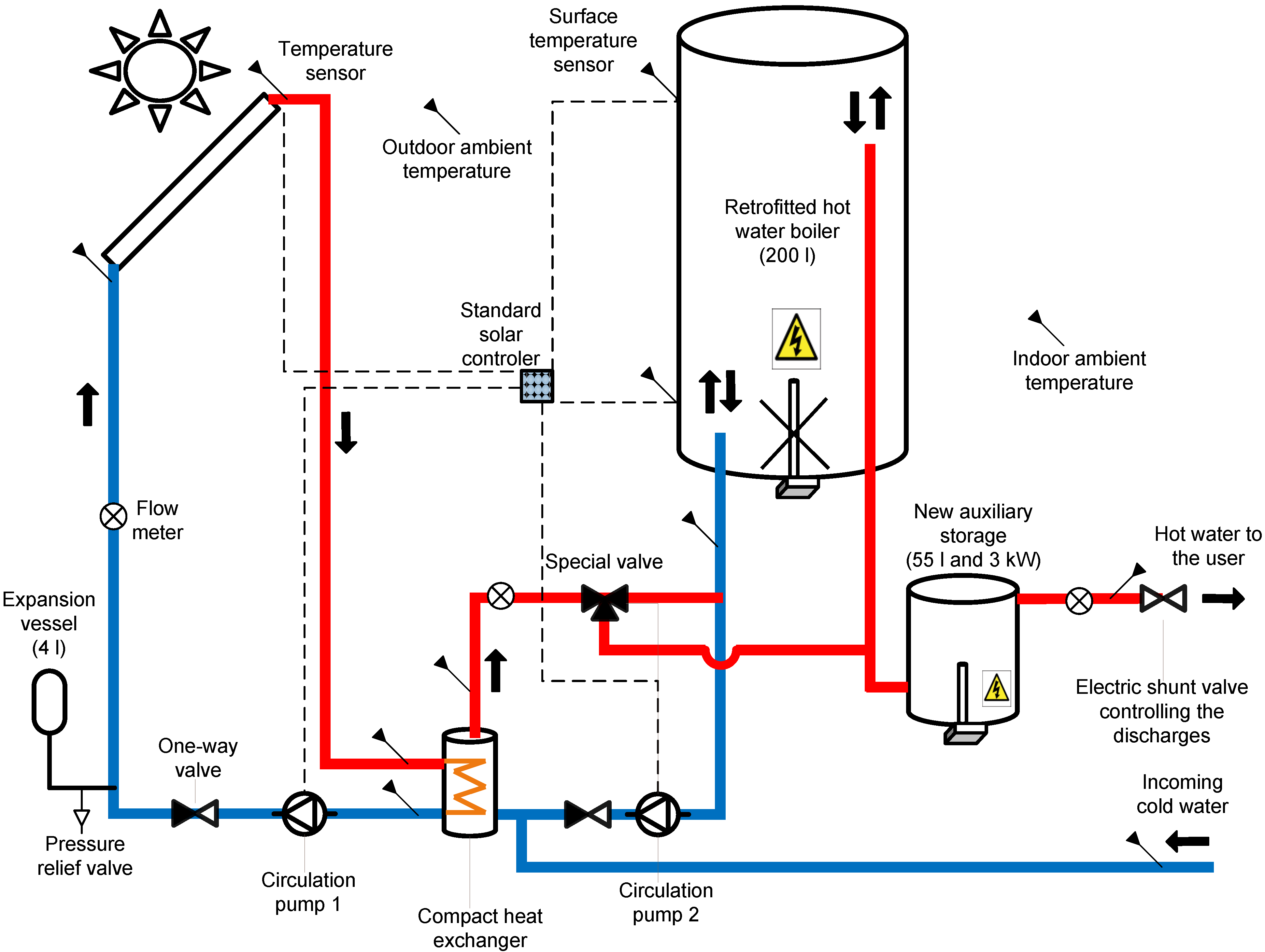
4], since a technical solution for the flow reversion was not yet achieved, it was assumed that charge and discharge could occur simultaneously and independently. Even if this was a simplification of reality it was valid for a comparison of different retrofitting configurations in relative terms. The system was now built in practice and a technical solution was tested to reverse the flow in the connections of the retrofitted storage. The principle is described in the next section and illustrated in
Figure 1. A compact add-on unit that minimizes space requirement and installation costs is advantageous, although there is a trade off between compactness, energy performance and comfort,
i.e., the capability to provide the required hot water temperature to the load. In order to accurately optimize the system energy performance taking into account comfort and compactness, testing and validation of the model was required.
The main objectives of the study were to carry out the validation of the system model and to use it for a system optimization and a sensitivity analysis. The system optimization focused on control strategies for auxiliary heating, heat loss reduction and minimum adequate size of the new auxiliary storage. The sensitivity analysis investigated different DHW load profiles, the size of retrofitted hot water boilers and different climates.
2. System Validation
In this section, the methodology and the results of the model validation are described. A physical description of the system along with an illustration of the model is presented. The validation method consisted of minimizing a target function defined as the absolute difference between the simulated and measured auxiliary energies. The identified parameters that minimize the target function are presented. Also, modelled versus measured results are illustrated graphically and numerically for different time intervals.
2.1. System Description
The retrofitted system consists of connecting in series a new auxiliary storage with a heater to the existing hot water boiler (
Figure 1). This means that the existing boiler is used exclusively for storage of solar hot water, while the new boiler is used for assuring the desired temperature of the hot water. When hot water is drawn off by the user, the water at the top of the retrofitted hot water boiler is pushed to the bottom of the new auxiliary storage and from there to the user.
The two connections of the retrofitted hot water boiler need to be adapted for both hot water discharge and solar energy charge. This was carried out by reversing the direction of the flow in the connections every time a discharge occurs by means of a special valve. During a discharge, the cold water inlet goes to the bottom of the retrofitted hot water boiler via the external heat exchanger. Hence, solar charging during a discharge is possible (
Figure 1). However, during such periods, the charging flow on the tank side is given by the load and not by the pump. In this way the mechanism for the flow reversion, as well as the DHW profile, influences how the charging process occurs and therefore the annual solar fraction. Hence, for increased accuracy, samples from the latest measured DHW loads in 44 Swedish single-family houses were used for selecting the investigated DHW profiles [
22,
23].
Figure 1.
Physical illustration of the retrofitted system tested at the laboratory.
Figure 1.
Physical illustration of the retrofitted system tested at the laboratory.
2.2. Validation of the Simulation Model
The retrofitted system, illustrated in
Figure 1, was modelled according to
Figure 2. The first step of the validation was to select the target parameters that were to be identified. The target parameters are shown in
Table 1 and represent the parameters that were more easily identified by measurements. Also, these were possible to be estimated theoretically allowing the iteration to start with a realistic value. Secondly, an energy balance of the model was carried out. The parameter identification was then carried out between July and December by means of fitting the simulation results to measurements by adjusting the target parameters. This was performed by minimizing a target function using a TRNSYS application called Genopt [
24,
25,
26]. The target function was defined as the absolute difference between the simulated and measured auxiliary energies. Genopt uses algorithms that iterate the target function by changing several system parameters until a minimum is found. Once a set of parameters were identified, simulations and measurement results were compared for a different time period, the validation period between February and June. During this period, tests were carried out at more extreme conditions such as long charge and discharge periods at different flow rates as well as long stand-by periods. This was intended to test the ability of the model to describe other conditions than the ones used for the validation initially. Finally, simulation results were compared with measured temperature profiles during different test sequences.
Figure 2.
Illustration of the validated model along with the identified parameters.
Figure 2.
Illustration of the validated model along with the identified parameters.
The measured data that was fed into the model according to
Figure 2 were the valve control data, the collector fluid and cold water mass flow rates and the temperatures of the collector, cold water, outdoor and indoor ambient. During measurements, data logging was performed every five minutes during roughly one year for 12 temperature sensors, three flow meters and one electric meter.
The results of the parameter identification by matching simulation results with measurements are presented in
Table 1 and shown in
Figure 2. TRNSYS-Genop did not have enough accuracy for defining three different U-values for the retrofitted tank. Therefore, the proportions between them were estimated theoretically so that the target function could identify only one parameter. The identified parameters are in agreement with the ones measured by Cruickshank and Harrison [
27] who showed that three different U-values sufficiently describe the heat losses of a thermal storage.
Table 1.
Results from the parameter identification.
Table 1.
Results from the parameter identification.
| Parameters | Identified | Notes |
|---|
| (W/m2K) | 5 | Includes heat losses from pipes and from singularities. |
| (W/K) | 300 | Product information. The model does not include heat losses. These are accounted for pipe losses. |
| 0.93 | The heat loss coefficient of the retrofitted storage was divided in three where the proportions between them were estimated theoretically. |
| 0.93 |
| (W/m2K) | 1.53 |
| 25 | Calculated based on the temperature profile from test discharges. |
| (°C) | 60 | Parameters of the new auxiliary heater. |
| (W/m2K) | 0.8 |
| (°C) | 8 |
| 1 | Assumed that there is no stratification since the thermostat and electric heater are placed at the bottom of the tank. |
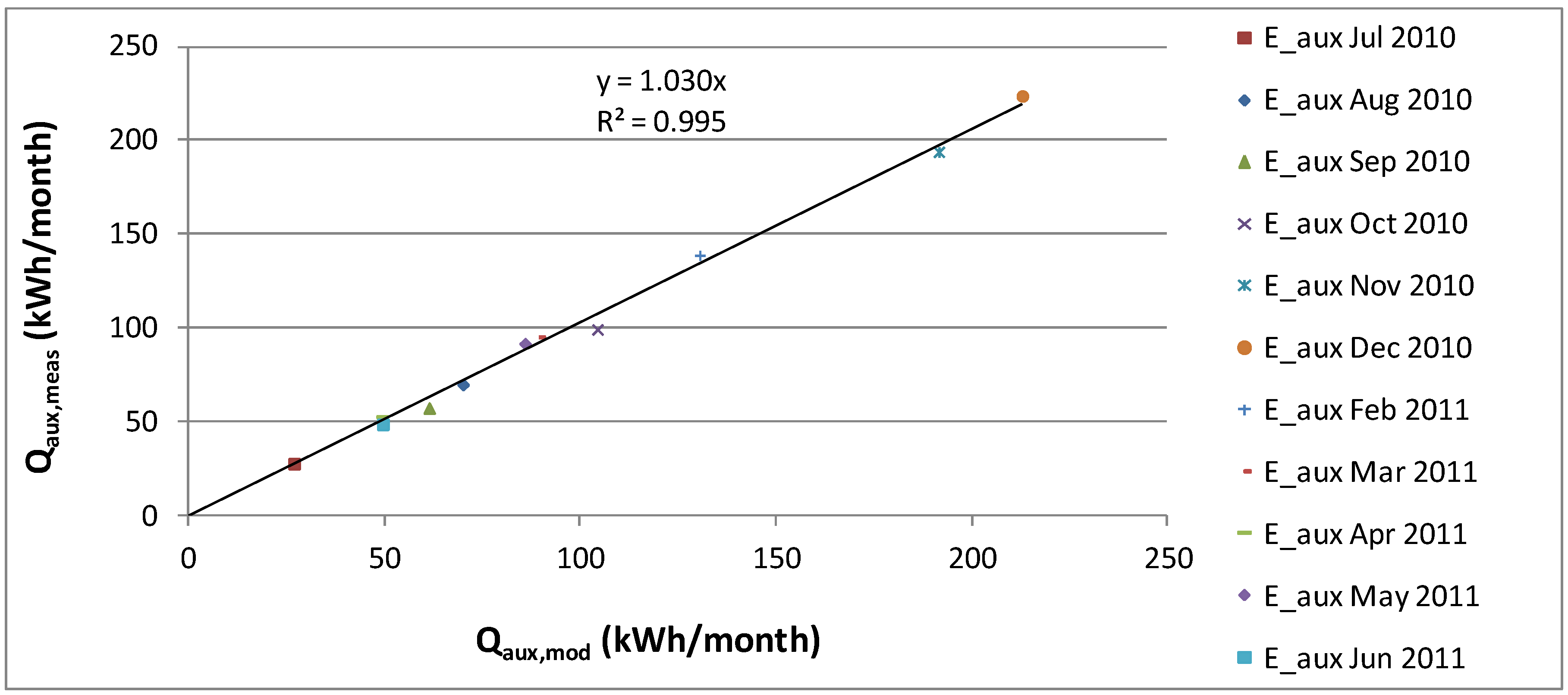
As shown in
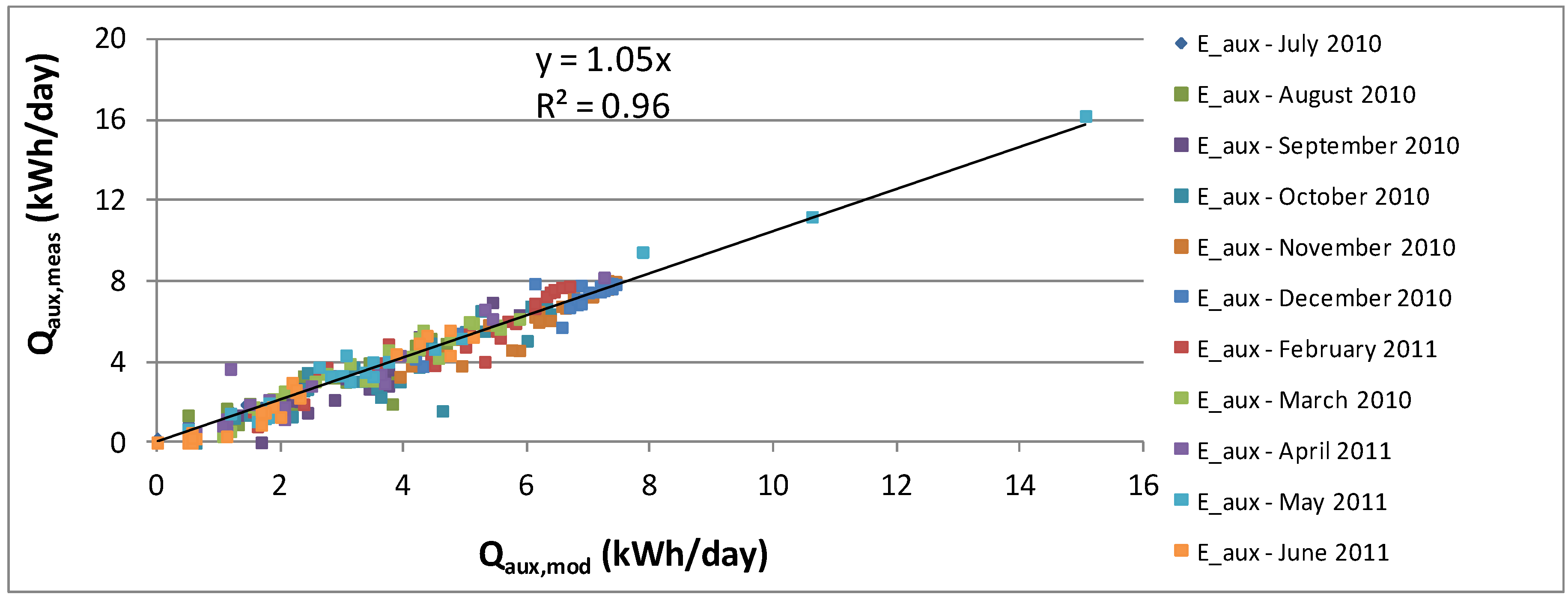
Figure 3, the correlation between the model and measurements on a monthly basis is good. In
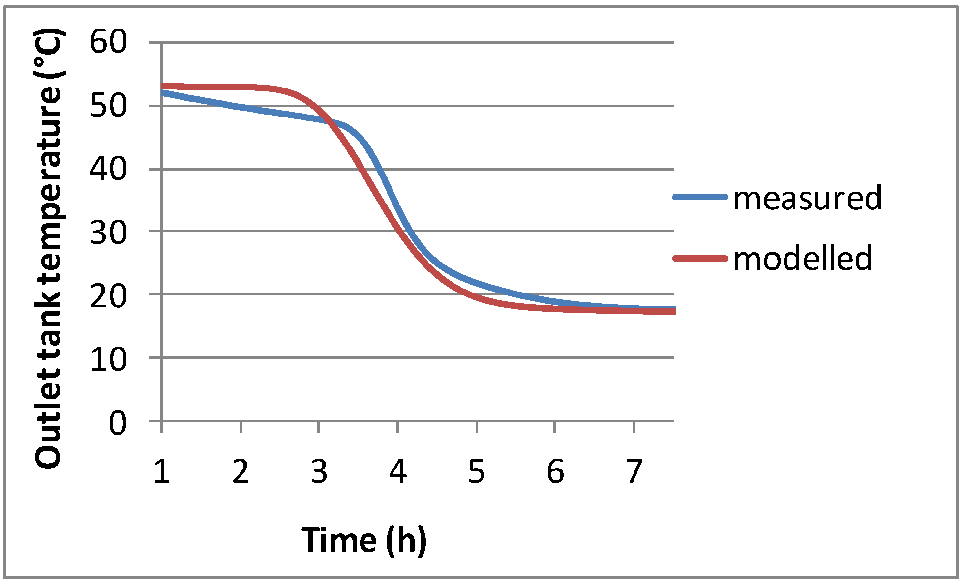
Figure 4 one can see that when presented on a daily basis, the correlation is reduced. One factor that contributes to this is the temperature accuracy of the model. The slope of the temperature profile shown in
Figure 5 suggests that the identified number of nodes that control the stratification of the retrofitted hot water boiler was approximate. The energy content is also roughly the same, however with a different temperature profile. This is mainly due to the difference of the inlet and outlet pipe configurations between the model and reality. In reality, contrarily to the model, the extracted water from the top exchanges heat with the water at the bottom via the metalic outlet pipe that goes through the store and therefore decreases stratification.
Figure 3.
Modelled vs. measured monthly auxiliary energy plotted for the whole period July 2010–June 2011.
Figure 3.
Modelled vs. measured monthly auxiliary energy plotted for the whole period July 2010–June 2011.
Figure 4.
Modelled vs. measured daily auxiliary energy plotted for the whole period July 2010–June 2011.
Figure 4.
Modelled vs. measured daily auxiliary energy plotted for the whole period July 2010–June 2011.
Figure 5.
Measured and modelled temperature profiles of water being discharged from the 200 litres retrofitted hot water boiler previously homogenously heated to 53 °C.
Figure 5.
Measured and modelled temperature profiles of water being discharged from the 200 litres retrofitted hot water boiler previously homogenously heated to 53 °C.
Table 2 shows that TRNSYS-Genopt iterations identified the model parameters in such a way that the total sum of the modelled,
and measured auxiliary energy,
, was very close for the identification period July-December 2010. The accuracy of the model is reduced when the system was tested at more extreme conditions during the validation period. The same applies for the modelled and measured energy provided by the system,
and
.
Table 2.
Sum of the modeled vs. measured auxiliary and provided energy for the different analysed periods.
Table 2.
Sum of the modeled vs. measured auxiliary and provided energy for the different analysed periods.
| TOTAL sum (kWh) | (kWh) | (kWh) | (%) | (kWh) | (kWh) | (%) |
|---|
| Jul–Dec 2010(identification period) | 667 | 672 ± 7 | 0.7 | 1235 | 1236 ± 8 | 0.1 |
| Feb–Jun 2011(validaion period) | 405 | 427 ± 4 | 5.3 | 916 | 938 ± 6 | 2.4 |
| Jul 2010–Jun 2011 (all data) | 1072 | 1099 ± 11 | 2.5 | 2151 | 2174 ± 14 | 1.1 |
3. System Optimization
In this section, the methodology and results for the system optimization are presented. This took into account energy performance, comfort level to the user and add-on unit compactness. The analysis was focused on control strategies for auxiliary heating, reduction of heat losses and minimum adequate size of the new auxiliary storage. Economics were not accounted in this investigation.
The solar fraction was used in order to compare the relative performances of several system configurations. This expression compares the annual energy use of a solar domestic hot water (SDHW) system with a reference DHW system without solar collectors. The solar fraction definitions used in this study were the extended solar fraction,
SFext, and solar fraction indicator,
SFi, described by Equations (1) to (4) [
28,
29].
The first one takes into account not only the required energy from auxiliary heating but also the electricity use by the pumps. There is a risk that this target function leads to a system where the desired DHW temperature is not met at all times. For larger discharges the temperature of the water provided to the user may fall below the hot water temperature requirement during certain periods. Hence, a penalty function for such periods was used [
28,
29]. The
SFi penalises the performance of the system when hot water is provided below the required temperature level. A highly penalising exponential function with a factor of four was used as previously in IEA task 26 and task 32.
SFi does not represent the real fraction of energy savings but can be used to provide information in relative terms regarding how well several systems meet the energy needs within comfort levels. In IEA task 32 it was recommended to verify if the penalty function did not exceed 5% of the total DHW load of the DHW reference system without collectors,
i.e., the penalty fraction,
, where
. This comfort limit is included in the analysis:
where
is one year and
the time step of five minutes. The power,
, of the penalty function was set to 4 [
28,
29] and
defined as:
integrates the energy for periods when the hot water temperature falls below the requirement,
, and is defined as:
A base case scenario was used for the start of the optimization process where adequate improvements were incremented for each analysis. This consists of a 200 litres retrofitted hot water boiler, a 50 litres new auxiliary storage with a 3 kW electric auxiliary heater, Lund climate (Sweden) and 6 m2 solar collectors. A representative DHW profile for this analysis was chosen and is further discussed in the sensitivity analysis. The reference DHW system without solar collectors was defined as a 200 litres hot water boiler with a 3 kW auxiliary heater placed at the bottom with a total DHW load, , of 3448 kWh/y.
3.1. Control Strategies for Auxiliary Heating
In order to improve the comfort level, both the storage size and/or the temperature of the auxiliary heating can be increased. Such variation influences not only the comfort but also the energy performance. Different control strategies for auxiliary heating in both storages were tested.
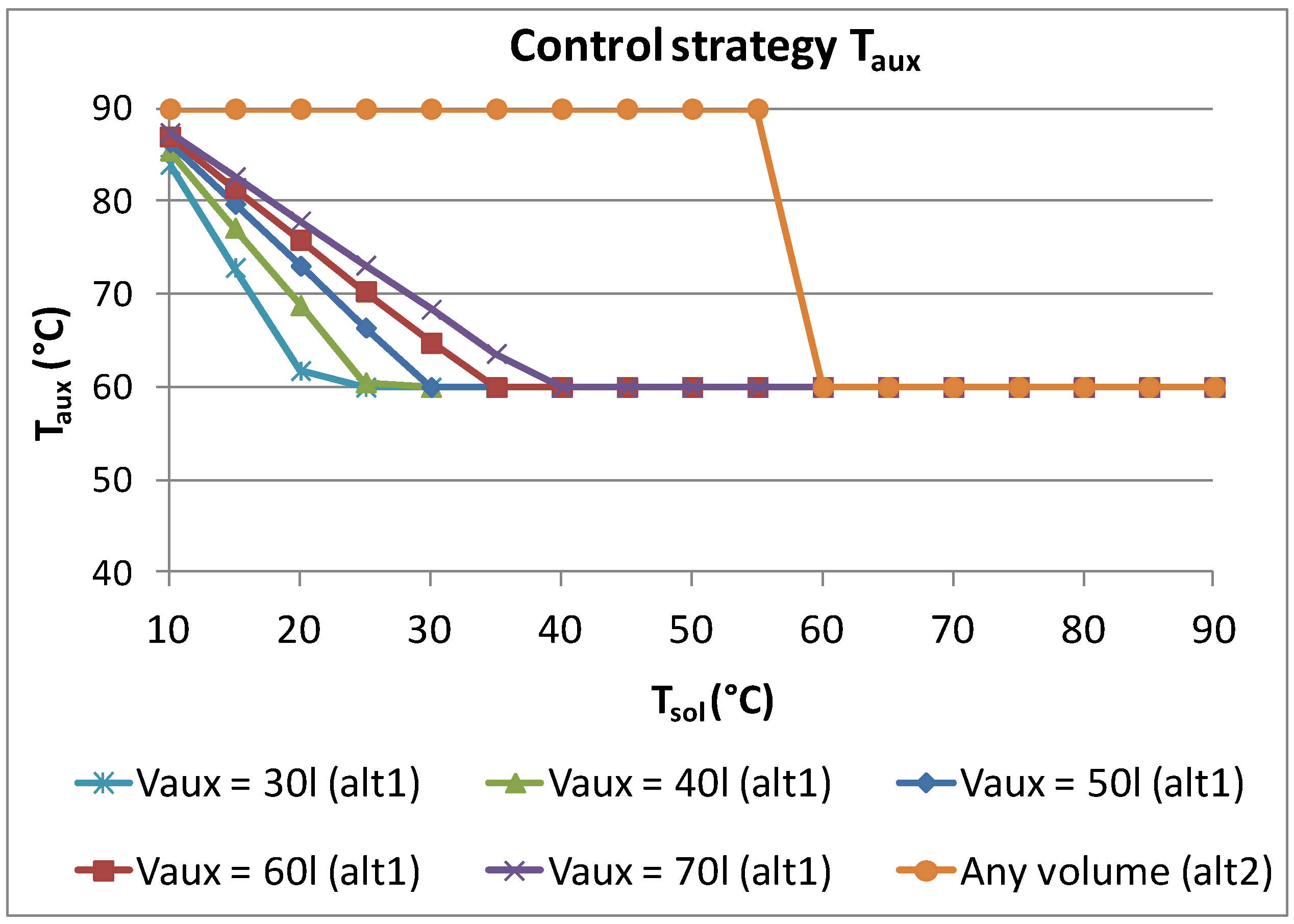
For controlling the heater of the new auxiliary storage two alternatives were analysed (
Figure 6). Both were based on decreasing the temperature setting of the auxiliary heater when higher solar energy was available. Alternative 1 decreases the temperature of the new auxiliary heater proportionally to the increase of the temperature in the highest third of the retrofitted hot water boiler, where the upper temperature sensor is placed. This decrease is such that the combined energy content of both the auxiliary heater and the top third of the retrofitted storage are equal to the new auxiliary storage volume at maximum temperature (90 °C) according to the following equation:
Alternative 2 simply consists of decreasing the auxiliary temperature from 90 °C to 60 °C when the top third of the solar storage is at 60 °C or higher. Hence, the risk of decreasing the comfort level is reduced in comparison with control 1. The results regarding the different control strategies for the heater of the new auxiliary storage are presented in
Table 3, where also the alternatives of a constant auxiliary temperature of 60 °C and 90 °C are included. Control 1 was shown to be the best control in achieving a balance between high solar fraction and comfort level. The energy that could not be delivered for the alternative with the lowest comfort level, 60 °C, was 3.1% of the total DHW load.
Table 3.
Results for the different auxiliary heater control strategies.
Table 3.
Results for the different auxiliary heater control strategies.
| Control | (%) | (%) | (%) |
|---|
| 90 °C | 47.3 | 32.2 | 15.2 |
| 60 °C | 63.7 | 0.0 | 100.0 |
| control 1 | 57.9 | 39.0 | 18.9 |
| control 2 | 49.4 | 34.4 | 15.1 |
A sensitivity analysis on having different power rates for the heater of the new auxiliary storage is presented in
Figure 7. As shown, a higher power increases the comfort for a fairly constant value of the extended solar fraction with the largest variation between 2 and 3 kW. However a higher power than 3 kW might be limited by the electrical installation of the house.
Figure 6.
Alternative 1 and 2 for the control of the new auxiliary heater depending on its volume and available solar energy.
Figure 6.
Alternative 1 and 2 for the control of the new auxiliary heater depending on its volume and available solar energy.
Figure 7.
Sensitivity analysis on the power rates of the new auxiliary heater.
Figure 7.
Sensitivity analysis on the power rates of the new auxiliary heater.
If the desired comfort level is not achieved with a certain size and control of the new auxiliary storage, a pre-set temperature for the heater of the retrofitted hot water boiler can be a solution. Several constant pre-set temperatures were tested ranging from 10 °C (no preheating) to 40 °C. The results are illustrated in
Figure 8 and show that for higher pre-heating temperatures the extended solar fraction decreases faster than the increase in the solar fraction indicator. Control was thus found to be an appropriate optimization and was integrated in the base case system for the following analysis.
Figure 8.
Performance results for the different pre-heating temperatures for the heater of the retrofitted hot water boiler.
Figure 8.
Performance results for the different pre-heating temperatures for the heater of the retrofitted hot water boiler.
3.2. Heat Loss Reduction
The system was optimized with respect to the reduction of the heat losses by gathering the system components into one unit and using control 1. Heat losses from singularities such as sensors, heat exchanger and valves were accounted by the heat losses from the pipes. Gathering the components into one unit decreases these heat losses. Simulations were carried out for the pipe heat loss reduction by 50% and 70%. This was considered reasonable based on a preliminary 3D model improved design where the pipe length was reduced with more than 75% of the current system. The impact on the annual solar fraction of using a low energy pump (19 W) on the tank side was also tested [
30]. The results are presented in
Table 4. A 75% pipe heat losses reduction and a low energy pump were integrated in the base case system for the following analysis. These changes increased the extended solar fraction by roughly 2%.
Table 4.
Results from the heat loss reduction and pump upgrade investigation.
Table 4.
Results from the heat loss reduction and pump upgrade investigation.
| Case description | (%) | (%) | (%) |
|---|
| 0% heat loss reduction | 57.9 | 39.0 | 18.9 |
| 50% heat loss reduction | 58.4 | 38.8 | 19.6 |
| 75% heat losses reduction | 58.6 | 39.3 | 19.3 |
| 75% heat losses reduction and low-e pump upgrade (base case) | 59.7 | 41.8 | 17.9 |
3.3. Different Volumes of the New Auxiliary Storage
In order to increase the comfort level, the volume of the new auxiliary storage can be increased in alternating fashion or in combination with the increase of the heater temperature. This volume is the most important factor influencing the compactness of the add-on unit that includes all the retrofitting components and is therefore advantageous to minimize it. Simulations for different volumes of the new auxiliary storage were carried out until the value of was below 5%. The tested and validated volume of the new auxiliary storage was 55 litres. However, the simulated volumes in this analysis were 20, 30, 40, 50, 60 and 70 litres in order to be closer to standard marketed volumes. The number of nodes and the U-value were kept constant. The heat losses of the storage increase for larger surface areas. The pipe heat losses were reduced with 75% and a low energy pump was used on the tank circuit.
The results are presented in
Figure 9 and show that for higher volumes the comfort level is improved for a fairly constant value of the extended solar fraction. The largest variation occurs between 40 and 50 litres. For
below 5%, the minimum required size for the new auxiliary storage is 70 litres. For such configuration,
equals 58%,
56% and
2%. During winter periods when no solar energy is available and only the new auxiliary heater provides hot water (at 90 °C), a total of 187 litres at 40 °C can be provided by this system which roughly corresponds to six showers of 30 litres at the same time. For such system the total amount of discharges, for which the provided hot water temperature was below the requirements, were 12 out of 6485 during one year. The energy that was failed to be delivered due to this temperature drop was 0.1% of the total DHW load,
. To meet unusual large loads the user has the possibility to turn on the heater of the retrofitted hot water boiler.
Figure 9.
Sensitivity analysis on different auxiliary storage volumes.
Figure 9.
Sensitivity analysis on different auxiliary storage volumes.
4. Sensitivity Analysis
A sensitivity analysis was performed for three different DHW load profiles, several volumes of the retrofitted hot water boiler between 40 litres and 400 litres and for three different climates.
4.1. Different DHW Load Profiles
Since the load profile can influence the system performance, three different measured DHW load profiles were analysed with different annual energy loads for single-family houses with three inhabitants. These cover a full month and were extrapolated to represent one whole year while adjusted by a seasonal factor [
31].
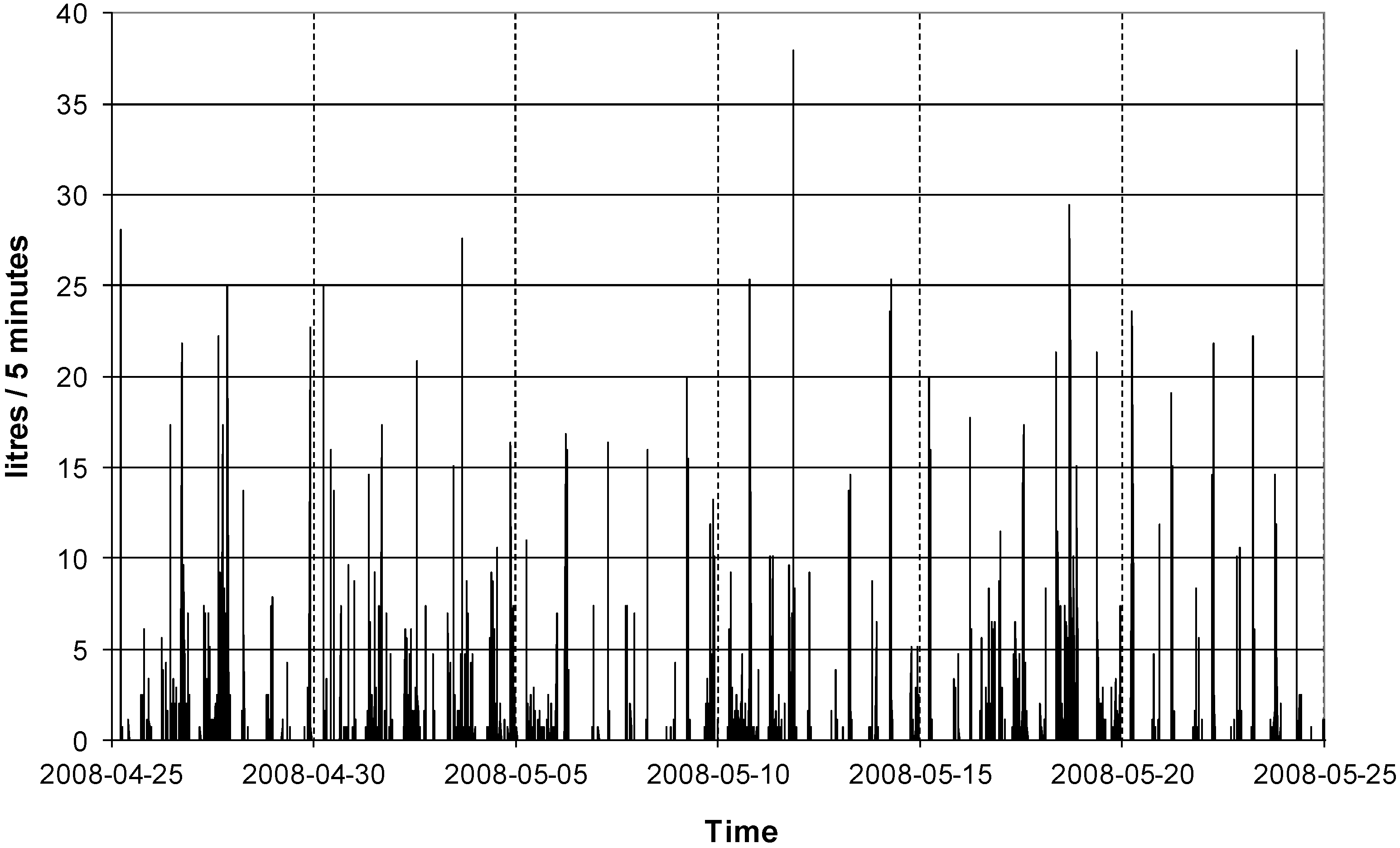
Figure 10 and
Figure 11 show DWH profile 2. This was used in the base case scenario for the optimization process since its estimated annual load matches the measured average of the 44 measured DHW profiles [
22]. For simplicity, only DHW profile 2 is presented in detail. The total annual load for the other DHW profiles and the simulation results are presented in
Table 5. The total number of discharges during a year for DHW profiles 1, 2 and 3 are 7390, 6485 and 3764, respectively. The energy that could not be delivered was less than 0.1% of the total DHW load, for the three profiles.
Figure 10.
Illustration of the measured monthly domestic hot water profile 2 which was used in the annual simulations.
Figure 10.
Illustration of the measured monthly domestic hot water profile 2 which was used in the annual simulations.
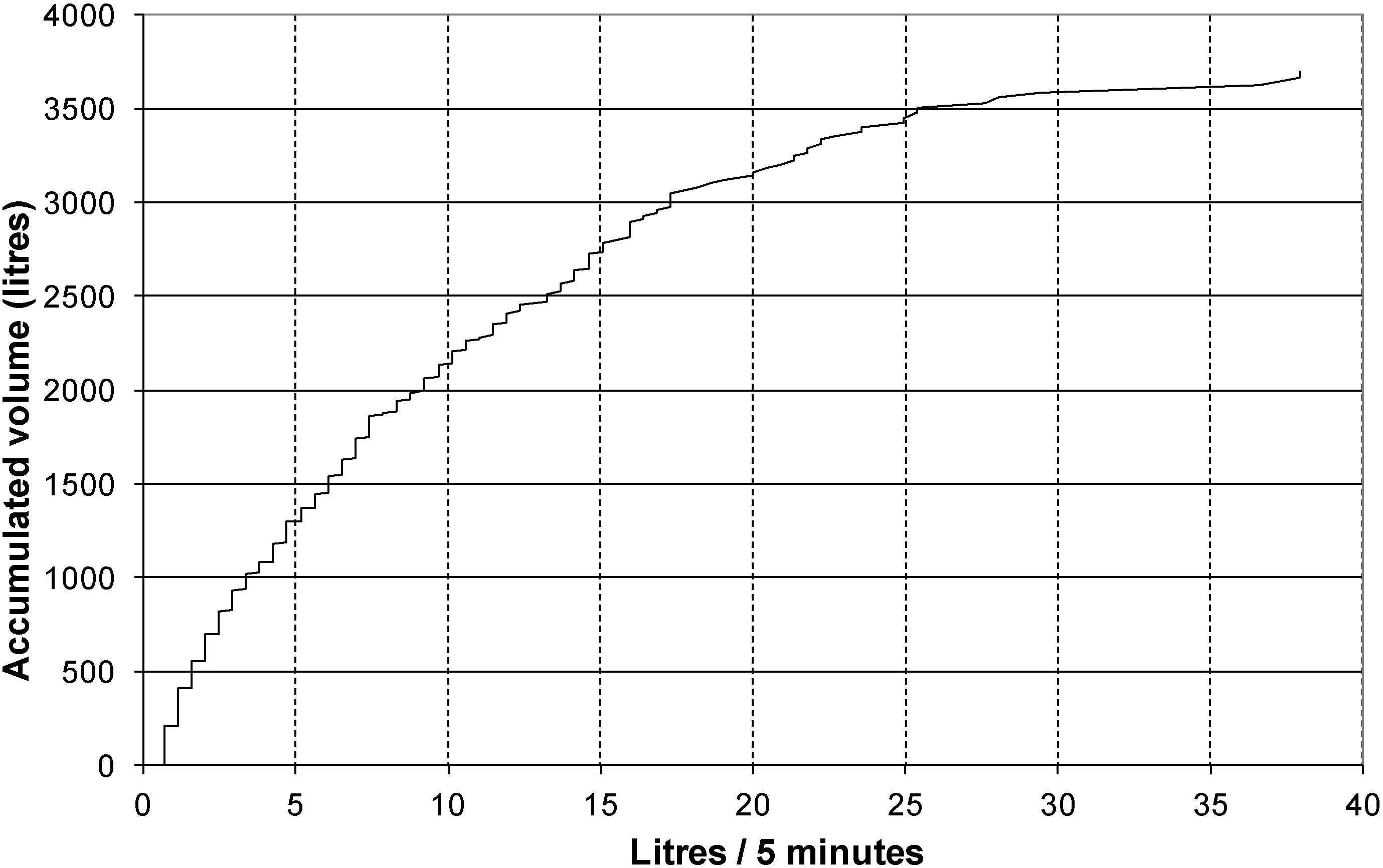
Figure 11.
Illustration of the accumulated volume per flow rate for the measured monthly domestic hot water profile 2 which was used in the annual simulations.
Figure 11.
Illustration of the accumulated volume per flow rate for the measured monthly domestic hot water profile 2 which was used in the annual simulations.
Table 5.
Performance of the retrofitted system for three different domestic hot water profiles.
Table 5.
Performance of the retrofitted system for three different domestic hot water profiles.
| DHW profile # | (%) | (%) | (kWh/y) | (%) |
|---|
| 1 | 57.0 | 56.9 | 5832 | 0.1 |
| 2 | 57.8 | 55.6 | 3449 | 2.2 |
| 3 | 71.6 | 70.4 | 2972 | 1.2 |
4.2. Different Volumes of the Retrofitted Hot Water Boiler
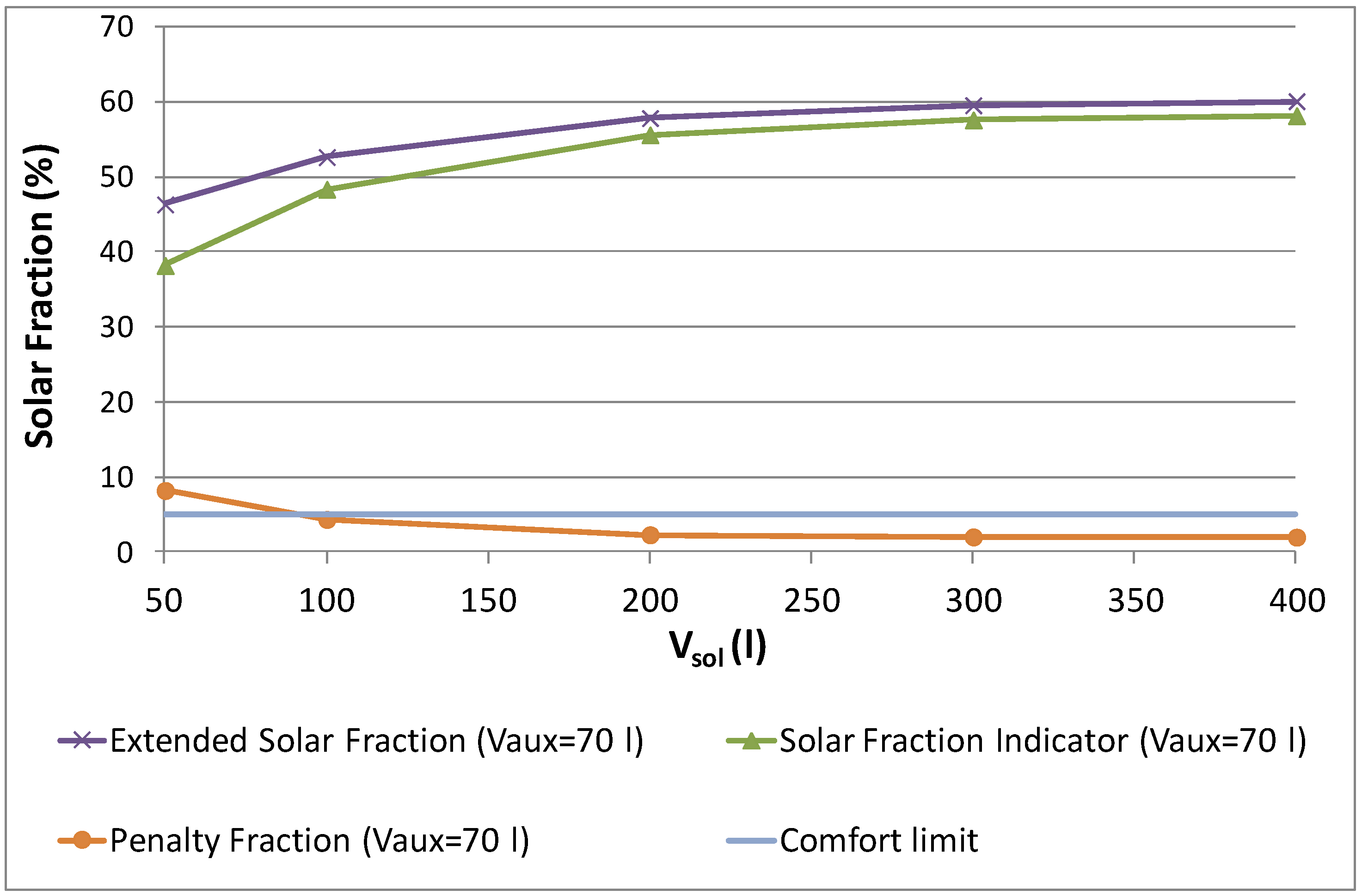
The existing hot water boiler for the retrofitting can vary in size. It is therefore important to be aware of the comfort and energy performance levels regarding different sizes of retrofitted boilers. A sensitivity analysis was performed in the range of 50–400 litres for 70 litres volume of the new auxiliary heater (good comfort case). It was assumed that the height increased in proportion to the volume. The number of nodes and the U-value were kept constant. The heat losses of the storage increase for larger surface areas. The results are illustrated in
Figure 12 and further considered in the Discussion section.
Figure 12.
Sensitivity analysis on different volumes of the retrofitted storage.
Figure 12.
Sensitivity analysis on different volumes of the retrofitted storage.
4.3. Different Climates
The distribution of the solar radiation throughout the year in different climates influences not only the extended annual solar fraction,
, but also the number of discharges below comfort level and therefore the solar fraction indicator,
. The climates in Lund (Sweden, lat: 55.7° N), Lisbon (Portugal, lat: 38.7° N) and Lusaka (Zambia, lat: 15.4° S) were evaluated for collector areas of 6, 4 and 3 m
2, respectively. Such areas represent a balance between a high solar fraction and a reduced number of collectors. The tilt was close to optimal for each site and equal to 40°, 30° and 20° from horizontal, respectively. The volume of the new auxiliary storage that ensured that
was below 5% were 70, 50 and 50 litres, respectively. The results in different climates and for different control strategies are shown in
Table 6.
Table 6.
Performance of the retrofitted system in different climates for different auxiliary heating controls.
Table 6.
Performance of the retrofitted system in different climates for different auxiliary heating controls.
| Location | Control type | (kWh/y) | (%) | (%) | (%) |
|---|
| Lund (Sweden) | 90 deg | 1847 | 46.4 | 43.5 | 3.0 |
| 60 deg | 1246 | 63.9 | 0.0 | 100.0 |
| control 1 | 1455 | 57.8 | 55.6 | 2.2 |
| Lisbon (Portugal) | 90 deg | 1304 | 62.2 | 59.0 | 3.2 |
| 60 deg | 248 | 80.3 | 15.5 | 64.9 |
| control 1 | 765 | 77.8 | 73.6 | 4.4 |
| Lusaka (Zambia) | 90 deg | 1280 | 62.9 | 60.6 | 2.3 |
| 60 deg | 603 | 82.5 | 63.7 | 18.9 |
| control 1 | 657 | 81.0 | 76.6 | 4.4 |
5. Discussion
A limitation on the TRNSYS-Genopt validation method is that other combinations of identified parameters could possibly provide a better fit to the measured results. Also, further improvements could have been carried out on the model to take into account the heat exchange between the water in the retrofitted hot water boiler storage and the pipe placed from top to bottom (
Figure 1). However, this was considered to be unnecessary taking into account the model accuracy that was required. The goal with the model validation was to achieve reliable results for the solar fraction at an annual basis while the agreement between model and measurements at a daily basis was less important. This was accomplished with the presented model.
Since the validated model was used for other boundary conditions than during the test, it is difficult to quantify its uncertainty, especially since the DHW load profile used in tests was significantly different from the one in simulations. Some factors decreasing its accuracy are the model simplifications regarding the retrofitted hot water boiler and its inlets/outlets, the assumption of a constant numerical relation between the three U-values of the retrofitted hot water boiler, the assumption that the upper and middle U-values would be the same and the difficulty to estimate the dead-band of the auxiliary heater, since there was no sensor placed inside the new auxiliary heater tank. Both the identified values for the pipe and storage U-values are however in accordance with previous studies [
27,
28].
The solar fraction indicator, , evaluates the comfort level in a subjective way. It is difficult to state whether “good” comfort levels are ensured for a penalty value below 5% of the total DHW load or for other value. Also, the power factor, , equal to 4 seems very penalizing and has a big influence in this result. In fact, if the power factor was reduced to 2, a 50 litres volume of the new auxiliary storage would be enough to guarantee that was below 5% in Lund instead of 70 litres as it was shown. Since the scope of this study did not include new definitions of performance and comfort levels, it was decided to use previous definitions such as the ones used by IEA task 24 and 32 and mark the points within the comfort level according to them. No distinction was made between different types of energy or their sources. Nevertheless, necessary information is provided for a recalculation.
Among the analysed controls, Control 1 was shown to be the best in achieving a balance between high solar fraction and comfort level. This is due to the fact that lower auxiliary temperatures in the series connection configuration allow higher volumes of cold water inlet in the solar storage which increases the solar collector working hours and efficiency. The user has also the option of manually regulating the termostat of the new auxiliary heater from 60 to 90 °C. Also, for a great increase in capacity, the heater of the retrofitted hot water boiler can also be turned on. It is difficult to predict how a user will regulate the thermostat or even eventually change its own consumption pattern with such auxiliary controls [
32]. More advanced controls such as predictive behaviour controls could be further investigated and tested in a real application [
33].
The volume of the new auxiliary storage has a large influence on the comfort level and a limited impact on the extended solar fraction due to its low influence on the stored amount of solar energy. Higher volumes of this storage provide a better comfort but also higher heat losses which causes the extended solar fraction to decrease sligtly (
Figure 9). This strong influence on comfort can be a disadvantage since it requires an increase in volume of the retrofitting add-on unit. On the other hand it allows the comfort level to be mainly controlled by the manufacturer. The manufacturer can also control the insulation level of the new auxiliary storage which is, among other factors, significantly more important for the system performance than that of the retrofitted hot water boiler [
34].
The sensitivity analysis on different climates showed that for climates where the solar irradiation is more distributed along the year, a volume of the new auxiliary storage of 50 litres would be enough to achieve good comfort levels. The analysis also showed that for DHW load profiles with significantly different annual loads the comfort level is still good. Finally, and contrarily to the new auxiliary storage, the volume of the retrofitted hot water boiler significatly influences the solar storage capacity and therefore the
It was shown in
Figure 12 that, for volumes of the retrofitted hot water boiler between 100–400 litres, the
varies by roughly 7 percentage points. This variation does not seem to be critical and, since it is expected that the most common sizes of boilers in Sweden are between 200–300 litres [
35], the retrofitting possibilities should be favourable. The volume of the retrofitted hot water boiler also impacts the comfort level but decreasingly for higher volumes of the new auxiliary storage. The biggest comfort problem occurs in the winter time when there is less available solar hot water and when therefore that volume is less important.
To engineer a compact add-on unit is importnant not only for the heat losses decrease but also to decrease the space requirement and installation costs of the add-on unit. It is difficult to evaluate how important the compactness of the retrofitting component is for the user. This is relevant since there is a trade off between compactness (low volume of the new auxiliary storage) and energy performance and comfort. This study provides the necessary information to design the system according to the importance of these factors. Once costs of production for certain market volumes can be determined, an optimization process focused on cost efficiency can be carried out.
6. Conclusions
A retrofitted solar thermal system was evaluated and the simulation models validated against measurements. These results were used to carry out a sensitivity analysis on several improvement possibilities. The adjusted model was shown to be in agreement with the measurements with a deviation of 2.5% out of 1099 kWh of auxiliary energy on an annual basis.
The results from the optimization process showed that one of the investigated control strategies for auxiliary heating increased the extended solar fraction significantly by roughly 11 percentage points with a relatively small compromise on the comfort level. Also, by gathering the retrofitting components into one unit the pipe heat losses were estimated to decrease. In combination with a low energy pump the extended solar fraction was estimated to increase by roughly two percentage points. Furthermore, for the climate of Lund in Sweden, the minimum adequate size of the new auxiliary storage that achieves good comfort was found to be 70 litres equipped with a 3 kW heater. With such improvements and retrofitting a hot water boiler of 200 litres using 6 m2 of collector area the system achieved an extended solar fraction of 58%.
The sensitivity analysis on different volumes of retrofitted hot water boilers showed that between 100–400 litres the extended solar fraction was reduced roughly by 7 percentage points while achieving good comfort levels, even for other DHW load profiles. For climates where the annual irradiation is more distributed, a volume of 50 litres of the new auxiliary storage would be enough to reach comfort levels for the climates in Lisbon (Portugal) and Lusaka (Zambia). For these climates, extended solar fractions of 78% and 81% can be achieved with the use of 4 and 3 m2 collector areas, respectively.
The studied retrofitted system achieves therefore a comparable performance with conventional solar thermal systems in single-family houses with the potential to significantly reduce the investment cost for solar heating of domestic hot water.


