Evaluation of Biofuel Cells with Hemoglobin as Cathodic Electrocatalysts for Hydrogen Peroxide Reduction on Bare Indium-Tin-Oxide Electrodes

Abstract
: A biofuel cell (BFC) cathode has been developed based on direct electron transfer (DET) of hemoglobin (Hb) molecules with an indium-tin-oxide (ITO) electrode and their electrocatalysis for reduction of hydrogen peroxide (H2O2). In this study, the ITO-coated glass plates or porous glasses were prepared by using a chemical vapor deposition (CVD) method and examined the electrochemical characteristics of the formed ITO in pH 7.4 of phosphate buffered saline (PBS) solutions containing and not containing Hb. In half-cell measurements, the reduction current of H2O2 due to the electrocatalytic activity of Hb increased with decreasing electrode potential from around 0.1 V versus Ag|AgCl|KCl(satd.) in the PBS solution. The practical open-circuit voltage (OCV) on BFCs utilizing H2O2 reduction at the Hb-ITO cathode with a hydrogen (H2) oxidation anode at a platinum (Pt) electrode was expected to be at least 0.74 V from the theoretical H2 oxidation potential of −0.64 V versus Ag|AgCl|KCl(satd.) in pH 7.4. The assembled single cell using the ITO-coated glass plate showed the OCV of 0.72 V and the maximum power density of 3.1 µW cm−2. The maximum power per single cell was recorded at 21.5 µW by using the ITO-coated porous glass.
1. Introduction
Biofuel cells (BFCs) are clean and renewable power sources which directly convert chemical energy into electrical energy, typically utilizing the electrocatalytic functions of living cells, such as bacteria and algae or proteins and organelles extracted from the cells such as enzymes and mitochondria [1,2]. Recently, BFCs have attracted great interest as the power supplies for a cardiac pacemaker, toys, integrated circuits, or relatively low electrical power devices to keep the environment safe and establish a sustainable society, since the systems operate under mild conditions at around body temperature of 20–40 °C in near-neutral pH as well as natural materials can be utilized in the electrode process [3–15].
It has been probably defined that only systems where the electron tunnels directly between the active site in the enzyme and the electrode or an individual enzyme having reaction active and electron carrying sites show the electron transfer with the electrode directly are direct electron transfer (DET) type electrodes, and the other all electrodes are classified into mediated electron transfer (MET) types [2,10]. Since the potential range for the BFC based on DET is generally close to the redox potential of the enzyme itself, it can be expected a high power-output as well as simplicity of the electrode compared with the MET-type BFCs. However, most enzyme proteins show slow electron transfer characteristics with the electrodes. One interpretation of this fact has been attributed to the distance between the electrode surface and the reaction active sites in the enzyme proteins because enzymes usually have a large protein structure and the reaction active site is embedded deeply in the protein shell.
Peroxidases are known as the enzymes which typically metabolize hydrogen peroxide (H2O2) and have attracted the attention for the DET-type electrodes since the reaction active sites are located near the surface of protein shell [2]. In the case of the peroxidase having a single heme group, such as horseradish peroxidase (HRP), which exhibits the DET with the electrode, the orientation of the enzyme on the electrode surface is crucial for the distance of the heme site from the electrode surface and for the activity of the electron transfer including the diffusion pathway of the substrate to the heme site [14]. Catalase is a tetrameric heme enzyme composed of four heme groups that allow it to react with H2O2 and produce water and oxygen. However, the huge protein structure with a molecular weight (MW) of 240 kDa of catalase implant the heme deeply inside the protein shell and brought about poor electron transfer on bare electrode surfaces [16,17]. Therefore, few reports have mentioned the development of high performance BFCs based on the DET of enzyme proteins, even in recent year [10,14,18,19].
Hemoglobin (Hb) is typically known as a tetrameric heme protein composed of two α-globin and two β-globin polypeptides similarly to catalase, however, the molecular size of Hb with MW of 64 kDa and the dimension of 50 × 55 × 64 Å3 is close to that of HRP with MW of 44 kDa and the dimension of 62 × 43 × 12 Å3 and four iron-bearing heme groups are located near the surface of the protein shell [20–22]. In the Hb electrochemistry, it has been believed that the strong adsorption of proteins onto the electrode surfaces brings about a denaturation of the protein structure and the slow electron transfer characteristics with the electrodes. Thus, the electrochemical investigations have been mainly performed with the modified or immobilized, i.e., by the MET-type, electrodes [23–34]. On the other hand, we have observed the DET between the Hb molecules and indium-tin-oxide (ITO) electrodes and found that the protein structure of Hb molecules on the bare ITO electrode surface should be similar to its own native state such as same as that in the solution phase [35,36]. Recently, we developed a novel BFC based on the DET of the Hb molecules, reducing H2O2 to water at the cathode, on the ITO electrodes [37,38].
The BFC cathode utilizing the Hb-ITO system has some unique advantages: (i) it has potential for development of high performance BFC utilizing DET with a simple electrode structure; (ii) Hb is a low cost bio-material compared with other enzymes or rare metals such as bilirubin oxidase or platinum (Pt), and is renewable in the life circle of organizations; and (iii) as applied in an oxygen reduction cathode, which is proceeded with only two electron reduction producing H2O2 or totally four electron reduction consisting of two and two electron reduction to water, i.e., fully oxygen reduction via H2O2, it can be expected a promotive effect for the electrocatalysis of the electrode with four electron reduction of oxygen.
In this study, we prepared ITO-coated glass plates and porous glasses by using a slightly customized chemical vapor deposition (CVD) method [39,40] to enhance the cathodic performance by enlarging the specific electrode surface area, and half-cell and single cell tests were carried out based on the reduction of H2O2 with the Hb-ITO system.
2. Results and Discussion
2.1. Cyclic Voltammograms (CVs) for DET between Hb Molecules and ITO Electrodes
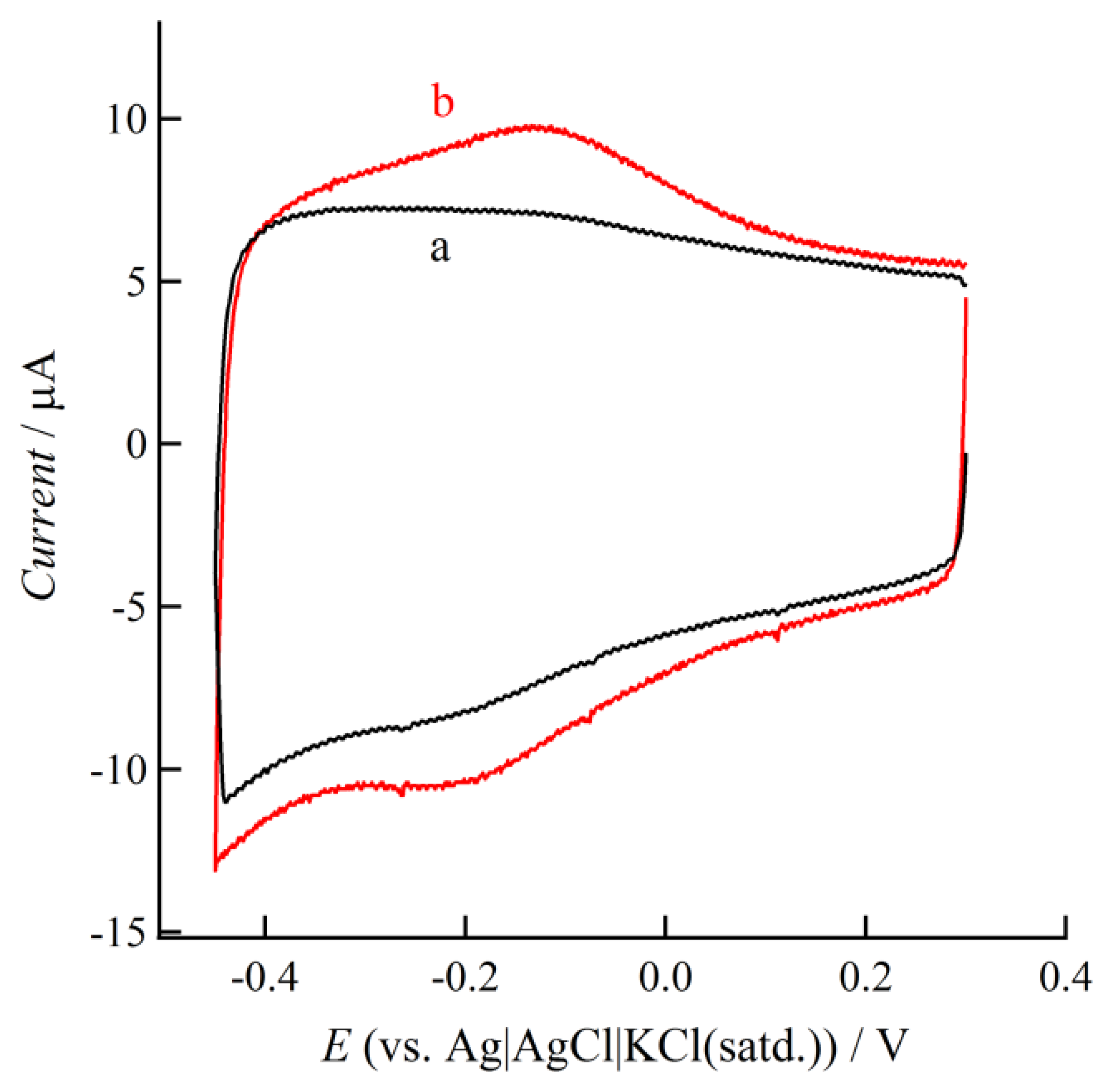
Figure 1 shows the CV curve observed at the prepared ITO electrode in Hb absent and present phosphate buffered saline (PBS) solutions.
A pair of redox peak currents was observed at around −0.127 V and −0.189 V in the Hb containing solution. The formal potential of heme Fe(II)/Fe(III) couple of Hb was estimated to be −0.158 V. The quantity of electrochemically active Hb molecules can be calculated from an integration of charge, Q, in CVs by using an equation:
The open-circuit voltage (OCV) for the BFCs utilizing the H2O2 reduction by Hb-ITO systems at the cathode can be expected from the formal potential, E0′, of the reaction. In this study, we employed a hydrogen (H2) oxidation at Pt in the anode and the H2O2 reduction at the Hb-ITO system in the cathode as the fuel cell reactions of the single cell. The total reaction can be represented from the anodic and cathodic reactions as follows:
anodic reaction:
cathodic reaction:
total reaction:
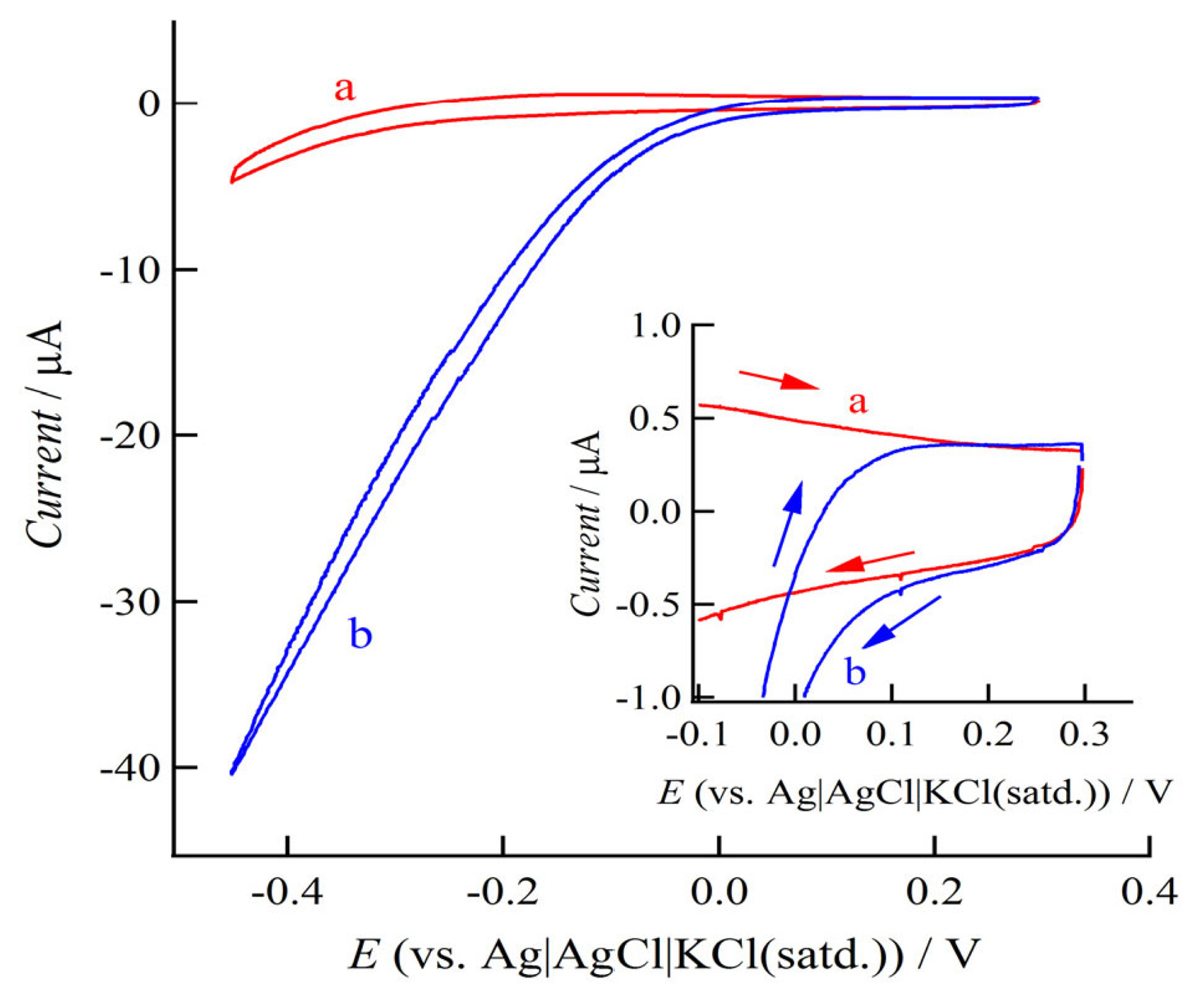
Figure 2 shows the CVs recorded with 0.01 V s−1 at ITO electrodes in H2O2 absent and present Hb containing PBS solutions.
In the H2O2 present solution, an on-set potential of H2O2 reduction by the electrocatalysis of Hb could be determined around 0.1 V, indicating the formal potential of H2O2 reduction on the Hb-ITO system. On the other hand, the formal potential of the H2 oxidation could be expected by using the theoretical redox potential of it represented by versus a standard electrode potential (SHE). In this study, we used the Ag|AgCl|KCl(satd.) as the reference electrode and the pH 7.4 of PBS solution as the electrolyte, thus, the SHE of H2 oxidation can be represented to be −0.64 V. Consequently, the OCV for the single cell composed of the H2O2 reduction cathode on Hb-ITO systems and H2 oxidation anode could be expected to be at least 0.74 V.
2.2. Performance of BFCs Utilizing Hb-ITO Systems
In the single cell type I, the maximum power density was observed at around 0.15 µW cm−2 and superposed in Figure 3B(a), while the observed OCV were 0.34 V [38]. However, it can be expected further high performance for a single cell based on the DET and the reduction of H2O2 at the Hb-ITO cathode from the half-cell measurements as shown in Figure 2. In the single cell type I, H2 gas was supplied by the bubbling solution, thus the dissolved H2 in PBS solution would be the main reaction species in the anode, indicating the considerably low concentration of reactant at the anode and the cross-over phenomena of H2 to the cathode.
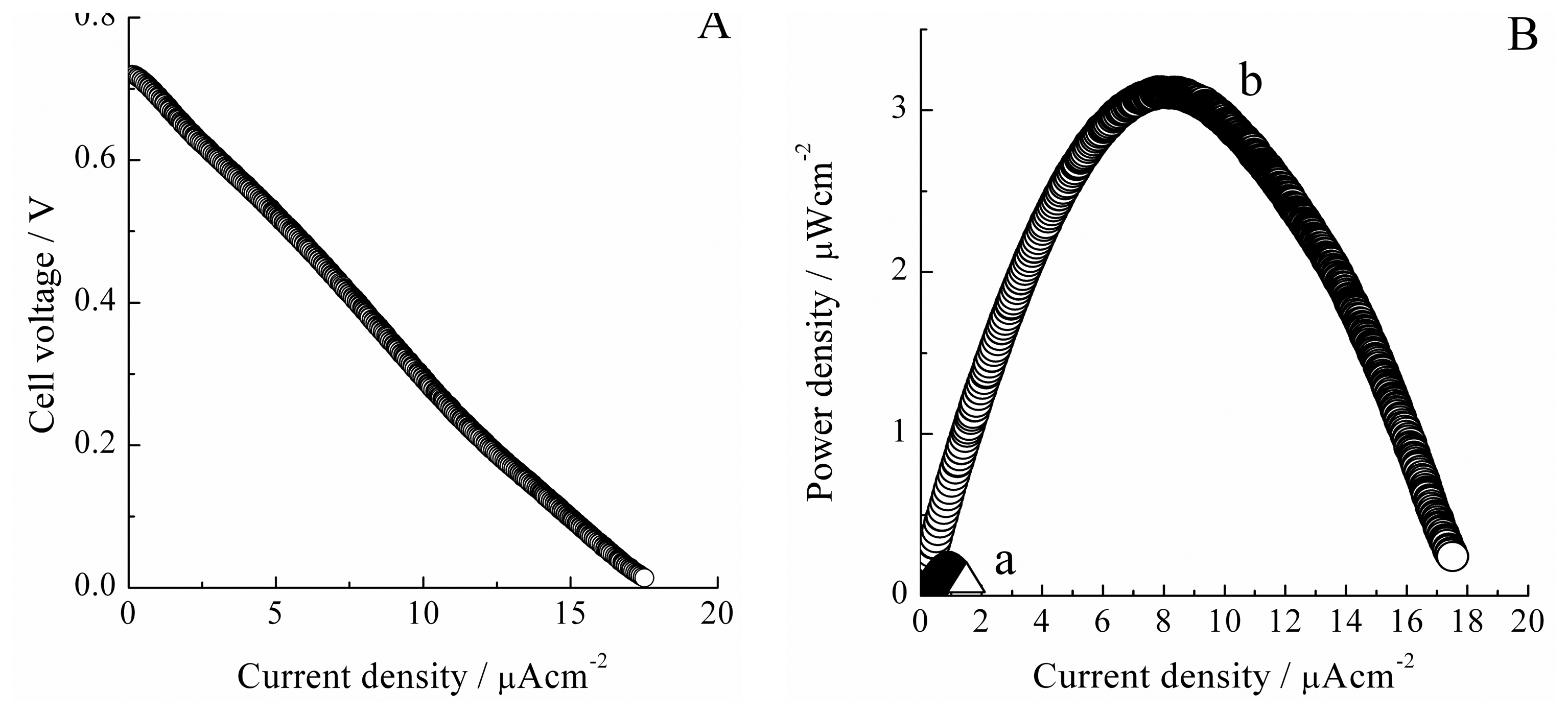
In this study, we examined the I-V characteristics on the single cell with the MEA in the anode. Figure 3A shows the I-V characteristics recorded with the sweep rate of 50 nA−1 in the single cell type II. The cathode was composed of 5 µM Hb and 1.8 mM H2O2 containing PBS solution and the prepared ITO-coated glass plate electrode. The OCV of this cell was observed at around 0.72 V. The improved OCV would indicate the inhibition of the cross-over phenomena of H2 to the cathode because H2 gas was not supplied to the electrolyte directly but from the backside of the electrodes. The power density was calculated from the data of the I-V characteristics and plotted in Figure 3B(b). The power density characteristics were improved approximately 20-fold from those of the single cell type I as seen in Figure 3B(a). The origin of the improvement of the power characteristics should be mainly attributed to the anode, since the construction of the cathode was almost the same as that in the single cell type I. Since the H2 gas diffused in the Pt dispersed layer, the oxidation of H2 should mainly occur at the three-phase boundary consisting of gas/liquid/solid interfaces in the anode, indicating the increasing concentration of H2 and the enlarged active surface area for H2 oxidation. Additionally, the PBS solution phase in the anode side was removed and Nafion® membrane directly adhered to the Pt dispersed layer, thus, it was expected to decrease the solution resistant of the electrolyte. Consequently, we successfully obtained a maximum power density of 3.1 µW cm−2 at around 7.9 µA cm−2 on the single cell applying the Hb-ITO system based on the DET and the electrocatalysis for the reduction of H2O2 in the cathode.
The performance on the single cell type II were close to that approximately estimable from the reduction current of H2O2 observed in CVs with low sweep rate, i.e., in Figure 2. In addition, since the diffusion-limited current was not observed in the I-V characteristics shown in Figure 3A, the mass transfer limitation of H2O2 and H2 would be almost negligible in the single cell type II. This indicated that the cathodic reaction kinetics would be the rate-determining step. Thus, further high single cell performance would be obtained by improving cathodic construction. In this study, we evaluated the performance of the single cell by utilizing the ITO-coated porous glass at the cathode, i.e., the single cell type III, to increase the specific surface area of the electrode and the detailed cell construction is shown in Figure 4c.
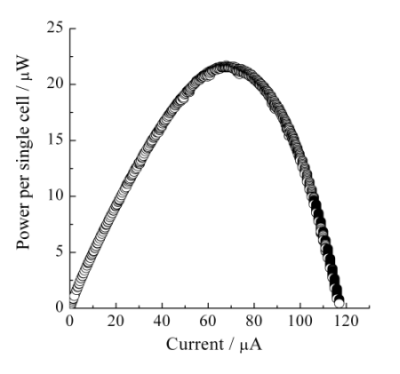
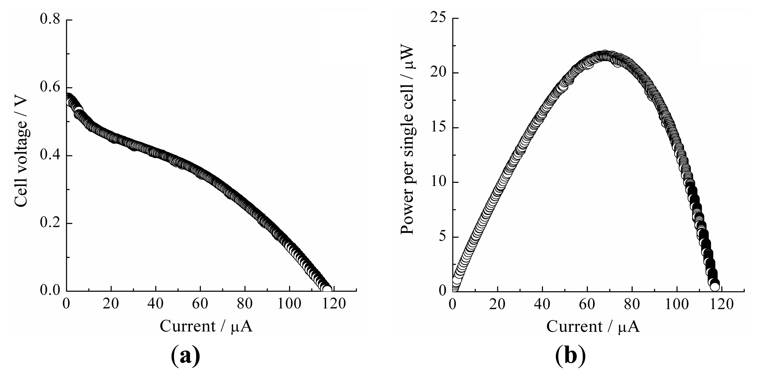
Figure 5a shows the I-V characteristics recorded with the sweep rate of 50 nA s−1 on the single cell type III. The observed OCV was 0.57 V. This value was lower than that of the single cell type II. In the single cell type III, the Nafion® membrane was directly contacted and pressed with the ITO porous glass. It was most likely that the thin electrolyte layer and/or the mechanical, physical, and morphological change of the Nafion® membrane might bring about the cross-over phenomena of H2 and H2O2. Although it was difficult to discuss for the I-V characteristics at the high current range over 60 µA in Figure 5a, typical diffusion-limited current would not be observed, indicating further potentiality for developing high performance BFC cathode. The power characteristics on single cell type III were considerably improved and the maximum power per single cell was observed at around 21.5 µW, as shown in Figure 5b. This improvement of the single cell performance should be attributed to the enlarged active surface area of the cathode composed of Hb-ITO systems.
3. Experimental Section
3.1. Chemicals
Indium (III) chloride tetrahydrate (InCl3·4H2O) (purity, 99.9%), tin (II) chloride dihydrate (SnCl2·2H2O) (purity 99.9%), and ethanol (purity, 99.8%) were purchased from Wako Pure Chemical Industries, Ltd. (Osaka, Japan). The solution was prepared using InCl3·4H2O and SnCl2·2H2O to be total metal ion concentration of 0.2 M with 5 at% Sn in ethanol (purity, 99.8%), and stirred over 5 h. Bovine Hb (Mw = 64,500), 39 mM PBS (pH 7.4) and 30% H2O2 were purchased from Sigma, Kanto Chemical Co., Inc. (Tokyo, Japan), and Wako Pure Chemical Industries, Ltd., respectively, and were used as received. Hb and H2O2 solutions were prepared by using the PBS solution.
3.2. Preparation of ITO Films by CVD Methods
Glass plates (76 × 26 × 1.2–1.5 mm3, Matsunami Glass Ind., Ltd., Osaka, Japan) and porous glasses (18 mm ϕ × 3 mm thick, Sibata Scientific Technology Ltd., Saitama, Japan), which sinters glass particles with 160–250 µm ϕ, were used as the base of the ITO films. In this study, we performed the ITO coating using a slightly customized CVD method because this method is a very simple, cheap and easy technique for the ITO coating and should allow us to prepare the ITO film on the surface in the porous glass [39,40]. The glass plates were cut into 19 × 26 mm2 pieces and rinsed with acetone, ethanol, and Milli-Q water (resistivity > 18 MΩ cm, EMD Millipore Corporation, Billerica, MA, USA), then soaked overnight in 50/50 H2SO4/HNO3 (Wako Pure Chemical Industries, Ltd.), and then stored in water. The porous glasses were also treated by these washing procedures and stored in water. The glass plates or the porous glasses were placed on a hotplate (PC-420D, Corning, NY, USA) and heated at 623 K for at least 1 h. Approximately 350 µL of the prepared ITO coating ethanol solution was sprayed to air around the glass plates by atomizer, while the porous glasses were undergone the solution penetrating by dropping 140 µL of the prepared solution. The sprayed or dropped solution was evaporated at 623 K for 5 min. These spraying and dropping processes were repeated 25 and 10 times, respectively. Finally, these glasses were annealed at 683 K for 3 h. The ITO-coated glasses were soaked in ethanol and stored in water before measurements.
3.3. CV Measurements for DET and Electrocatalysis of Hb Molecules on Bare ITO Electrodes
CV measurements were performed in the Hb and H2O2 absent and present PBS solutions at the formed ITO electrodes. The ITO, Pt wire, and a silver-silver chloride saturated potassium chloride (Ag|AgCl|KCl(satd.)) were used as a working, counter, and reference electrodes, respectively. All potentials are quoted against the Ag|AgCl|KCl(satd.) electrode in this paper. The surface area of the working electrode was standardized by a Teflon-coated O-ring with inner diameter of 12 mm. CV was carried out in 5 µM Hb and 1.8 mM H2O2 absent and present PBS solutions with the sweep rate of 0.5 V s−1 or 0.01 V s−1. The electrode potential was swept between +0.3 V and −0.45 V.
3.4. Evaluation of BFCs Utilizing Enzymatic Activity of Hb at ITO Electrodes
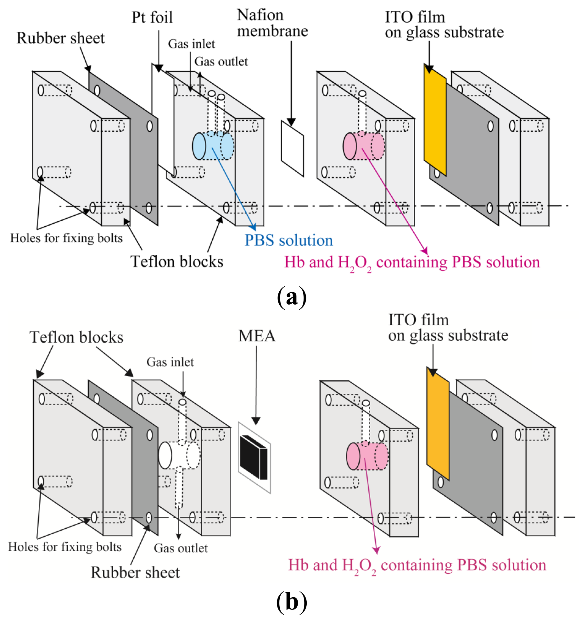
The single cells assembled in this study were composed of homemade accessories including two 10 mm in diameter cylindrical center-holed Teflon blocks, two Teflon blocks with flat surface, and rubber sheets (Viton®, DuPont, Wilmington, DE, USA). The performances for three types of the single cells will be shown in this study.
First type, named type I, was a most basic single cell as reported previously and shown in Figure 4a. A Pt foil and the ITO electrodes were used as the anode and the cathode, respectively. Nafion® 117 membrane (DuPont) was employed to maintain ion transport and prevent the penetration of Hb molecules to the anode. To purify and exchange with H+, the Nafion® membrane with 20 × 20 mm2 was soaked in 3% H2O2 solution and boiled for 1 h, then stored in dilute H2SO4 solution. The pretreated Nafion® membrane was soaked with water and placed between two Teflon blocks with 10 mm diameter of cylindrical center hole. After assembling of the single cell, the two cylindrical center holes were filled with PBS solution at the anode and 5 µM Hb and 1.8 mM H2O2 containing PBS solution at the cathode. H2 gas was produced in a water electrolysis cell and provided to the Pt foil electrode by the bubbling of the solution in the cylindrical hole at the anode.
Second and third types of single cells, named type II and III, employed a Pt dispersed carbon paper (1 mg cm−2 Pt loading, 20 wt% Pt/Vulcan XC72, ElectroChem, Inc., Woburn, MA, USA) as the anode. Membrane-electrode assembly (MEA) composed of one Nafion® membrane and one Pt dispersed carbon paper was prepared by a hot-press. The Nafion® 117 and the Pt dispersed carbon paper were cut into 20 × 20 mm2 and 15 × 15 mm2, respectively. The Nafion® membrane was pretreated as mentioned above. The Pt dispersed surface of the carbon paper was covered with 80 µL of 5 wt% Nafion® solution (Sigma-Aldrich, Inc., St. Louis, MO, USA), and pinched with Nafion® membrane between two Teflon blocks, then annealed in a dry oven for 30 min at 358 K and then for 10 min at 393 K. The prepared MEA was set on the single cell anode as shown in Figure 4b,c. H2 gas could be provided to the backside of the Pt dispersed carbon paper similarly to the polymer electrolyte fuel cells [41,42]. In the type II single cell, the ITO-coated glass plate was used as the cathode and the Hb and H2O2 containing PBS solution was used as the electrolyte. In the type III single cell, the ITO-coated porous glass was used as the cathode. The ITO-coated porous glass was dipped in 20 µM Hb solution for 0.5 h and rinsed with the PBS solution. The Hb adsorbed ITO porous glass was mounted in a leak-proof rubber sheet and placed on the Nafion® surface of the semi-MEA, as shown in Figure 4c. The solution phase in the cathode was relocated to the backside of the ITO-coated porous glass. The single cell performance was evaluated by slow rate current sweep techniques on a Solartron SI1287 Electrochemical Interface (Bognor Regis, West Sussex, UK).
4. Conclusions
We have demonstrated the performance of BFCs based on a DET between ITO electrodes and Hb molecules that exhibit an electrocatalytic activity for the reduction of H2O2 at the cathode. The OCV and maximum power density were observed 0.72 V and 3.1 µW cm−2, respectively, on the single cell using the ITO-coated glass plate. In this study, we successfully obtained a performance of 21.5 µW per single cell by increasing the specific surface area of the BFC cathode utilizing Hb-ITO systems.
Conflicts of Interest
The authors declare no conflict of interest.
References
- Leech, D.; Kavanagh, P.; Schuhmann, W. Enzymatic fuel cells: Recent progress. Electrochim. Acta 2012, 84, 223–234. [Google Scholar]
- Bullen, R.A.; Arnot, T.C.; Lakeman, J.B.; Walsh, F.C. Biofuel cells and their development. Biosens. Bioelectron. 2006, 21, 2015–2045. [Google Scholar]
- Halámková, L.; Halámek, J.; Bocharova, V.; Szczupak, A.; Alfonta, L.; Katz, E. Implanted biofuel cell operating in a living snail. J. Am. Chem. Soc. 2012, 134, 5040–5043. [Google Scholar]
- Zebda, A.; Renaud, L.; Cretin, M.; Innocent, C.; Pichot, F.; Ferrigno, R.; Tingry, S. Electrochemical performance of a glucose/oxygen microfluidic biofuel cell. J. Power Sources 2009, 193, 602–606. [Google Scholar]
- Nazaruk, E.; Smoliński, S.; Swatko-Ossor, M.; Ginalska, G.; Fiedurek, J.; Rogalski, J.; Bilewicz, R. Enzymatic biofuel cell based on electrodes modified with lipid liquid-crystalline cubic phases. J. Power Sources 2008, 183, 533–538. [Google Scholar]
- Togo, M.; Takamura, A.; Asai, T.; Kaji, H.; Nishizawa, M. Structural studies of enzyme-based microfluidic biofuel cell. J. Power Sources 2008, 178, 53–58. [Google Scholar]
- Horn, S.J.; Vaaje-Kolstad, G.; Westereng, B.; Eijsink, V.G.H. Novel enzymes for the degradation of cellulose. Biotechnol. Biofuels 2012, 5. [Google Scholar] [CrossRef]
- Drobov, R.; Kurth, D.G.; Möhwald, H.; Scheller, F.W.; Lisdat, F. Communication in a protein stack: Electron transfer between cytochrome c and bilirubin oxidase within a polyelectrolyte multilayer. Angew. Chem. Int. Ed. 2008, 47, 3000–3003. [Google Scholar]
- Brunel, L.; Denele, J.; Servat, K.; Kokoh, K.B.; Jolivalt, C.; Innocent, C.; Cretin, M.; Rolland, M.; Tingry, S. Oxygen transport through laccase biocathodes for a membrane-less glucose/O2 biofuel cell. Electrochem. Commun. 2007, 9, 331–336. [Google Scholar]
- Ikeda, T.; Kano, K. Bioelectrocatalysis-based application of quinoproteins and quinoprotein-containing bacterial cells in biosensors and biofuel cells. Biochim. Biophys. Acta Protein Proteomics 2003, 1647, 121–126. [Google Scholar]
- Tarasevich, M.R.; Bogdanovskaya, V.A.; Kapustin, A.V. Nanocomposite material laccase/dispersed carbon carrier for oxygen electrode. Electrochem. Commun 2003, 5, 491–496. [Google Scholar]
- Tsujimura, S.; Fujita, M.; Tatsumi, H.; Kano, K.; Ikeda, T. Bioelectrocatalysis-based dihydrogen/dioxygen fuel cell operating at physiological pH. Phys. Chem. Chem. Phys. 2001, 3, 1331–1335. [Google Scholar]
- Katz, E.; Willner, I.; Kotlyar, A.B. A non-compartmentalized glucose∣O2 biofuel cell by bioengineered electrode surfaces. J. Electroanal. Chem. 1999, 479, 64–68. [Google Scholar]
- Gorton, L.; Lindgren, A.; Larsson, T.; Munteanu, F.D.; Ruzgas, T.; Gazaryan, I. Direct electron transfer between heme-containing enzymes and electrodes as basis for third generation biosensors. Anal. Chim. Acta 1999, 400, 91–108. [Google Scholar]
- Palmore, G.T.R.; Bertschy, H.; Bergens, S.H.; Whitesides, G.M. A methanol/dioxygen biofuel cell that uses NAD+-dependent dehydrogenases as catalysts: Application of an electro-enzymatic method to regenerate nicotinamide adenine dinucleotide at low overpotentials. J. Electroanal. Chem. 1998, 443, 155–161. [Google Scholar]
- Fraaije, M.W.; Roubroeks, H.P.; Hagen, W.R.; van Berkel, W.J.H. Purification and characterization of an intracellular catalase-peroxidase from Penicillium Simplicissimum. Eur. J. Biochem. 1996, 235, 192–198. [Google Scholar]
- Prakash, P.A.; Yogeswaran, U.; Chen, S.-M. A review on direct electrochemistry of catalase for electrochemical sensors. Sensors 2009, 9, 1821–1844. [Google Scholar]
- Kamitaka, Y.; Tsujimura, S.; Kataoka, K.; Sakurai, T.; Ikeda, T.; Kano, K. Effects of axial ligand mutation of the type I copper site in bilirubin oxidase on direct electron transfer-type bioelectrocatalytic reduction of dioxygen. J. Electroanal. Chem. 2007, 601, 119–124. [Google Scholar]
- Bianco, P.; Haladjian, J.; Bourdillon, C.J. Immobilization of glucose oxidase on carbon electrodes. J. Electroanal. Chem. Interfacial Electrochem. 1990, 293, 151–163. [Google Scholar]
- Chen, C.-C.; Do, J.-S.; Gu, Y. Immobilization of HRP in mesoporous silica and its application for the construction of polyaniline modified hydrogen peroxide biosensor. Sensors 2009, 9, 4635–4648. [Google Scholar]
- Scheller, F.W.; Bistolas, N.; Liu, S.; Jänchen, M.; Katterle, M.; Wollenberger, U. Thirty years of haemoglobin electrochemistry. Adv. Colloid Interface Sci. 2005, 116, 111–120. [Google Scholar]
- Perutz, M.F.; Muirhead, H.; Cox, J.M.; Goaman, L.C.G.; Mathews, F.S.; McGandy, E.L.; Webb, L.E. Three-dimensional Fourier synthesis of horse oxyhaemoglobin at 2.8 Å resolution: (I) X-ray analysis. Nature 1968, 219, 29–32. [Google Scholar]
- Yin, F.; Shin, H.-K.; Kwon, Y.-S. Direct electrochemistry of hemoglobin immobilized on gold electrode by Langmuir–Blodgett technique. Biosens. Bioelectron. 2005, 21, 21–29. [Google Scholar]
- Revenga-Parra, M.; Lorenzo, E.; Pariente, F. Synthesis and electrocatalytic activity towards oxidation of hydrazine of a new family of hydroquinone salophen derivatives: Application to the construction of hydrazine sensors. Sens. Actuators B 2005, 107, 678–687. [Google Scholar]
- Topoglidis, E.; Astuti, Y.; Duriaux, F.; Grätzel, M.; Durrant, J.R. Direct electrochemistry and nitric oxide interaction of heme proteins adsorbed on nanocrystalline tin oxide electrodes. Langmuir 2003, 19, 6894–6900. [Google Scholar]
- Kawahara, N.Y.; Ohno, H. Thermal stability and electron transfer reaction of PEO-modified hemoglobin cast on an ITO electrode in polymer electrolytes. Electrochim. Acta 1998, 43, 1493–1497. [Google Scholar]
- Shan, D.; Han, E.; Xue, H.; Cosnier, S. Self-assembled films of hemoglobin/laponite/chitosan: Application for the direct electrochemistry and catalysis to hydrogen peroxide. Biomacromolecules 2007, 8, 3041–3046. [Google Scholar]
- Shi, G.; Sun, Z.; Liu, M.; Zhang, L.; Liu, Y.; Qu, Y.; Jin, L. Electrochemistry and electrocatalytic properties of hemoglobin in layer-by-layer films of SiO2 with vapor-surface sol-gel deposition. Anal. Chem. 2007, 79, 3581–3588. [Google Scholar]
- Zhao, G.; Xu, J.-J.; Chen, H.-Y. Fabrication, characterization of Fe3O4 multilayer film and its application in promoting direct electron transfer of hemoglobin. Electrochem. Commun. 2006, 8, 148–154. [Google Scholar]
- Feng, J.-J.; Xu, J.-J.; Chen, H.-Y. Direct electron transfer and electrocatalysis of hemoglobin adsorbed onto electrodeposited mesoporous tungsten oxide. Electrochem. Commun. 2006, 8, 77–82. [Google Scholar]
- Zhang, J.; Oyama, M. A hydrogen peroxide sensor based on the peroxidase activity of hemoglobin immobilized on gold nanoparticles-modified ITO electrode. Electrochim. Acta 2004, 50, 85–90. [Google Scholar]
- Jia, Y.; Wood, F.; Menu, P.; Faivre, B.; Caron, A.; Alayash, A.I. Oxygen binding and oxidation reactions of human hemoglobin conjugated to carboxylate dextran. Biochim. Biophys. Acta 2004, 1672, 164–173. [Google Scholar]
- Sun, H.; Hu, N. Voltammetric studies of hemoglobin-coated polystyrene latex bead films on pyrolytic graphite electrodes. Biophys. Chem. 2004, 110, 297–308. [Google Scholar]
- Gu, H.-Y.; Yu, A.-M.; Chen, H.-Y. Direct electron transfer and characterization of hemoglobin immobilized on a Au colloid–cysteamine-modified gold electrode. J. Electroanal. Chem. 2001, 516, 119–126. [Google Scholar]
- Ayato, Y.; Takatsu, A.; Kato, K.; Matsuda, N. Direct electrochemistry of hemoglobin molecules adsorbed on bare indium tin oxide electrode surfaces. Jpn. J. Appl. Phys. 2008, 47, 1333–1336. [Google Scholar]
- Ayato, Y.; Itahashi, T.; Matsuda, N. Direct electron transfer of hemoglobin molecules on bare ITO electrodes. Chem. Lett. 2007, 36, 406–407. [Google Scholar]
- Ayato, Y.; Yamagiwa, K.; Shiroishi, H.; Kuwano, J. Direct electron transfer and electrocatalysis of hemoglobin on ITO nanoparticle electrodes. ECS Trans. 2013, 50, 1–10. [Google Scholar]
- Ayato, Y.; Matsuda, N. A novel biofuel cell based on direct electron transfer utilizing enzymatic activity of hemoglobin at indium-tin-oxide electrodes in cathodic process. Chem. Lett. 2009, 38, 504–505. [Google Scholar]
- Sawada, Y.; Kobayashi, C.; Seki, S.; Funakubo, H. Highly-conducting indium-tin-oxide transparent films fabricated by spray CVD using ethanol solution of indium (III) chloride and tin (II) chloride. Thin Solid Films 2002, 409, 46–50. [Google Scholar]
- Kobayashi, H.; Ishida, T.; Nakato, Y.; Tsubomura, H. Mechanism of carrier transport in highly efficient solar cells having indium tin oxide/Si junctions. J. Appl. Phys. 1991, 69, 1736–1743. [Google Scholar]
- Ayato, Y.; Kunimatsu, K.; Osawa, M.; Okada, T. Study of Pt electrode/Nafion ionomer interface in HClO4 by in situ surface-enhanced FTIR spectroscopy. J. Electrochem. Soc. 2006, 153, A203–A209. [Google Scholar]
- Ayato, Y.; Okada, T.; Yamazaki, Y. Characterization of bipolar ion exchange membrane for polymer electrolyte fuel cells. Electrochemistry 2003, 71, 313–317. [Google Scholar]


© 2013 by the authors; licensee MDPI, Basel, Switzerland. This article is an open access article distributed under the terms and conditions of the Creative Commons Attribution license( http://creativecommons.org/licenses/by/3.0/).
Share and Cite
Ayato, Y.; Matsuda, N. Evaluation of Biofuel Cells with Hemoglobin as Cathodic Electrocatalysts for Hydrogen Peroxide Reduction on Bare Indium-Tin-Oxide Electrodes. Energies 2014, 7, 1-12. https://0-doi-org.brum.beds.ac.uk/10.3390/en7010001
Ayato Y, Matsuda N. Evaluation of Biofuel Cells with Hemoglobin as Cathodic Electrocatalysts for Hydrogen Peroxide Reduction on Bare Indium-Tin-Oxide Electrodes. Energies. 2014; 7(1):1-12. https://0-doi-org.brum.beds.ac.uk/10.3390/en7010001
Chicago/Turabian StyleAyato, Yusuke, and Naoki Matsuda. 2014. "Evaluation of Biofuel Cells with Hemoglobin as Cathodic Electrocatalysts for Hydrogen Peroxide Reduction on Bare Indium-Tin-Oxide Electrodes" Energies 7, no. 1: 1-12. https://0-doi-org.brum.beds.ac.uk/10.3390/en7010001