New Insights in the Long-Term Atmospheric Corrosion Mechanisms of Low Alloy Steel Reinforcements of Cultural Heritage Buildings

Abstract
:
1. Introduction
2. Materials and Methods
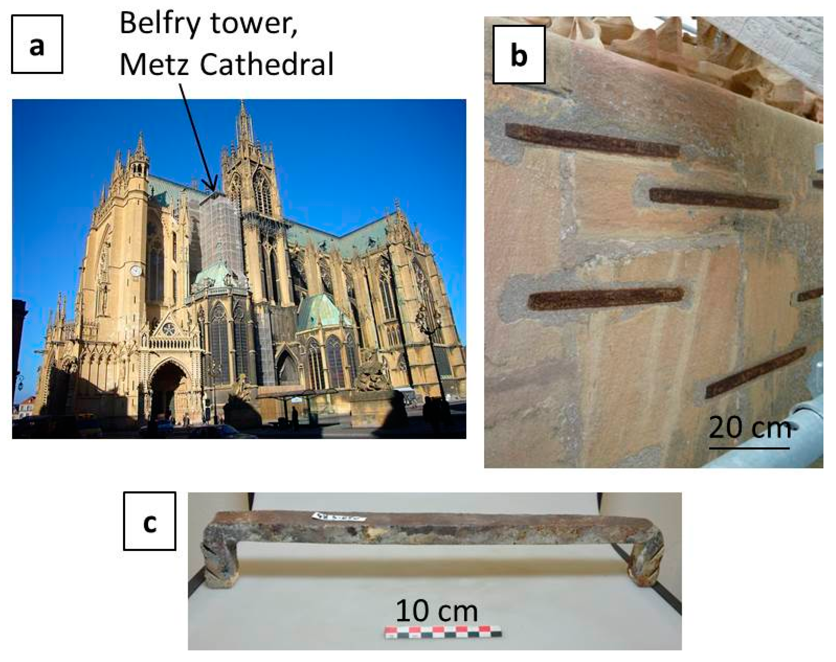
2.1. Set of Samples
2.2. Characterisation Methods
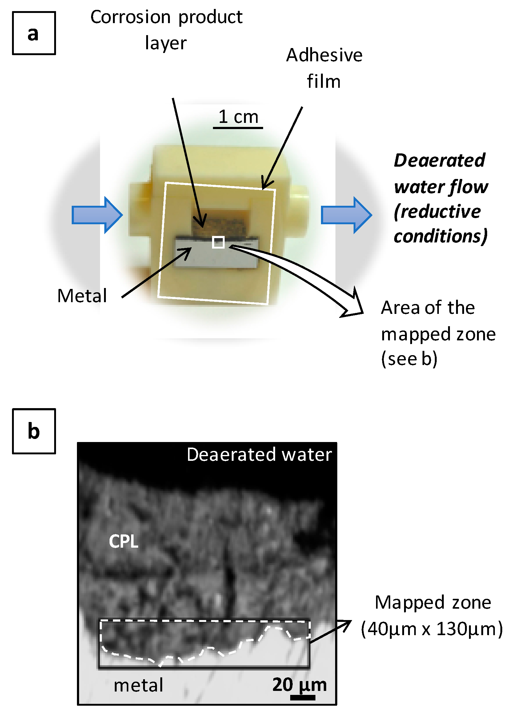
2.3. In Situ Experimental Setup
3. Results
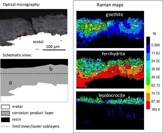
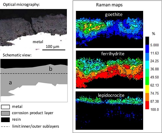
3.1. Characterisation of the Corrosion Products
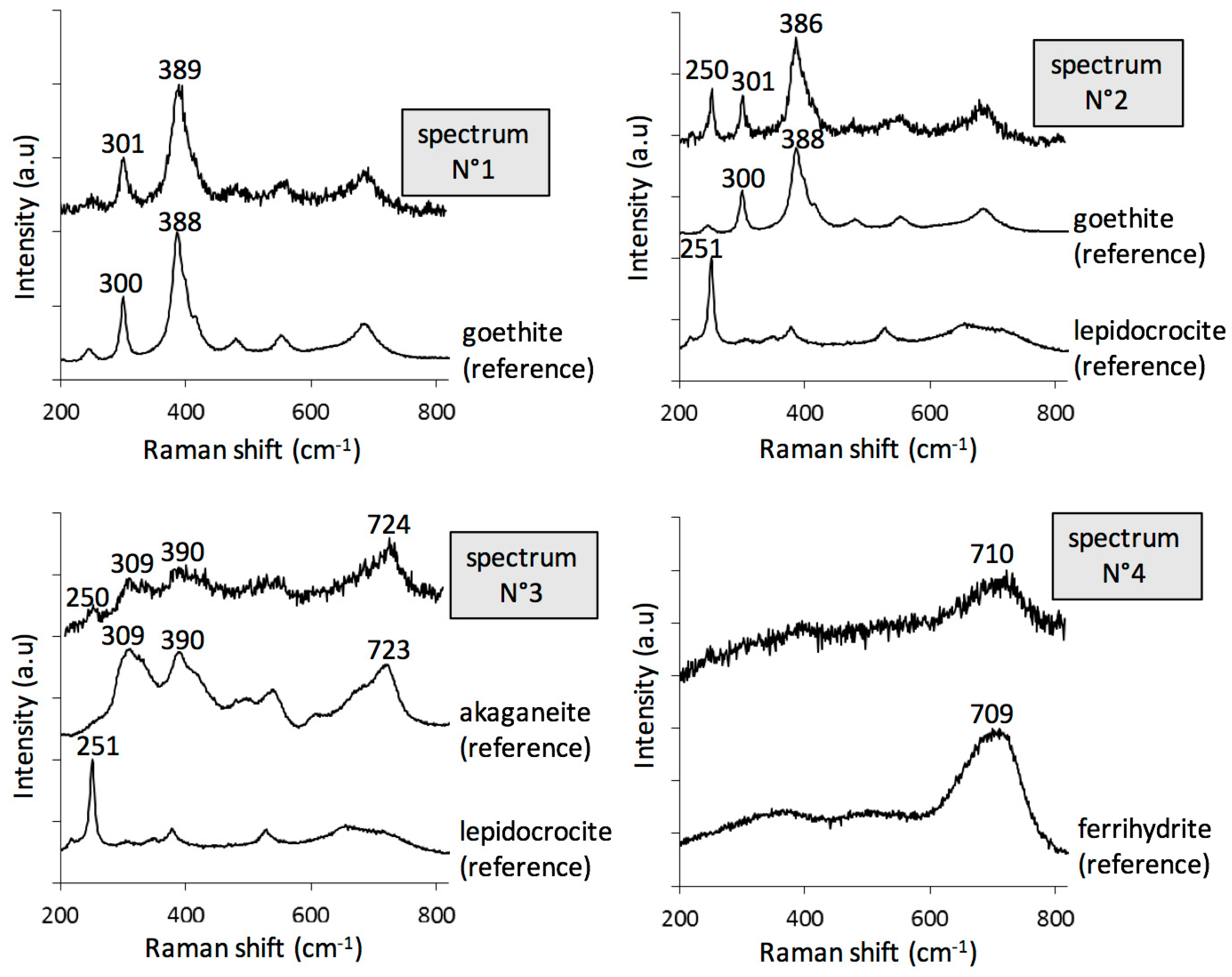
- goethite α-FeOOH (bands at 300 and 390 cm−1, spectra N° 1–2);
- lepidocrocite γ-FeOOH (intense peak at 250 cm−1, spectrum N° 2);
- akaganeite β-FeO1-x(OH)1+x,Clx) (combination of asymmetric bands at 309, 390, and 724 cm−1, spectrum N° 3), only present in rare zones;
- ferrihydrite Fe2O3,1.8H2O [31], and more generally hydrated oxyhydroxides (broad and symmetric signal, without shoulder, around 710 cm−1, spectrum N° 4). In fact, feroxyhite (δ-FeOOH) also presents a broad band in the same region as ferrihydrite, but at 677 cm−1 [32]. The Raman spectra obtained on the Metz cathedral samples are mainly in agreement with ferrihydrite, but the presence of small amounts of feroxyhite cannot be completely excluded.
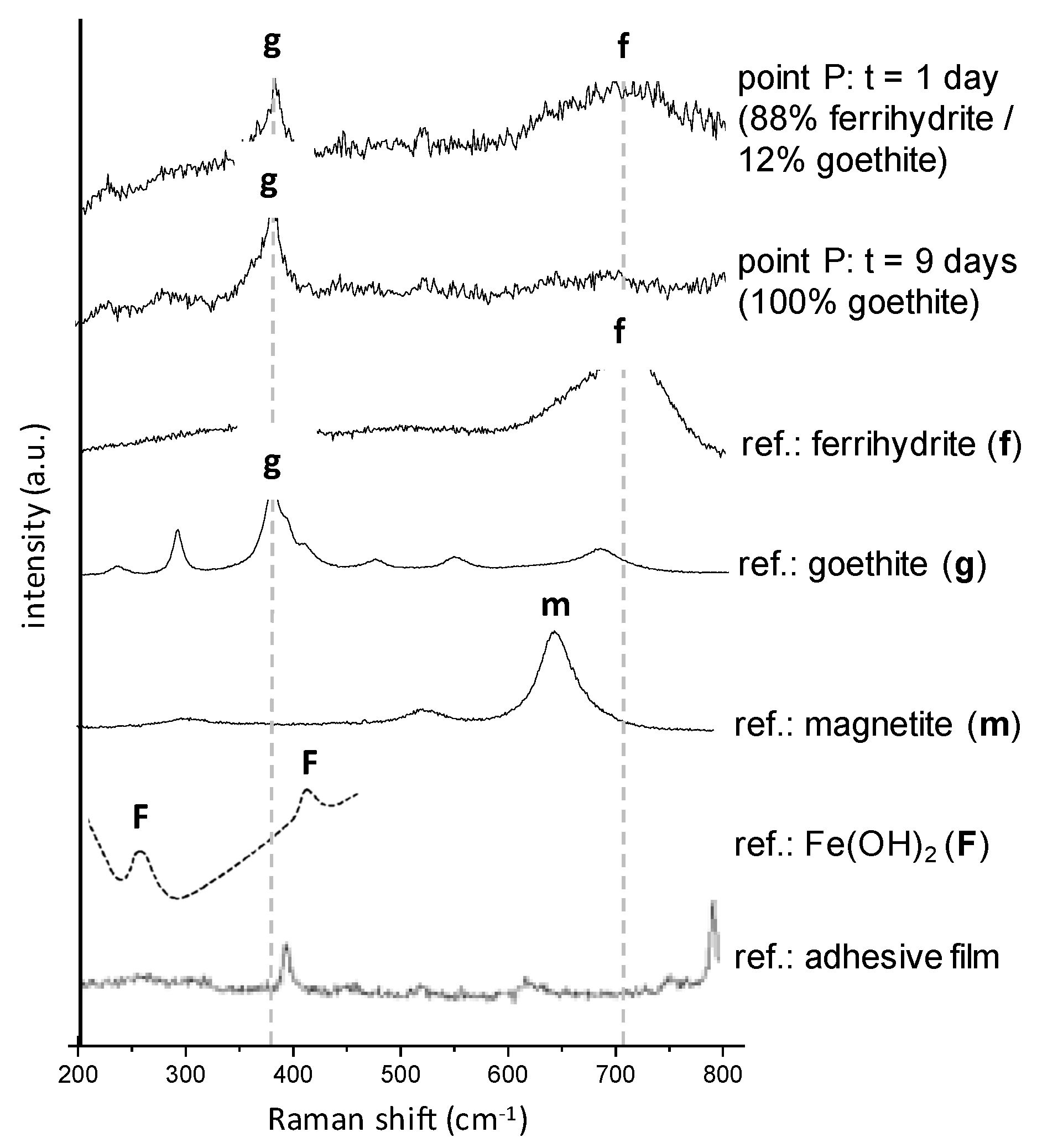
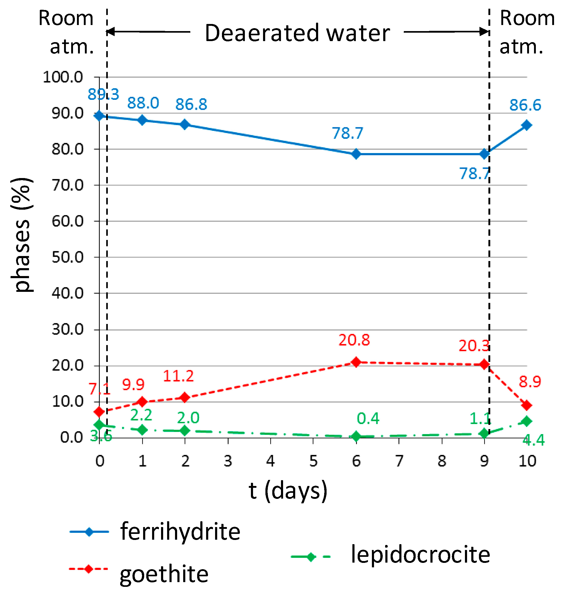
3.2. In Situ Reactivity Test of the Corrosion Layer
4. Discussion
5. Conclusions
Supplementary Materials
Acknowledgments
Author Contributions
Conflicts of Interest
References
- Disser, A.; Dillmann, P.; Leroy, M.; L’Héritier, M.; Bauvais, S.; Fluzin, P. Iron supply for the building of Metz cathedral: New methodological development for provenance studies and historical considerations. Archaeometry 2016, 59, 493–510. [Google Scholar] [CrossRef]
- Leroy, S.; L’Héritier, M.; Delqué-Kolic, E.; Dumoulin, J.-P.; Moreau, C.; Dillmann, P. Consolidation or initial design? Radiocarbon dating of ancient iron alloys sheds light on the reinforcements of French Gothic Cathedrals. J. Archaeol. Sci. 2015, 53, 190–201. [Google Scholar] [CrossRef]
- Disser, A.; Dillmann, P.; Bourgain, C.; L’Héritier, M.; Vega, E.; Bauvais, S.; Leroy, M. Iron reinforcements in Beauvais and Metz Cathedrals: From bloomery or finery? The use of logistic regression for differentiating smelting processes. J. Archaeol. Sci. 2014, 42, 315–333. [Google Scholar] [CrossRef]
- L’Heritier, M.; Dillmann, P.; Aumard, S.; Fluzin, P. Iron? Wich iron? Methodologies for metallographic and slag inclusion studies applied to ferrous reinforcements from Auxerre Cathedral. In The World of Iron; Humphris, J., Rehren, T., Eds.; Archetype Publications: London, UK, 2013; pp. 409–420. [Google Scholar]
- Leygraf, C.; Graedel, T.E. Atmospheric Corrosion; John Wiley & Sons: New York, NY, USA, 2000; p. 354. [Google Scholar]
- Dillmann, P.; Neff, D.; Féron, D. Archaeological analogues and corrosion prediction: From past to future. A review. Corros. Eng. Sci. Technol. 2014, 49, 567–576. [Google Scholar] [CrossRef]
- Feron, D.; Crusset, D.; Gras, J.M. Corrosion Issues in the French High-Level Nuclear Waste Program (Reprinted from Proceedings of the CORROSION/2008 Research Topical Symposium). Corrosion 2009, 65, 213–223. [Google Scholar] [CrossRef]
- Dillmann, P.; Mazaudier, F.; Hoerle, S. Advances in understanding atmospheric corrosion of iron I—Rust characterisation of ancient ferrous artefacts exposed to indoor atmospheric corrosion. Corros. Sci. 2004, 46, 1401–1429. [Google Scholar] [CrossRef]
- Monnier, J.; Bellot-Gurlet, L.; Baron, D.; Neff, D.; Guillot, I.; Dillmann, P. A methodology for Raman structural quantification imaging and its application to iron indoor atmospheric corrosion products. J. Raman Spectrosc. 2011, 42, 773–781. [Google Scholar] [CrossRef]
- Monnier, J.; Neff, D.; Reguer, S.; Dillmann, P.; Bellot-Gurlet, L.; Leroy, E.; Foy, E.; Legrand, L.; Guillot, I. A corrosion study of the ferrous medieval reinforcement of the Amiens cathedral. Phase characterisation and localisation by various microprobes techniques. Corros. Sci. 2010, 52, 695–710. [Google Scholar] [CrossRef]
- Bouchar, M.; Foy, E.; Neff, D.; Dillmann, P. The complex corrosion system of a medieval iron rebar from the Bourges’ Cathedral. Characterization and reactivity studies. Corros. Sci. 2013, 76, 361–372. [Google Scholar] [CrossRef]
- Suzuki, I.; Masuko, N.; Hisamatsu, Y. Electrochemical properties of iron rust. Corros. Sci. 1979, 19, 521–535. [Google Scholar] [CrossRef]
- Evans, U.R. Electrochemical Mechanism of Atmospheric Rusting. Nature 1965, 206, 980–982. [Google Scholar] [CrossRef]
- Matsushima, I.; Ueno, T. On the protective nature of atmospheric rust on low-alloy steel. Corros. Sci. 1971, 11, 129–140. [Google Scholar] [CrossRef]
- Stratmann, M. The atmospheric corrosion of iron—A discussion of the physico-chemical fundamentals of this omnipresent corrosion process. Invited Review. Ber. Bunsenges. Phys. Chem. 1990, 94, 626–639. [Google Scholar] [CrossRef]
- Strattmann, M.; Streckel, H. On the atmospheric corrosion of metals which are covered with thin electrolyte layers-I. verification of the experimental technique. Corros. Sci. 1990, 30, 681–696. [Google Scholar] [CrossRef]
- Strattmann, M.; Streckel, H.; Kim, K.T.; Crockett, S. On the atmospheric corrosion of metals which are covered with thin electrolyte layers-III. The measurment of polaristaion curves on metal surfaces which are covered by thin electrolyte layers. Corros. Sci. 1990, 30, 715–734. [Google Scholar] [CrossRef]
- Lair, V.; Antony, H.; Legrand, L.; Chausse, A. Electrochemical reduction of ferric corrosion products and evaluation of galvanic coupling with iron. Corros. Sci. 2006, 48, 2050–2063. [Google Scholar] [CrossRef]
- Antony, H.; Legrand, L.; Peulon, S.; Lair, V.; Chaussé, A. Applications of Thin Layers of Iron Oxidation Products for Corrosion Studies; Eurocorr: Nice, France, 2004; CD ROM. [Google Scholar]
- Antony, H.; Legrand, L.; Maréchal, L.; Perrin, S.; Dillmann, P.; Chaussé, A. Study of lepidocrocite electrochemical reduction in neutral and slightly alkaline solutions at 25 °C. Electrochim. Acta 2005, 51, 745–753. [Google Scholar] [CrossRef]
- Monnier, J.; Reguer, S.; Foy, E.; Testemale, D.; Mirambet, F.; Saheb, M.; Dillmann, P.; Guillot, I. XAS and XRD in situ characterisation of reduction and reoxidation processes of iron corrosion products involved in atmospheric corrosion. Corros. Sci. 2014, 78, 293–303. [Google Scholar] [CrossRef]
- Stratmann, M.; Bohnenkamp, K.; Engell, H.-J. An electrochemical study of phase-transitions in rust layers. Corros. Sci. 1983, 23, 969–985. [Google Scholar] [CrossRef]
- Stratmann, M.; Hoffmann, K. In Situ Mössbauer spectroscopic study of reactions within rust layers. Corros. Sci. 1989, 29, 1329–1352. [Google Scholar] [CrossRef]
- Neff, D.; Bellot-Gurlet, L.; Dillmann, P.; Reguer, S.; Legrand, L. Raman imaging of ancient rust scales on archaeological iron artefacts for long-term atmospheric corrosion mechanisms study. J. Raman Spectrosc. 2006, 37, 1228–1237. [Google Scholar] [CrossRef]
- Burger, E.; Monnier, J.; Berger, P.; Neff, D.; L’Hostis, V.; Perrin, S.; Dillmann, P. The long-term corrosion of mild steel in depassivated concrete: Localizing the oxygen reduction sites in corrosion products by isotopic tracer method. J. Mater. Res. 2011, 26, 3107–3115. [Google Scholar] [CrossRef]
- Monnier, J.; Burger, E.; Berger, P.; Neff, D.; Guillot, I.; Dillmann, P. Localisation of oxygen reduction sites in the case of iron long term atmospheric corrosion. Corros. Sci. 2011, 53, 2468–2473. [Google Scholar] [CrossRef]
- Almeida, E.; Morcillo, M.; Rosales, B.; Marrocos, M. Atmospheric corrosion of mild steel. Part I—Rural and urban atmospheres. Mater. Corros. 2000, 51, 859–864. [Google Scholar] [CrossRef]
- Graedel, T.E.; Frankenthal, R.P. Corrosion Mechanism for Iron and Low Alloy Steels Exposed to the Atmosphere. J. Electrochem. Soc. 1990, 137, 2385–2394. [Google Scholar] [CrossRef]
- Tidblad, J. Atmospheric corrosion of heritage metallic artefacts: Processes and prevention. In Corrosion and Conservation of Cultural Heritage Metallic Artefacts; Woodhead Publishing: Oxford, UK, 2013; pp. 37–52. [Google Scholar]
- Shahack-Gross, R.; Berna, F.; Karkanas, P.; Weiner, S. Bat guano and preservation of archaeological remains in cave sites. J. Archaeol. Sci. 2004, 31, 1259–1272. [Google Scholar] [CrossRef]
- Schwertmann, U.; Cornell, R.M. Iron Oxides in the Laboratory; Wiley-VCH: Weinheim, Germany, 2000; p. 137. [Google Scholar]
- Neff, D.; Reguer, S.; Bellot-Gurlet, L.; Dillmann, P.; Bertholon, R. Structural characterization of corrosion products on archaeological iron. An integrated analytical approach to establish corrosion forms. J. Raman Spectrosc. 2004, 35, 739–745. [Google Scholar] [CrossRef]
- Monnier, J.; Réguer, S.; Vantelon, D.; Dillmann, P.; Neff, D.; Guillot, I. X-rays absorption study on medieval corrosion layers for the understanding of very long-term indoor atmospheric iron corrosion. Appl. Phys. A Mater. Sci. Process. 2010, 99, 399–406. [Google Scholar] [CrossRef]
- Balasubramaniam, R.; Kumar, A.V.R.; Dillmann, P. Characterization of rust on ancient indian iron. Curr. Sci. 2003, 85, 101–110. [Google Scholar]
- Lutz, H.D.; Möller, H.; Schmidt, M. Lattice vibration spectra. Part LXXXII. Brucite-type hydroxides M(OH)2 (M = Ca, Mn, Co, Fe, Cd)—IR and Raman spectra, neutron diffraction of Fe(OH)2. J. Mol. Struct. 1994, 328, 121–132. [Google Scholar] [CrossRef]
- Provent, E. Etude de la Corrosion Atmosphérique et dans la Pierre des Armatures Métalliques du 18ème siècle de la Cathédrale d’Orléans; LAPA/CEA; CEA Saclay: Gif Sur Yvette, France, 2010. [Google Scholar]
- Keiser, J.T.; Brown, C.W.; Heidersbach, R.H. Characterization of the passive film formed on weathering steels. Corros. Sci. 1983, 23, 251–259. [Google Scholar] [CrossRef]
- Kashima, K.; Hara, S.; Kishikawa, H.; Miyuki, H. Evaluation of protective ability of rust layers on weathering steels by potential measurment. Corros. Eng. 2000, 49, 25–37. [Google Scholar] [CrossRef]
- Burger, E.; Fénart, M.; Perrin, S.; Neff, D.; Dillmann, P. Use of the gold markers method to predict the mechanisms of iron atmospheric corrosion. Corros. Sci. 2011, 53, 2122–2130. [Google Scholar] [CrossRef]
- Seinfeld, J.H.; Pandis, S.N.; Noone, K. Atmospheric Chemistry and Physics: From Air Pollution to Climate Change; AIP: University Park, MD, USA, 1998. [Google Scholar]
- Monnier, J.; Vantelon, D.; Reguer, S.; Dillmann, P. X-ray absorption spectroscopy study of the various forms of phosphorus in ancient iron samples. J. Anal. At. Spectrom. 2011, 26, 885–891. [Google Scholar] [CrossRef]
- Morcillo, M.; Chico, B.; Díaz, I.; Cano, H.; de la Fuente, D. Atmospheric corrosion data of weathering steels. A review. Corros. Sci. 2013, 77, 6–24. [Google Scholar] [CrossRef]
- Yamashita, M.; Miyuki, H.; Matsuda, Y.; Nagano, H.; Misawa, T. The long term growth of the protective rust layer formed on weathering steel by atmospheric corrosion during a quarter of a century. Corros. Sci. 1994, 36, 283–299. [Google Scholar] [CrossRef]
- Misawa, T.; Hashimoto, K.; Shimodaira, S. The mecanism of formation of iron oxide and oxyhydroxides in aquaeous solutions at room temperature. Corros. Sci. 1974, 14, 131–149. [Google Scholar] [CrossRef]
- Misawa, T.; Kyuno, T.; Suetaka, W.; Shimodai, S. Mechanism of atmospheric rusting and effect of Cu and P on rust formation of low alloyed steels. Corros. Sci. 1971, 11, 35–48. [Google Scholar] [CrossRef]
- Arai, Y.; Sparks, D.L. ATR–FTIR Spectroscopic Investigation on Phosphate Adsorption Mechanisms at the Ferrihydrite–Water Interface. J. Colloid Interface Sci. 2001, 241, 317–326. [Google Scholar] [CrossRef]
- Torrent, J.; Barron, V.; Schwertmann, U. Phosphate adsorption and desorption by goethites differing in crystal morphology. Soil Sci. Soc. Am. J. 1990, 54, 1007–1012. [Google Scholar] [CrossRef]
- Cornell, R.; Schwertmann, U. The Iron Oxides—Structure, Properties, Occurrences and Uses, 2nd ed.; Wiley-VCH Verlag: Weinheim, Germany, 2003; p. 664. [Google Scholar]
- Fox, L.E. The solubility of colloidal ferric hydroxide and its relevance to iron concentrations in river water. Geochim. Cosmochim. Acta 1988, 52, 771–777. [Google Scholar] [CrossRef]
- Postma, D. The reactivity of iron oxides in sediments: A kinetic approach. Geochim. Cosmochim. Acta 1993, 57, 5027–5034. [Google Scholar] [CrossRef]
- Antony, H.; Perrin, S.; Dillmann, P.; Legrand, L.; Chaussé, A. Electrochemical study of indoor atmospheric corrosion layers formed on ancient iron artefacts. Electrochim. Acta 2007, 52, 7754–7759. [Google Scholar] [CrossRef]


| Average % | ||||
|---|---|---|---|---|
| Ferrihydrite | Goethite | Lepidocrocite | Akaganeite | |
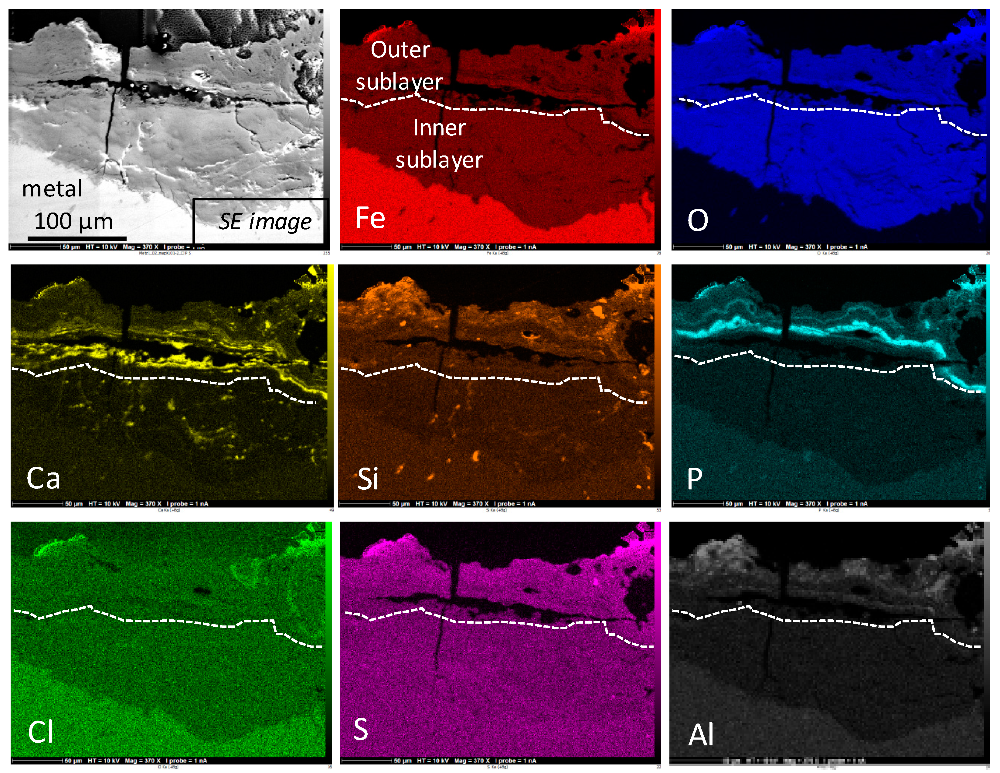
| Inner sublayer (zone a) | 77 | 20 | 3 | <1 |
| Outer sublayer (zone b) | 44 | 21 | 35 | n.d. |
| Layer Part | Morphology | Minor Elements | Phases % |
|---|---|---|---|
| Inner | Cracks (micro and sub-micro) Multiphased Relatively dense | Ca (exogenous) along cracks (up to 10%) Si (endogenous) from former slag inclusions P (endogenous) from the metal (about 0.5%) | Ferrihydrite: 77 Goethite: 20 Lepidocrocite: 3 |
| Outer | Cracks (micro and sub-micro) Porous | Ca (exogenous) along cracks (up to 10%) Si (exogenous) Cl (exogenous) in rare zones S (exogenous) along outer surface P (exogenous) up to 10% | Ferrihydrite: 44 Goethite: 21 Lepidocrocite: 35 |
© 2017 by the authors. Licensee MDPI, Basel, Switzerland. This article is an open access article distributed under the terms and conditions of the Creative Commons Attribution (CC BY) license (http://creativecommons.org/licenses/by/4.0/).
Share and Cite
Bouchar, M.; Dillmann, P.; Neff, D. New Insights in the Long-Term Atmospheric Corrosion Mechanisms of Low Alloy Steel Reinforcements of Cultural Heritage Buildings. Materials 2017, 10, 670. https://0-doi-org.brum.beds.ac.uk/10.3390/ma10060670
Bouchar M, Dillmann P, Neff D. New Insights in the Long-Term Atmospheric Corrosion Mechanisms of Low Alloy Steel Reinforcements of Cultural Heritage Buildings. Materials. 2017; 10(6):670. https://0-doi-org.brum.beds.ac.uk/10.3390/ma10060670
Chicago/Turabian StyleBouchar, Marie, Philippe Dillmann, and Delphine Neff. 2017. "New Insights in the Long-Term Atmospheric Corrosion Mechanisms of Low Alloy Steel Reinforcements of Cultural Heritage Buildings" Materials 10, no. 6: 670. https://0-doi-org.brum.beds.ac.uk/10.3390/ma10060670