Material Characterization of a Magnetorheological Fluid Subjected to Long-Term Operation in Damper

 , , , ,
  , and
, and
Abstract
:1. Introduction
2. Experimental Setup
2.1. MR Fluid
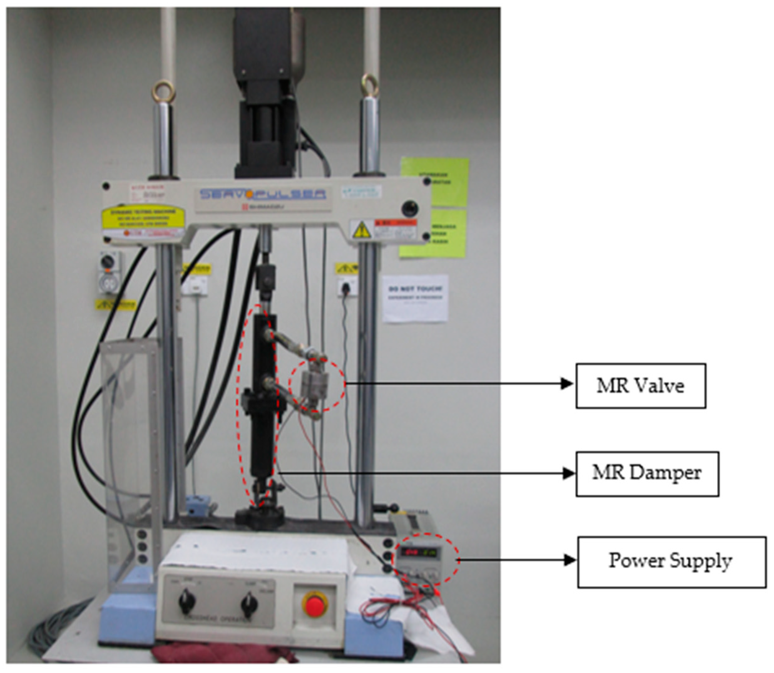
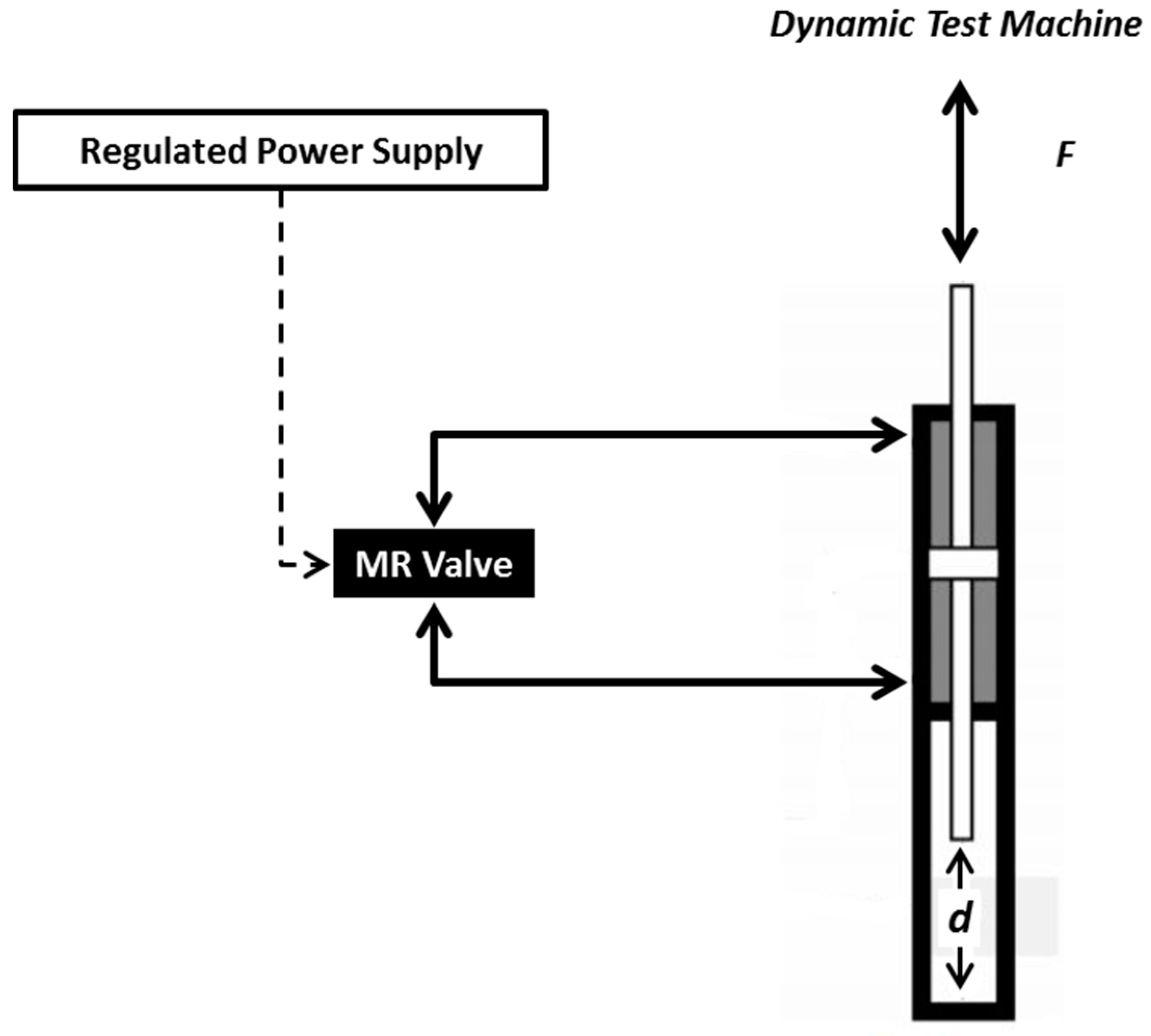
2.2. MR Damper and Testing Machine
2.3. Sample Characterization
2.4. Experimental Procedures
3. Results and Discussion
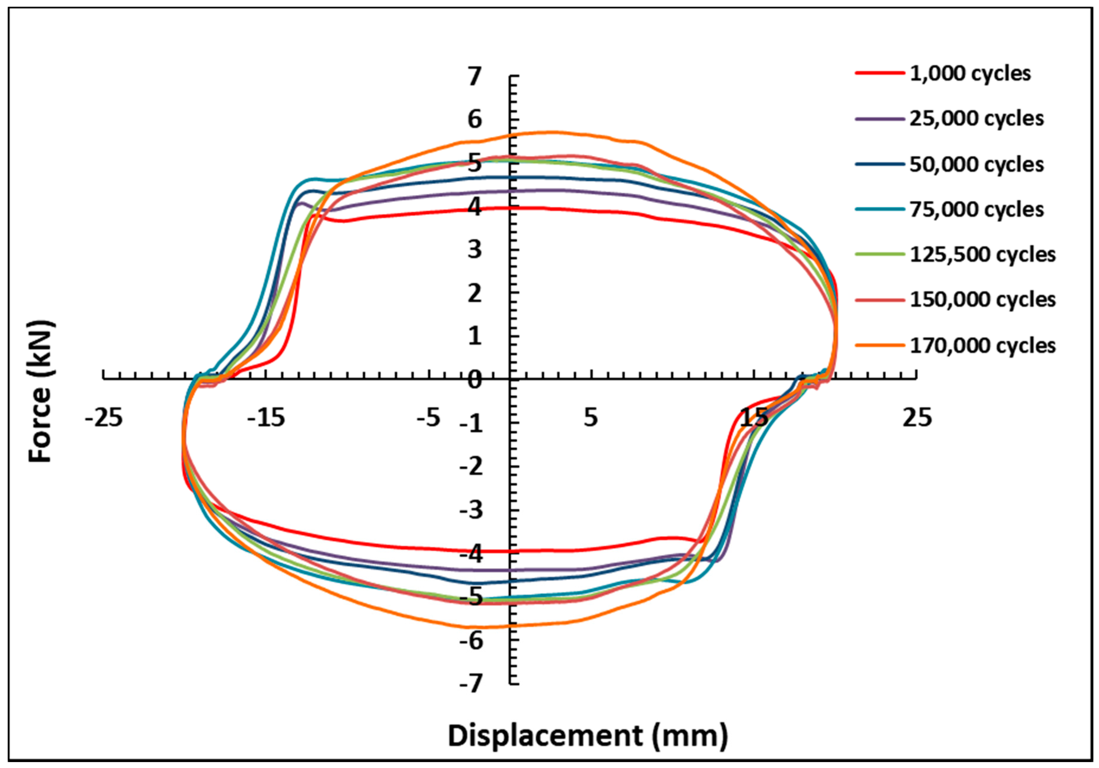
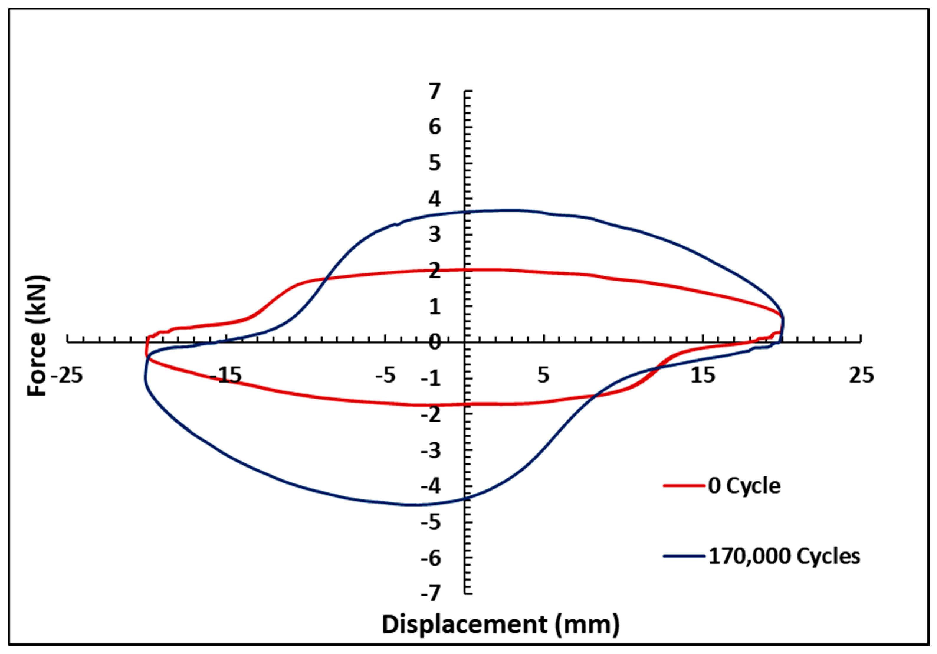
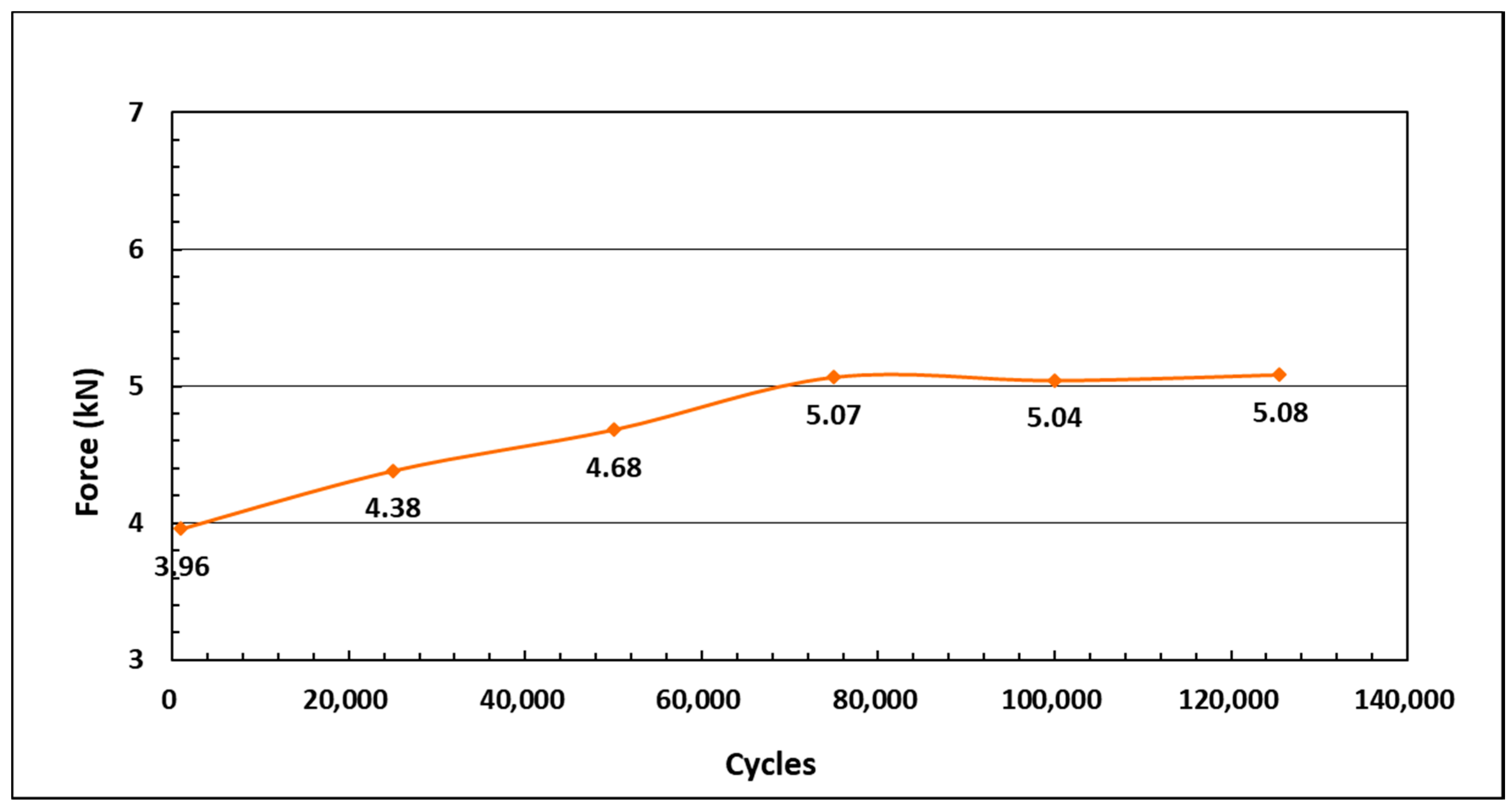
3.1. Long-Term Exposure
3.2. In Use Thickening (IUT)
3.3. Surface Roughness
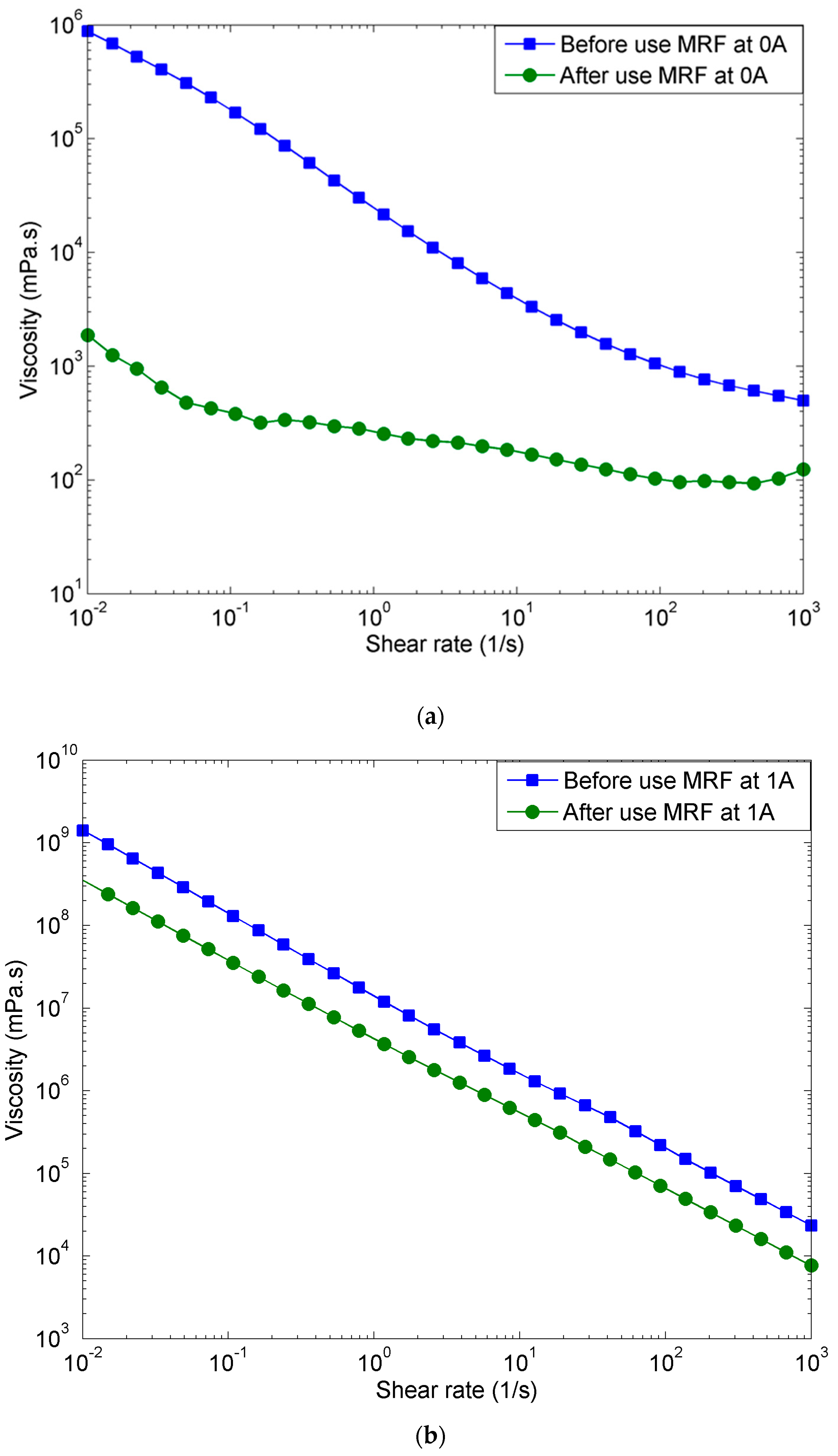
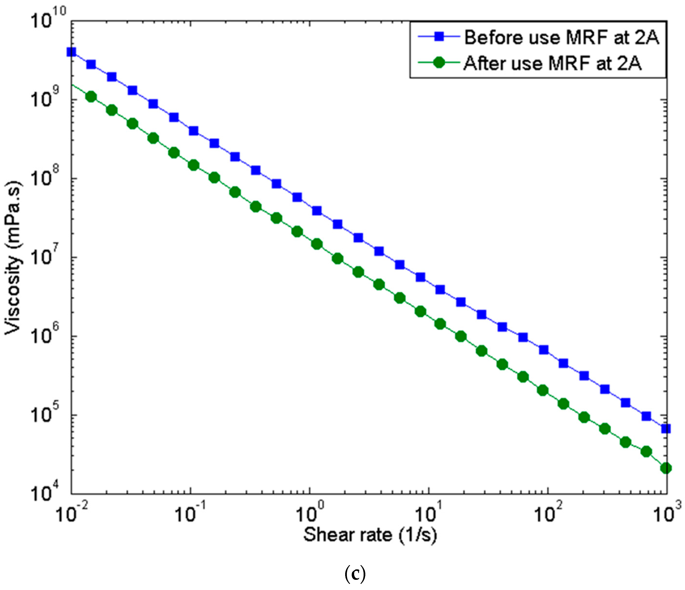
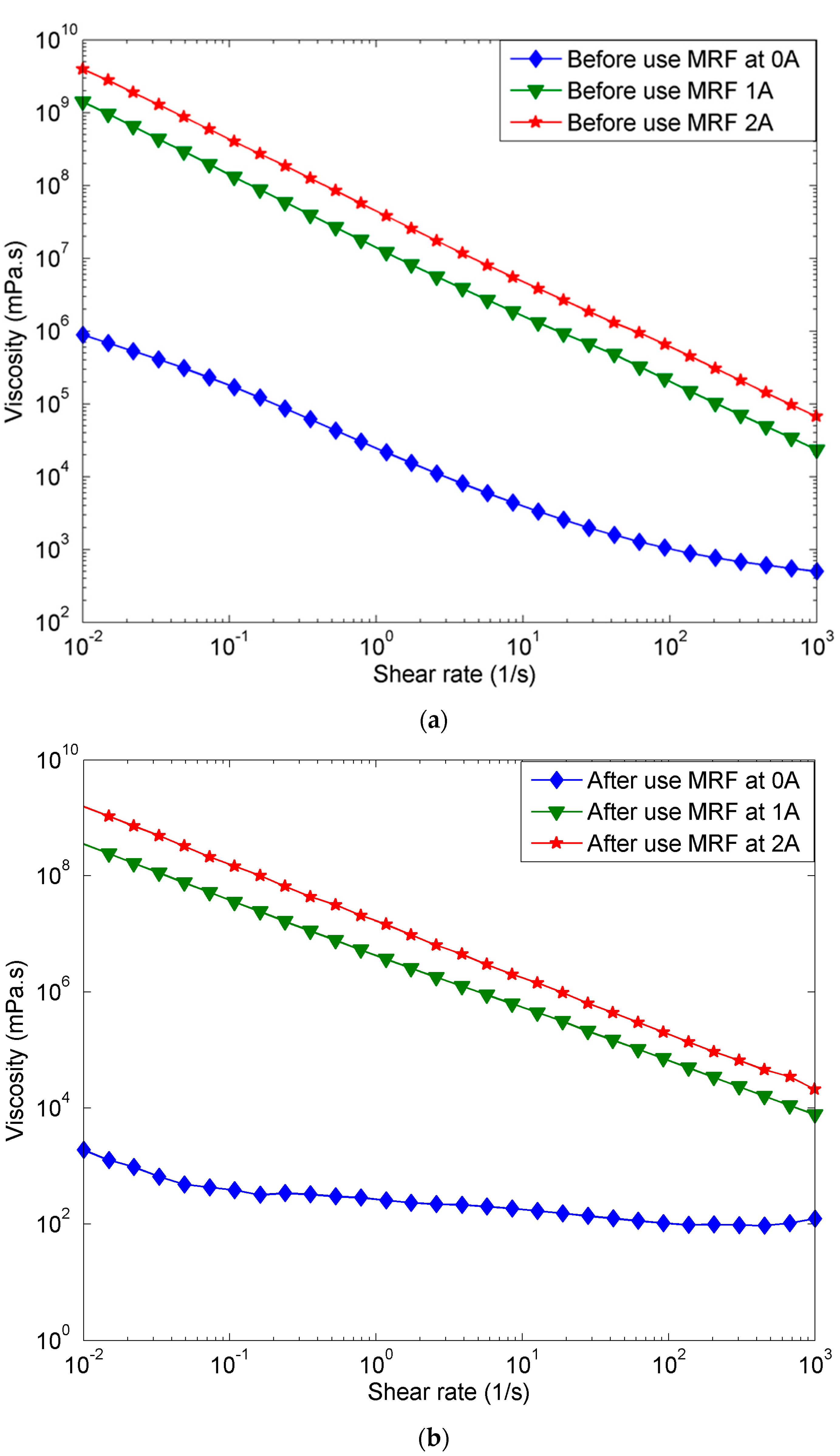
3.4. Rheological Properties
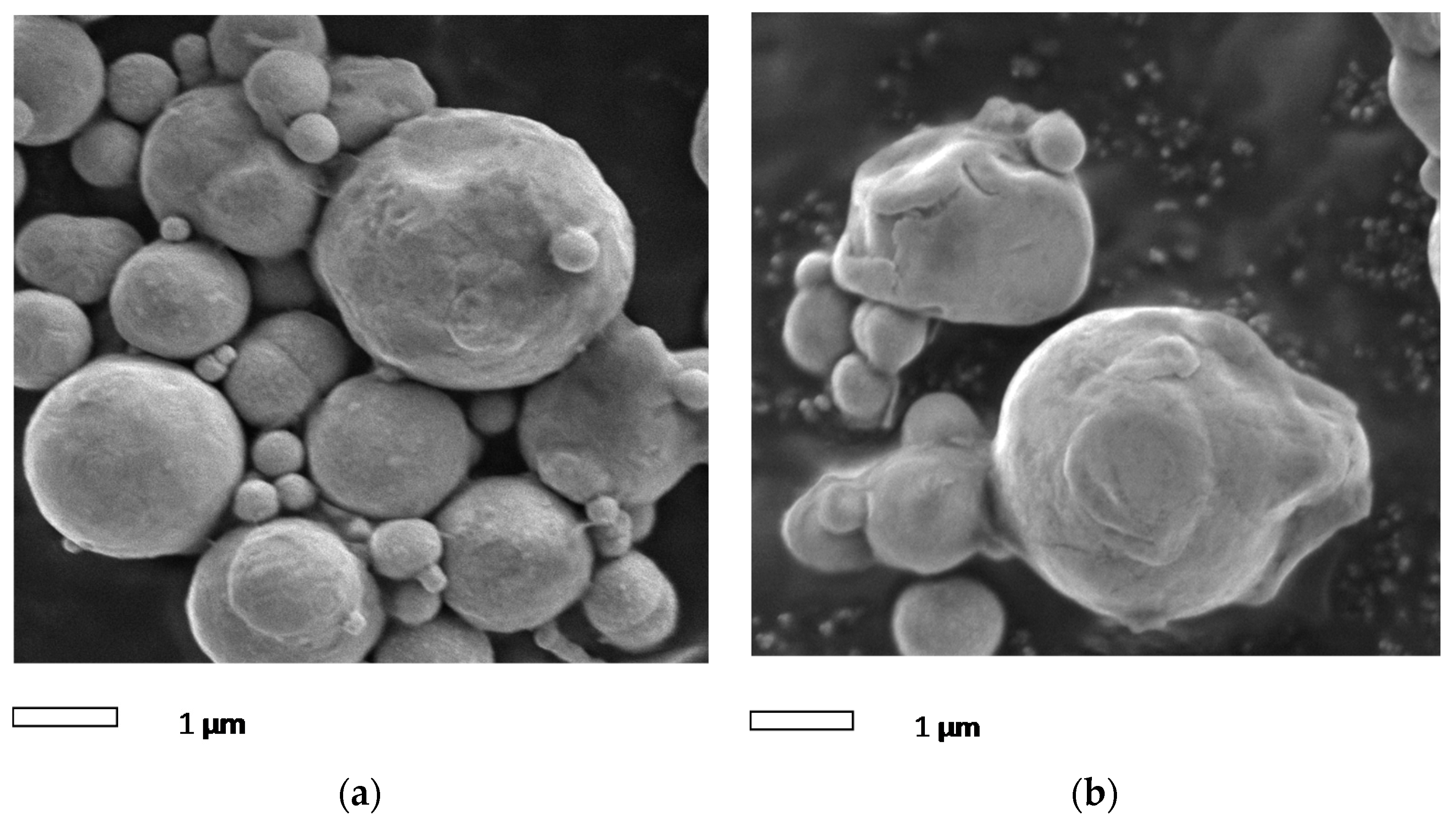
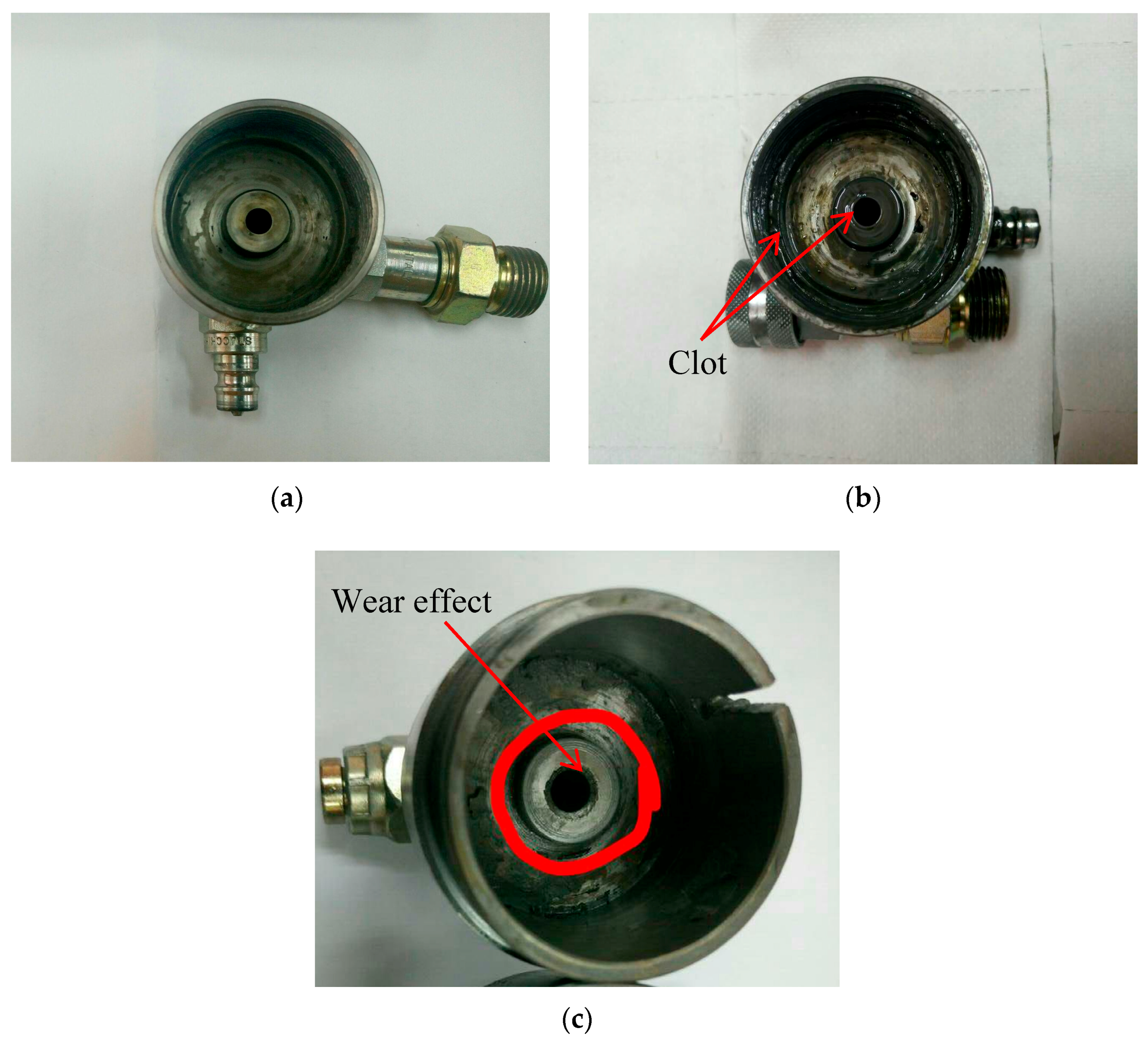
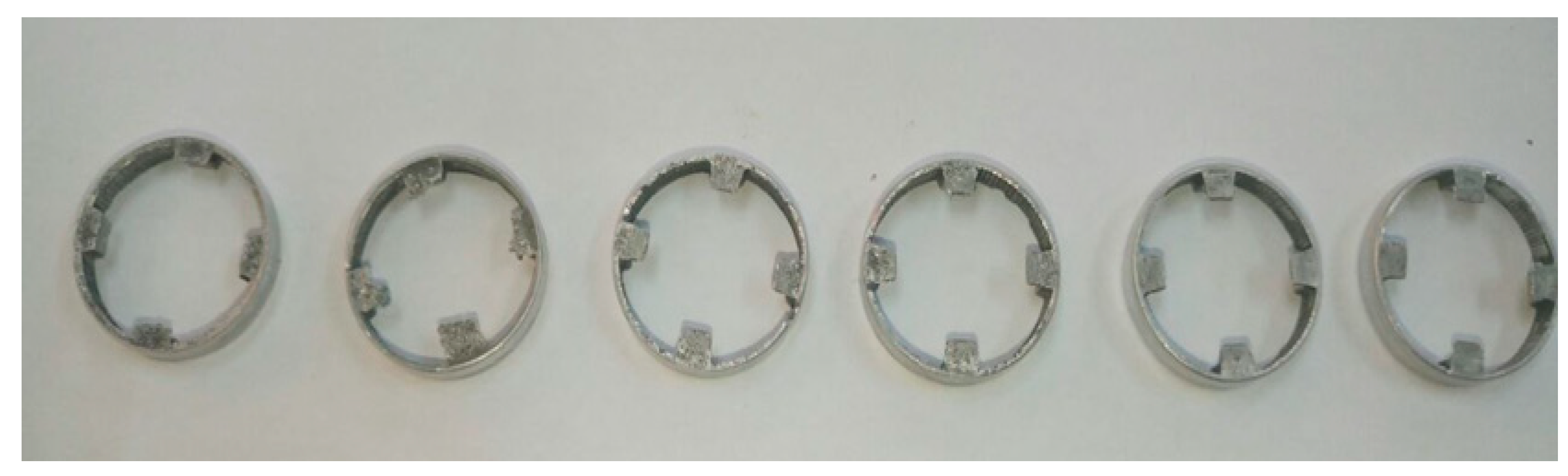
3.5. Morphological Observation
3.6. Oxidation
4. Conclusions
Author Contributions
Funding
Acknowledgments
Conflicts of Interest
References
- Rabinow, J. The Magnetic Fluid Clutch. Trans. Am. Inst. Electr. Eng. 1948, 67, 1308–1315. [Google Scholar] [CrossRef]
- Ubaidillah; Mazlan, S.A.; Sutrisno, J.; Zamzuri, H. Potential Applications of Magnetorheological Elastomers. Appl. Mech. Mater. 2014, 663, 695–699. [Google Scholar] [CrossRef]
- Aziz, S.A.A.; Mazlan, S.A.; Ismail, N.I.N.; Ubaidillah, U.; Choi, S.B.; Khairi, M.H.A.; Yunus, N.A. Effects of multiwall carbon nanotubes on viscoelastic properties of magnetorheological elastomers. Smart Mater. Struct. 2016, 25, 1–10. [Google Scholar] [CrossRef]
- de Vicente, J.; Klingenberg, D.J.; Hidalgo-Alvarez, R. Magnetorheological fluids: a review. Soft Matter 2011, 7, 3701–3710. [Google Scholar] [CrossRef]
- Bahiuddin, I.; Mazlan, S.A.; Shapiai, I.; Imaduddin, F.; Ubaidillah; Choi, S.-B. Constitutive models of magnetorheological fluids having temperature-dependent prediction parameter. Smart Mater. Struct. 2018, 27, 095001. [Google Scholar] [CrossRef] [Green Version]
- Wahid, S.; Ismail, I.; Aid, S.; Rahim, M. Magneto-rheological defects and failures: A review. IOP Conf. Ser. Mater. Sci. Eng. 2016, 114, 012101. [Google Scholar] [CrossRef] [Green Version]
- Zhang, Q.; Liu, X.; Ren, Y.; Wang, L.; Hu, Y. Effect of Particle Size on the Wear Property of Magnetorheological Fluid. Adv. Mater. Sci. Eng. 2016, 2016, 7. [Google Scholar] [CrossRef]
- Laherisheth, Z.; Upadhyay, R.V. Temperature dependence quasi-static measurements on a magnetorheological fluid having plate-like iron particles as dispersed phase. J. Intell. Mater. Syst. Struct. 2016, 27, 1329–1336. [Google Scholar] [CrossRef]
- Lee, C.H.; Lee, D.W.; Choi, J.Y.; Choi, S.B.; Cho, W.O.; Yun, H.C. Tribological Characteristics Modification of Magnetorheological Fluid. J. Tribol. 2011, 133, 031801. [Google Scholar] [CrossRef]
- Wang, J.; Meng, G. Magnetorheological fluid devices: principles, characteristics and applications in mechanical engineering. Proc. Inst. Mech. Eng. Part L J. Mater. Des. Appl. 2005, 215, 165–174. [Google Scholar] [CrossRef]
- Carlson, J.D. Critical factors for MR fluids in vehicle systems. Int. J. Veh. Des. 2003, 33, 207–217. [Google Scholar] [CrossRef]
- Hreinsson, E. Durability of a Magnetorheological Fluid in a Prosthetic Knee Joint. Ph.D. Thesis, University of Iceland, Reykjavik, Iceland, 2011. [Google Scholar]
- Ulicny, J.C.; Balogh, M.P.; Potter, N.M.; Waldo, R.A. Magnetorheological fluid durability test-Iron analysis. Mater. Sci. Eng. A 2007, 443, 16–24. [Google Scholar] [CrossRef]
- Desrosiers, J.-F.; Bigué, J.-P.L.; Denninger, M.; Julió, G.; Plante, J.-S.; Charron, F. Preliminary investigation of magneto-rheological fluid durability in continuous slippage clutch. J. Phys. Conf. Ser. 2013, 412, 012022. [Google Scholar] [CrossRef]
- Carlson, J.D. What Makes a Good MR Fluid? J. Intell. Mater. Syst. Struct. 2002, 13, 431–435. [Google Scholar] [CrossRef]
- Smith, A.L.; Ulicny, J.C.; Kennedy, L.C. Magnetorheological fluid fan drive for trucks. J. Intell. Mater. Syst. Struct. 2007, 18, 1131–1136. [Google Scholar] [CrossRef]
- Roupec, J.; Mazůrek, I. Stability of Magnetorheological Effect during Long Term Operation. Mechatronics 2011, 561–567. [Google Scholar] [CrossRef]
- Roupec, J.; Mazůrek, I.; Strecker, Z.; Klapka, M. The behavior of the MR fluid during durability test. J. Phys. Conf. Ser. 2013, 412, 012024. [Google Scholar] [CrossRef]
- Ichwan, B.; Mazlan, S.A.; Imaduddin, F.; Ubaidillah; Koga, T.; Idris, M.H. Development of a modular MR valve using meandering flow path structure. Smart Mater. Struct. 2016, 25, 037001. [Google Scholar] [CrossRef]
- Imaduddin, F.; Mazlan, S.A.; Ubaidillah; Zamzuri, H.; Fatah, A.Y.A. Testing and parametric modeling of magnetorheological valve with meandering flow path. Nonlinear Dyn. 2016, 85, 287–302. [Google Scholar] [CrossRef]
- Imaduddin, F. A Novel Magnetorheological Valve with Meandering Flow Path Structure. Ph.D. Thesis, Universiti Teknologi Malaysia, Kuala Lumpur, Malaysia, 2015. [Google Scholar]
- Wang, X.; Gordaninejad, F. Study of magnetorheological fluids at high shear rates. Rheol. Acta 2006, 45, 899–908. [Google Scholar] [CrossRef]
- Ahmadian, M.; Norris, J.A. Experimental analysis of magnetorheological dampers when subjected to impact and shock loading. Commun. Nonlinear Sci. Numer. Simul. 2008, 13, 1978–1985. [Google Scholar] [CrossRef]
- Cvek, M.; Mrlik, M.; Pavlinek, V. A rheological evaluation of steady shear magnetorheological flow behavior using three-parameter viscoplastic models. J. Rheol. 2016, 60, 687–694. [Google Scholar] [CrossRef] [Green Version]
- Nott, P.R.; Brady, J.F. Pressure-driven flow of suspensions: Simulation and theory. J. Fluid Mech. 1994, 275, 157–199. [Google Scholar] [CrossRef]
- Sánchez, M.; Carlevaro, C.M.; Pugnaloni, L.A. Effect of particle shape and fragmentation on the response of particle dampers. J. Vib. Control 2014, 20, 1846–1854. [Google Scholar] [CrossRef]
- Baranwal, D.; Deshmukh, T.S. MR-Fluid Technology and Its Application—A Review. Int. J. Emerg. Technol. Adv. Eng. 2012, 2, 563–569. [Google Scholar]
- Golden, M.A.; Ulicny, J.C.; Snavely, K.S.; Smith, A.L. Magnetorheological Fluids. U.S. Patent 6932917 B2, 23 August 2005. [Google Scholar]
- Olabi, A.G.; Grunwald, A. Design and application of magneto-rheological fluid. Mater. Des. 2007, 28, 2658–2664. [Google Scholar] [CrossRef] [Green Version]
- Phulé, P.P. Magnetorheological (MR) Fluids: Principles And Applications. Smart Mater. Bull. 2001, 2001, 7–10. [Google Scholar] [CrossRef]
- Plachy, T.; Kutalkova, E.; Sedlacik, M.; Vesel, A.; Masar, M. Impact of corrosion process of carbonyl iron particles on magnetorheological behavior of their suspensions. J. Ind. Eng. Chem. 2018, 66, 362–369. [Google Scholar] [CrossRef]


| Appearance | Dark Grey Liquid |
|---|---|
| Solid Weight Percentage (wt %) | 77–80 |
| Density (g/m3) | 2.75–2.95 |
| Shear Stress (kPa @ 1500/s 570 mT) | 68.0 ± 7 |
| Viscosity (Pa s) | 0.106 + 0.020 |
| Flash Point (°C) | >140 |
| Operating Temperature (°C) | −40 to +140 |
| Sedimentation Stability (vol %/30 days) | 4.00 |
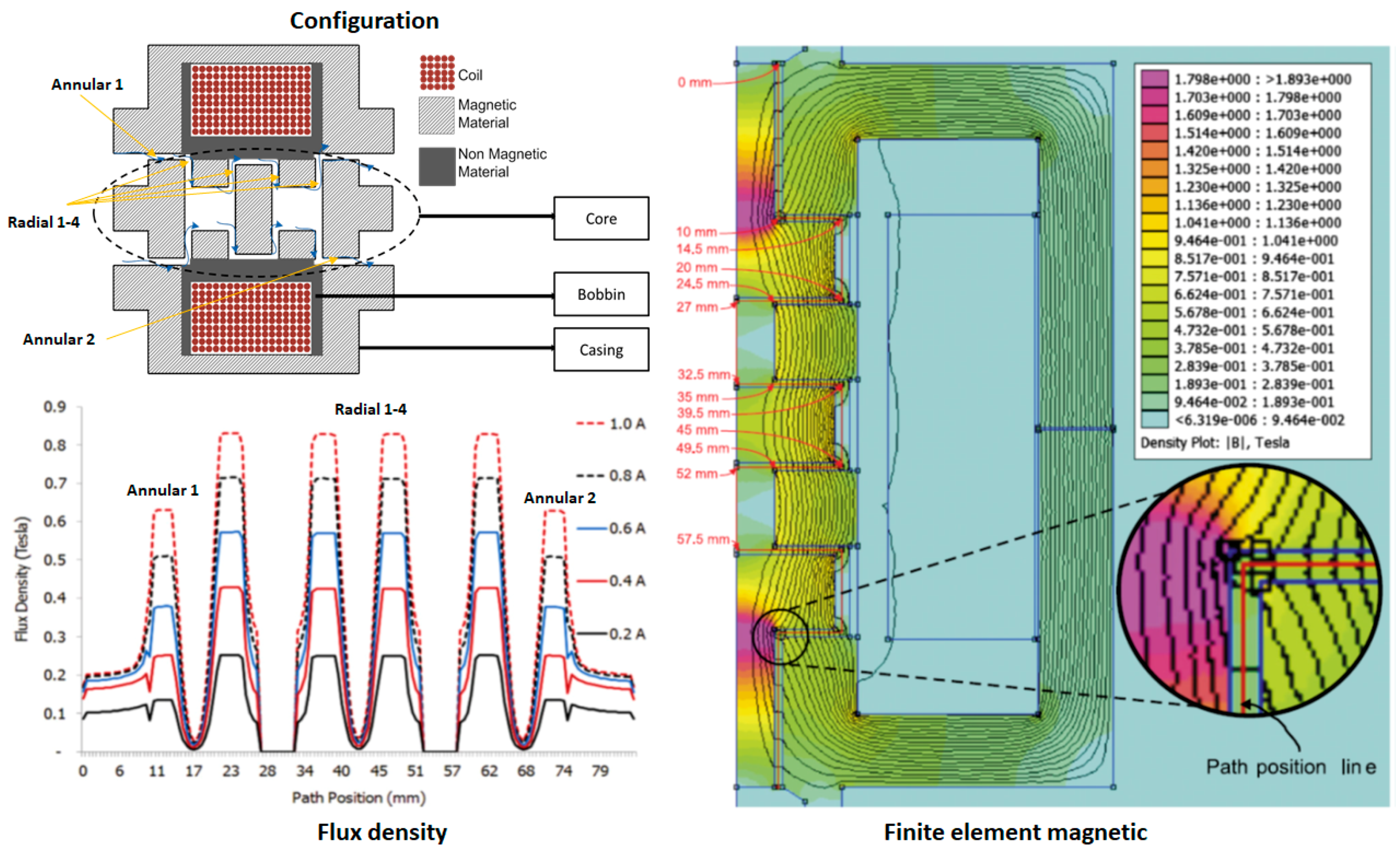
| Current (A) | Flux Density in MR Valve Areas (T) | |||||
|---|---|---|---|---|---|---|
| Annular 1 | Radial 1 | Radial 2 | Radial 3 | Radial 4 | Annular 2 | |
| 1 | 0.63 | 0.84 | 0.84 | 0.84 | 0.84 | 0.63 |
| 0.8 | 0.52 | 0.72 | 0.72 | 0.72 | 0.72 | 0.52 |
| 0.6 | 0.38 | 0.58 | 0.58 | 0.58 | 0.58 | 0.38 |
| 0.5 | 0.31 | 0.50 | 0.50 | 0.50 | 0.50 | 0.31 |
| 0.4 | 0.24 | 0.43 | 0.43 | 0.43 | 0.43 | 0.24 |
| 0.2 | 0.13 | 0.24 | 0.24 | 0.24 | 0.24 | 0.14 |
© 2018 by the authors. Licensee MDPI, Basel, Switzerland. This article is an open access article distributed under the terms and conditions of the Creative Commons Attribution (CC BY) license (http://creativecommons.org/licenses/by/4.0/).
Share and Cite
Utami, D.; Ubaidillah; Mazlan, S.A.; Imaduddin, F.; Nordin, N.A.; Bahiuddin, I.; Abdul Aziz, S.A.; Mohamad, N.; Choi, S.-B. Material Characterization of a Magnetorheological Fluid Subjected to Long-Term Operation in Damper. Materials 2018, 11, 2195. https://0-doi-org.brum.beds.ac.uk/10.3390/ma11112195
Utami D, Ubaidillah, Mazlan SA, Imaduddin F, Nordin NA, Bahiuddin I, Abdul Aziz SA, Mohamad N, Choi S-B. Material Characterization of a Magnetorheological Fluid Subjected to Long-Term Operation in Damper. Materials. 2018; 11(11):2195. https://0-doi-org.brum.beds.ac.uk/10.3390/ma11112195
Chicago/Turabian StyleUtami, Dewi, Ubaidillah, Saiful A. Mazlan, Fitrian Imaduddin, Nur A. Nordin, Irfan Bahiuddin, Siti Aishah Abdul Aziz, Norzilawati Mohamad, and Seung-Bok Choi. 2018. "Material Characterization of a Magnetorheological Fluid Subjected to Long-Term Operation in Damper" Materials 11, no. 11: 2195. https://0-doi-org.brum.beds.ac.uk/10.3390/ma11112195