Characterization and Cellular Internalization of Spherical Cellulose Nanocrystals (CNC) into Normal and Cancerous Fibroblasts

 , , and
Abstract
:1. Introduction
2. Materials and Methods
2.1. Materials
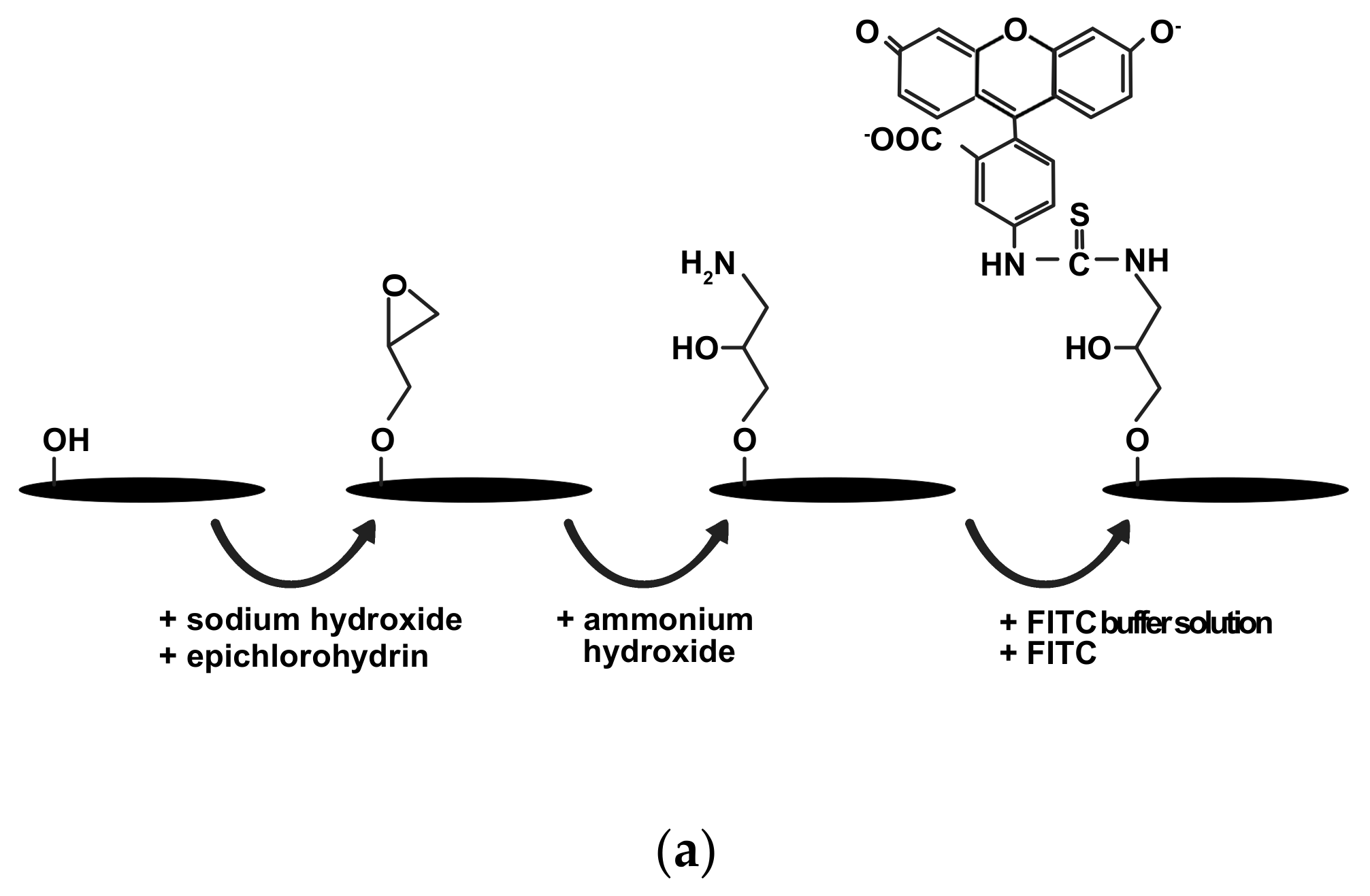
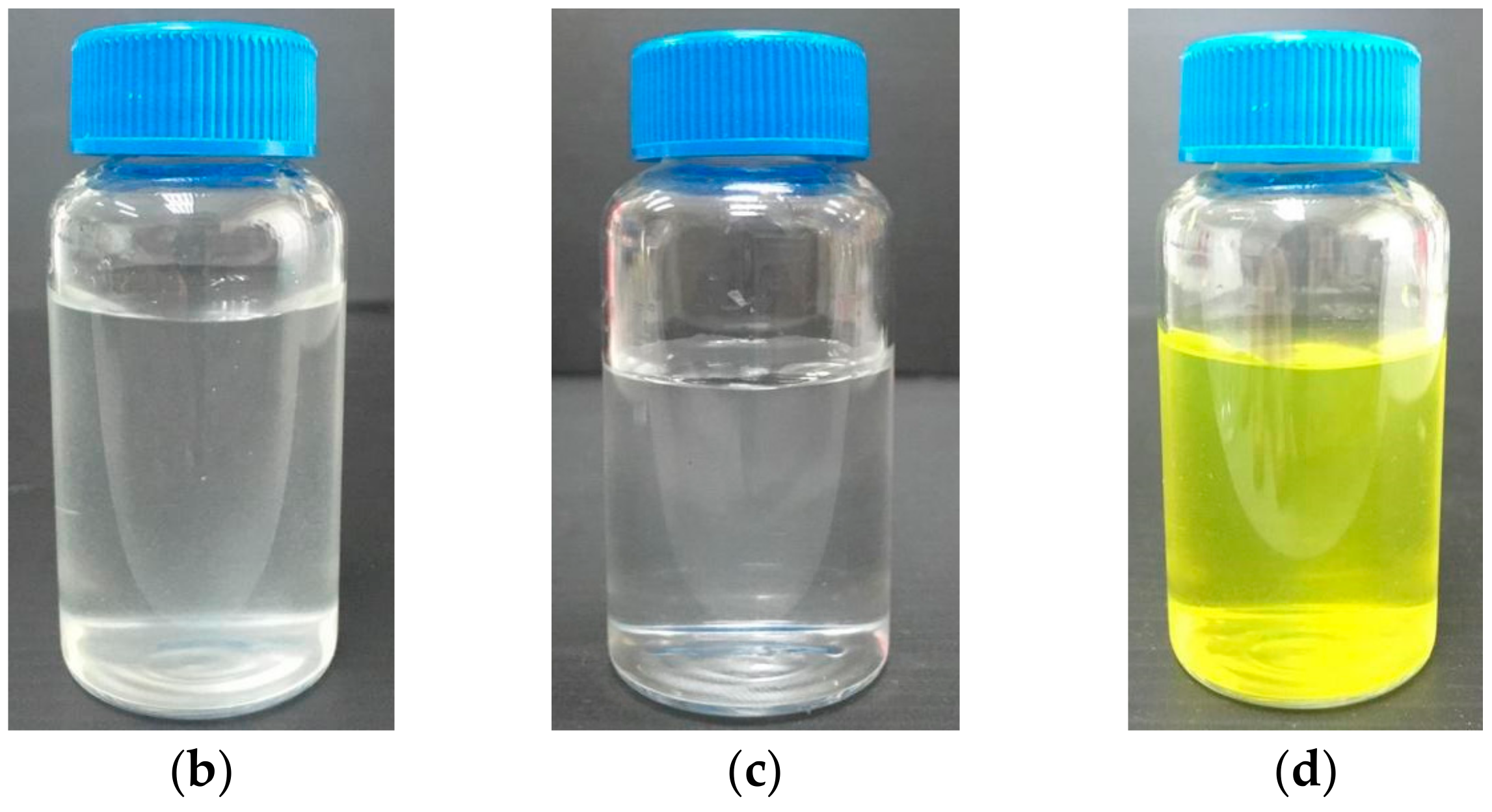
2.2. CNC and FITC-CNC Synthesis
2.3. Characterization of CNF, CNC, and FITC-CNC
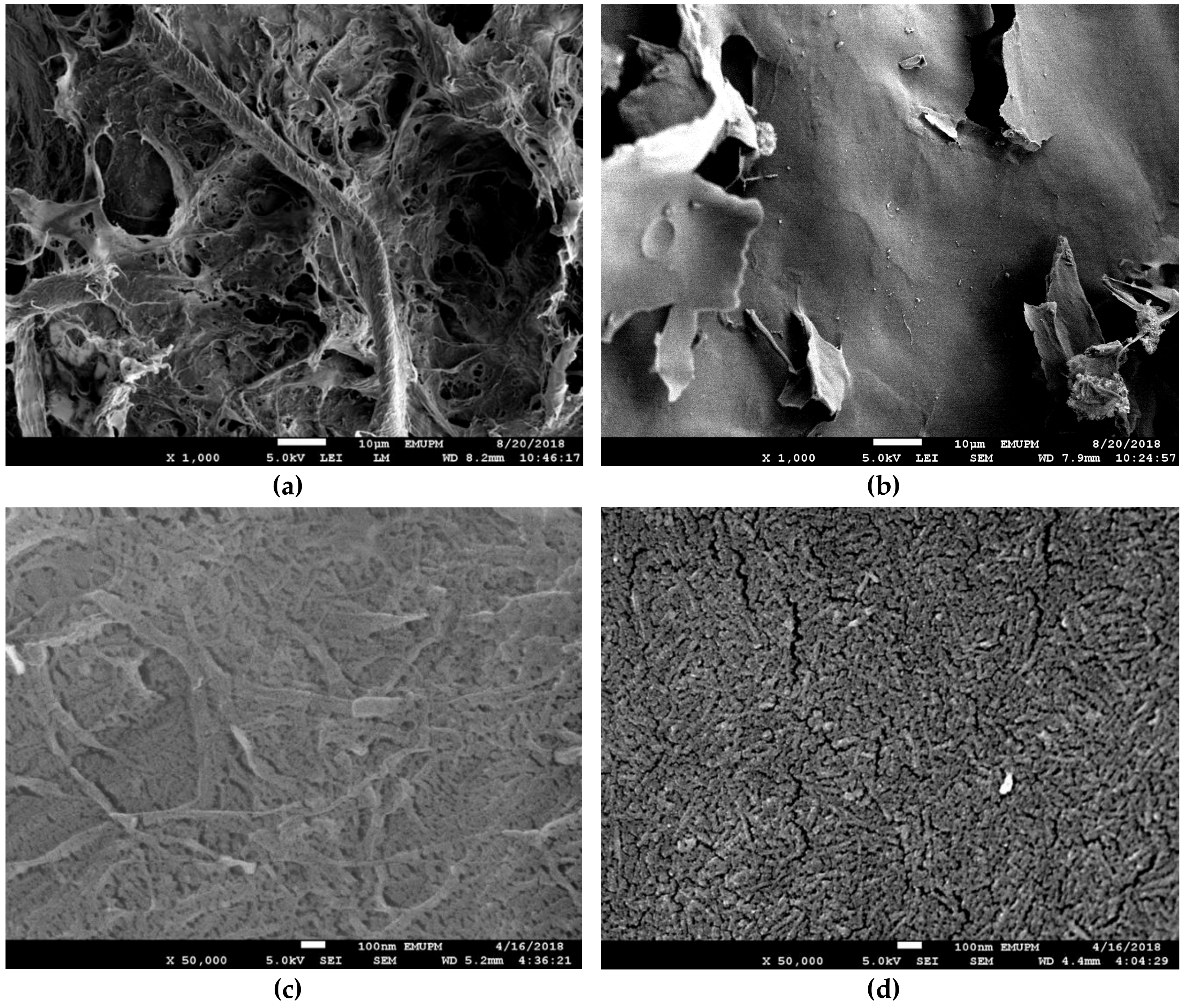
2.3.1. Field Emission Scanning Electron Microscopy (FESEM)
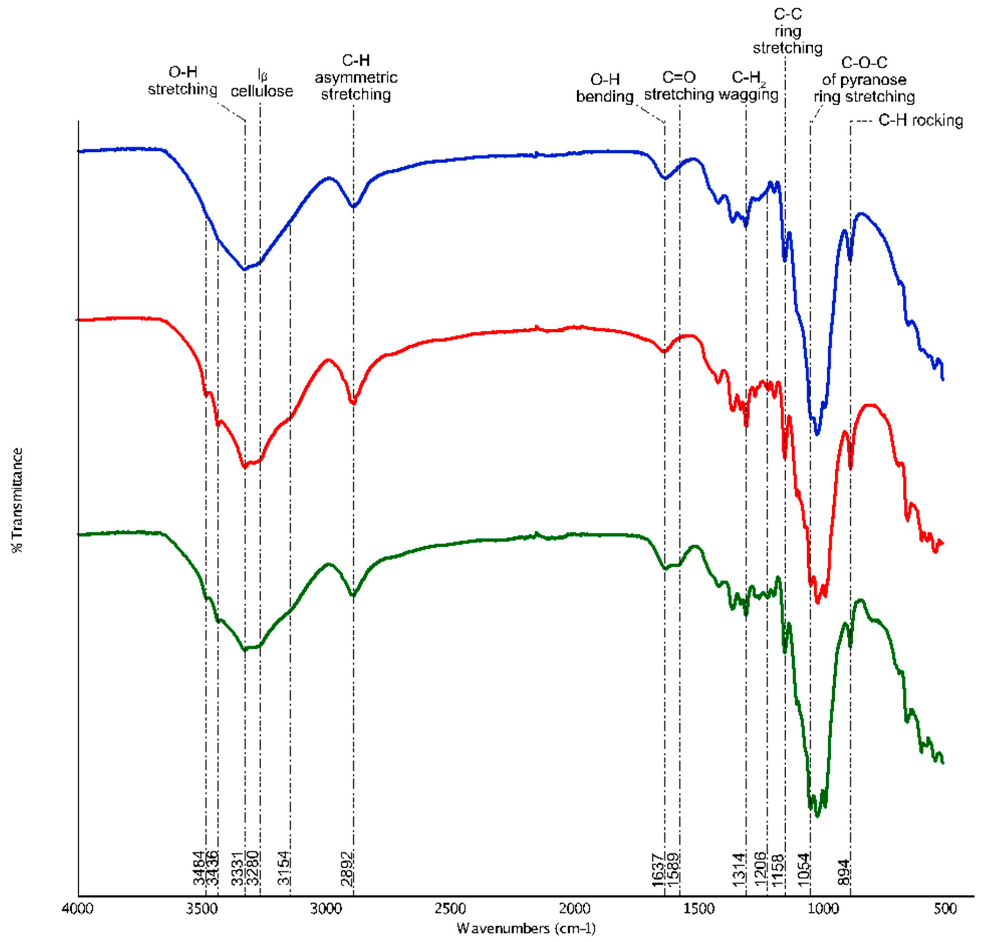
2.3.2. Attenuated Total Reflection Fourier Transmission Infrared (ATR-FTIR)
2.3.3. Zeta Potential and Polydispersity Index
2.3.4. Atomic Force Microscopy (AFM)
2.4. Cytotoxicity and Cell Viability Assay
2.4.1. Cell Culture
2.4.2. MTT Assay
2.5. Cellular Internalization Study
2.6. Statistical Analysis
3. Results and Discussion
3.1. Nanocellulose Synthesis and Characterization
3.1.1. FESEM
3.1.2. ATR-FTIR
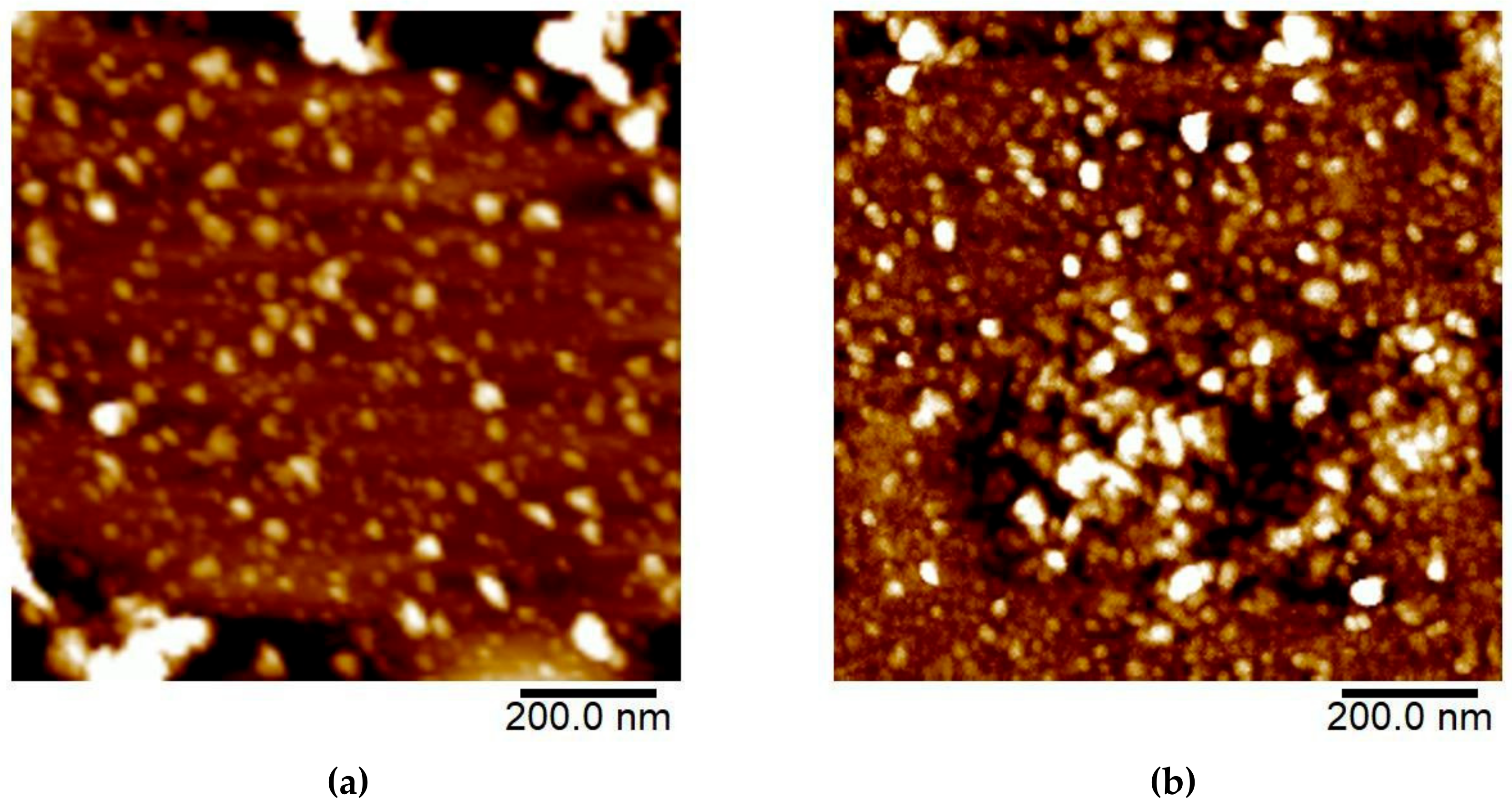
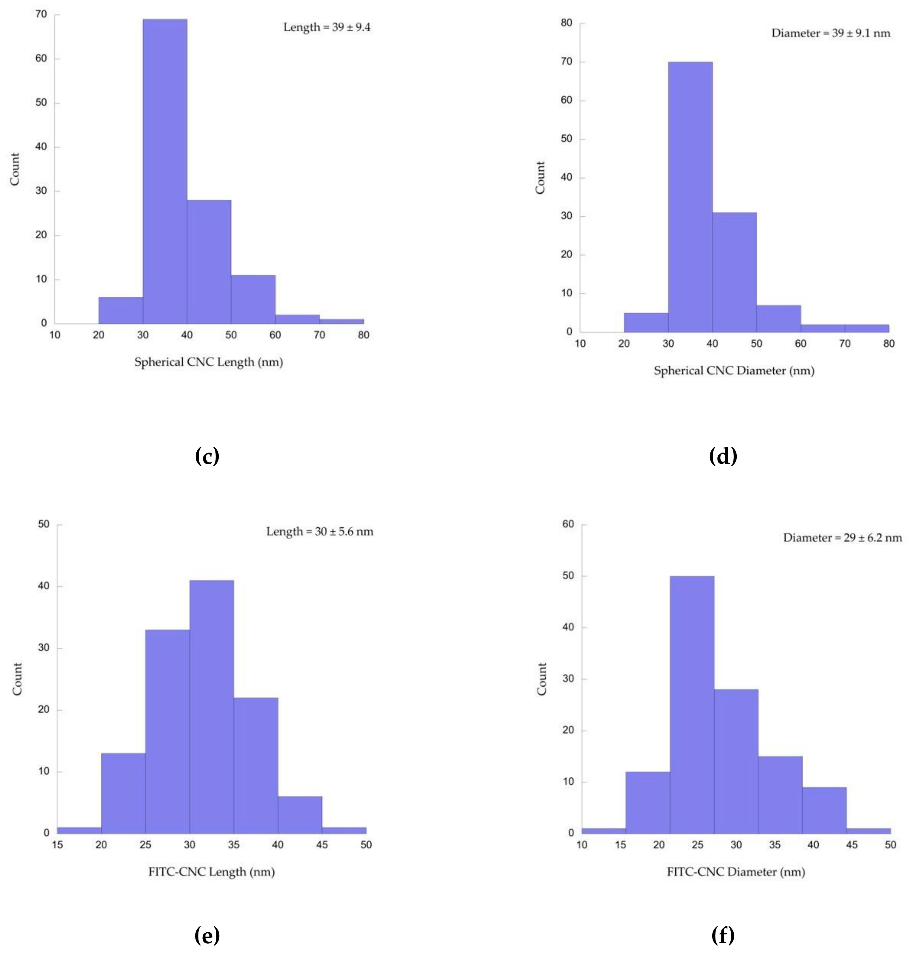
3.1.3. AFM
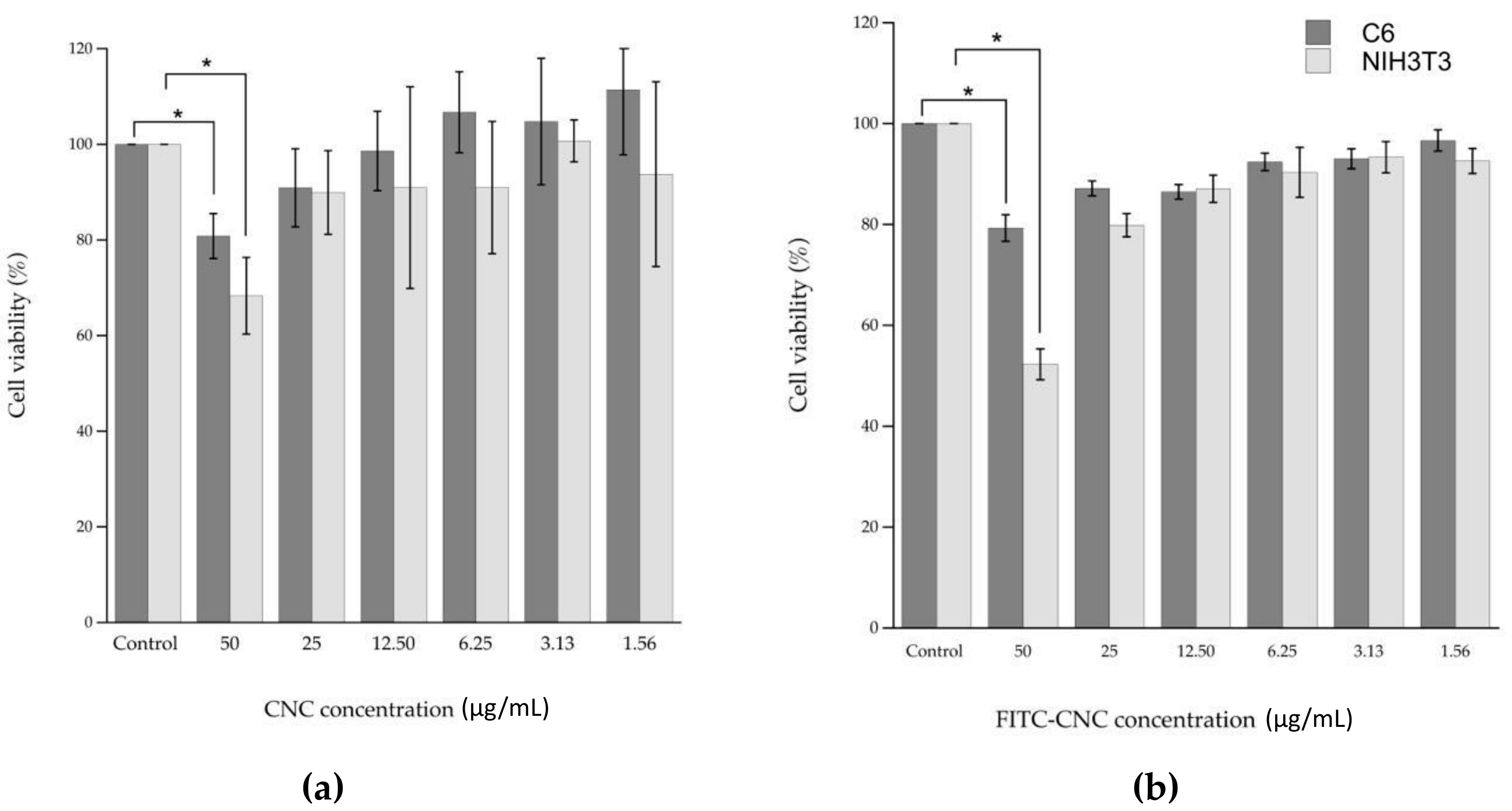
3.2. Nanocellulose Cytotoxicity
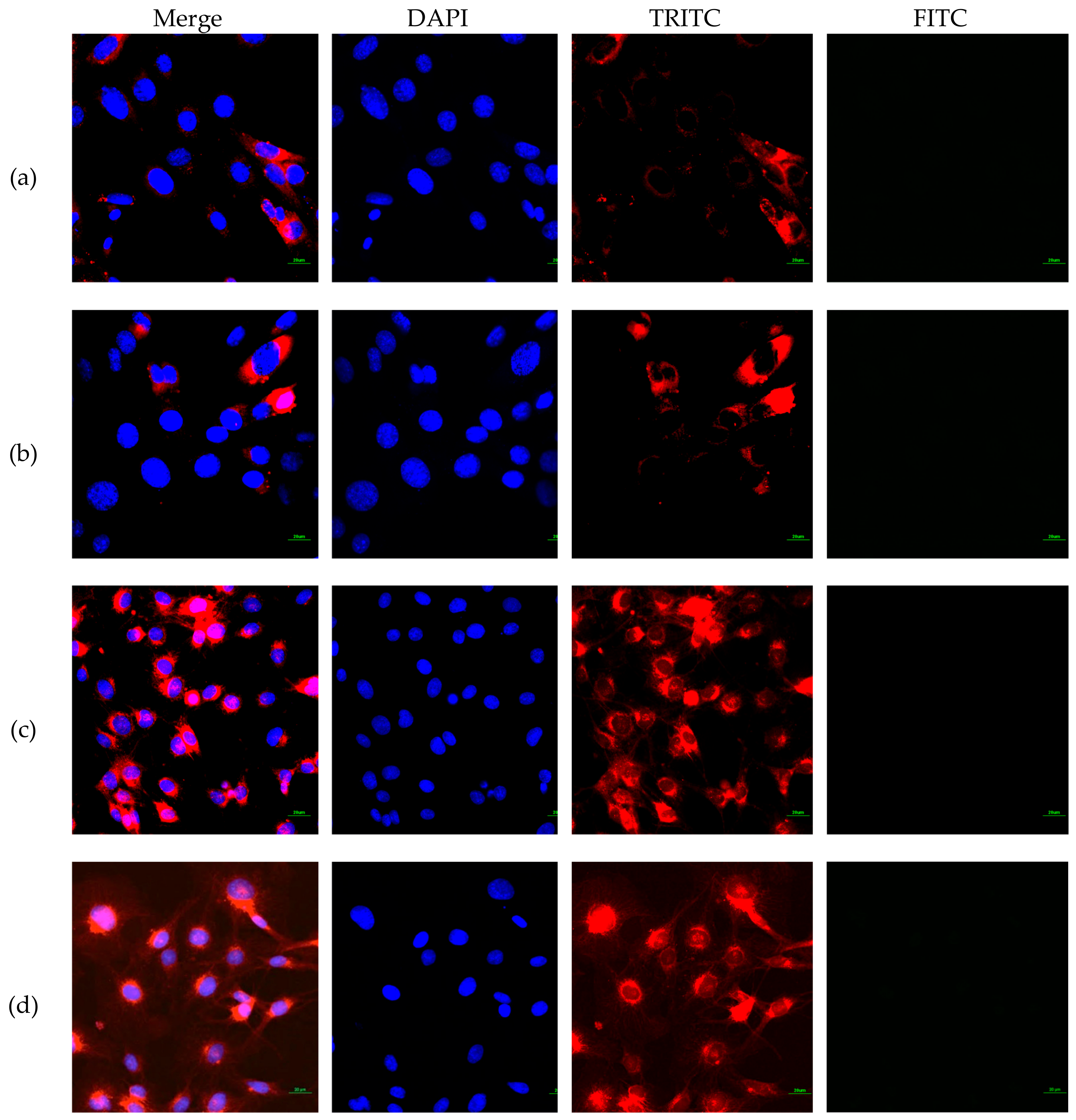
3.3. FITC-CNC Cellular Internalization
4. Conclusions
Supplementary Materials
Author Contributions
Funding
Conflicts of Interest
References
- Damyanov, C.A.; Maslev, I.K.; Pavlov, V.S.; Avramov, L. Conventional Treatment of Cancer Realities and Problems. Ann. Complement. Altern. Med. 2018, 1, 1–9. [Google Scholar]
- Leary, M.; Heerboth, S.; Lapinska, K.; Sarkar, S. Sensitization of Drug Resistant Cancer Cells: A Matter of Combination Therapy. Cancers 2018, 10, 483. [Google Scholar] [CrossRef] [PubMed]
- Senapati, S.; Mahanta, A.K.; Kumar, S.; Maiti, P. Controlled Drug Delivery Vehicles for Cancer Treatments and Their Performance. Signal Transduct. Target. Ther. 2018, 3, 7. [Google Scholar] [CrossRef] [PubMed]
- Helleday, T. Chemotherapy-induced toxicity—A secondary effect caused by released DNA? Ann. Oncol. 2017, 28, 2054–2055. [Google Scholar] [CrossRef] [PubMed]
- Moorthi, C.; Manavalan, R.; Kathiresan, K. Nanotherapeutics to Overcome Conventional Cancer Chemotherapy Limitations. J. Pharm. Pharm. Sci. 2011, 14, 67–77. [Google Scholar]
- Zhao, C.Y.; Cheng, R.; Yang, Z.; Tian, Z.M. Nanotechnology for Cancer Therapy Based on Chemotherapy. Molecules 2018, 23, 826. [Google Scholar] [CrossRef]
- Rizvi, S.A.A.; Saleh, A.M. Applications of Nanoparticle Systems in Drug Delivery Technology. Saudi Pharm. J. 2018, 26, 64–70. [Google Scholar] [CrossRef] [PubMed]
- Li, Y.; Wang, B.; Ma, M.; Wang, B. Review of Recent Development on Preparation, Properties, and Applications of Cellulose-Based Functional Materials. Int. J. Polym. Sci. 2018, 2018, 1–18. [Google Scholar] [CrossRef]
- Abitbol, T.; Rivkin, A.; Cao, Y.; Nevo, Y.; Abraham, E.; Ben-Shalom, T.; Lapidot, S.; Shoseyov, O. Nanocellulose, a tiny fiber with huge applications. Curr. Opin. Biotechnol. 2016, 39, 76–88. [Google Scholar] [CrossRef]
- Kim, J.; Shim, B.; Kim, H.; Lee, Y.; Min, S.; Jang, D.; Abas, Z.; Kim, J. Review of nanocellulose for sustainable future materials. Int. J. Precis. Eng. Manuf. Green Technol. 2015, 2, 197–213. [Google Scholar] [CrossRef] [Green Version]
- Sofla, M.; Brown, R.; Tsuzuki, T.; Rainey, T. A comparison of cellulose nanocrystals and cellulose nanofibres extracted from bagasse using acid and ball milling methods. Adv. Nat. Sci. Nanosci. Nanotechnol. 2016, 7, 035004. [Google Scholar] [CrossRef]
- Li, Y.; Kröger, M.; Liu, W.K. Shape Effect in Cellular Uptake of PEGylated Nanoparticles: Comparison Between Sphere, Rod, Cube and Disk. Nanoscale 2015, 40, 16631–16646. [Google Scholar] [CrossRef] [PubMed]
- Dasgupta, S.; Auth, T.; Gompper, G. Shape and Orientation Mater for the Cellular Uptake of Nonspherical Particles. Nano Lett. 2014, 14, 687–693. [Google Scholar] [CrossRef] [PubMed]
- Roman, M.; Dong, S.; Anjali, H.; Lee, Y. Cellulose Nanocrystals for Drug Delivery. In Polysaccharides for Drug Delivery and Pharmaceutical Applications; Marchessault, R., Ravenelle, F., Zhu, X., Eds.; American Chemical Society: Washington, DC, USA, 2009; pp. 81–91. [Google Scholar]
- Mahmoud, K.; Mena, J.; Male, K.; Hrapovic, S.; Kamen, A.; Luong, J. Effect of Surface Charge on the Cellular Uptake and Cytotoxicity of Fluorescent Labeled Cellulose Nanocrystals. ACS Appl. Mater. Interfaces 2010, 2, 2924–2932. [Google Scholar] [CrossRef] [PubMed] [Green Version]
- Erdem, J.S.; Alswady-Hoff, M.; Ervik, T.K.; Skare, Ø.; Elingsen, D.G.; Zienolddiny, S. Cellulose Nanocrystals Modulate Alveolar Macrophage Phenotype and Phagocytic Function. Biomaterials 2019, 203, 31–42. [Google Scholar] [CrossRef] [PubMed]
- Liebert, T.; Kostag, M.; Wotschadlo, J.; Heinze, T. Stable Cellulose Nanospheres for Cellular Uptake. Macromol. Biosci. 2011, 11, 1387–1392. [Google Scholar] [CrossRef]
- Jin, E.; Guo, J.; Yang, F.; Zhu, Y.; Song, J.; Jin, Y.; Rojas, O.J. On the polymorphic and morphological changes of cellulose nanocrystals (CNC-I) upon mercerization and conversion to CNC-II. Carbohydr. Polym. 2016, 143, 327–335. [Google Scholar] [CrossRef] [PubMed]
- Dong, S.; Hirani, A.; Colacino, K.; Lee, Y.; Roman, M. Cytotoxicity and Cellular Uptake of Cellulose Nanocrystals. Nano Life 2012, 2, 1241006. [Google Scholar] [CrossRef]
- Romli, F.; Abu, N.; Khorshid, F.A.; Najmuddin, S.U.F.S.; Keong, Y.S.; Mohamad, N.E.; Hamid, M.; Alitheen, N.B.; Rahman, N.M.A.N.A. The Growth Inhibitory Potential and Antimetastatic Effect of Camel Urine on Breast Cancer Cells In Vitro and In Vivo. Integr. Cancer Ther. 2017, 16, 540–555. [Google Scholar] [CrossRef]
- Ghaemi, F.; Abdullah, L.C.; Rahman, N.M.A.N.A.; Najmuddin, S.U.F.S.; Abdi, M.M.; Hidayah, A. Synthesis and comparative study of thermal, electrochemical, and cytotoxicity properties of graphene flake and sheet. Res. Chem. Intermed. 2017. [Google Scholar] [CrossRef]
- Mosmann, T. Rapid colorimetric assay for cellular growth and survival: Application to proliferation and cytotoxicity assays. J. Immunol. Methods 1983, 65, 55–63. [Google Scholar] [CrossRef]
- Dussán, K.J.; Silva, D.D.V.; Moraes, E.J.C.; Arruda, P.V.; Felipe, M.G.A. Dilute-acid Hydrolysis of Cellulose to Glucose from Sugarcane Bagasse. Chem. Eng. Trans. 2014, 38, 433–438. [Google Scholar]
- Nielsen, L.; Eyley, S.; Thielemans, W.; Aylott, J. Dual fluorescent labelling of cellulose nanocrystals for pH sensing. Chem. Commun. 2010, 46, 8929. [Google Scholar] [CrossRef] [PubMed]
- Dong, S.; Maren, R. Fluorescently labeled cellulose nanocrystals for bioimaging applications. J. Am. Chem. Soc. 2007, 45, 13810–13811. [Google Scholar] [CrossRef] [PubMed]
- Peng, Y.; Gardner, D.; Han, Y. Drying cellulose nanofibrils: In search of a suitable method. Cellulose 2011, 19, 91–102. [Google Scholar] [CrossRef]
- Han, J.; Zhou, C.; Wu, Y.; Liu, F.; Wu, Q. Self-Assembling Behavior of Cellulose Nanoparticles during Freeze-Drying: Effect of Suspension Concentration, Particle Size, Crystal Structure, and Surface Charge. Biomacromolecules 2013, 14, 1529–1540. [Google Scholar] [CrossRef]
- Hai, L. Nanocellulose from Different Cellulose Sources and Their All—Cellulose Composite Properties; Graduate; Chungnam National University: Daejeon, Korea, 2015. [Google Scholar]
- Habibi, Y.; Lucia, L.; Rojas, O. Cellulose Nanocrystals: Chemistry, Self-Assembly, and Applications. Chem. Rev. 2010, 110, 3479–3500. [Google Scholar] [CrossRef]
- Peng, Y.; Gardner, D.; Han, Y.; Cai, Z.; Tshabalala, M. Influence of drying method on the surface energy of cellulose nanofibrils determined by inverse gas chromatography. J. Colloid Interface Sci. 2013, 405, 85–95. [Google Scholar] [CrossRef]
- Two-Component Surface Energy Characterization as a Predictor of Wettability and Dispersability; KRUSS Application Report AR213e; KRUSS: Hamburg, Germany, 2019.
- Kumar, A.; Singh, Y.; Choudhury, V.; Bhardwaj, N. Characterization of Cellulose Nanocrystals Produced by Acid-Hydrolysis from Sugarcane Bagasse as Agro-Waste. J. Mater. Phys. Chem. 2014, 2, 1–8. [Google Scholar]
- Wulandari, W.; Rochliadi, A.; Arcana, I. Nanocellulose Prepared by Acid Hydrolysis of Isolated Cellulose from Sugarcane Bagasse. In IOP Conference Series: Materials Science and Engineering; IOP Publishing: Bristol, UK, 2016; Volume 107, p. 012045. [Google Scholar]
- Ilyas, R.; Sapuan, S.; Ishak, M. Isolation and characterization of nanocrystalline cellulose from sugar palm fibres (Arenga Pinnata). Carbohydr. Polym. 2018, 181, 1038–1051. [Google Scholar] [CrossRef]
- Rahman, N.H.A.R.; Chieng, B.W.; Ibrahim, N.A.; Rahman, N.A. Ectraction and Characterization of Cellulose Nanocrystals from Tea Leaf Waste Fibers. Polymers 2017, 9, 588. [Google Scholar] [CrossRef] [PubMed]
- Chieng, B.W.; Lee, S.H.; Ibrahim, N.A.; Then, Y.Y.; Loo, Y.Y. Isolation and Characterization of Cellulose Nanocrystals from Oil Palm Mesocarp Fiber. Polymers 2017, 9, 355. [Google Scholar] [CrossRef] [PubMed]
- Hishikawa, Y.; Togawa, E.; Kondo, T. Characterization of Individual Hydrogen Bonds in Crystalline Regenerated Cellulose Using Resolved Polarized FTIR Spectra. ACS Omega 2017, 2, 1469–1476. [Google Scholar] [CrossRef] [PubMed]
- Yang, Y.; Zhang, Y.; Lang, Y.; Yu, M. Structural ATR-IR Analysis of Cellulose Fibers Prepared from a NaOH Complex Aqueous Solution. In IOP Conference Series: Materials Science and Engineering; IOP Publishing: Bristol, UK, 2017; Volume 213, p. 012039. [Google Scholar]
- Yue, Y. A Comparative Study of Cellulose I and II Fibers and Nanocrystals. Master’s Thesis, Louisiana State University, Baton Rouge, LA, USA, 2007. [Google Scholar]
- Langan, P.; Nishiyama, Y.; Chanzy, H. A Revised Structure and Hydrogen-Bonding System in Cellulose II from a Neutron Fiber Diffraction Analysis. J. Am. Chem. Soc. 1999, 121, 9940–9946. [Google Scholar] [CrossRef]
- Lu, P.; Hsieh, Y. Preparation and characterization of cellulose nanocrystals from rice straw. Carbohydr. Polym. 2012, 87, 564–573. [Google Scholar] [CrossRef]
- Fatah, I.; Khalil, H.; Hossain, M.; Aziz, A.; Davoudpour, Y.; Dungani, R.; Bhat, A. Exploration of a Chemo-Mechanical Technique for the Isolation of Nanofibrillated Cellulosic Fiber from Oil Palm Empty Fruit Bunch as a Reinforcing Agent in Composites Materials. Polymers 2014, 6, 2611–2624. [Google Scholar] [CrossRef] [Green Version]
- Khazraji, A.C.; Robert, S. Interaction Effects between Cellulose and Water in Nanocrystalline and Amorphous Regions: A Novel Approach Using Molecular Modeling. J. Nanomater. 2013, 2013, 44. [Google Scholar] [CrossRef]
- Ciolacu, D.; Ciolacu, F.; Popa, V. Amorphous Cellulose—Structure and Characterization. Cellul. Chem. Technol. 2011, 45, 13–21. [Google Scholar]
- Dong, S.; Cho, H.; Lee, Y.; Roman, M. Synthesis and Cellular Uptake of Folic Acid-Conjugated Cellulose Nanocrystals for Cancer Targeting. Biomacromolecules 2014, 15, 1560–1567. [Google Scholar] [CrossRef]
- Izham, M.N.M.; Hussin, Y.; Aziz, M.N.M.; Yeap, S.K.; Rahman, H.S.; Masaruddin, M.J.; Mohamad, N.E.; Abdullah, R.; Alitheen, N.B. Preparation and Characterization of Self Nano-Emulsifying Drug Delivary System Loaded with Citral and Its Antiproliferative Effect on Colorectal Cells In Vitro. Nanomaterials 2019, 9, 1028. [Google Scholar] [CrossRef]
- Gencoglu, A.; Camacho-Alanis, F.; Nguyen, V.T.; Nakano, A.; Ros, A.; Minerick, A. Quantification of pH Gradients and Implications in Insulator-Based Dielectrophoresis of Biomolecules. Electrophoresis 2011, 32, 2436–2447. [Google Scholar] [CrossRef] [PubMed]
- Mchedlov-Petrossyan, N.; Isaenko, Y.V.; Vodolazkaya, N.A.; Goga, S.T. Acid-Base Behavior of Fluorescein Isothiocyanate in Aqueous Media and in Micellar Surfactant Solutions. Chem. Prepr. Arch. 2003, 2003, 93–101. [Google Scholar]
- Sèbe, G.; Ham-Pichavant, F.; Ibarboure, E.; Koffi, A.L.C.; Tingaut, P. Supramolecular Structure Characterization of Cellulose II Nanowhiskers Produced by Acid Hydrolysis of Cellulose I Substrates. Biomacromolecules 2012, 13, 570–578. [Google Scholar] [CrossRef] [PubMed]
- Taurozzi, J.S.; Hackley, V.A.; Wiesner, M.R. Ultrasonic dispersion of nanoparticles for environmental, health and safety assessment—Issues and recommendations. Nanotoxicology 2010, 5, 711–729. [Google Scholar] [CrossRef] [PubMed]
- Jackson, J.; Letchford, K.; Wasserman, B.; Ye, L.; Hamad, W.; Burt, H. The use of nanocrystalline cellulose for the binding and controlled release of drugs. Int. J. Nanomed. 2011, 6, 321. [Google Scholar]
- Pachuau, L.; Jawaid, M.; Mohammad, F. Chapter 1: Application of Nanocellulose for Controlled Drug Delivery. In Nanocellulose and Nanohydrogel Matrices: Biotechnological and Biomedical Application; Wiley-VCH: Berlin, Germany, 2017; pp. 1–9. [Google Scholar]
- Leary, J. The Importance of Zeta Potential for Drug/Gene Delivery in Nanomedicine 2012. Available online: https://nanohub.org/resources/13793/download/2011.09.20-Leary-Malvern.pdf (accessed on 2 June 2019).
- Salatin, S.; Yari Khosroushahi, A. Overviews on the cellular uptake mechanism of polysaccharide colloidal nanoparticles. J. Cell. Mol. Med. 2017, 21, 1668–1686. [Google Scholar] [CrossRef] [PubMed] [Green Version]
- Lombardo, S.; Eyley, S.; Schütz, C.; Gorp, H.V.; Rosenfeldt, S.; Mooter, G.V.D.; Thielemans, W. Thermodynamic Study of the Interaction of Bovine Serum Albumin and Amino Acids with Cellulose Nnanocrystals. Langmuir 2017, 33, 5473–5481. [Google Scholar] [CrossRef] [PubMed]
- Lundqvist, M.; Stigler, J.; Elia, G.; Lynch, I.; Cedervall, T.; Dawson, K.A. Nanoparticle size and surface properties determine the protein corona with possible implications for biological impacts. Proc. Natl. Acad. Sci. USA 2008, 105, 14265–14270. [Google Scholar] [CrossRef] [Green Version]


| Sample | Zeta Potential (ξ) | Dispersity (Ð) |
|---|---|---|
| CNC | −38.6 mV | 0.703 |
| FITC-CNC | −17.7 mV | 0.371 |
© 2019 by the authors. Licensee MDPI, Basel, Switzerland. This article is an open access article distributed under the terms and conditions of the Creative Commons Attribution (CC BY) license (http://creativecommons.org/licenses/by/4.0/).
Share and Cite
Shazali, N.A.H.; Zaidi, N.E.; Ariffin, H.; Abdullah, L.C.; Ghaemi, F.; Abdullah, J.M.; Takashima, I.; Nik Abd. Rahman, N.M.A. Characterization and Cellular Internalization of Spherical Cellulose Nanocrystals (CNC) into Normal and Cancerous Fibroblasts. Materials 2019, 12, 3251. https://0-doi-org.brum.beds.ac.uk/10.3390/ma12193251
Shazali NAH, Zaidi NE, Ariffin H, Abdullah LC, Ghaemi F, Abdullah JM, Takashima I, Nik Abd. Rahman NMA. Characterization and Cellular Internalization of Spherical Cellulose Nanocrystals (CNC) into Normal and Cancerous Fibroblasts. Materials. 2019; 12(19):3251. https://0-doi-org.brum.beds.ac.uk/10.3390/ma12193251
Chicago/Turabian StyleShazali, Nur Aima Hafiza, Noorzaileen Eileena Zaidi, Hidayah Ariffin, Luqman Chuah Abdullah, Ferial Ghaemi, Jafri Malin Abdullah, Ichiro Takashima, and Nik Mohd Afizan Nik Abd. Rahman. 2019. "Characterization and Cellular Internalization of Spherical Cellulose Nanocrystals (CNC) into Normal and Cancerous Fibroblasts" Materials 12, no. 19: 3251. https://0-doi-org.brum.beds.ac.uk/10.3390/ma12193251