Forging of Mg-Al-Zn Magnesium Alloys on Screw Press and Forging Hammer

 ,
,  , , ,
, , ,  , and
, and 
Abstract
:1. Introduction
2. Materials and Methods
2.1. Stage 1
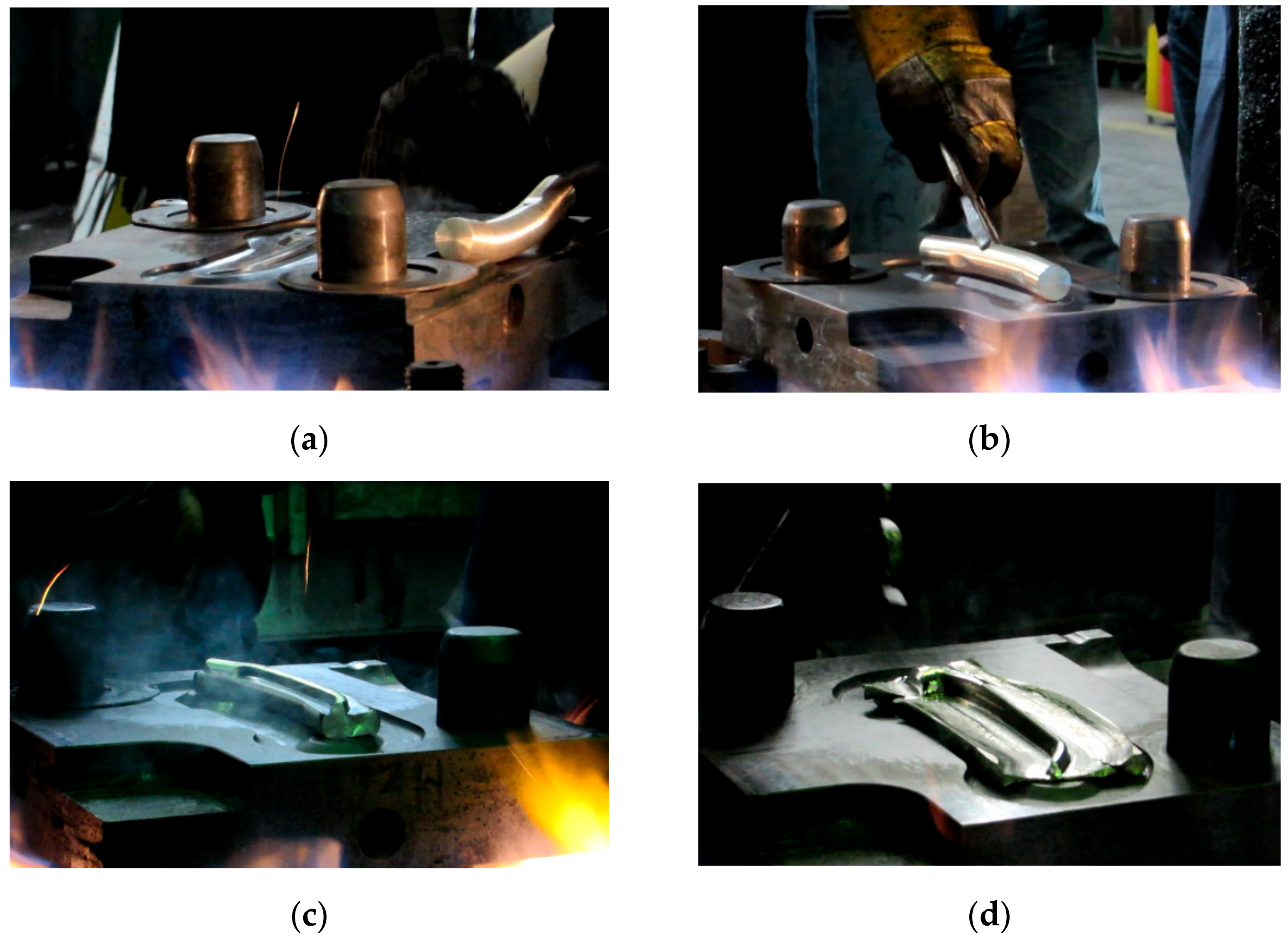
2.2. Stage 2
- Cutting the billet (bar) into the dimensions of ø22 × 170 mm;
- Preheating the billet to 410 °C for 22 min (1 min per 1 mm of the billet diameter);
- Forging operation in a bending cavity;
- Preliminary forging operation in a finish forging cavity, leaving an underforged portion of about 2 mm;
- Preheating the forged part;
- Forging in a finish forging cavity;
- Cooling the forged part in air or water.
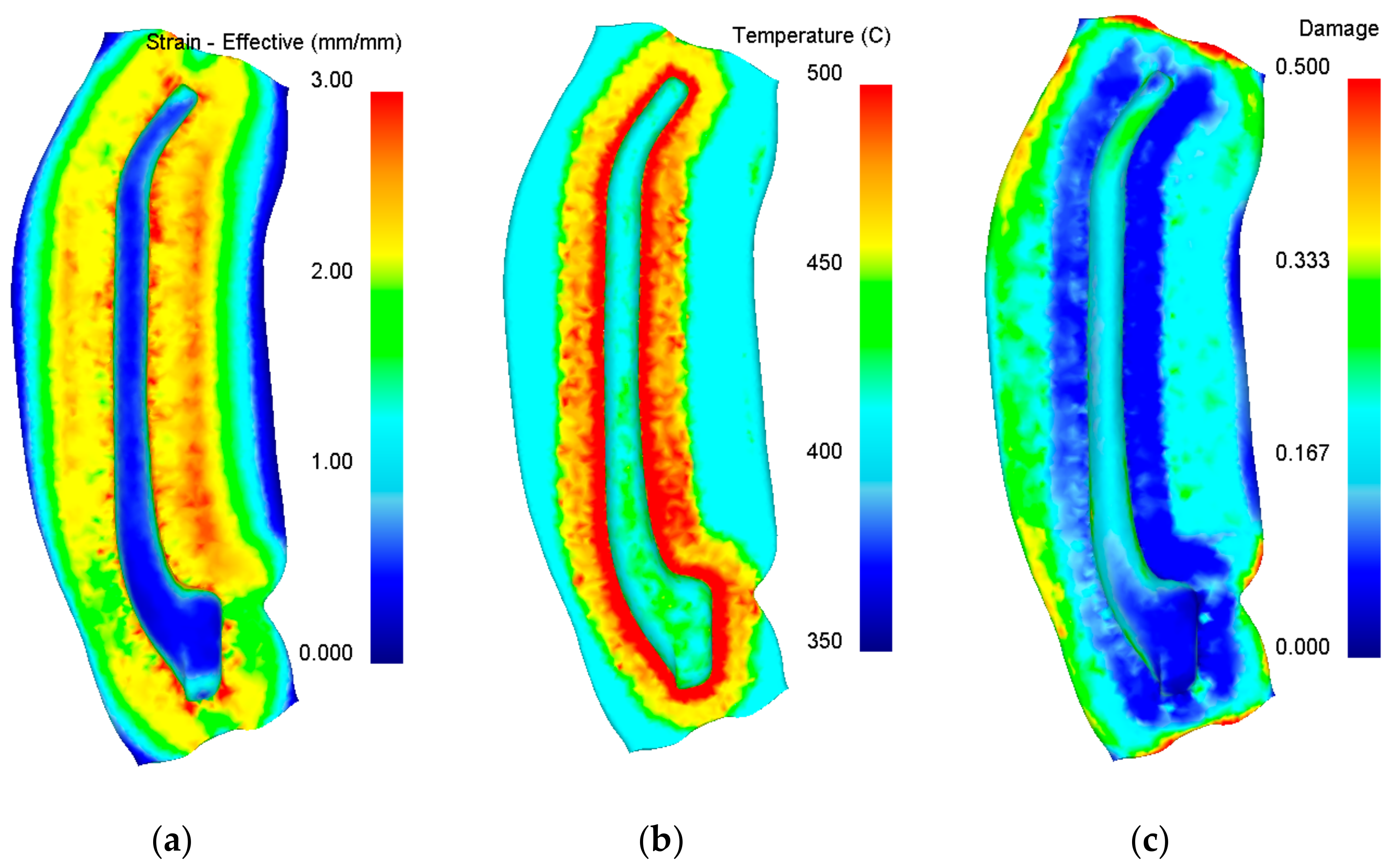
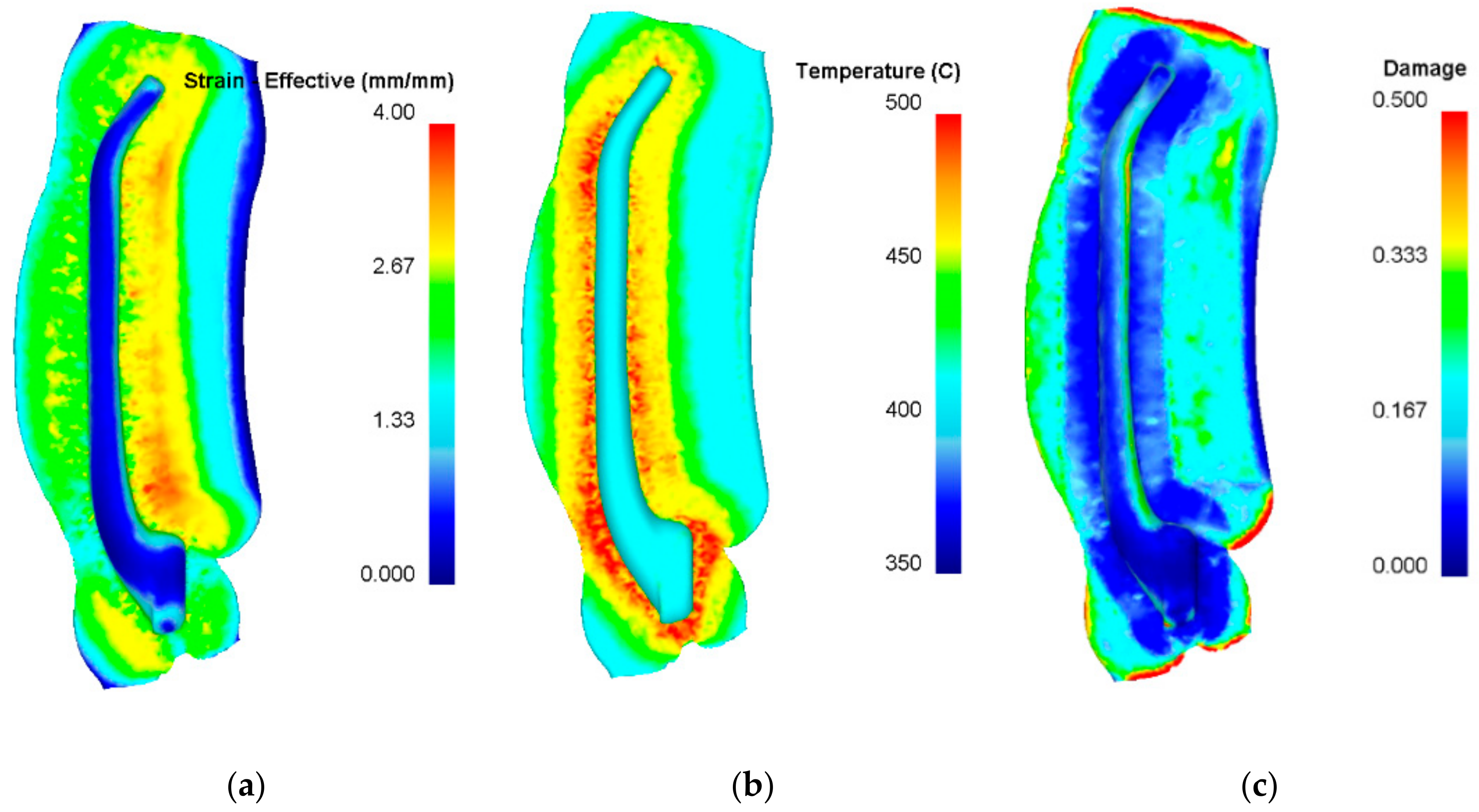
- Analyse the distribution of temperature and effective strain in the forged part;
- Identify the regions of the forging that are most prone to crack formation;
- Examine the flow of material in individual operations, predominantly in terms of potential underfill, overlap and other shape defects;
- Determine stroke energy (hammer forging) and forming force (press forging) in order to select the most suitable forging machine.
- σ—flow stress, MPa;
- ε—strain;
- —strain rate, s−1;
- T—temperature, °C.
- σ1—maximum principal stress;
- σe—equivalent stress;
- ε—strain;
- C—integral value.
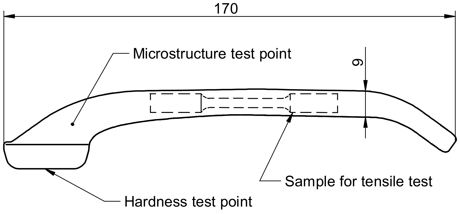
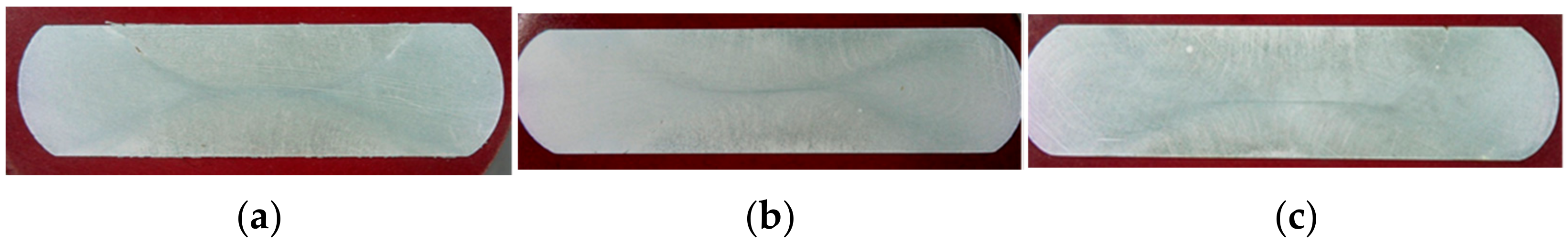
2.3. Stage 3
- Determination of strength properties via static tensile testing in room temperature;
- Measurement of Brinell hardness;
- Examination of the macrostructure in the longitudinal and cross sections relative to the fibre direction;
- Metallographic examination of the microstructure in the etched condition.
3. Results and Discussion
3.1. Stage 1—Upset Forging Tests
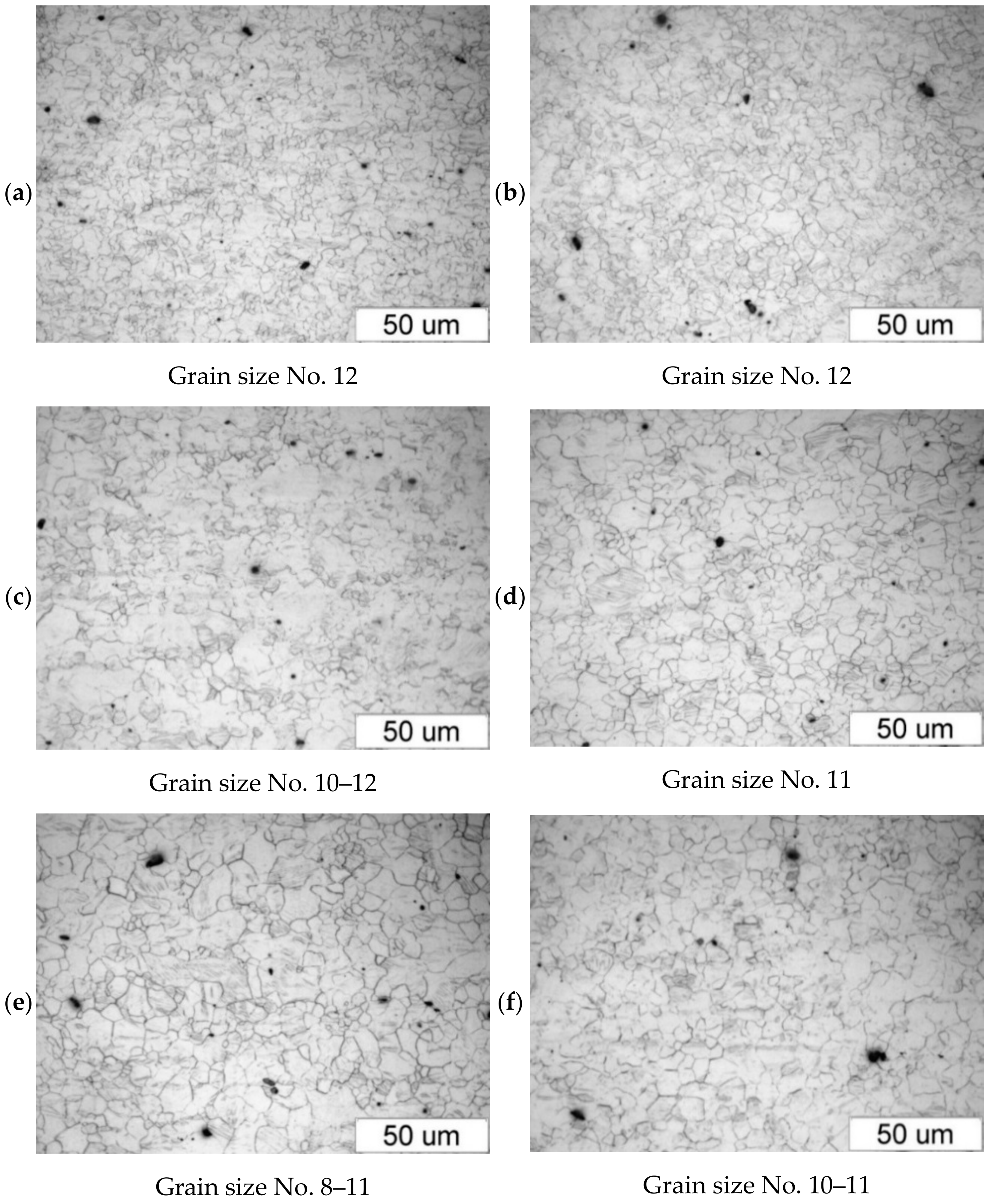
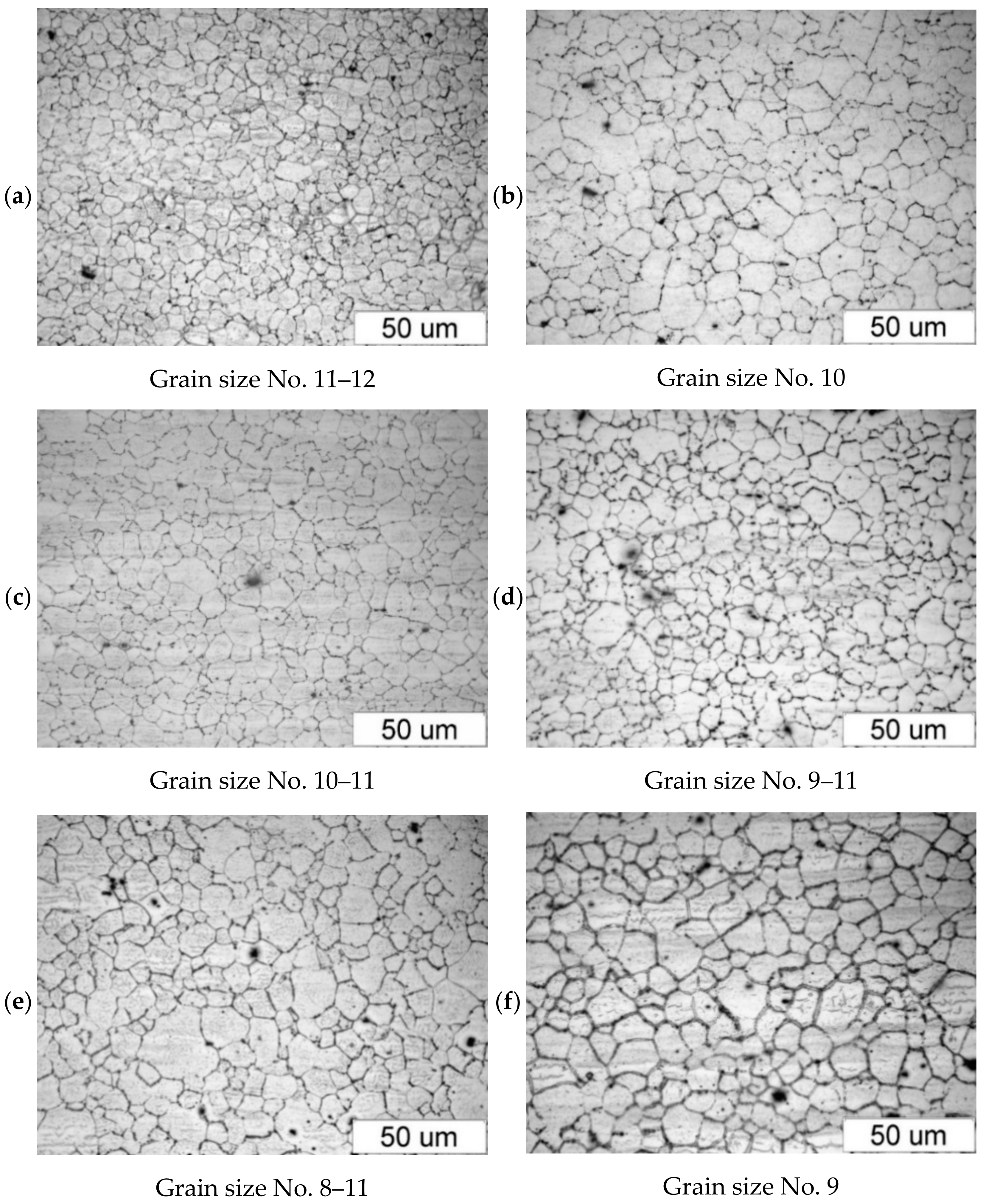
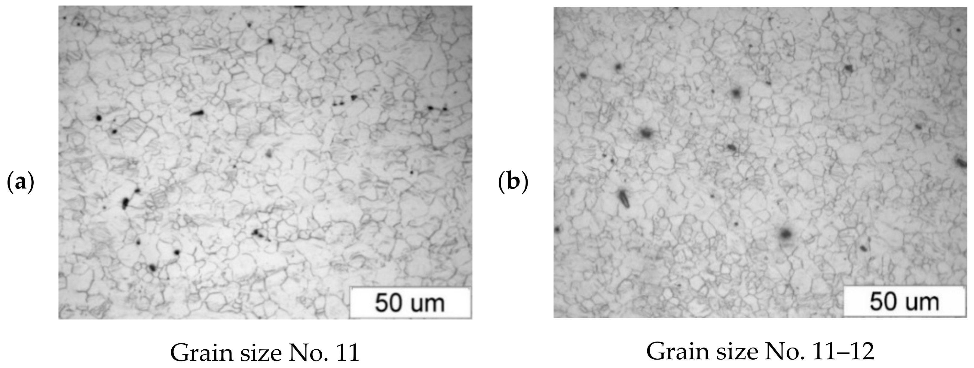
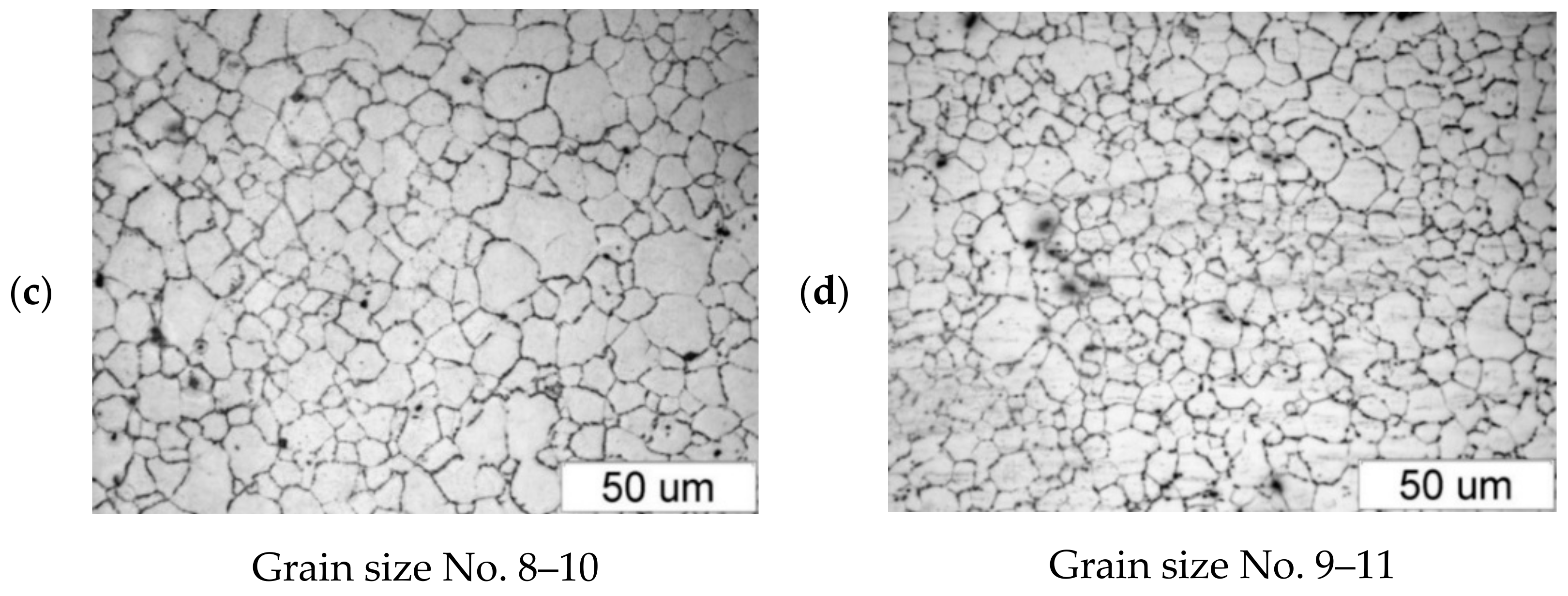
- The grain size in the AZ31B specimens corresponds to the grain size numbers 7–12;
- The grain size in the AZ61A specimens corresponds to the grain size numbers 9–12.
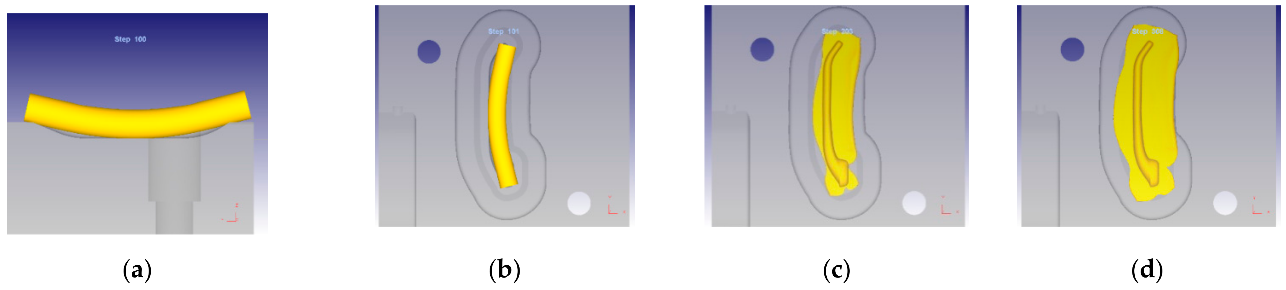
3.2. Stage 2—Numerical Modelling
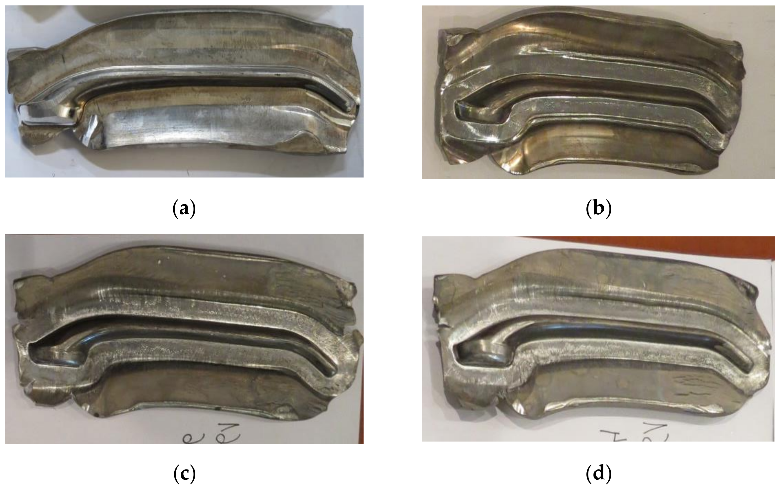
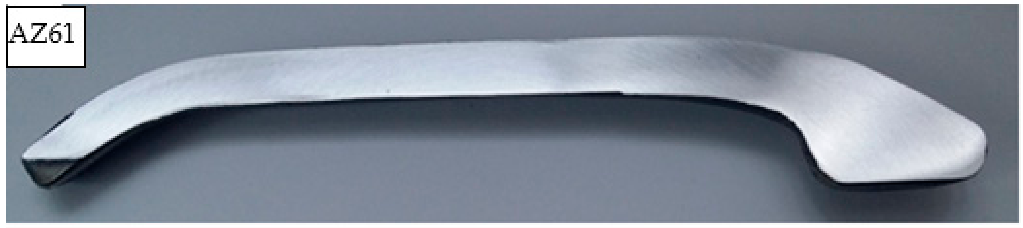
3.3. Stage 3—Experimental Tests
4. Conclusions
- It is technically feasible to obtain correctly shaped forged parts with required quality from the selected AZ magnesium alloys (with zinc and aluminium addition), using high-speed tool forging machines such as screw presses and die hammers. AZ31B alloy exhibits good workability when preheated to 410 °C and forged with the use of both machines. For the same temperature, AZ61A alloy exhibits satisfactory workability when the die forging process is conducted with a screw press; when subjected to hammer forging, the workability of this alloy is acceptable only in forging processes for simple-shape parts. What is more, to obtain correctly shaped forged parts, the tools must be preheated to 300 °C.
- Due to its low workability at high deformation speed, AZ80A alloy cannot be forged on screw presses and forging hammers, as this would lead to crack formation. AZ80A alloy parts should be forged in compliance with the guidelines presented in the specialist literature, i.e., with the use of slow hydraulic presses and tool preheating systems for ensuring near-isothermal conditions.
- The mechanical properties of the forged parts obtained with the forging hammer and screw press are similar and meet the requirements for the tested alloys. The application of stress relief annealing does not affect their mechanical properties to any significant extent. It only slightly increases the grain size.
- The results of microstructural examination have shown that the magnesium alloy specimens subjected to hammer forging are more fine-grained than those forged with the screw press. The grain in the water-cooled forged parts is slightly finer than in the air-cooled forgings.
- The fact that some magnesium alloys containing zinc and aluminium can be forged using screw presses and forging hammers is of great practical importance. The results demonstrate that die forging processes for AZ31B and AZ61A can be performed in forging plants equipped with standard forging machines, and that the use of expensive tool preheating systems is not necessary. Therefore, the proposed forging technique is more cost-effective than isothermal forging with hydraulic presses.
Author Contributions
Funding
Data Availability Statement
Conflicts of Interest
References
- Luo, A. Applications: Aerospace, automotive and other structural applications of magnesium. Chapter 8. In Fundamentals of Magnesium Alloy Metallurgy; Pekguleryuz, M., Kainer, K., Kaya, A., Eds.; Woodhead Publishing Limited: Cambridge, UK, 2013. [Google Scholar]
- Guohua, W.; Cunlong, W.; Ming, S.; Wenjiang, D. Recent developments and applications on high-performance cast magnesium rare-earth alloys. J. Magnes. Alloys 2020, in press. [Google Scholar]
- Heimann, R.B. Magnesium alloys for biomedical application: Advanced corrosion control through surface coating. Surf. Coat. Technol. 2020, in press. [Google Scholar] [CrossRef]
- Gronostajski, Z.; Kaczyński, P.; Polak, S.; Bartczak, B. Energy absorption of thin-walled profiles made of AZ31 magnesium alloy. Thin-Walled Struct. 2018, 122, 491–500. [Google Scholar] [CrossRef]
- Ngoc, S.H.; Guoxing, L. A review of recent research on bio-inspired structures and materials for energy absorption applications. Compos. Part B 2020, 181, 107496. [Google Scholar]
- Skubisz, P.; Sińczak, J.; Bednarek, S. Forgeability of Mg-Al-Zn magnesium alloys in hot and warm closed die forging. J. Mater. Process. Technol. 2006, 177, 210–213. [Google Scholar] [CrossRef]
- Nunes, R.; Abbas, I. ASM Handbook—Volume 14: Forming and Forging; ASM International: Materials Park, OH, USA, 1996. [Google Scholar]
- Dieter, G.E.; Kuhn, H.A.; Semiatin, S.L. Handbook of Workability and Process Design; ASM International: Materials Park, OH, USA, 2003. [Google Scholar]
- Gontarz, A.; Pater, Z.; Drozdowski, K. Hammer forging process of lever drop forging from AZ31 magnesium alloy. Metalurgija 2013, 52, 359–362. [Google Scholar]
- Tkocz, M. Forming of magnesium alloys. In Proceedings of the Internationale Workshop des Europäischen Zentrums für Hochfeste und Hermos Magnesiumwerkstoffe; TU Bergakademie Freiberg: Freiberg, Germany, 2010. [Google Scholar]
- Semiatin, S.L. ASM Handbook—Volume 14A: Metalworking: Bulk Forming; ASM International: Materials Park, OH, USA, 2005. [Google Scholar]
- Bauser, M.; Sauer, G.; Siegert, K. Extrusion; ASM International: Materials Park, OH, USA, 2006. [Google Scholar]
- Avedesian, M.M.; Baker, H. ASM Specialty Handbook: Magnesium and Magnesium Alloys; ASM International: Materials Park, OH, USA, 1999. [Google Scholar]
- Płonka, B.; Lech-Grega, M.; Remsak, K.; Korczak, P.; Kłyszewski, A. Die forging of high-strength magnesium alloys—The structure and mechanical properties in different heat treatment conditions. Arch. Metall. Mater. 2013, 58, 127–132. [Google Scholar] [CrossRef]
- Wang, Q.; Zhang, Z.; Zhang, X.; Li, G. New extrusion process of Mg alloy automobile wheels. Trans. Nonferr. Metals Soc. 2010, 20, 599–603. [Google Scholar] [CrossRef]
- Wang, Q.; Zhang, Z.; Zhang, X.; Yu, J. Precision forging technologies for magnesium alloy bracket and wheel. Trans. Nonferr. Metals Soc. 2008, 18, 205–208. [Google Scholar] [CrossRef]
- Juan, L.; Zhenshan, C. Hot forging process design and parameters determination of magnesium alloy AZ31B spur bevel gear. J. Mater. Process. Technol. 2009, 209, 5871–5880. [Google Scholar]
- Shan, D.; Xu, W.; Han, X.; Huang, X. Study on isothermal precision forging process of rare earth intensifying magnesium alloy. Mater. Sci. Eng. B 2012, 177, 1698–1702. [Google Scholar] [CrossRef]
- Henn, Y.; Fein, A. Project MagForming—Development of New Magnesium Forming Technologies for the Aeronautics Industry. Publishable Final Activity Report; Palbam: En Charod Ichud, Israel, 2010. [Google Scholar]
- Hombergsmeier, E.; Fein, A. MagForming—Development of new magnesium forming technologies for the aeronautic industry. In Proceedings of the Sixth European Aeronautics Days—Aerodays 2011, Madrid, Spain, 31 March–1 April 2011. [Google Scholar]
- Dziubińska, A.; Gontarz, A. Forming of flat parts with ribs from magnesium alloy. Aircr. Eng. Aerosp. Technol. 2014, 86, 1–10. [Google Scholar]
- Dziubińska, A.; Gontarz, A. Limiting phenomena in a new forming process for two-rib plates. Metalurgija 2015, 54, 555–558. [Google Scholar]
- Behrens, B.A.; Schmidt, I. Improving the properties of forged magnesium parts by optimized process parameters. J. Mater. Process. Technol. 2007, 187–188, 761–765. [Google Scholar] [CrossRef]
- Rao, K.; Prasad, Y.; Suresh, K. Materials modeling and simulation of isothermal forging of rolled AZ31B magnesium alloy: Anisotropy of flow. Mater. Des. 2011, 32, 2545–2553. [Google Scholar] [CrossRef]
- Su, Z.; Wan, L.; Sun, C.; Cai, Y.; Yang, D. Hot deformation behavior of AZ80 magnesium alloy towards optimization of its hot workability. Mater. Charact. 2016, 122, 90–97. [Google Scholar] [CrossRef]
- Papenberg, N.P.; Gneiger, S.; Weißensteiner, I.; Uggowitzer, P.J.; Pogatscher, S. Mg-Alloys for forging applications—A review. Materials 2020, 13, 985. [Google Scholar] [CrossRef] [Green Version]
- Madaj, M.; Greger, M.; Karas, V. Magnesium-alloy die forgings for automotive applications. Mater. Technol. 2015, 49, 267–273. [Google Scholar] [CrossRef]
- Graf, M.; Ullmann, M.; Kawalla, R. Property-oriented production of forged magnesium components. Mater. Today Proc. 2015, 2, 76–84. [Google Scholar] [CrossRef]
- Kápustová, M.; Bílik, J. The rationalization of production of magnesium alloy drop forgings using FEM simulation regarding forging process. Tehnički Vjesnik 2017, 24, 1323–1329. [Google Scholar]
- He, H.; Huang, S.; Yi, Y.; Guo, W. Simulation and experimental research on isothermal forging with semi-closed die and multi-stage-change speed of large AZ80 magnesium alloy support beam. J. Mater. Process. Technol. 2017, 246, 198–204. [Google Scholar] [CrossRef]
- Yuan, L.; Zhao, Z.; Shi, W.; Xu, F.; Shan, D. Isothermal forming of the large-size AZ80A magnesium alloy forging with high mechanical properties. Int. J. Adv. Manuf. Technol. 2015, 78, 2037–2047. [Google Scholar] [CrossRef]
- Chen, Q.; Zhang, X.; Lin, J.; Zhan, H.; Zhao, Z.; Xie, Z.; Yuan, B. Isothermal closed-die forming process of magnesium alloy upper receiver: Numerical simulation and experiments. Int. J. Adv. Manuf. Technol. 2019, 102, 685–694. [Google Scholar] [CrossRef]
- Suresh, K.; Rao, K.; Prasad, Y.; Hort, N.; Dieringa, H. Hot forging of Mg-4Al-2Ba-2Ca (ABaX422) alloy and validation of processing map. Trans. Nonferrous Met. Soc. 2018, 28, 1495–1503. [Google Scholar] [CrossRef]
- Greger, M.; Widomská, M.; Karas, V. Properties of forgings from magnesium alloys and their use in industry. In Proceedings of the 21st International Conference on Metallurgy and Materials-METAL 2012, Brno, Czech Republik, 23 May–25 May 2012. [Google Scholar]
- ASTM E112-10–Standard Test Methods for Determining Average Grain Size; ASTM International: West Conshohocken, PA, USA, 2010.
- Agnew, S.R.; Duygulu, O. Plastic anisotropy and the role of non-basal slip in magnesium alloy AZ31B. Int. J. Plast. 2005, 21, 1161–1193. [Google Scholar] [CrossRef]
- Costa Mattos, H.S.; Minak, G.; Di Gioacchino, F.; Solda, A. Modeling the superplastic behavior of Mg alloy sheets under tension using a continuum damage theory. Mater. Des. 2009, 30, 1674–1679. [Google Scholar] [CrossRef]
- Zhang, K.F.; Yin, D.L.; Wu, D.Z. Formability of AZ31 magnesium alloy sheets at warm working conditions. Int. J. Mach. Tool. Manu. 2006, 46, 1276–1280. [Google Scholar] [CrossRef]
- Niu, J.G.; Zhang, X.; Hang, Z.M.; Li, B.C. Influence on the microstructure and properties of AZ61 magnesium alloy at warm deformation. J. Mater. Process. Technol. 2007, 187–188, 780–782. [Google Scholar] [CrossRef]
- Połuchin, P.I.; Gun, G.J.; Gałkin, A.K. Soprotivlenije Plasticzeskoj Dieformacji Mietallov i Splavov; Spravocznik; Mietallurgija: Moskva, Russia, 1983. (In Russian) [Google Scholar]
- Gontarz, A.; Dziubińska, A.; Okoń, Ł. Determination of friction coefficients at elevated temperatures for some Al, Mg and Ti alloys. Arch. Metall. Mater. 2011, 56, 379–384. [Google Scholar] [CrossRef] [Green Version]
- Cockcroft, M.G.; Latham, D.J. Ductility and workability of metals. J. Inst. Metals 1968, 96, 33–39. [Google Scholar]
- Shim, K.H.; Lee, S.K.; Kang, B.S.; Hwang, S.M. Investigation on blanking of thin sheet metal using the ductile fracture criterion and its experimental verification. J. Mater. Process. Technol. 2004, 155–156, 1935–1942. [Google Scholar] [CrossRef]
- Gontarz, A.; Drozdowski, K.; Dziubińska, A.; Winiarski, G. A study of a new screw press forging process for producing aircraft drop forgings made of magnesium alloy AZ61A. Aircr. Eng. Aerosp. Tec. 2018, 90, 559–565. [Google Scholar] [CrossRef]
- Gontarz, A. Theoretical and experimental research of hammer forging process of RIM from AZ31 magnesium alloy. Metalurgija 2014, 53, 645–648. [Google Scholar]


| Material | Al | Zn | Mn | Fe | Si | Cu | Ni | Mg |
|---|---|---|---|---|---|---|---|---|
| AZ31B | 2.5–3.5 | 0.6–1.4 | 0.2–1.0 | max 0.005 | max 0.10 | max 0.05 | max 0.005 | rest |
| AZ61A | 5.8–7.2 | 0.4–1.5 | 0.15–0.5 | max 0.005 | max 0.10 | max 0.05 | max 0.005 | rest |
| AZ80A | 7.8–9.2 | 0.2–0.8 | 0.12–0.5 | max 0.005 | max 0.10 | max 0.05 | max 0.005 | rest |
| Grain Size No. | 5.0 | 6.0 | 7.0 | 8.0 | 9.0 | 10.0 | 11.0 | 12.0 | 13.0 |
| Average Diameter, μm | 63.5 | 44.9 | 31.8 | 22.5 | 15.9 | 11.2 | 7.9 | 5.6 | 4.0 |
| Mechanical Properties | ||||
|---|---|---|---|---|
| Material | Yield Strength, MPa | Ultimate Tensile Strength, MPa | Elongation, % | Brinell Hardness |
| AZ31B | 150 | 240 | 9.0 | 45 |
| AZ61A | 165 | 275 | 7.0 | 50 |
| Forging Machine | 350 | Temperature, °C 410 | 450 |
|---|---|---|---|
| Screw press |  |  |  |
| Forging hammer |  |  |  |
| Forging Machine | 350 | Temperature, °C 410 | 450 |
|---|---|---|---|
| Screw press |  |  |  |
| Forging hammer |  |  |  |
| Forging Machine | 350 | Temperature, °C 410 | 450 |
|---|---|---|---|
| Screw press |  |  |  |
| Forging hammer |  |  |  |
| Temperature °C | Cooling Method | Hardness HB | |||
|---|---|---|---|---|---|
| AZ31B | AZ61A | ||||
| Press | Hammer | Press | Hammer | ||
| 350 | Air | 62.6 | 59.5 | 65.2 | 61.2 |
| Water | 65.5 | 64.5 | 64.6 | 59.1 | |
| 410 | Air | 60.5 | 59.3 | 63.2 | 60.0 |
| Water | 58.9 | 60.4 | 67.6 | 61.9 | |
| 450 | Air | 60.1 | 58.3 | 61.2 | 56.8 |
| Water | 60.9 | 59.4 | 59.0 | 60.3 | |
| Billet | – | 56.2 | 57.8 | ||
| Properties | Heat Treatment | Mechanical Properties | |||
|---|---|---|---|---|---|
| AZ31B | AZ61A | ||||
| Press | Hammer | Press | Hammer | ||
| YS, MPa | No | 229 | 217 | 218 | 206 |
| SRA | 218 | 222 | 220 | 210 | |
| TS, MPa | No | 280 | 264 | 305 | 292 |
| SRA | 272 | 271 | 302 | 292 | |
| E, % | No | 14.4 | 14.8 | 12.0 | 14.4 |
| SRA | 14.0 | 15.2 | 10.0 | 10.0 | |
| HB | No | 57.2 | 53.2 | 58.3 | 52.3 |
| SRA | 54.3 | 52.6 | 56.8 | 52.0 | |
| Heat Treatment | ||
|---|---|---|
| Alloy | No Heat Treatment | Stress Relief Annealing |
| AZ31B |  Grain size No. 9–10 |  Grain size No. 8–9 |
| AZ61A |  Grain size No. 8–9 |  Grain size No. 7–8 |
| Heat Treatment | ||
|---|---|---|
| Alloy | No Heat Treatment | Stress Relief Annealing |
| AZ31B |  Grain size No. 8–10 |  Grain size No. 7–9 |
| AZ61A |  Grain size No. 8–9 |  Grain size No. 6–8 |
| Press | Hammer | |
|---|---|---|
| AZ31B |  |  |
| AZ61A |  |  |
Publisher’s Note: MDPI stays neutral with regard to jurisdictional claims in published maps and institutional affiliations. |
© 2020 by the authors. Licensee MDPI, Basel, Switzerland. This article is an open access article distributed under the terms and conditions of the Creative Commons Attribution (CC BY) license (http://creativecommons.org/licenses/by/4.0/).
Share and Cite
Gontarz, A.; Drozdowski, K.; Michalczyk, J.; Wiewiórowska, S.; Pater, Z.; Tomczak, J.; Samołyk, G.; Winiarski, G.; Surdacki, P. Forging of Mg-Al-Zn Magnesium Alloys on Screw Press and Forging Hammer. Materials 2021, 14, 32. https://0-doi-org.brum.beds.ac.uk/10.3390/ma14010032
Gontarz A, Drozdowski K, Michalczyk J, Wiewiórowska S, Pater Z, Tomczak J, Samołyk G, Winiarski G, Surdacki P. Forging of Mg-Al-Zn Magnesium Alloys on Screw Press and Forging Hammer. Materials. 2021; 14(1):32. https://0-doi-org.brum.beds.ac.uk/10.3390/ma14010032
Chicago/Turabian StyleGontarz, Andrzej, Krzysztof Drozdowski, Jacek Michalczyk, Sylwia Wiewiórowska, Zbigniew Pater, Janusz Tomczak, Grzegorz Samołyk, Grzegorz Winiarski, and Piotr Surdacki. 2021. "Forging of Mg-Al-Zn Magnesium Alloys on Screw Press and Forging Hammer" Materials 14, no. 1: 32. https://0-doi-org.brum.beds.ac.uk/10.3390/ma14010032