Article

Novel Triarylamine-Based Hole Transport Materials: Synthesis, Characterization and Computational Investigation

1
Chemistry Department, Faculty of Science, King Abdulaziz University, Jeddah 21589, Saudi Arabia
2
Chemistry Department, Faculty of Science, University of Jeddah, Jeddah 21589, Saudi Arabia
3
Dyeing, Printing and Textile Auxiliaries Department, Textile Research Division, National Research Centre, Dokki, Cairo 12622, Egypt
4
College of Science, Northeast Forestry University, Harbin 150040, China
5
Center of Excellence for Advanced Materials Research, King Abdulaziz University, Jeddah 21589, Saudi Arabia
*
Authors to whom correspondence should be addressed.
Submission received: 19 April 2021 / Revised: 16 May 2021 / Accepted: 2 June 2021 / Published: 7 June 2021
(This article belongs to the Special Issue New Hole Transporting Materials for Perovskite Solar Cells)

Abstract

:
Three novel triarylamine-based electron-rich chromophores were synthesized and fully characterized. Compounds 1 and 2 were designed with electron-rich triphenylamine skeleton bearing two and four decyloxy groups namely, 3,4-bis(decyloxy)-N,N-diphenylaniline and N-(3,4-bis(decyloxy)phenyl)-3,4-bis(decyloxy)-N-phenylaniline, respectively. The well-known electron-rich phenothiazine was introduced to diphenylamine moiety through a thiazole ring to form N,N-bis(3,4-bis(decyloxy)phenyl)-5-(10H-phenothiazin-2-yl)thiazol-2-amine (Compound 3). These three novel compounds were fully characterized and their UV–vis absorption indicated their transparency as a favorable property for hole transport materials (HTMs) suitable for perovskite solar cells. Cyclic voltammetry measurements revealed that the HOMO energy levels were in the range 5.00–5.16 eV for all compounds, indicating their suitability with the HOMO energy level of the perovskite photosensitizer. Density functional theory (DFT) and time-dependent DFT (TD-DFT) have been used to investigate the possibility of the synthesized compounds to be utilized as HTMs for perovskite solar cells (PSCs). The computational investigation revealed that the hole mobility of Compound 1 was 1.08 × 10⁻² cm2 V−1 s−1, and the substitution with two additional dialkoxy groups on the second phenyl ring as represented by Compound 2 significantly boosted the hole mobility to reach the value 4.21 × 10⁻² cm2 V−1 s−1. On the other hand, Compound 3, in which the third phenyl group was replaced by a thiazole-based phenothiazine, the value of hole mobility decreased to reach 5.93 × 10⁻⁵ cm2 V−1 s−1. The overall results indicate that these three novel compounds could be promising HTMs for perovskite solar cells.

Graphical Abstract

1. Introduction

Hole transport materials (HTMs) represent the type of organic electron-rich compounds with a sufficient length of an extended π-conjugated system having reasonable planarity to enhance its role in transporting holes from the adsorbent to cathode in organic electronic devices [1]. The ideal skeleton of an HTM consists of a central aromatic core linked to one or more than one electron-rich terminal moieties. Effective HTMs must have several properties such as low cost, good stability, infinite variety, environmental friendless, solution-processability, mechanical flexibility, tenability of electronic characteristics and easy fabrication [2,3]. HTMs represent fundamental building blocks for perovskite solar cells owing to its role in accelerating and increasing the hole extraction from the perovskite material (methylammonium lead halides (CH3NH3PbX3, where X=Cl, Br, or I) to conduct holes to the cathode [4,5,6]. To generate a sufficient driving force for hole extraction in PSCs, the highest occupied molecular orbital (HOMO) level of efficient HTMs must be higher than the valence band (VB) of perovskite (i.e., the absolute value of HOMO level of HTMs must be lower than the absolute value of the VB of perovskite).
Tuning energy levels of HTMs, especially the HOMO level, can be achieved by modifying HTMs molecular structures to maximize the photovoltaic performance of PSCs [7]. Numerous studies have been done to fulfill this issue using different techniques such as: structural tuning [8,9,10,11], changing numbers and positions of attached methoxy groups [12,13], conjugation with more electron-donating moieties [14,15,16], replacing the core of spiro-OMeTAD with other electron-rich cores [17,18], attaching aromatic groups onto their peripheral positions [19,20], binary HTMs blending [21], etc. Fabrication of the first highly efficient PSC was accomplished using the common spiro-OMeTAD as an HTM producing high power conversion efficiency (PCE) > 20%. Nevertheless, the high cost, multistep synthesis process and poor device stability related to spiro-OMeTAD hindered its practical application and required more efforts to design new HTMs [7]. On the other hand, computational chemistry is capable of providing profitable insights to predict the molecular electronic structures and optical properties of newly designed molecules and its suitability as HTMs for PSCs [22,23,24,25].
The triarylamine core has proven great potential as a candidate for constructing optoelectronics owing to its three-dimensional structure that would hamper molecular aggregation and its beneficial high electron density that can be tuned by structural modification according to the need of the application [26,27]. Therefore, it was envisioned to design and synthesize different triarylamine derivatives containing two and four ortho-alkoxy long chains, with phenyl or phenothiazinyl moieties. The newly synthesized triarylamine derivatives were fully characterized and their optoelectronic computation as HTMs were also investigated. Herein, we reported the synthesis, characterization, optoelectronic properties and computational investigation of novel triarylamine-based HTMs for PSCs.

2. Experimental

2.1. General

All solvents were purchased from Sigma-Aldrich and Fisher and used directly without further purification. All other chemicals used herein were of analytical grade and were used without further purification. Chromatographic separations were carried out on silica gel (60–120 mesh). 1H and 13C NMR spectra were recorded in CDCl3 or DMSO-d6 on a Bruker Avance 400 and 850 MHz and 100 and 213 MHz spectrometer respectively. The reported chemical shifts were against TMS. Infrared spectra (FT-IR) were performed on a Perkin-Elmer spectrum 100 FTIR spectrometer. Mass spectra were recorded on a positive ion mode on a Bruker Impact II, LC–MS/MS. Melting point apparatus SMP3 was uncorrected. UV–visible absorption spectra were recorded with a Jasco V560 spectrophotometer (Jasco International Co., Ltd., Tokyo, Japan). Cyclic voltammetric studies of the compounds were carried out in dichloromethane solution (about 10−3 M) containing 0.1 M tetrabutylammonium hexafluorophosphate (n-Bu4NPF6) as the supporting electrolyte at room temperature on an Autolab PGSTAT204 potentiostat system using a three-electrode cell under nitrogen atmosphere. The conventional three electrodes were the platinum sheet as a counter electrode, glassy carbon as the working electrode and Ag/AgCl as a reference electrode. The reference electrode potential was calibrated against ferrocene/ferrocenium (Fc/Fc+) after each voltammetry run. The solution was anodically and catholically scanned with a rate of 50 mV s−1.

2.2. Computational Methods

All calculations were performed by the Gaussian 09 program [28]. Density functional theory (DFT) [29] with B3LYP [30] functional at the 6–31G(d) basis set was used to optimize the ground-state geometries of Compounds 1–3 (see Figure S1 in Supplementary Materials) and ground-state structure and energy levels were obtained under the same framework. The conductor polarizable continuum model (CPCM) [31] was used to demonstrate the solvent effect of dichloromethane. Time-dependent DFT (TD-DFT) [32] with the CAM-B3LYP [33] and the 6–31G(d) basis set were used to acquire the corresponding absorption and fluorescence spectrum. Additionally, the optimization of excited states was done under DFT/CAM-B3LYP/6–31G(d) level. Reorganization energy was calculated using optimized charged molecules with DFT/B3LYP/6–31G(d). The face-to-face model in the HTM dimer was used to calculate the charge transfer integral. The density of states (DOS) and partial density of states (PDOS) were analyzed using GaussSum software [28,34]. Furthermore, Marcus theory was employed to study the hole mobility of the three compounds.
The absolute hardness (η) was used to estimate the stability of cells using the following equation [35]:
η = I P E A 2
The fluorescence lifetime τ1 can be calculated by the speed of light c, oscillator strength f and fluorescence energy E [36]:
τ 1 = a c 3 u 2 2 f E 2
The excited-state lifetime τ2 can be calculated by the oscillator strength f and the vertical excitation energy E [37]:
τ 2 = 1.499 f E 2
The reorganization energy (λh/e) refers to the energy change of the system, which is caused by the structural relaxation after the gain or loss of electrons [38,39]. It can be calculated by:
λ h / e = ( E 0 ± E ± ) + ( E ± 0 E 0 )
where   E 0 + ( E 0 ) is the energy of the neutral molecule under the cation (anion) and E + 0   ( E 0 ) is the energy of cationic (anionic) molecule under the neutral state, E +   ( E ) represents the optimized energy under the cation (anion) and E 0 is the ground-state energy of the neutral molecule.
When the dimer configuration is completely parallel to the face-to-face transport configuration, the charge transfer integral (Vh/e) can be considered as the half of difference of energy between HOMO (LUMO+1) and HOMO−1 (LUMO) of two adjacent neutral dimers. At this time, the error of the calculated charge transfer integral is 0%. So, the charge transfer integral (Vh/e) can be calculated using the following equations [40]:
V h = E H O M O E H O M O 1 2
V e = E L U M O + 1 E L U M O 2
where E means the corresponding orbital energy. Marcus theory was used to calculate the charge hopping rate [41]:
k h / e = v h / e 2 π λ h / e k B T exp ( λ h / e 4 k B T )
where kB, vh/e, T and λh/e are represented as the Boltzmann constant, hole/electron transfer integral, room temperature (300 K) and hole/electron reorganization energy, respectively.
Mobility can be approximately calculated by the Einstein relation [42]:
μ = e k B T 1 2 n i r i 2 k i P i
where n is the dimensionality (n = 1) and ri is centroid to centroid distance.

2.3. Synthesis

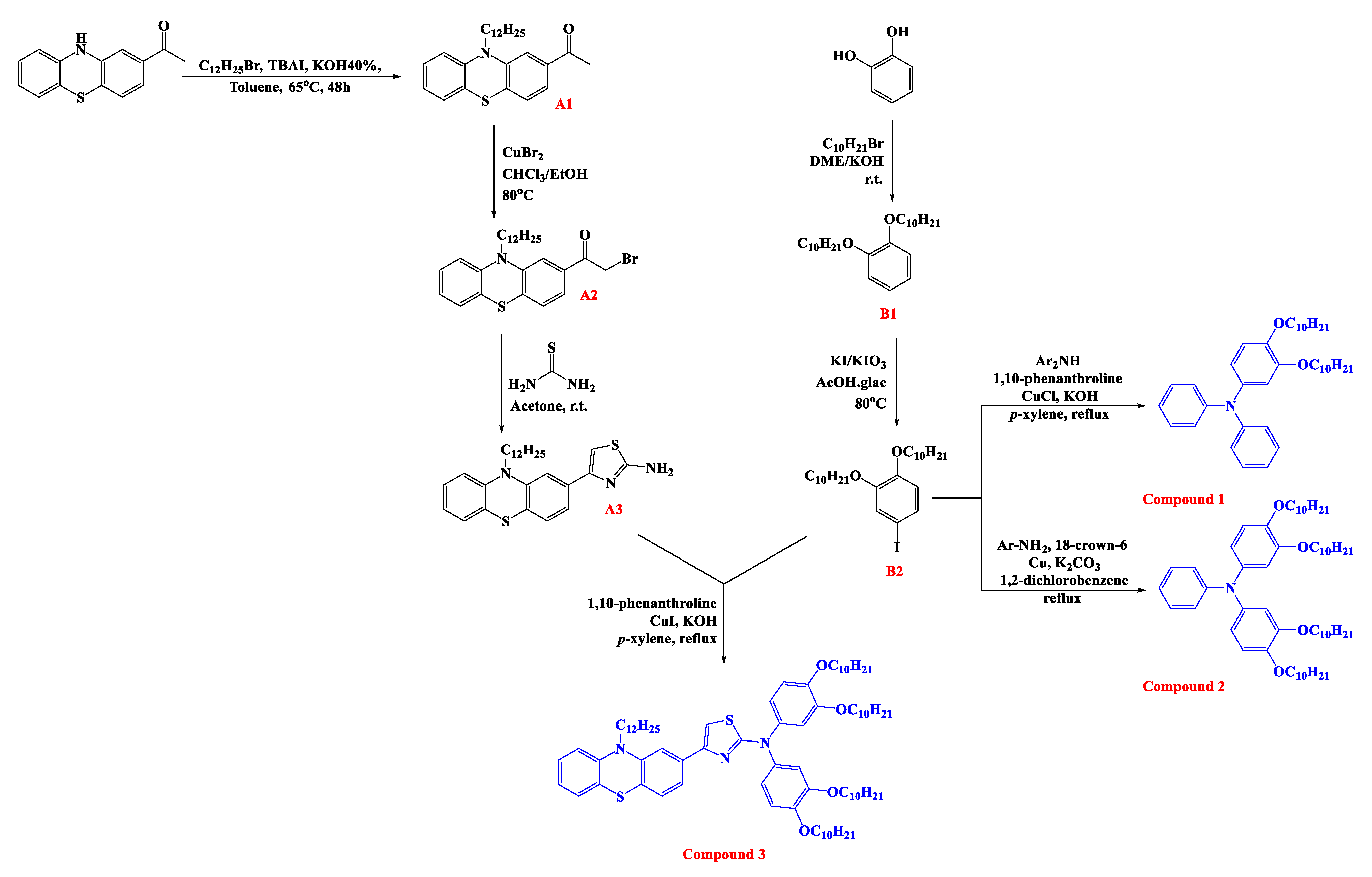
2.3.1. 1,2-Bis(decyloxy)benzene (B1)

To DMSO (2 mL) was added powdered KOH (2.2 g, 40 mmol). After stirring for 5 min, catechol (1.1 g, 10 mmol) was added, followed immediately by the decyl bromide (4.4 g, 20 mmol). Stirring was continued for 30 min after which the mixture was poured into water (200 mL) and extracted with dichloromethane (3 × 200 mL). The combined organic extracts were then dried over anhydrous sodium sulfate, filtered and the filtrate was vacuum evaporated. Recrystallization of the residue from methanol gave the product B1 in good yield (2.4 g, 61%) white crystals (mp. 39 °C). 1H NMR; (850 M Hz, CDCl3) δ: 6.87–6.89 (m, 4H, Ar-H), 3.99 (t, 4H, 2OCH2, J = 6.8 Hz), 1.81 (quint, 4H, 2CH2, J = 6.8 Hz), 1.46 (quint, 4H, 2CH2, J = 6.8 Hz), 1.36 (quint, 4H, 2CH2, J = 6.8 Hz), 1.24–1.31 (m, 20H, 10CH2), 0.88 (t, 6H, 2CH3, J = 6.8 Hz). 13C NMR; (213 M Hz, CDCl3) δ: 149.24, 120.99, 114.11, 69.28, 31.92, 29.65, 29.60, 29.45, 29.36, 29.35, 26.06, 22.69, 14.12. IR; υ cm−1: C-H aliphatic 2916, 2848, C=C stretch 1594. MS (ESI): m/z calcd for C26H47O2 391.4 [M+H]+, found 391.2.

2.3.2. 1,2-Bis(decyloxy)-4-iodobenzene (B2)

Compound (B1) (3.9 g, 10 mmol) was dissolved in boiling glacial acetic acid (50 mL), and potassium iodide (1.16 g, 7 mmol) and potassium iodate (0.85 g, 4 mmol) were added, and the mixture then boiled until iodine color disappear. The hot solution was decanted from the undissolved potassium iodate and allowed to cool slowly to room temperature. After filtration, 5% of sodium hydrogen sulphite (300 mL) was used for washing to obtain a white solid product. Then, the product was washed with plenty of water. Recrystallization from methanol afforded the product B2 in an excellent yield (4.8 g, 93%) white crystals (mp. 50 °C). 1H NMR; (850 M Hz, CDCl3) δ: 7.17 (dd, 1H, Ar-H, J = 8.5, 2.55 Hz), 7.12 (d, 1H, Ar-H, J = 1.7 Hz), 6.61 (d, 1H, Ar-H, J = 8.5 Hz), 3.95 (td, 4H, 2OCH2, J = 6.8, 1.7 Hz), 1.79 (sixtet, 4H, 2CH2, J = 6.8 Hz), 1.45 (sixtet, 4H, 2CH2, J = 7.65 Hz), 1.41 (sixtet, 4H, 2CH2, J = 7.65 Hz), 1.26–1.31 (m, 20H, 10CH2), 0.88 (overlapped-t, 6H, 2CH3, J = 6.8, 1.7 Hz). 13C NMR; (213 M Hz, CDCl3) δ: 150.12, 149.23, 129.79, 122.64, 115.71, 82.50, 69.42, 69.35, 31.91, 29.61, 29.57, 29.39, 29.37, 29.34, 29.17, 29.16, 25.97, 22.69). IR; υ cm−1: C-H aliphatic 2919, 2848, C = C stretch 1584. MS (ESI): m/z calcd for C26H46IO2 517.3 [M+H]+, found 517.3.

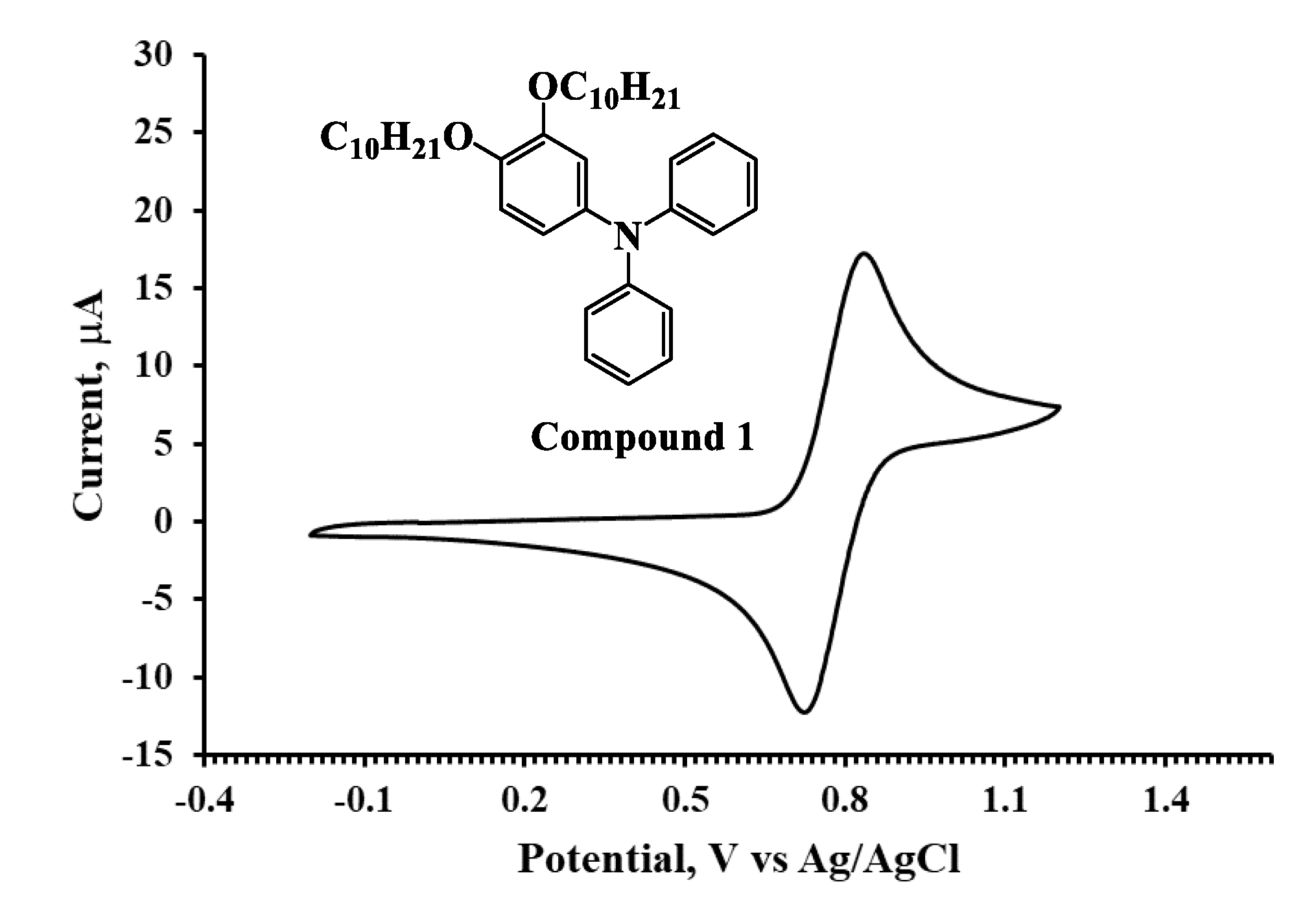
2.3.3. 3,4-Bis(decyloxy)-N,N-diphenylaniline (Compound 1)

Into a three-neck round-bottomed flask was added a mixture of diphenylamine (2.5 g, 15 mmol), compound (B2) (5.2 g, 10 mmol), 1,10-phenanthroline (5.4 g, 30 mmol) and CuI (5.7 g, 30 mmol) in 30 mL of p-xylene. The temperature was increased to 100 °C, followed by the addition of potassium hydroxide (3.4 g, 60 mmol). The mixture was refluxed with stirring for 6 h. Then, the mixture was cooled down to room temperature, and then 50 mL of toluene was poured into the mixture. The mixture was filtered after stirring, evaporated under vacuum and purified by column chromatography using petroleum ether as an eluent to give Compound 1 (2.9 g, 52%) white powder (mp. 48 °C). 1H NMR; (850 M Hz, CDCl3) δ: 7.19–7.22 (m, 4H, Ar-H), 7.04 (dd, 4H, Ar-H, J = 8.5, 0.85 Hz), 6.93–6.95 (m, 2H, Ar-H), 6.78 (d, 1H, Ar-H, J = 8.5 Hz), 6.69 (d, 1H, Ar-H, J = 2.55 Hz), 6.61 (dd, 1H, Ar-H, J = 8.5, 2.55 Hz), 3.98 (t, 2H, OCH2, J = 6.8 Hz), 3.84 (t, 2H, OCH2, J = 6.8 Hz), 1.80 (quint, 2H, CH2, J = 6.8 Hz), 1.73 (quint, 2H, CH2, J = 6.8 Hz), 1.46 (quint, 2H, CH2, J = 7.65 Hz), 1.39 (quint, 2H, CH2, J = 7.65 Hz), 1.35 (quint, 2H, CH2, J = 7.65 Hz), 1.26–1.31 (m, 22H, 11CH2), 0.88 (overlapped-t, 6H, 2CH3, J = 7.65, 2.55 Hz). 13C NMR; (213 M Hz, CDCl3) δ: 149.79, 148.07, 145.89, 141.07, 129.01, 122.93, 121.81, 118.33, 114.66, 112.36, 69.65, 69.17, 31.92, 29.65, 29.60, 29.57, 29.47, 29.44, 29.36, 29.20, 26.09, 26.06, 25.99, 22.70, 14.13. IR; υ cm−1: C-H aliphatic 2919, 2849, C=C stretch 1583. HRMS (ESI): m/z calcd for C38H56NO2 558.4311 [M+H]+, found 558.4306.

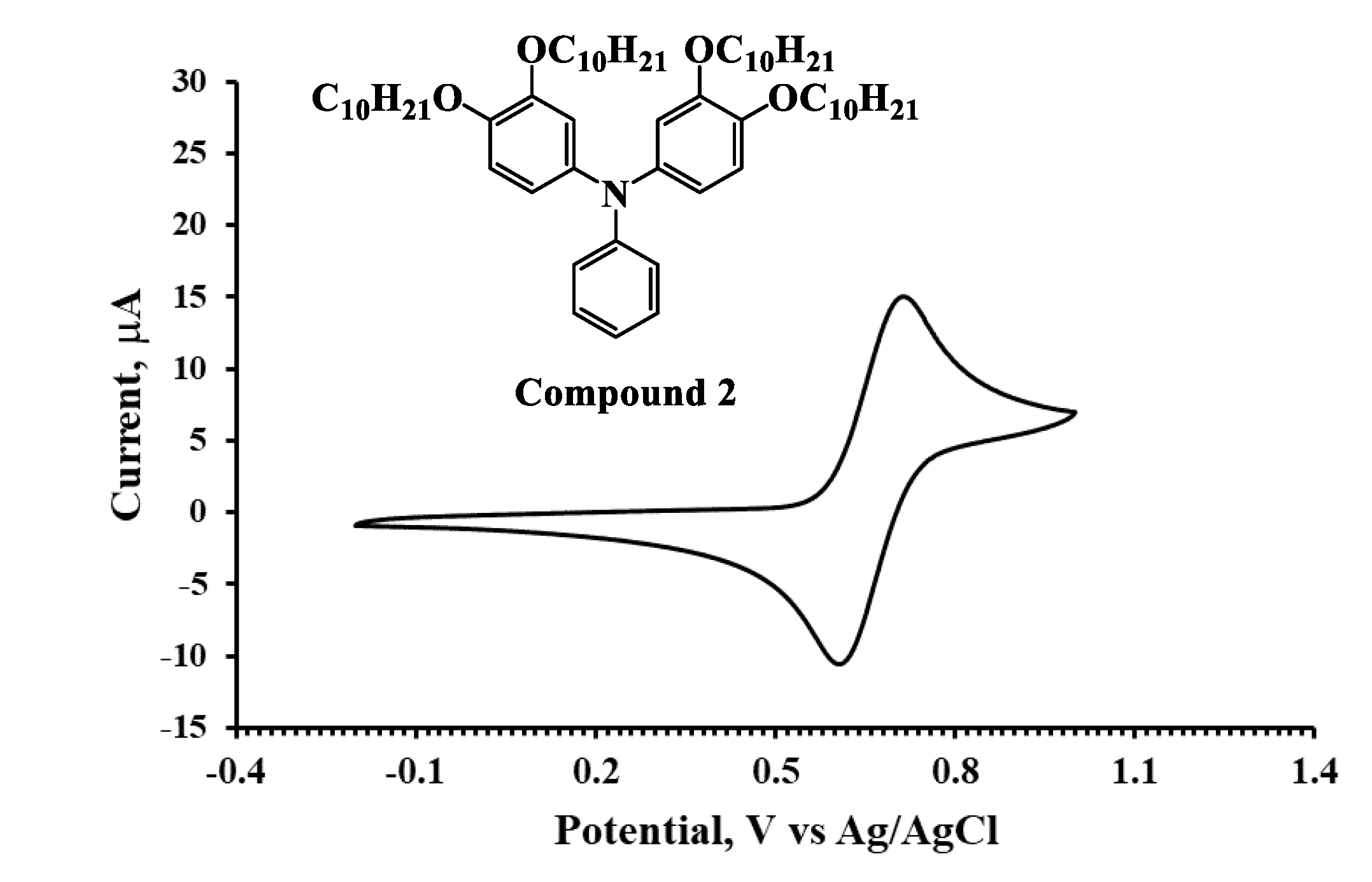
2.3.4. N-(3,4-Bis(decyloxy)phenyl)-3,4-bis(decyloxy)-N-phenylaniline (Compound 2)

A suspension of (2.3 g, 25 mmol) of aniline (38.7 g, 75 mmol) of compound (B2) and 200 mL 1, 2-dichlorobenzene were added into a three-necked flask equipped with a magnetic stirrer, a reflux condenser, and a nitrogen input tube, and then (17.9 g, 130 mmol) of anhydrous potassium carbonate and (8.3 g, 130 mmol) copper powder was added slowly. At last, a catalytic amount of 18-crown-6 was added under stirred. The reaction mixture was refluxed for 24 h and monitored by TLC. After completion of the reaction, the solvent 1,2-dichlorobenzene was evaporated under reduced pressure after the solution was cooled to room temperature. The crude product was purified by column chromatography with petroleum ether/dichloromethane (9:1) to yield Compound 2 (21.5g, 60%) of white powder (mp. 76 °C). 1H NMR; (850 M Hz, CDCl3) δ: 7.16–7.18 (m, 2H, Ar-H), 6.97 (dd, 2H, Ar-H, J = 8.5, 1.7 Hz), 6.87 (t, 1H, Ar-H, J = 7.65 Hz), 6.76 (d, 2H, Ar-H, J = 8.5 Hz), 6.67 (d, 2H, Ar-H, J = 2.55 Hz), 6.58 (dd, 2H, Ar-H, J = 8.5, 2.55 Hz), 3.96 (t, 4H, 2OCH2, J = 6.8 Hz), 3.83 (t, 4H, 2OCH2, J = 6.8 Hz), 1.79 (quint, 4H, 2CH2, J = 6.8 Hz), 1.73 (quint, 4H, 2CH2, J = 6.8 Hz), 1.46 (quint, 4H, 2CH2, J = 6.8 Hz), 1.40 (quint, 4H, 2CH2, J = 6.8 Hz), 1.25–1.37 (m, 48H, 24CH2), 0.88 (overlapped-t, 12H, 4CH3, J = 7.65 Hz). 13C NMR; (213 M Hz, CDCl3) δ: 149.68, 148.55, 145.30, 141.48, 128.83, 121.36, 120.66, 117.28, 114.71, 111.48, 69.73, 69.12, 31.92, 29.70, 29.65, 29.62, 29.60, 29.58, 29.47, 29.45, 29.36, 29.23, 26.09, 26.01, 22.69, 14.12. IR; υ cm−1: C-H aliphatic 2917, 2849, C=C stretch 1593. HRMS (ESI): m/z calcd for C58H96NO4 870.7333 [M+H]+, found 870.7339.

2.3.5. 1-(10-Dodecyl-10H-phenothiazin-2-yl)ethan-1-one (A1)

A mixture of 2-acetylphenothiazine (1.4 g, 6 mmol), alkyl iodide (3 g, 18 mmol), potassium hydroxide 40% (20 ml) and tetrabutylammonium iodide (TBAI) (0.66 g, 1.8 mmol) in 20 ml toluene was refluxed gently at 65 °C for 48 h with good stirring. After the reaction mixture was cooled to room temperature, 50 ml of water was added to the mixture by extraction with ethyl acetate (3 × 50 ml). The organic layer was washed with a saturated aqueous solution of ammonium chloride and then water. After drying the organic layer with sodium sulfate anhydrous and evaporation under reduced pressure, brown oil of the product was obtained. The product was purified by column chromatography (eluent; petroleum ether: ethyl acetate 98:2) on silica gel to give (A1) (1.6 g, 67%) as a yellow oil. 1H NMR; (850 M Hz, cdcl3) δ: 7.45 (d, 1H, Ar-H, J = 7.65 Hz), 7.42 (s, 1H, Ar-H), 7.15–7.17 (m, 2H, Ar-H), 7.09 (d, 1H, Ar-H, J = 7.65 Hz), 6.92 (t, 1H, Ar-H, J = 7.65 Hz), 6.86 (d, 1H, Ar-H, J = 8.5 Hz), 3.87 (t, 2H, NCH2, J = 6.8 Hz), 2.56 (s, 3H, CH3), 1.79 (quint, 2H, CH2, J = 7.65 Hz), 1.43 (quint, 2H, CH2, J = 7.65 Hz), 1.23–1.32 (m, 16H, 8CH2), 0.88 (t, 3H, CH3, J = 6.8 Hz). 13C NMR; (213 M Hz, cdcl3) δ: 197.47, 145.56, 144.56, 136.22, 132.03, 127.60, 127.40, 126.95, 123.59, 122.93, 122.68, 115.71, 113.89, 47.51, 31.91, 29.62, 29.53, 29.51, 39.34, 29.22, 26.90, 26.68, 26.59, 22.69, 14.13. IR; υ cm−1: C-H aliphatic 2922, 2852, C=O 1681, C=C stretch 1591, 1558. MS (ESI): m/z calcd for C26H36NOS 410.3 [M+H]+, found 410.2.

2.3.6. 2-Bromo-1-(10-dodecyl-10H-phenothiazin-2-yl)ethan-1-one (A2)

Copper (II) bromide (2.5 g, 11 mmol) was placed in a round-bottom flask fitted with a reflux condenser, and ethyl acetate (20 mL) was added and brought to reflux. Compound (A1) (2.4 g, 10 mmol) was dissolved in hot chloroform (20 mL) and added to the flask. The resulting reaction mixture was gently refluxed at 60 °C with vigorous stirring until the disappearance of all black solids (30 min). After cooling and removal of the copper(1)bromide by filtration, the solvents were removed from the filtrate under reduced pressure. The residue was dissolved in 50 mL of chloroform then washed 3 times with sodium hydroxide solution 1% and then water. After drying the organic layer with sodium sulfate anhydrous and evaporation under reduced pressure, an orange oil was obtained. The product was purified by column chromatography (eluent; petroleum ether:dichloromethane; 7:3) on silica gel to give (A2) (4.8g, 98%) as an orange oil. 1H NMR; (850 M Hz, CDCl3) δ: 7.44 (dd, 1H, Ar-H, J = 7.65, 1.7 Hz), 7.42 (d, 1H, Ar-H, J = 1.7 Hz), 7.16–7.18 (m, 2H, Ar-H), 7.09 (dd, 1H, Ar-H, J = 7.65, 1.7 Hz), 6.93 (td, 1H, Ar-H, J = 7.65, 0.85 Hz), 6.86 (d, 1H, Ar-H, J = 7.65 Hz), 4.39 (s, 2H, CH2Br), 3.87 (t, 2H, NCH2, J = 7.65 Hz), 1.79 (quint, 2H, CH2, J = 7.65 Hz), 1.43 (quint, 2H, CH2, J = 7.65 Hz), 1.24–1.33 (m, 16H, 8CH2), 0.88 (t, 3H, CH3, J = 6.8 Hz). 13C NMR; (213 M Hz, CDCl3) δ: 190.76, 145.71, 144.31, 133.38, 132.91, 127.74, 127.41, 127.06, 123.23, 123.15, 122.85, 115.74, 114.58, 47.62, 31.92, 30.64, 29.71, 29.63, 29.54, 29.52, 29.35, 29.22, 26.90, 26.61, 22.70, 14.14. IR; υ cm−1: C-H aliphatic 2922, 2852, C=O 1676, C=C stretch 1591, 1558. MS (ESI): m/z calcd for C26H35BrNOS 488.2 [M+H]+, found 488.1.

2.3.7. 5-(10-Dodecyl-10H-phenothiazin-2-yl)thiazol-2-amine (A3)

A mixture of thiourea (0.5 g, 7 mmol) and compound (A2) (3.4 g, 7 mmol) in 70 mL acetone was stirred overnight at room temperature and filtered to afford the corresponding hydrobromide salt quantitatively. Then, the salt was treated with 5% ammonia solution with stirring and filtered to give the desired thiazole product A3 (3.16g, 99%) as a pale-yellow powder (mp. 80 °C). 1H NMR; (850 M Hz, CDCl3) δ: 7.32 (d, 1H, Ar-H, J = 1.7 Hz), 7.27 (dd, 1H, Ar-H, J = 8.5, 1.7 Hz), 7.12–7.15 (m, 2H, Ar-H), 7.09 (d, 1H, Ar-H, J = 8.5 Hz), 6.89 (td, 1H, Ar-H, J = 6.8, 0.85 Hz), 6.85 (dd, 1H, Ar-H, J = 8.5, 0.85 Hz), 6.66 (s, 1H, Ar-H), 5.09 (s, 2H, NH2), 3.89 (t, 2H, NCH2, J = 6.8 Hz), 1.81 (quint, 2H, J = 7.65 Hz), 1.43 (quint, 2H, CH2, J = 6.8 Hz), 1.22–1.32 (m, 16H, 8CH2), 0.87 (t, 3H, CH3, J = 6.8 Hz). 13C NMR; (213 M Hz, CDCl3) δ: 167.08, 151.05, 145.76, 145.13, 133.93, 127.37, 127.35, 127.16, 124.90, 124.50, 122.29, 119.91, 115.58, 113.33, 102.65, 47.44, 31.91, 29.64, 29.63, 29.56, 29.53, 29.34, 29.26, 26.96, 26.94, 22.69, 14.13. IR; υ cm−1: N-H 3281, 3126, C-H aliphatic 2914, 2849, C=N stretch 1705, C=C stretch 1532. MS (ESI): m/z calcd for C27H36N3S2 466.2 [M+H]+, found 466.2.

2.3.8. N,N-Bis(3,4-bis(decyloxy)phenyl)-5-(10-dodecyl-10H-phenothiazin-2-yl)thiazol-2-amine (Compound 3)

Into a three-neck round-bottomed flask was added a mixture of compound (A3) (2.3 g, 5 mmol), compound (B2) (5.2 g, 10 mmol), 1,10-phenanthroline (5.4 g, 30 mmol) and CuI (5.7 g, 30 mmol) in 30 mL of p-xylene. The temperature was increased to 100 °C, followed by the addition of potassium hydroxide (3.4 g, 60 mmol). The mixture was refluxed with stirring for 6 h. Then, the mixture was cooled down to room temperature, and then 50 mL of toluene was poured into the mixture. The mixture was filtered after stirring, evaporated under vacuum and purified by column chromatography using petroleum ether and dichloromethane 8:2 as an eluent to afford Compound 3 (3 g, 49%) as a yellow semisolid. 1H NMR; (850 M Hz, CDCl3) δ: 7.55 (d, 2H, Ar-H, J = 1.7 Hz), 7.50 (dd, 2H, Ar-H, J = 8.5, 1.7 Hz), 7.46 (s, 1H, Ar-H), 7.14–7.16 (m, 2H, Ar-H), 7.12 (dd, 1H, Ar-H, J = 7.65, 1.7 Hz), 6.98 (d, 2H, Ar-H, J = 2.55 Hz), 6.92–6.91 (m, 2H, Ar-H), 6.89 (d, 1H, Ar-H, J = 1.7 Hz), 6.87 (d, 1H, Ar-H, J = 8.5 Hz), 6.84 (d, 1H, Ar-H, J = 7.65 Hz), 4.03 (t, 4H, 2OCH2, J = 6.8 Hz), 3.89 (t, 4H, 2OCH2, J = 6.8 Hz), 3.76 (t, 2H, NCH2, J = 6.8 Hz), 1.87 (quint, 4H, 2CH2, J = 6.8 Hz), 1.75 (quint, 4H, 2CH2, J = 7.65 Hz), 1.68 (quint, 4H, 2CH2, J = 6.8 Hz), 1.51 (quint, 2H, CH2, J = 7.65 Hz), 1.42–1.19 (m, 70H, 35CH2), 0.85–0.89 (m, 15H, 3CH3). 13C NMR; (213 M Hz, CDCl3) δ: 164.20, 162.40, 149.08, 146.76, 145.61, 145.16, 138.44, 137.30, 132.31, 130.92, 128.78, 127.15, 124.73, 122.63, 120.55, 119.50, 115.57, 113.67, 69.54, 69.24, 47.04, 31.92, 29.74, 29.70, 29.68, 29.66, 29.63, 29.60, 29.59, 29.55, 29.47, 29.40, 29.36, 29.32, 29.30, 27.21, 26.74, 26.67, 26.22, 26.06, 22.65, 14.12. IR; υ cm−1: C-H aliphatic 2923, 2853, C=N stretch 1733, C=C stretch 1568. HRMS (ESI): m/z calcd for C79H124N3O4S2 1242.9033 [M+H]+, found 1242.9028.

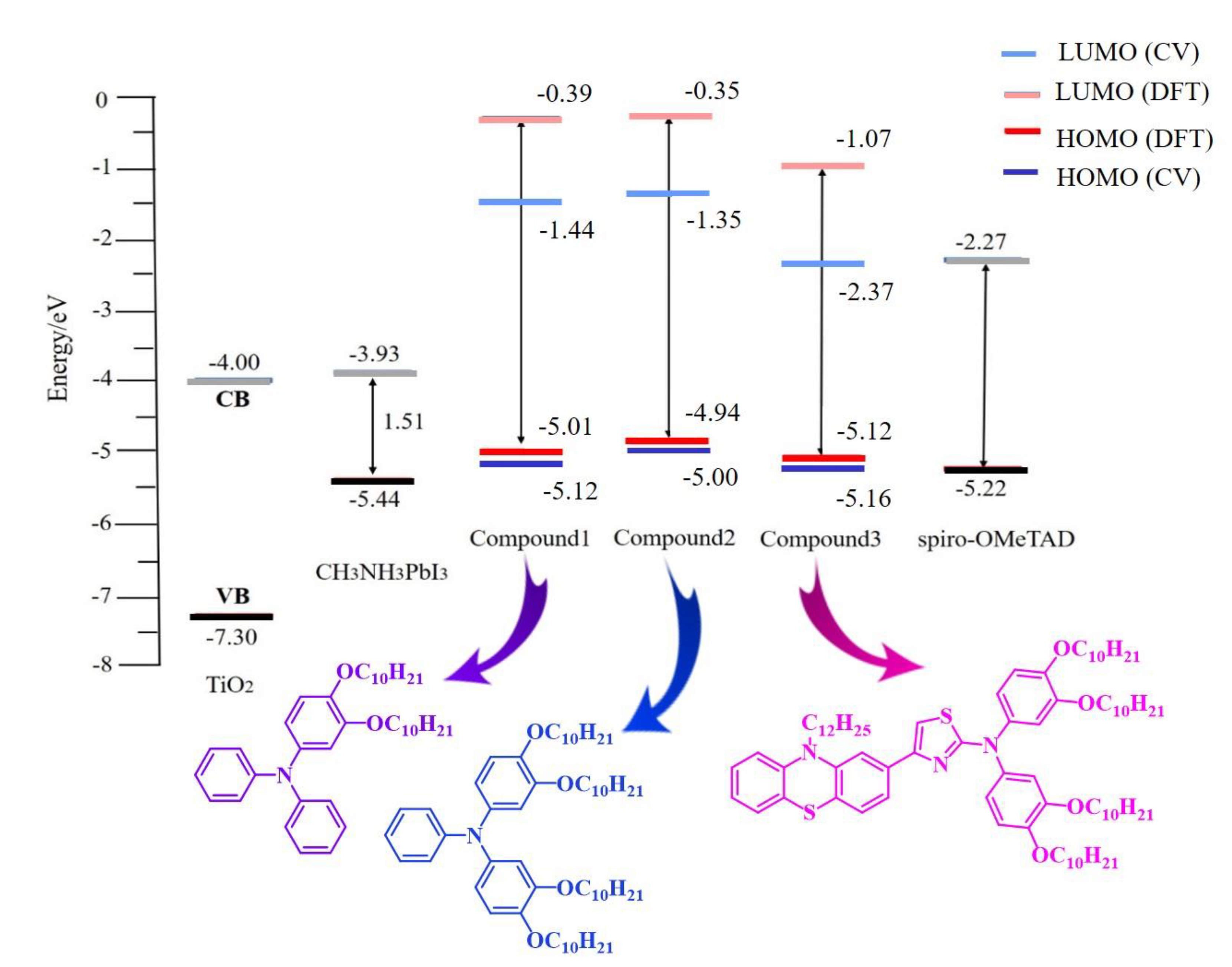
3. Result and Discussion

3.1. Synthesis

Three triarylamine derivatives Compounds 1–3 were designed and synthesized in good yields, as shown in Scheme 1. Thus, 2-acetylphenothiazine was N-alkylated via SN2 reaction using phase transfer catalyst (TBAI) followed by a side-chain bromination afforded A2 in good yield. Double O-alkylation of catechol followed by an iodination reaction afforded the corresponding B2 in good yield. Ullmann reaction of B2 with diphenylamine or aniline was accomplished using 1,10-phenanthroline/CuCl/KOH or 18-crown-6/Cu/K2CO3 under reflux for 24 h to afford the corresponding Compounds 1 and 2, respectively. On the other hand, aminothiazole derivative (A3) was synthesized in an excellent yield through Hantzsch condensation of thiourea and N-dodecyl−2-(α-bromo)-acetylphenothiazine (A2) in acetone at room temperature overnight. Similarly, the Ullmann reaction of B2 with A3 was accomplished using 1,10-phenanthroline/CuI/KOH to afford the corresponding Compound 3. The long side-chain of decyloxy group was introduced to para- and meta-position of triphenylamine backbone to provide good solubility, thermal stability, and better film-forming in PSCs. The electron-acceptor thiazole ring was used as a linker between two good electron-donors, phenothiazine and diphenylamine, resulting in a donor–acceptor–donor conjugated small molecule that would have an impact on the charge transport characteristics compared with Compounds 1 and 2. The synthesized compounds were fully characterized, and their chemical structures were confirmed by NMR, IR and MS (S2–S33).

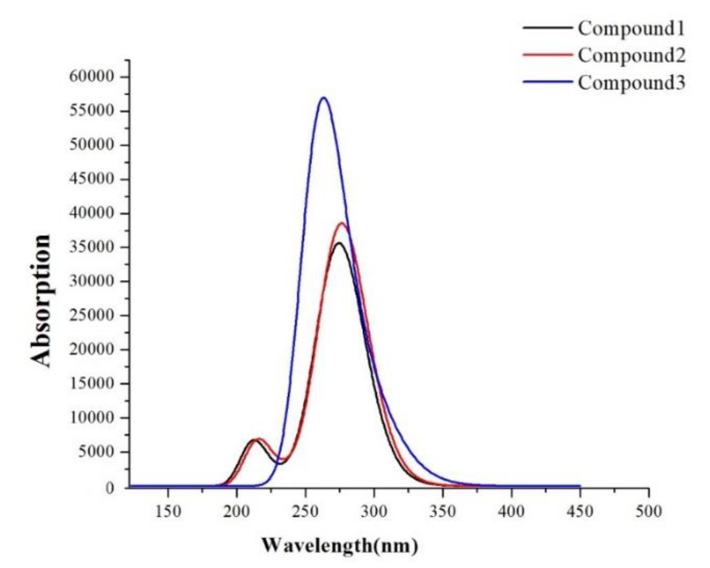
3.2. UV–Vis Absorption and Electrochemical Property

As an essential characteristic of the synthesized molecules as HTMs, the UV–vis absorption profile of Compounds 1–3 were measured in DCM, as shown in Figure 1 and Table S1. It is clear from Figure 1 that all compounds are absorbing at wavelengths below 300 nm or less (due to π–π* transition) except for Compound 3 that shows ICT (intramolecular charge transfer) broadband at 292 nm owing to the thiazolyl moiety [43], which is overlapped with n–π* band nearby 395 nm. The major absorption peaks for these compounds are thus away enough from the maximum absorption wavelength of perovskite photosensitizer CH3NH3PbI3−xClx (360 nm) [44], indicating that these compounds are transparent and potentially suitable as HTMs. The optical band gap energy (Eg) for these compounds were obtained from the onset absorption as shown in Table 1.
The HOMO energies for the synthesized compounds were measured by cyclic voltammetry from which the onset oxidation peaks shown in the voltammograms (Figure 2, Figure 3 and Figure 4) were used to calculate the HOMO energies. The LUMO energies were then obtained by the summation of Eg with the HOMO energy as shown in Table 1.

3.3. Computational Investigation

3.3.1. Ground-State Geometries and Frontier Molecular Orbitals

As an approximation for easy calculation, it is generally accepted for an organic molecule that replacement of a long chain (in our case -C12H25 and -C10H21) with short ones such as -C2H5 and -CH3, respectively, during the structural optimization will have a marginal effect on the electronic properties [47]. Thus, DFT/B3LYP/6-31G(d) has been used to optimize the three compounds after being simplified with short chains. The optimized structures and parameters were shown in Supplementary Materials: Figure S1 and Table S2. The bond lengths between nitrogen atoms and benzene rings of compounds have a slight difference. Moreover, Compounds 1 and 2 have slightly different dihedral angles, which indicates that the length of hydrocarbon chains had little influence on the planarity. However, it had obviously changed the planarity when phenothiazine was introduced to diphenylamine moiety through thiazole ring. The HOMO and LUMO indicate the distribution of the electronic density, respectively, which contributed to electron transition. It is shown in Figure 5 that the electronic density of the HOMO of both Compounds 1 and 2 are mainly distributed over the whole molecule except the side alkyl groups. The LUMO’s electronic density of Compounds 1 and 2 are mainly distributed over diphenylamine moiety and phenylamine moiety, respectively. In Compound 3, however, the electronic density distribution in the HOMO level is mainly distributed on the thiazolylphenothiazine moiety with a little distribution on diarylamine moiety. The energy of LUMO of Compound 3 shows that the electronic density distribution has moved toward the center of the molecule.
The frontier molecular orbitals energy levels (HOMO and LUMO) were calculated and the results are listed in Table 2 and Figure 6. As shown in Table 2, the HOMO energy levels were in the increasing order Compound 3 < Compound 1 < Compound 2. The energy gap of HTMs as estimated by ∆H−L = ELUMO − EHOMO reflects that Compound 3 revealed the lowest bandgap among the three molecules. These results indicate that Compound 3 is the most energy-stabilized molecule compared to Compounds 1 and 2, owing to its lower HOMO and bandgap energies, in a good correlation with the extended conjugation caused by the thiazole ring that acts as an internal auxiliary acceptor [43]. The energy levels of HTMs and perovskite (CH3NH3PbI3), and the reference Spiro-OMeTAD, are shown in Figure 6. As shown in Figure 6, the experimental and computational values of the HOMO energies were in good agreement. The HOMO energy levels for Compounds 1–3 were higher than the valence band (VB) of the perovskite film, thus indicating their suitability for hole injection. At the same time, their LUMO energy levels were all higher than that of the conduction band of perovskite film that benefits the inhabitation of the electron back in the perovskite system.

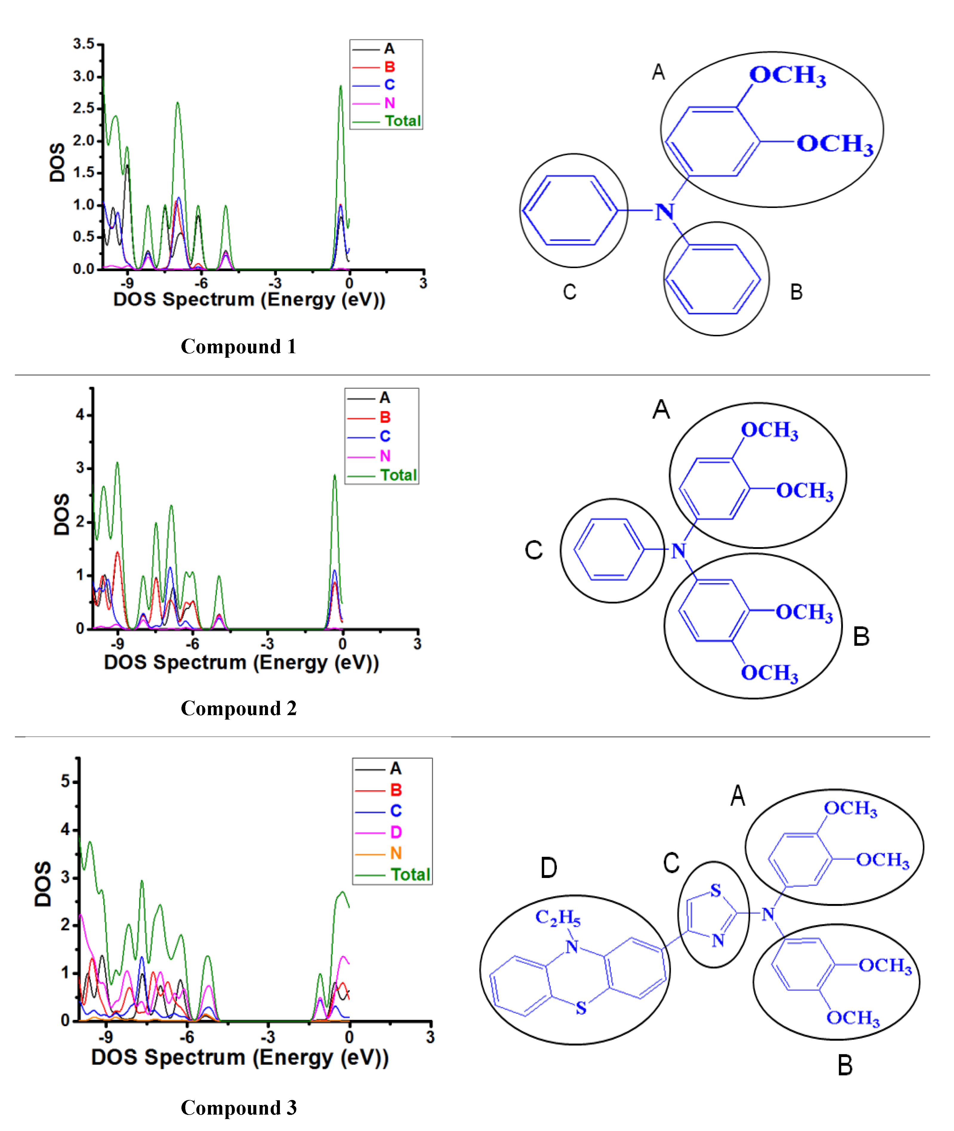
3.3.2. Density of States (DOS) and Frontier Molecular Orbitals

In order to get a clear view of the roles of each part among the compounds. The DOS and partial density of states (PDOS) were plotted under the GaussSum software. Additionally, the DFT with B3LYP functional at the 6–31G(d) basis set was used to calculate the DOS and PDOS of Compounds 1–3. The PDOS are shown in Figure 7, and the contribution of every unit for DOS are listed in Table S3. As shown in Figure 7, when the B part (phenyl) of Compound 1 is replaced by dimethoxyphenyl to produce Compound 2, the contribution of the B part of the molecule to HOMO orbital was slightly increased. When we replaced the C part (phenyl) with the thiazole-based on Compound 2 and introduced the D part (10-ethyl-10H-phenothiazine) at the end of the C part, the contribution of the C part to the HOMO orbital remained unchanged; the contribution of the A part, B part and N to the HOMO orbital was greatly reduced, and the newly introduced D part provides great contribution for the HOMO orbital. The HOMO level of the molecule was also decreased, which is favorable for hole injection. Since the LUMO of Compounds 1–3 were all much higher than the conduction band (CB) of perovskite film, we did not analyze the LUMO orbitals of Compounds 1–3 in detail here. To sum up, the introduction of dimethoxyphenyl will increase the HOMO energy levels of the molecules, which will have a very adverse effect on the hole injection. However, the introduction of 10-ethyl-10H-phenothiazine will further reduce the HOMO energy levels of the molecules, which will have a very favorable impact on the hole injection.

3.3.3. Ionization Potentials (IP), Electron Affinities (EA) and Absolute Hardness

As shown in Table 3, the IP and EA values indicate that Compound 2 had both the lowest ionization potential and electron affinity, indicating its suitability as the best hole transfer molecule among the studied compounds. It has been reported that the value of chemical hardness has an impact on the intramolecular charge transfer in such a way that a higher hardness value would help to resist the intramolecular charge transfer and the absolute hardness η means the ability of energy to resist electron changes [47,48]. Among three molecules, Compound 2 has both the lowest IP, EA and relatively higher value of η, and thus the overall results suggest Compound 2 to be the suitable HTM.

3.3.4. Absorption Spectra

The absorption spectra are shown in Figure 8, and transition information are listed in Table 4. Thereinto, the absorption wavelength is an important parameter to describe optical response. As shown in Table 4, the values of S1 states of them were calculated to be 277.67 nm (for Compound 1), 278.14 nm (for Compound 2) and 302.71 nm (for Compound 3), respectively. From the simulated spectra, it can be found that Compound 2 made a little red-shifted spectrum compared to Compound 1, and Compound 3 made a blue-shifted spectrum about 10 nm. We can see further from Table 4, the order of the absorption peak was Compound 2 > Compound 1 > Compound 3, and the absorption peaks of Compounds 1–3 were all in the range of 250–350 nm (Figure 1 and Table S1 in Supplementary Materials). It further proves the accuracy of the calculated data on absorption spectra. Absorption spectra for the three compounds reside in the non-visible region, which benefits optical transparency.

3.3.5. Fluorescence Lifetime

The fluorescence lifetime τ1 and excited-state lifetime τ2 of the molecules both reflect the time that the exciton stays in the excited state. Previous reports on carbazole substituted NP based derivative as HTM showed that the short excitation lifetime could depress unfavorable relaxation of the excited state [36]. The fluorescence energy and fluorescence lifetime τ1 are shown in Table 5, and the vertical excitation energy and excited-state lifetime τ2 and the hardness ƞ are shown in Table S4. From the point of view of the lifetime, it can be found that Compound 3 had the significantly longer τ1 and τ2 rather than other compounds, which could increase its relaxation and this process is disadvantageous for the excited molecules to the ground state. However, the fact that Compounds 1 and 2 had higher hardness ƞ and a smaller lifetime could promote the two compounds to have good HTM performance in comparison with Compound 3.

3.3.6. Charge Transport and Hole Mobility

Hole transport is a critical parameter for estimation of HTMs performance and well performance of HTMs will promote the improvement of short-circuit currents. Table 6 and Table 7 show the calculated hole reorganization energies and hole mobilities, which show the order of the hole mobilities as Compound 2 > Compound 3 > Compound 1. We can also see from Table 6 that Compound 3 had lower hole reorganization energy, which was conducive to the improvement of hole mobilities; but Compound 3 had small hole transfer integrals, which was very unfavorable for further development of hole mobility. It is hoped that the addition of -OCH3 can improve the hole transfer integrals and can further improve the hole transport in the design of the triphenylamine system.

4. Conclusions

Three novel triarylamine Compounds 1–3 were designed and synthesized for perovskite solar cells. Optical absorption and computational investigation indicated the suitability of these compounds as HTMs as they are transparent in the absorption region of the perovskite photosensitizer. The experimental and computational values of HOMO energies were in good agreement and the values were suited well with the perovskite photosensitizer. Additionally, the computed hole transfer mobility was the best for Compound 2 among the three compounds. Future studies will focus on the film forming ability of these compounds and their use for device fabrication and application as HTMs for the perovskite solar cell and the outcome will be reported in a future article.

Supplementary Materials

The following are available online at https://0-www-mdpi-com.brum.beds.ac.uk/article/10.3390/ma14113128/s1, the supplementary file (Figures S1–S33 and Tables S1–S4) contains the NMR, ATR-FTIR, HRMS charts and others for the synthesized compounds.

Author Contributions

L.M.N. Synthesis, methodology and writing the draft, R.M.E.-S. conceptualization, writing the manuscript and supervision, Q.L. and Y.L. computation and A.M.A. supervision and revision. All authors have read and agreed to the published version of the manuscript.

Funding

This work was supported by the King Abdulaziz City for Science and Technology (KACST), Saudi Arabia, under grant No. (1-18-01-009-0041).

Institutional Review Board Statement

Not applicable.

Informed Consent Statement

Not applicable.

Data Availability Statement

The data presented in this study are available in Supplementary Materials here.

Acknowledgments

The authors wish to express their gratitude to the King Abdulaziz City for Science and Technology (KACST), Saudi Arabia, for funding the student Laila M. Nhari a grant number 1-18-01-009-0041. Additionally, the authors are thankful to the Deanship of Scientific Research (DSR), King Abdulaziz University for their technical support.

Conflicts of Interest

The authors declare no conflict of interest.

References

  1. Nhari, L.M.; El-Shishtawy, R.M.; Asiri, A.M. Recent Progress in Organic Hole Transport Materials for Energy Applications. Dye. Pigment. 2021, 109465. [Google Scholar] [CrossRef]
  2. Dhingra, P.; Singh, P.; Rana, P.J.S.; Garg, A.; Kar, P. Hole-Transporting Materials for Perovskite-Sensitized Solar Cells. Energy Technol. 2016, 4, 891–938. [Google Scholar] [CrossRef]
  3. Shirota, Y. Organic materials for electronic and optoelectronic devices. J. Mater. Chem. 2000, 10, 1–25. [Google Scholar] [CrossRef]
  4. Nishimura, H.; Okada, I.; Tanabe, T.; Nakamura, T.; Murdey, R.; Wakamiya, A. Additive-free, Cost-Effective Hole-Transporting Materials for Perovskite Solar Cells Based on Vinyl Triarylamines. ACS Appl. Mater. Interfaces 2020, 12, 32994–33003. [Google Scholar] [CrossRef] [PubMed]
  5. Yu, Z.; Sun, L. Recent Progress on Hole-Transporting Materials for Emerging Organometal Halide Perovskite Solar Cells. Adv. Energy Mater. 2015, 5, 1500213. [Google Scholar] [CrossRef]
  6. Sheibani, E.; Yang, L.; Zhang, J. Recent Advances in Organic Hole Transporting Materials for Perovskite Solar Cells. Sol. RRL 2020, 4, 2000461. [Google Scholar] [CrossRef]
  7. Shariatinia, Z. Recent progress in development of diverse kinds of hole transport materials for the perovskite solar cells: A review. Renew. Sustain. Energy Rev. 2020, 119, 109608. [Google Scholar] [CrossRef]
  8. Suranagi, S.R.; Singh, R.; Kim, M. Enhancing the power conversion of the perovskite solar cells via structural tuning of BTT(DPP)3-based low bandgap hole transporting material. Dye. Pigment. 2019, 163, 525–532. [Google Scholar] [CrossRef]
  9. Gao, W.-J.; Yu, H.-J.; Chen, J.; Xiao, J.; Fang, J.-K.; Jia, X.-R.; Peng, C.-F.; Shao, G.; Kuang, D.-B. Simple hole-transporting materials containing twin-carbazole moiety and unconjugated flexible linker for efficient and stable perovskite solar cells. Chem. Eng. J. 2021, 405, 126434. [Google Scholar] [CrossRef]
  10. Guo, J.; Zhang, Y.; Cai, W.; Zhang, Z.; He, R.; Shen, W.; Li, M. Effect of double bond conjugation on hole mobility of thio-phene-based hole transport materials in perovskite solar cells. Mater. Chem. Phys. 2020, 240, 122058. [Google Scholar] [CrossRef]
  11. Li, M.; Ma, S.; Mateen, M.; Liu, X.; Ding, Y.; Gao, J.; Yang, Y.; Zhang, X.; Wu, Y.; Dai, S. Facile donor (D)-π-D triphenyla-mine-based hole transporting materials with different π-linker for perovskite solar cells. Sol. Energy 2020, 195, 618–625. [Google Scholar] [CrossRef]
  12. Azmi, R.; Nam, S.Y.; Sinaga, S.; Akbar, Z.A.; Lee, C.-L.; Yoon, S.C.; Jung, I.H.; Jang, S.-Y. High-performance dopant-free conjugated small molecule-based hole-transport materials for perovskite solar cells. Nano Energy 2018, 44, 191–198. [Google Scholar] [CrossRef]
  13. Li, M.; Wu, J.; Wang, G.; Wu, B.; Sun, Z.; Xue, S.; Qiao, Q.; Liang, M. The donor-dependent methoxy effects on the perfor-mance of hole-transporting materials for perovskite solar cells. J. Energy Chem. 2020, 47, 10–17. [Google Scholar] [CrossRef]
  14. Ashassi-Sorkhabi, H.; Salehi-Abar, P. Evaluation of the performance of stilbene-based hole transport materials with an em-phasis on their configuration for use in perovskite solar cells. Sol. Energy 2019, 188, 951–957. [Google Scholar] [CrossRef]
  15. Ashassi-Sorkhabi, H.; Salehi-Abar, P.; Asghari, E.; Kazempour, A. Structural effect on the thermodynamic and electrochem-ical properties of pyrene-based hole transport materials. J. Mol. Liq. 2019, 285, 338–346. [Google Scholar] [CrossRef]
  16. Dong, Y.; Zhu, H.; Cao, X.; Han, Y.-P.; Zhang, H.-Y.; Yang, Q.; Zhang, Y.; Zhao, J.; Yin, G.; Wang, S. Simple 9,10-dihydrophenanthrene based hole-transporting materials for efficient perovskite solar cells. Chem. Eng. J. 2020, 402, 126298. [Google Scholar] [CrossRef]
  17. Ashassi-Sorkhabi, H.; Salehi-Abar, P. Design of two novel hole transport materials via replacing the core of spiro-OMeTAD with tetrathiafulvalene and tetraazafulvalene for application in perovskite solar cells. Sol. Energy 2018, 173, 132–138. [Google Scholar] [CrossRef]
  18. Kula, S.; Pająk, A.; Szlapa-Kula, A.; Mieszczanin, A.; Gnida, P.; Lipiński, M.; Schab-Balcerzak, E. 9,9′-Bifluorenylidene de-rivatives as novel hole-transporting materials for potential photovoltaic applications. Dye. Pigment. 2020, 174, 108031. [Google Scholar] [CrossRef]
  19. Dalkılıç, Z.; Lee, C.B.; Choi, H.; Nar, I.; Yavuz, N.K.; Burat, A.K. Tetra and octa substituted Zn(II) and Cu(II) phthalocyanines: Synthesis, characterization and investigation as hole-transporting materials for inverted type-perovskite solar cells. J. Organomet. Chem. 2020, 922, 121419. [Google Scholar] [CrossRef]
  20. Guo, J.; Sun, M.; Meng, X.; Zhu, H.; Ma, C.; Hu, S.; Shen, J.; Wang, Q.; Gao, J. Impact of peripheral groups on novel asym-metric phthalocyanine-based hole-transporting materials for perovskite solar cells. Dye. Pigment. 2020, 177, 108301. [Google Scholar] [CrossRef]
  21. Yin, X.; Wang, C.; Zhao, D.; Shrestha, N.; Grice, C.R.; Guan, L.; Song, Z.; Chen, C.; Li, C.; Chi, G.; et al. Binary hole transport materials blending to linearly tune HOMO level for high efficiency and stable perovskite solar cells. Nano Energy 2018, 51, 680–687. [Google Scholar] [CrossRef]
  22. Luo, D.; Jin, R. Theoretical characterisation and design of D–π–A star-shaped molecules with triphenylamine as core and diketopyrrolopyrroles as arms for organic solar cells. Mol. Phys. 2018, 117, 1825–1832. [Google Scholar] [CrossRef]
  23. Wang, Q.; Zeng, Z.; Li, Y.; Chen, X. Efficient strategies for improving the performance of EDOT derivatives and TPA deriva-tives-based hole transport materials for perovskite solar cells. Sol. Energy 2020, 208, 10–19. [Google Scholar] [CrossRef]
  24. Qiu, M.; Pei, W.; Lu, Q.; Li, Z.; Li, Y.; Liang, J. DFT Characteristics of Charge Transport in DBTP-Based Hole Transport Ma-terials. Appl. Sci. 2019, 9, 2244. [Google Scholar] [CrossRef] [Green Version]
  25. Wazzan, N.; El-Shishtawy, R.M.; Irfan, A. DFT and TD–DFT calculations of the electronic structures and photophysical properties of newly designed pyrene-core arylamine derivatives as hole-transporting materials for perovskite solar cells. Theor. Chem. Acc. 2017, 137, 9. [Google Scholar] [CrossRef]
  26. El-Shishtawy, R.M. Functional dyes, and some hi-tech applications. Int. J. Photoenergy 2009, 2009, 434897. [Google Scholar] [CrossRef]
  27. Calió, L.; Kazim, S.; Grätzel, M.; Ahmad, S. Hole-transport materials for perovskite solar cells. Angew. Chem. Int. Ed. 2016, 55, 14522–14545. [Google Scholar] [CrossRef]
  28. Frisch, M.J.; Trucks, G.W.; Schlegel, H.B.; Scuseria, G.E.; Robb, M.A.; Cheeseman, J.R.; Scalmani, G.; Barone, V.; Men-nucci, B.; Petersson, G.A.; et al. Gaussian 09, Revision A.01; Gaussian, Inc.: Wallingford, CT, USA, 2009. [Google Scholar]
  29. Hohenberg, P.; Kohn, W. Inhomogeneous electron gas. Phys. Rev. 1964, 136, 864–871. [Google Scholar] [CrossRef] [Green Version]
  30. Becke, A.D. Density-functional exchange-energy approximation with correct asymptotic behavior. Phys. Rev. A 1988, 38, 3098–3100. [Google Scholar] [CrossRef]
  31. Huang, S.; Zai, J.; Ma, D.; Hu, Z.; He, Q.; Wu, M.; Chen, D.; Chen, Z.; Qian, X. Improving the catalytic performance of Ni 3 S 4 -PtCo heteronanorods via Mott-Schottky effect toward the reduction of iodine couples in dye-sensitized solar cells. Electrochim. Acta 2017, 241, 89–97. [Google Scholar] [CrossRef]
  32. Adamo, C.; Jacquemin, D. The calculations of excited-state properties with Time-Dependent Density Functional Theory. Chem. Soc. Rev. 2013, 42, 845–856. [Google Scholar] [CrossRef]
  33. Yanai, T.; Tew, D.; Handy, N.C. A new hybrid exchange–correlation functional using the Coulomb-attenuating method (CAM-B3LYP). Chem. Phys. Lett. 2004, 393, 51–57. [Google Scholar] [CrossRef] [Green Version]
  34. O’Boyle, N.M.; Tenderholt, A.L.; Langner, K.M. cclib: A library for package-independent computational chemistry algorithms. J. Comput. Chem. 2008, 29, 839–845. [Google Scholar] [CrossRef]
  35. Chattaraj, P.K.; Sarkar, U.; Roy, D.R. Electrophilicity index. Chem. Rev. 2006, 107, 2065–2091. [Google Scholar] [CrossRef]
  36. Zhang, Y.; Wang, L.; Mao, L.; Zhang, J. Carbazole-substituted NP-based derivative as hole transporting material for highly efficient perovskite solar cells. Spectrochim. Acta Part A Mol. Biomol. Spectrosc. 2020, 228, 117808. [Google Scholar] [CrossRef]
  37. Ren, P.; Sun, C.; Shi, Y.; Song, P.; Yang, Y.; Li, Y. Global performance evaluation of solar cells using two models: From charge-transfer and recombination mechanisms to photoelectric properties. J. Mater. Chem. C 2019, 7, 1934–1947. [Google Scholar] [CrossRef]
  38. Köse, M.E.; Mitchell, W.J.; Kopidakis, N.; Chang, C.H.; Shaheen, S.E.; Kim, K.; Rumbles, G. Theoretical studies on conju-gated phenyl-cored thiophene dendrimers for photovoltaic applications. J. Am. Chem. Soc. 2007, 129, 14257–14270. [Google Scholar] [CrossRef]
  39. Zou, L.Y.; Ren, A.M.; Feng, J.K.; Liu, Y.L.; Ran, X.Q.; Sun, C.C. Theoretical study on photophysical properties of multi-functional electroluminescent molecules with different π-conjugated bridges. J. Phys. Chem. A 2008, 112, 12172–12178. [Google Scholar] [CrossRef]
  40. Valeev, E.F.; Coropceanu, V.; Filho, D.A.D.S.; Salman, A.S.; Brédas, J.-L. Effect of Electronic Polarization on Charge-Transport Parameters in Molecular Organic Semiconductors. J. Am. Chem. Soc. 2006, 128, 9882–9886. [Google Scholar] [CrossRef]
  41. Marcus, R.A. Chemical and Electrochemical Electron-Transfer Theory. Annu. Rev. Phys. Chem. 1964, 15, 155–196. [Google Scholar] [CrossRef]
  42. Bisquert, J. Interpretation of electron diffusion coefficient in organic and inorganic semiconductors with broad distributions of states. Phys. Chem. Chem. Phys. 2008, 10, 3175–3194. [Google Scholar] [CrossRef]
  43. El-Shishtawy, R.; Borbone, F.; Al-Amshany, Z.M.; Tuzi, A.; Barsella, A.; Asiri, A.M.; Roviello, A. Thiazole azo dyes with lateral donor branch: Synthesis, structure and second order NLO properties. Dye. Pigment. 2013, 96, 45–51. [Google Scholar] [CrossRef]
  44. Hsieh, C.-M.; Yu, Y.-L.; Chen, C.-P.; Chuang, S.-C. Effects of the additives n-propylammonium or n-butylammonium iodide on the performance of perovskite solar cells. RSC Adv. 2017, 7, 55986–55992. [Google Scholar] [CrossRef]
  45. El-Shishtawy, R.M.; Decoppet, J.-D.; Al-Zahrani, F.A.; Cao, Y.; Khan, S.B.; Al-Ghamdi, M.S.; Alhogbi, B.G.; Asiri, A.M.; Zakeeruddin, S.M.; Grätzel, M. Influence of redox electrolyte on the device performance of phenothiazine based dye sensi-tized solar cells. New J. Chem. 2018, 42, 9045–9050. [Google Scholar] [CrossRef]
  46. Xiao, Y.; Han, G.; Chang, Y.; Zhou, H.; Li, M.; Li, Y. An all-solid-state perovskite-sensitized solar cell based on the dual func-tion polyaniline as the sensitizer and p-type hole-transporting material. J. Power Sources 2014, 267, 1–8. [Google Scholar] [CrossRef]
  47. Oliveira, E.F.; Lavarda, F.C. [Unesp] Effect of the length of alkyl side chains in the electronic structure of conjugated polymers. Mater. Res. 2014, 17, 1369–1374. [Google Scholar] [CrossRef] [Green Version]
  48. Jin, R.; Wang, K. Rational Design of Diketopyrrolopyrrole-Based Small Moleculesas Donating Materials for Organic Solar Cells. Int. J. Mol. Sci. 2015, 16, 20326–20343. [Google Scholar] [CrossRef] [Green Version]
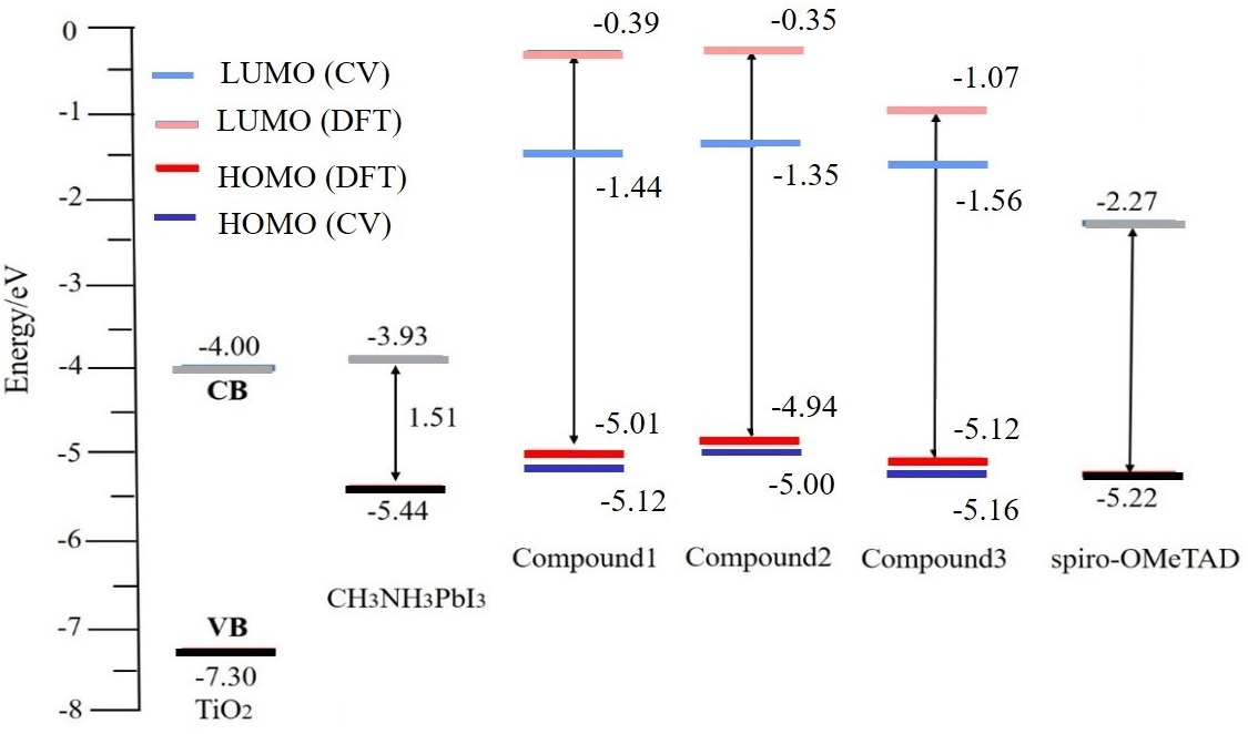
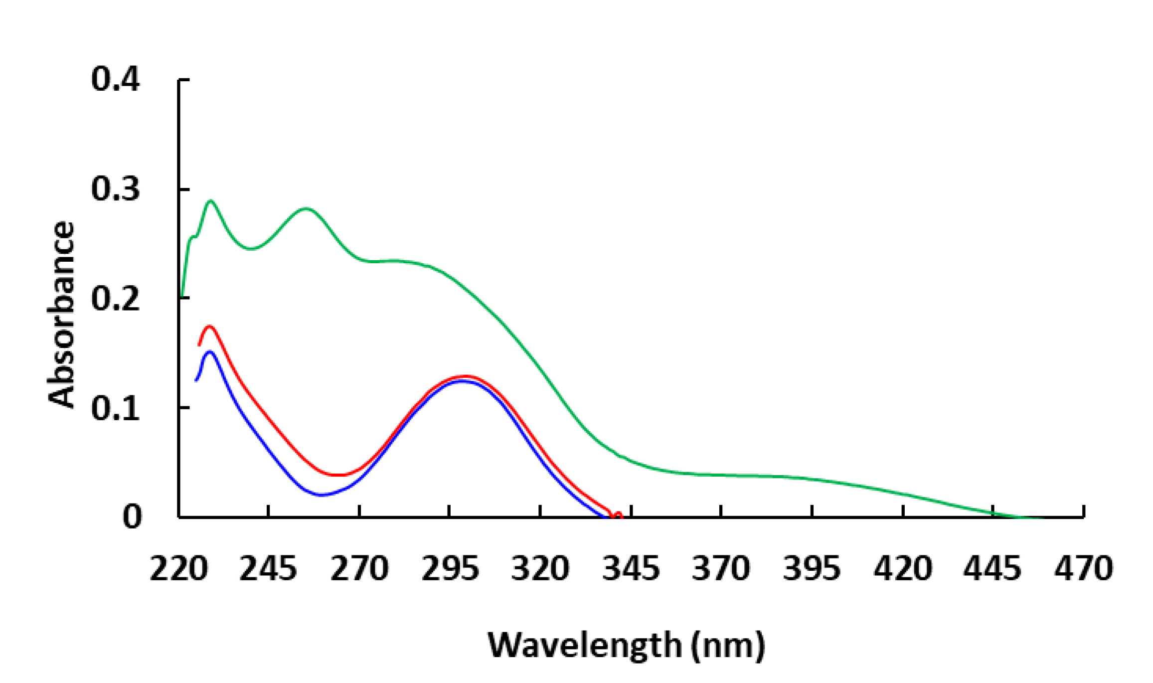
Scheme 1. Synthesis of Compounds 1–3.
Materials 14 03128 sch001
Figure 1. The experimental UV–Vis absorption spectra of the compounds in DCM solutions (10−5 mol/L).
Materials 14 03128 g001
Figure 2. Cyclic voltammogram of Compound 1 in DCM solution (10−3 M).
Materials 14 03128 g002
Figure 3. Cyclic voltammogram of Compound 2 in DCM solution (10−3 M).
Materials 14 03128 g003
Figure 4. Cyclic voltammogram of Compound 3 in DCM solution (10−3 M).
Materials 14 03128 g004
Figure 5. The molecular orbitals HOMO and LUMO of the three original molecules.
Materials 14 03128 g005
Figure 6. Energy level diagram of the investigated hole transporting materials.
Materials 14 03128 g006
Figure 7. Partial density of states graphs of three compounds.
Materials 14 03128 g007
Figure 8. The computed UV–Vis absorption spectra of the compounds.
Materials 14 03128 g008
Table 1. Summary of energy levels and Eg of Compounds 13.
MoleculeΛ a
(nm)
Egb
(eV)
Eoxc
(V)
Eox (Ferrocene) c
(V)
HOMO d
(eV)
LUMO e
(eV)
Compound 13373.680.720.40−5.12−1.44
Compound 23403.650.600.40−5.00−1.35
Compound 34452.790.760.40−5.16−2.37
a λonest Measured by UV–Vis absorption spectra (Figure 1); b The optical band gap was estimated from the onset wavelength of absorption using the equation Eg = 1240/λonset; c oxidation potentials measured by cyclic voltammetry (Figure 2, Figure 3 and Figure 4); d HOMO = −(Eox + 4.80 − Eox (Ferrocene)) eV [45,46]; e The LUMO energy level was calculated using the equation ELUMO = EHOMO + Eg.
Table 2. Calculated energy levels of frontier molecular orbital (HOMO and LUMO), and the energy gaps ΔL-H of the three studied molecules.
MoleculesHOMO (eV)LUMO (eV)ΔL-H (eV)
Compound 1−5.007438148−0.3877621654.619675983
Compound 2−4.938049129−0.3532037124.584845416
Compound 3−5.125263423−1.0710399174.054223506
Table 3. The ionization potential IP (eV), electron affinities EA (eV) and absolute hardness η (eV).
MoleculesCompound 1Compound 2Compound 3
IP4.8264960764.7591315844.920280097
EA0.5248095590.5159985141.29218136
η2.1508432592.1215665351.814049369
Table 4. The vertical excitation energy (eV), absorption peak (nm), configuration interaction (CI) coefficient and oscillator strengths (f) of investigated molecules.
MoleculesStateEnergyλfCI
Compound 1S14.4652277.670.2767H-L/0.66564
S24.5111274.840.3910H-L + 1/0.66581
S34.5623271.760.2050H-L + 2/0.65691
S44.9924248.340.0315H-L + 4/0.48494
S55.0173247.110.0321H-L + 3/0.53146
S65.8306212.640.1661H-L + 2/0.38636
Compound 2S14.4577278.140.3412H-L/0.64282
S24.4771276.930.4976H-L + 1/0.65286
S34.5514272.410.1049H-L + 2/0.65475
S44.9754249.190.0358H-L + 3/0.44687
S54.9942248.260.0271H-L + 4/0.42356
S65.7443215.840.1691H − 1-L + 2/0.50837
Compound 3S14.0959302.710.1619H-L/0.57662
S24.3452285.330.1596H − 1-L/0.48943
S34.5086274.990.0480H-L + 3/0.39172
S44.6656265.740.1675H-L + 1/0.43774
S54.7392261.610.8023H − 1-L + 2/0.36926
S64.7891258.890.3343H-L + 5/0.42187
Table 5. The fluorescence energy (eV), fluorescence emission peak (nm), oscillator strengths (f), electron transitions and fluorescence lifetime τ1 (ns) of investigated molecules.
MoleculesStateEnergyλfCIτ1
Compound 1S13.8032326.000.2075H-L/0.690267.6785
Compound 2S13.8016326.140.2227H-L/0.688227.1604
Compound 3S12.9393421.820.0355H-L/0.6419175.141
Table 6. The hole reorganization energies λh (eV) and electron reorganization energies λe (eV) of three investigated molecules.
MoleculesCompound 1Compound 2Compound 3
λh0.4834890790.4954566440.435409291
λe0.3196820130.3757184080.531043686
Table 7. The transfer integrals V (eV), r (Å) is centroid to centroid distance, hopping rates k (s−1) and mobilities µ (cm2 V−1s−1) of molecules.
MoleculesCompound 1Compound 2Compound 3
r5.368464.879624.90008
Vh0.002176910.068028450.024898413
Ve0.0014966260.0302046320.02938829
kh (×1011) 0.01063869.141432.33463
ke (×1011) 0.03014566.587641.16805
µh0.0000593010.0420980.010842
µe0.000168030.0303370.0054243
Publisher’s Note: MDPI stays neutral with regard to jurisdictional claims in published maps and institutional affiliations.

