
Modeling and Analysis of a SiC Microstructure-Based Capacitive Micro-Accelerometer


1
School of Instrumentation and Optoelectronic Engineering, Beihang University, Beijing 100191, China
2
School of Energy and Power Engineering, Beihang University, Beijing 100191, China
*
Authors to whom correspondence should be addressed.
Materials 2021, 14(20), 6222; https://0-doi-org.brum.beds.ac.uk/10.3390/ma14206222
Submission received: 27 August 2021
/
Revised: 11 October 2021
/
Accepted: 14 October 2021
/
Published: 19 October 2021
Abstract
:In this study, a comb-type capacitive accelerometer based on a silicon carbide (SiC) microstructure is presented and investigated by the finite element method (FEM). It has the advantages of low weight, small volume, and low cross-coupling. Compared with silicon(111) accelerometers with the same structure, it has a higher natural frequency. When the accelerometer vibrates, its resistive force consists of two main components: a viscous damping and an elastic damping force. It was found that viscous damping dominates at low frequency, and elastic damping dominates at high frequency. The second-order linear system of the accelerometer was analyzed in the time-frequency domain, and its dynamic characteristics were best when the gap between the capacitive plates was 1.23 μm. The range of this accelerometer was 0–100 g, which is 1.64 times that of a silicon(111) accelerometer with the same structure. In addition, the accelerometer could work normally at temperatures of up to 1200 °C, which is much higher than the working temperatures of silicon devices. Therefore, the proposed accelerometer showed superior performance compared to conventional silicon-based sensors for inertial measurements.
1. Introduction
In the early 1940s, German researchers developed the world’s first pendulous gyroscope accelerometer [1]. It was applied in the V-2 rocket, which greatly improved the rocket’s hit rate [2]. For more than half a century thereafter, due to the demand for inertial measurement units (IMUs) in aviation, navigation, and aerospace, various types of accelerometers emerged, and their performance and accuracies have been greatly improved [3,4].
In the 1980s, micro-accelerometers were made using integrated circuits (ICs) and micromachining, which gave them the advantages of small volume [5], light weight [6], low power consumption [7], low cost [8], easy integration [9], strong overload capacity [10], and mass production [11]. These not only became the core components of micro-inertial measurement units (MIMUs) [12] but also rapidly expanded into other civil fields [13,14]. In 1979, Roylance and Angell from Stanford University produced the first open-loop silicon accelerometer using silicon ICs [15] and released the product in the early 1980s. In the late 1980s, people began to study various closed-loop force-balanced silicon micro-accelerometers and made great progress. In 1989, Analog Devices Inc. (ADI) began research into silicon comb-type capacitive micro-accelerometers [16], and cooperated with the Siemens company to develop its electronic measurement circuit in 1990. In 1992, the accelerometer developed by ADI met the performance index requirements for automobile safety airbags. It was put into production in 1993, and a series of products followed: ADXL50 [17], ADXL05 [18], and others [19,20].
In 1995, the electronic circuit of the accelerometer, developed by the LITEF company in Germany, adopted the scheme of pulse-width modulation, digital output, and closed-loop control. The range of the accelerometer was ±10 g; the scale factor stability was 300 ppm, and the bias stability was 250 μg. This kind of micro-accelerometer was combined with a fiber optic gyroscope (FOG) to form the MIMU for vehicle navigation [21]. The Applied MEMS company in the United States developed a very low-noise application specific integrated circuit (ASIC) micromachined accelerometer for seismic exploration in 2002. This single-axis accelerometer used the ASIC for the force feedback system, and it consisted of two parts: a capacitance detector and a closed-loop force feedback circuit. The noise could be kept below −150 dB g/Hz1/2 in the frequency range of 3–200 Hz.
According to the detection principle, micro-accelerometers can be divided into piezoresistive [22], piezoelectric [23], resonant [24], capacitive [25], and other forms. Among them, capacitive accelerometers have the advantages of high accuracy [26], low-noise [27], low temperature sensitivity [28], low power consumption [29], and a simple structure [30]. Therefore, they gradually became mainstream in the development of micro-silicon acceleration sensors.
Over the past few decades, silicon devices have significantly improved. However, they are approaching the performance limits defined by the basic material properties of silicon [31], and further performance improvements can only be achieved by migrating to more powerful semiconductor materials [32]. As a representative of the third generation, silicon carbide has excellent physical, chemical, and electrical properties, such as a wide band-gap [33], high mechanical strength [34], high thermal conductivity [35], high melting point [36], and corrosion resistance [37]. Compared with the Si devices, SiC MEMS devices can work at higher temperatures and in harsher environments [38]. The wide band-gap and high thermal stability of SiC allow certain types of devices to operate indefinitely at junction temperatures of 300 °C or higher without measurable performance degradation. The potential markets for SiC sensors include the Radio Frequency (RF) MEMS [39], the pressure sensors used in the petroleum industry [40], the acceleration sensors in aircraft engines and motors [41], and the optical MEMS [42].
In this paper, we propose a differential capacitive accelerometer based on a SiC microstructure by FEM. Firstly, the working principle and the process flow of the accelerometer was introduced. Then the structural parameters of the accelerometer were optimized to avoid cross-coupling. In the modal analysis, we found that a SiC-based accelerometer had a higher natural frequency compared to a Si-based accelerometer with the same structure. Secondly, a good damping design can improve the dynamic characteristics [43]. Therefore, the squeeze film air damping of the accelerometer was studied, and we found that, when the vibration frequency was low, the viscous damping force of the air film increased linearly with an increase in the vibration frequency, and the elastic damping force increased slowly. However, when the vibration frequency was high, the viscous damping force of the air film decreased with an increase in vibration frequency, and the elastic damping force increased rapidly. Moreover, the accelerometer’s second-order linear system was analyzed in the frequency and time domains. The analysis showed that the dynamic characteristics were at their best when the gap between the capacitive plates was 1.23 μm. That is, the accelerometer has a large bandwidth and no resonant peak in its amplitude-frequency curve, and a fast output in its step response. Lastly, the performance characteristics of the SiC-based accelerometer showed a range of 0–100 g, which is 1.64 times of that of a silicon(111) accelerometer of the same structure. In addition, the SiC-based accelerometer worked normally at high temperatures up to 1200 °C, which is much higher than the working temperature (250 °C) of the silicon devices. In summary, the proposed accelerometer showed great potential as an alternative to conventional Si sensors in inertial measurement applications.
2. Working Principles
2.1. Design of a Comb-Type Capacitive Accelerometer
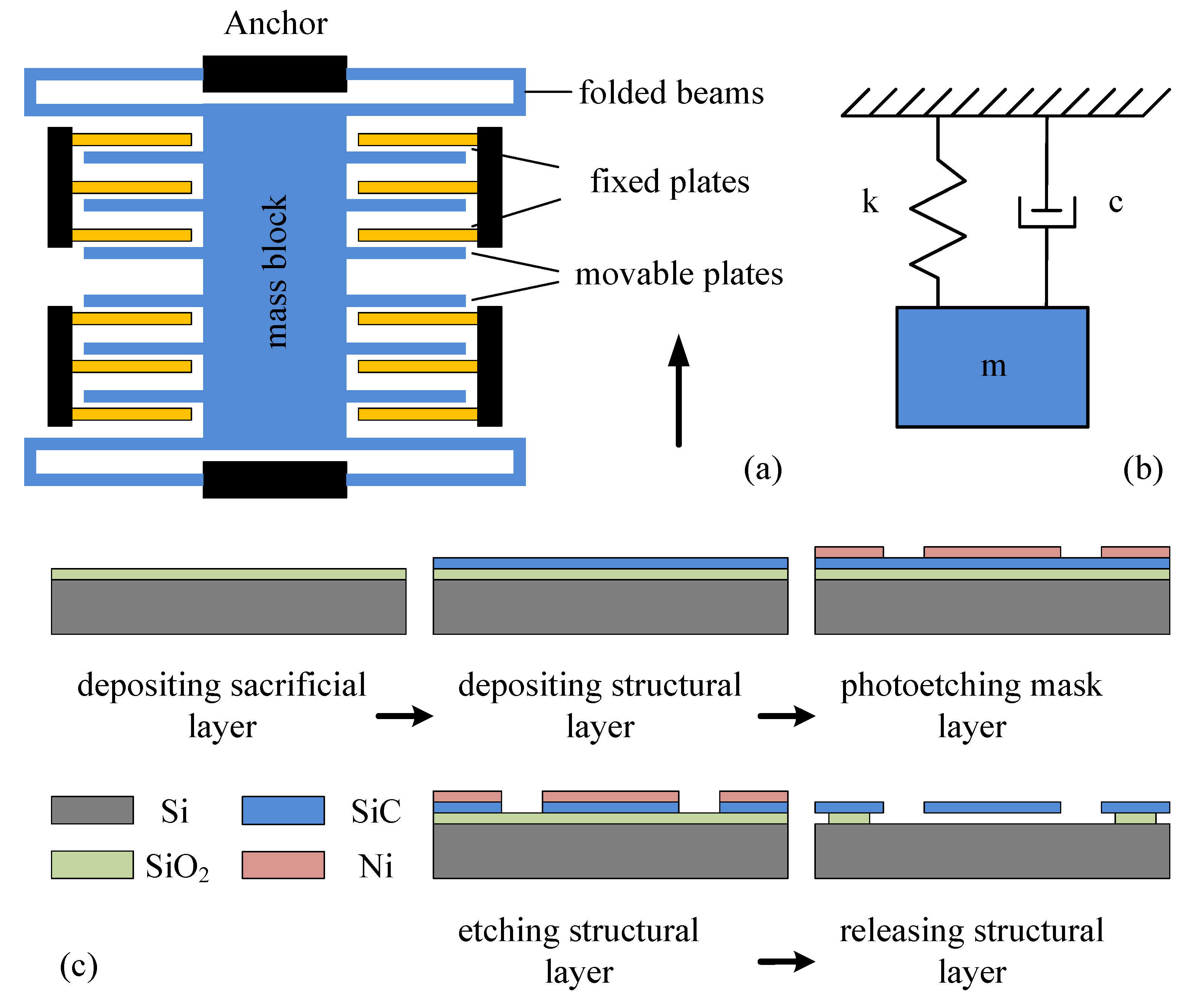
Figure 1a shows the structural model of a single-axis, comb-type capacitive micro-accelerometer consisting mainly of a sensitive mass block with comb fingers, fixed electrode plates, and two pairs of folded support beams. The middle part is the mass block, which is fixed on the substrate by four thin beams. The mass block can move freely along the direction perpendicular to the thin beams. The comb fingers extend from both sides of mass block, and each comb finger is a movable electrode plate of the variable capacitor. The fixed electrode plates and the movable electrode plates are arranged alternately, and they form differential detection electrodes.
When the system is accelerated, the mass block is subjected to inertial force, and has a certain displacement in the acceleration–detecting direction. Then, the displacement is converted into capacitance changes on the capacitive plates, and the acceleration value can be obtained by measuring the capacitance changes.
Figure 1c shows the process flow of the accelerometer. First, a low-temperature oxidation (LTO) sacrificial layer is deposited on the silicon substrate, which not only releases the structure, but also ensures the insulation between the electromechanical structure and the substrate. Second, silicon carbide is deposited as a structural layer by low-pressure chemical vapor deposition (LPCVD) technique. Third, the nickel mask layer is formed by the stripping process for the next etching process. Fourth, the structural layer is processed by inductively coupled plasma (ICP) etching. Finally, the wafer is placed in an HF solution for wet etching to release the structure.
2.2. Modeling of the Capacitive Accelerometer
According to Newton’s second law, this kind of micromachined accelerometer can be equivalent to a second-order mass-spring-damping model, as shown in Figure 1b. Its differential equation is shown below [44]:
where is the mass of the sensitive mass block; is the viscous damping coefficient of the system; is the stiffness coefficient of the system; is the displacement of the mass block; is the acceleration of the measured object; and is time.
In addition, the natural frequency of the accelerometer is and the relative damping ratio of the accelerometer is .
2.3. Parameter Setting of the Capacitive Accelerometer
It is relatively easy to calculate the mass of the micro-accelerometer. Assuming that the density of the material is , the surface area of the structure is , and the thickness of the structure is , the mass of the whole structure is
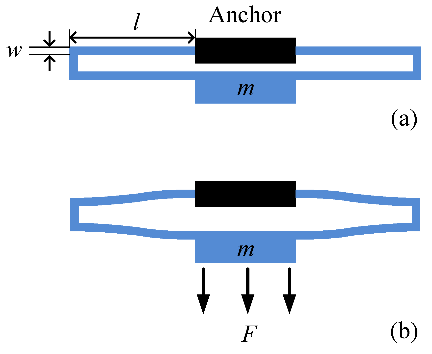
The stiffness of the micro-accelerometer is provided by four folded beams, the length and width of which are and , respectively, as shown in Figure 2a. When the micro-accelerometer is moved upwards, the mass block is subjected to a downward inertial force . The deformation diagram of a pair of folded support beams is shown in Figure 2b.
According to the principle of material mechanics, the stiffness coefficient of the micro-accelerometer can be described as [45]
where is the elastic modulus of the material.
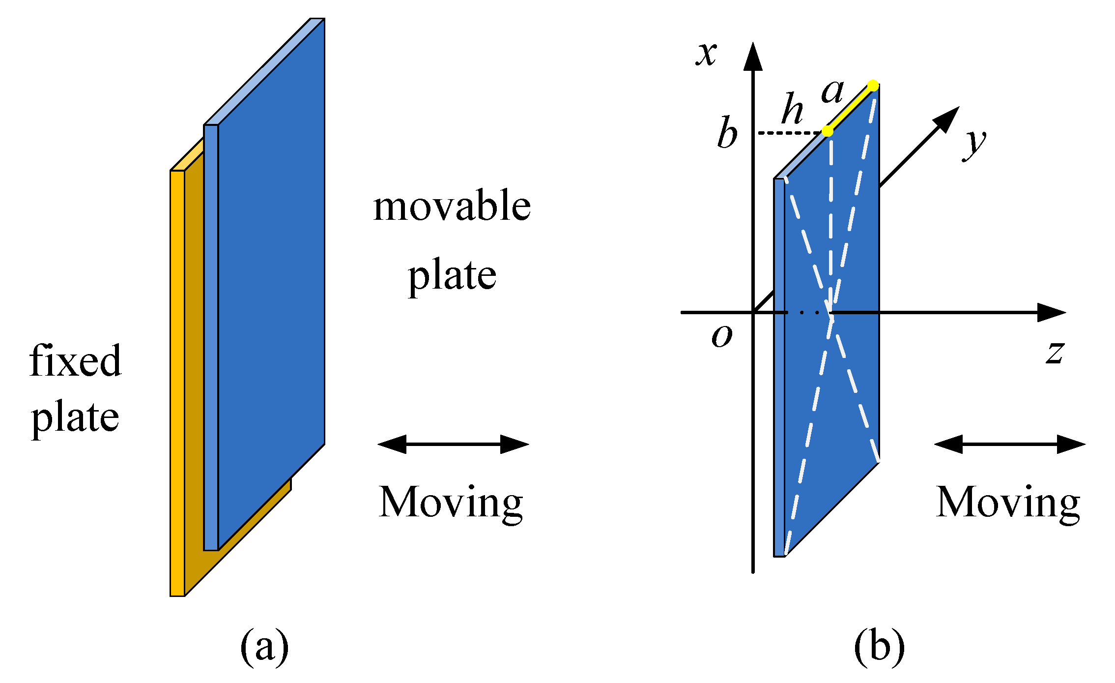
The damping of the MEMS accelerometer usually includes structural damping and air damping between moving parts. Under normal working conditions, structural damping is much lower than air damping, so it can be ignored. Air damping can be divided into squeeze-film air damping and slide-film air damping. For the capacitive accelerometer in this article, when it is accelerated, due to the existence of inertial force, the mass block with movable electrode plates undergoes a small displacement, resulting in capacitance changes. At this moment, the movable electrode plates move towards the fixed electrode plates, as shown in Figure 3a, and the air in the gaps between them is squeezed. The air acts as a damper, and it hinders the motion of the moving plates. Additionally, the movable plates may move away from the fixed plates, and the air between them also hinders the movements of the moving plates. This kind of damping is called squeeze-film air damping. In this process, the force that hinders the motion of the plate due to the viscous effect is the viscous damping force. However, when the vibration frequency of a movable plate is higher, there is not enough time for the air between the plates to flow out, and the elastic damping force hinders the motion of the plate. In addition, when the sensitive mass block vibrates up and down, as shown in Figure 1a, the upper and lower surfaces of the mass block are subjected to air friction forces; this is called slide-film air damping. In this case, squeeze-film damping has a far greater effect than slide-film damping, so we only consider the effect of the squeeze-film damping on the dynamic characteristics of the accelerometer.
Suppose that the plate is parallel to the other plate in the x–y plane of a Cartesian coordinate system, as shown in Figure 3b, and the dimensions of the plates are much larger than the distance between them. In this case, the effect of squeeze-film air damping can be expressed by the Reynolds equation [46]:
where is the air density, is the gap distance between two plates, is the viscosity coefficient of air, is the air pressure between the plates, are the space coordinate components, and is time.
When the movable plate vibrates with the displacement of , the viscous damping force and elastic damping force on the movable plate can be obtained by solving Equation (4) [47]
where is the plate length; is the plate width; is the aspect ratio of the plate; is the initial gap distance between the plates; is the air pressure between the plates under the initial conditions; is the squeeze number; and and are constants:
3. Structural Design and Optimization
The physical model of the capacitive accelerometer was established by Ansys, and the initial values of the structural parameters are listed in Table 1.
3.1. Modal Analysis
The elastic microbeam is a key part of the micro-accelerometer, and is closely related to the sensitivity and range of the sensor. It also has an important impact on dynamic performance.
In the design of the micro-accelerometer, modal analysis, including natural frequencies and mode shapes, should be considered first. According to the analysis results, reasonable size-matching of the elastic beam was obtained, and could be used to widen the gap between the natural frequency in the sensitive direction (the direction of the acceleration to be measured) and that of the non-sensitive direction to improve sensitivity and resolution.
3.1.1. Modal Analysis of the Micro-Accelerometer
In the modal analysis, it was assumed that the density, Young’s modulus, and Poisson’s ratio of silicon carbide were 3200 kg/m3, 4.3 × 10¹¹ Pa, and 0.17 [48], respectively. With this in mind, a modal analysis of the capacitive micro-accelerometer with folded support beams fixed on the anchors was carried out. The analysis results are shown in Figure 4. The accelerometer has six main modes, including natural frequencies and mode shapes in six degrees of freedom. As can be seen from the mode shape in Figure 4a, the first mode is the translational motion along the x-axis, which is sensitive to external acceleration, so it needs to be strengthened. Figure 4b,c shows that the second and third modes are the non-sensitive vibration modes that move along the y axis and z-axis, respectively, so they need to be suppressed. Similarly, as shown in Figure 4d–f, the fourth, fifth, and sixth modes are the rotational motions around the y-axis, z-axis, and x-axis, respectively, and they also need to be suppressed. The natural frequencies from the first mode to the sixth mode of the accelerometer were 2422.1; 19,977; 24,412; 26,418; 36,001; and 41,181 Hz, respectively.
3.1.2. Optimization of the Structural Parameters
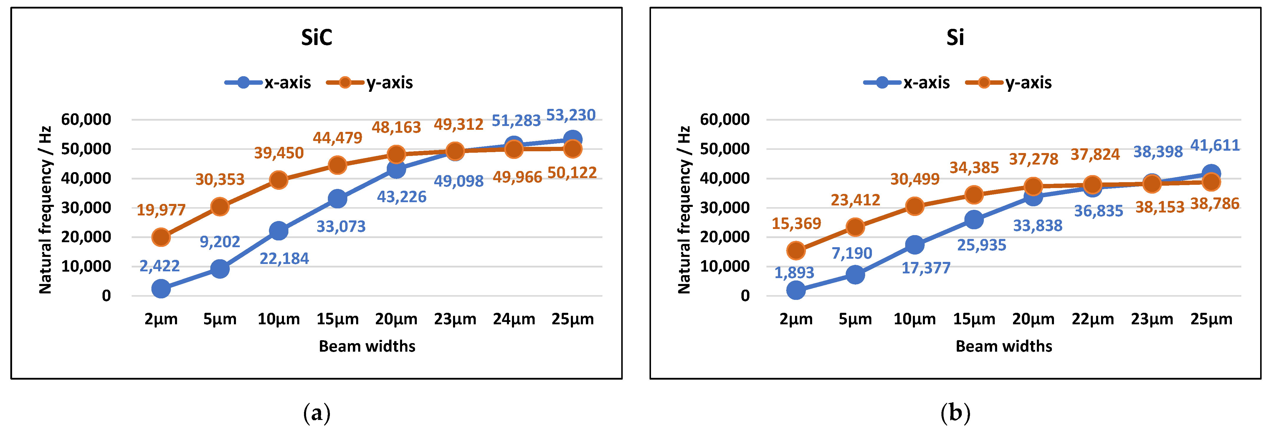
Modal analysis of the accelerometer with different widths of the folded support beams was also carried out, and the results showed that the width of the folded beams had an important effect on the natural frequency and mode shape of the accelerometer. As illustrated in Figure 5a, the natural frequency in any order mode of the SiC-based accelerometer increased with an increase in beam width. When the beam-width ranged from 2 to 23 μm, the motion moving along the x-axis is always the first-order mode shape, and the motion moving along the y-axis is always the second-order. However, when the beam width is more than 23 μm, the order of vibration modes changes; the motion moving along the y-axis becomes the first-order mode shape, and the motion moving along the x-axis becomes the second-order. At this time, when the accelerometer is excited, it will vibrate along the y-axis first. However, the y-axis is not the sensitive direction of the accelerometer, so it is not conducive to the normal measurement of external accelerations.
It can also be seen in Figure 5a that, with an increase in the width of the folded beam, the natural frequency of the first-order mode gradually approaches that of the second-order mode. That is, the thicker the beam width, the more easily cross-coupling occurs. When the accelerometer vibrates along the x-axis, an increase in beam width will also cause vibrations along the y-axis, and this is not supported in the design of the micro-accelerometer. Therefore, to reduce the cross-coupling of the x and y axes, the width of the folded beam should be much smaller than 23 μm. According to the above analysis, the width of the beam should be 4 μm, so that the accelerometer achieves the two advantages of a large range and low cross-coupling at the same time.
As shown in Figure 5b, similar results also appeared in the modal analysis of the silicon-based accelerometer with the same structure, in which it was assumed that the density, Young’s modulus, and Poisson’s ratio of silicon in the (111) direction were 2330 kg/m3, 1.9 × 10¹¹ Pa, and 0.28, respectively [49]. The natural frequency in any order mode increased with an increase in beam width. When the beam width ranged from 2 to 22 μm, the motion moving along the x-axis was the first mode. However, if the beam width was more than 22 μm, the motion moving along the y-axis became the first mode. The thicker the beam width, the more easily cross-coupling occurred.
3.1.3. Modal Comparison between the SiC-Based Structure and the Si-Based Structure
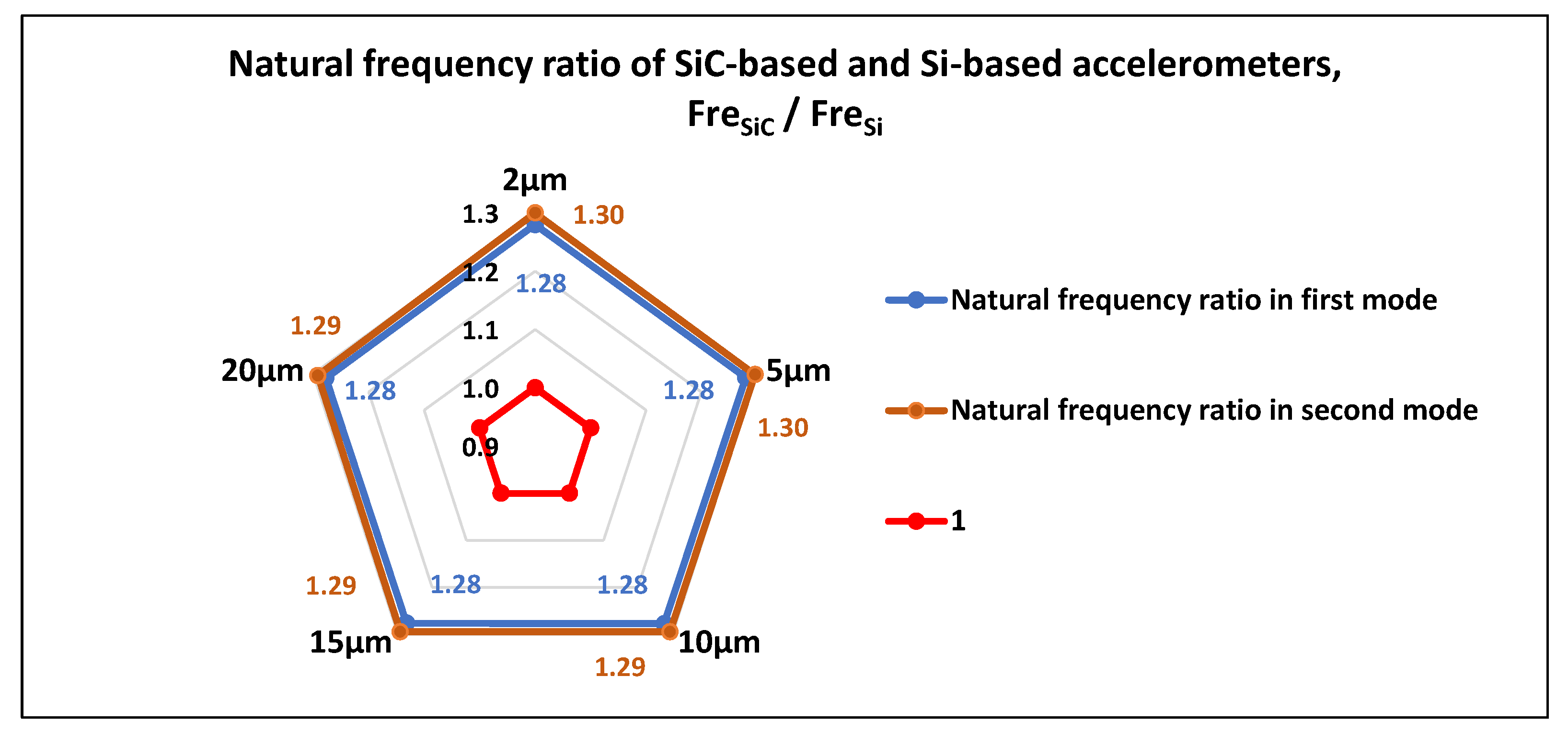
We also compared the natural frequencies in the first two modes of the SiC-based accelerometer with those of the Si-based accelerometer with the same structure, as shown in Figure 6. The results show that when the beam width ranged from 2 to 20 μm, the ratios of the first-order natural frequency of the two accelerometers () were always equal to 1.28, and the ratios of the second-order natural frequency were approximately equal to 1.29. Therefore, the SiC-based accelerometer has a higher natural frequency than the silicon(111) accelerometer with the same structure. A high natural frequency not only effectively avoids the resonance of the structure, which may cause structural damage, but also broadens the working frequency range of the accelerometer.
3.2. Dynamic Characteristic Analysis
Damping is an important parameter affecting the dynamic performance of the micro-accelerometers. For some accelerometers, the damping characteristics directly determine their working frequency ranges and dynamic accuracies.
3.2.1. Squeeze-Film Air Damping
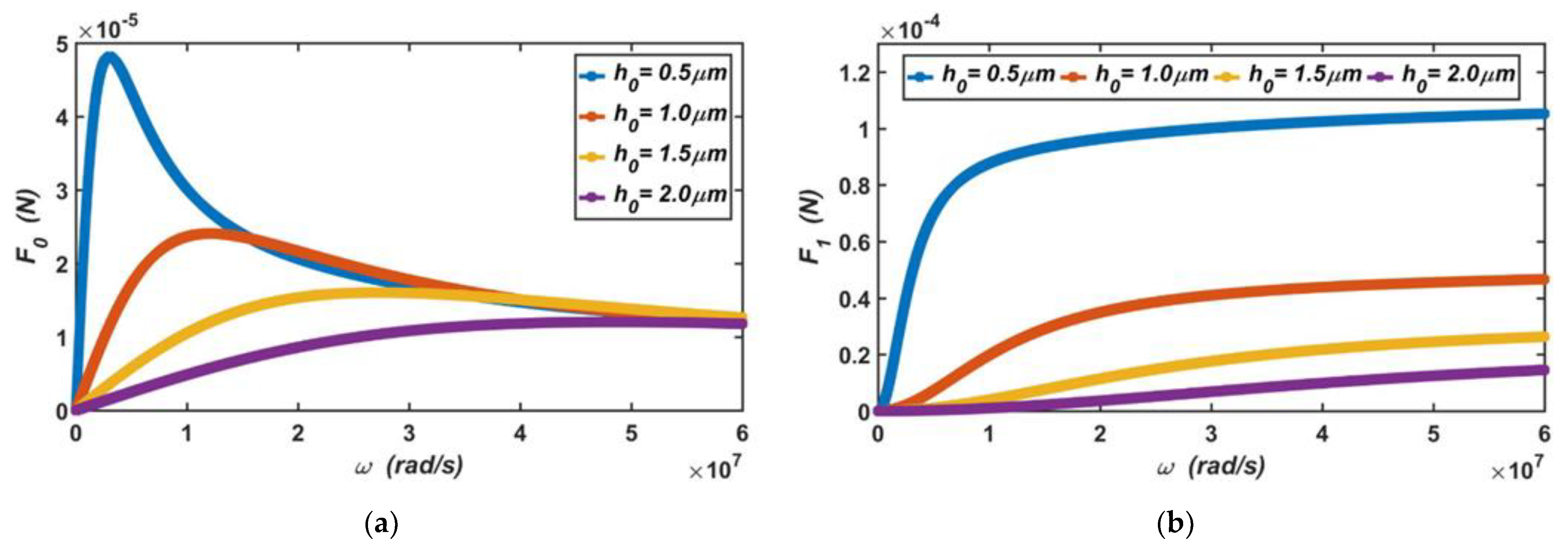
In the accelerometer, it was assumed that the vibration amplitude of the moving plate was . According to Equations (5) and (6), when the gap between the capacitive plates ranges from 0.5 to 2 μm, the dependence of the viscous damping force produced by the air film on the vibration frequency is shown in Figure 7a, and the dependence of the elastic damping force on the vibration frequency is shown in Figure 7b.
It can be seen from the curves in the two figures that when the vibration frequency of the moving plate was low, the viscous damping force of the air film increased linearly with an increase in the vibration frequency, and the elastic damping force increased slowly. When the vibration frequency was higher than a certain value, the viscous damping force of the air film decreased with an increase in the vibration frequency, but the elastic damping force increased rapidly. These results show that when the moving plate vibrates, damping is the main form of air film at a low frequency, and stiffness is the main form of air film at a high frequency. In this capacitive accelerometer, due to its low vibration frequency in operation, viscous damping force is the main source of the damping.
3.2.2. Analysis in the Frequency Domain
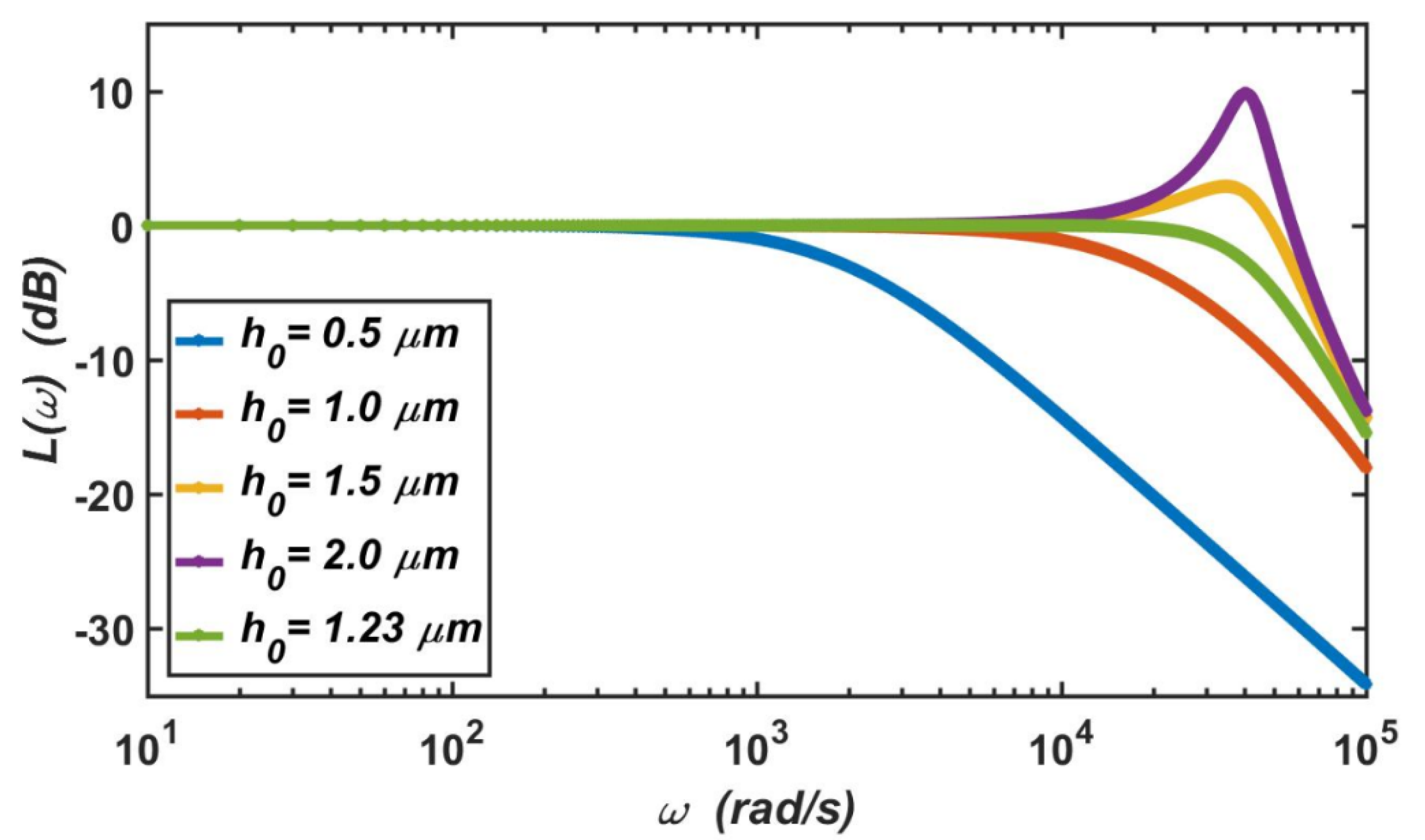
The logarithmic amplitude–frequency characteristics of the micro-accelerometer can be expressed as
where represents the vibration frequency of the micro-accelerometer, and represents the natural frequency of the micro-accelerometer. is the damping ratio of the system.
Figure 8 shows the amplitude–frequency characteristics of the micro-accelerometer at standard atmospheric pressure, which are only determined by the relative damping ratio of the system. It can be seen from the figure that when the gap between the capacitive plates was or , the relative damping ratios were and , respectively, and the system was in the state of overdamping. At this time, the amplitude–frequency curve had no resonant peak, but the working bandwidth was narrow. When the gap between the capacitive plates was or , the relative damping ratios were and , respectively, and the system was in the state of underdamping. At this time, the bandwidth of the capacitive accelerometer was large. However, when the external vibration frequency approached its natural frequency, the accelerometer will resonate, and its vibration amplitude will become very large. In this case, the system may be damaged; this outcome is not supported in the design of the accelerometer. Therefore, the most appropriate damping ratio of the system is , at which the micro-accelerometer achieves two advantages at the same time. The first is that it has a large working bandwidth, and the second is that its amplitude-frequency curve has no resonant peak. Based on this, the gap between the capacitive plates should be .
3.2.3. Analysis in the Time Domain
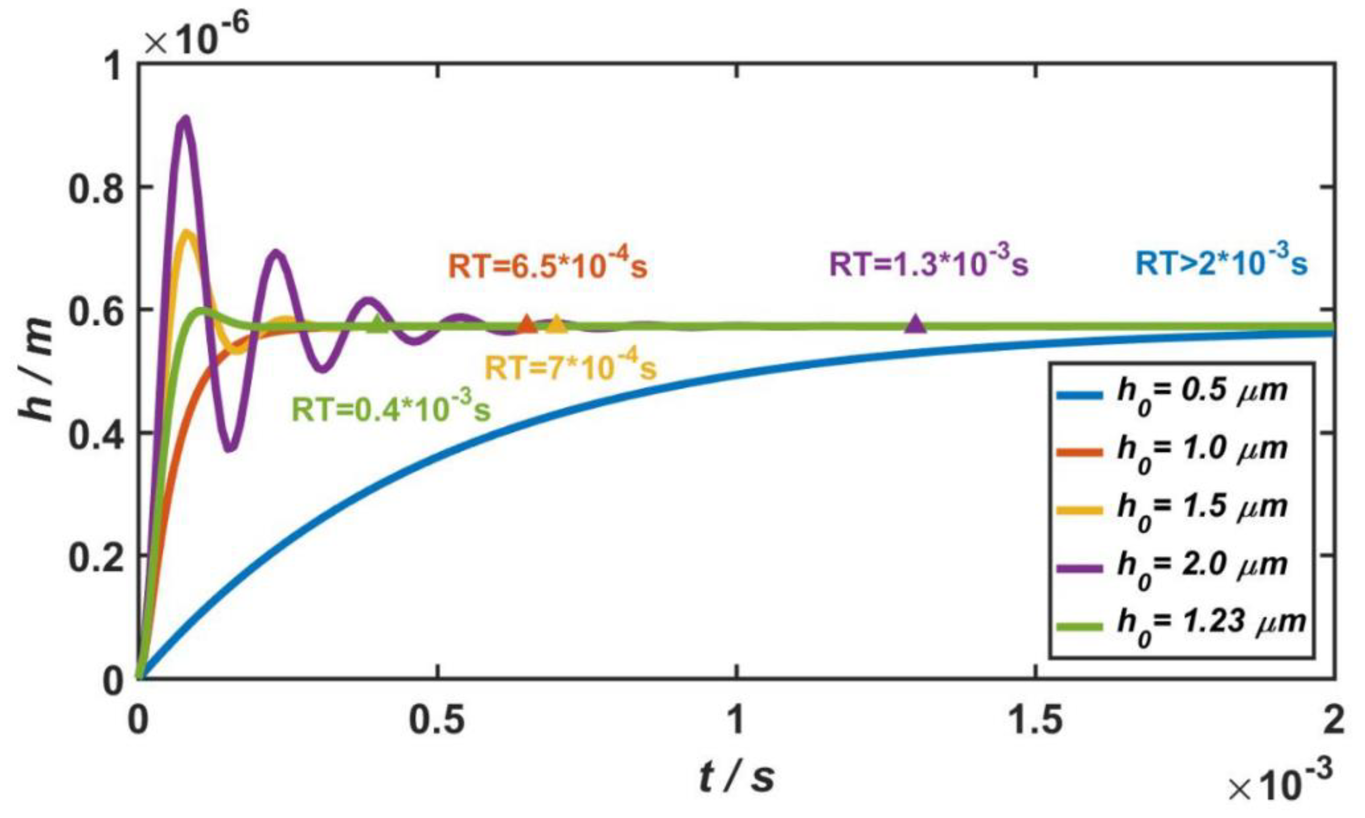
As mentioned in Section 2.2, the micro-accelerometer could be equivalent to a second-order damping system. When the external acceleration was a = 100 g, the step response of the micro-accelerometer is shown in Figure 9. If the system is in the state of over-damping, the smaller the damping ratio of the system, the shorter the response time (RT) of the system. As shown by the blue and red curves in Figure 9, when the gap between the capacitive plates was or , the relative damping ratios were and , and the response times were s and s, respectively. However, in the case of underdamping, the greater the damping ratio of the system, the shorter the response time. As shown by the yellow and purple curves in Figure 9, when the gap between the capacitive plates was or , the relative damping ratios were and , and the response times were s and s, respectively.
In general, when the relative damping ratio of the micro-accelerometer is , the dynamic characteristics of system are at their best. The system responds quickly, and a stable output value can be achieved in a short period of time. Therefore, in the design of the micro-accelerometer, if there are no other constraints, the damping ratio of the structure should be to ensure the optimal dynamic characteristics of the system. In this case, for the capacitive accelerometer in this paper, the gap between the movable and fixed electrode plates should be . Based on this, the step response of the micro-accelerometer is shown by the green curve in Figure 9, and the response time is s.
4. Performance Characterization
After the structural parameters of the accelerometer were optimized and determined, its performance characteristics could be obtained through FEM simulations.
4.1. Scale Range
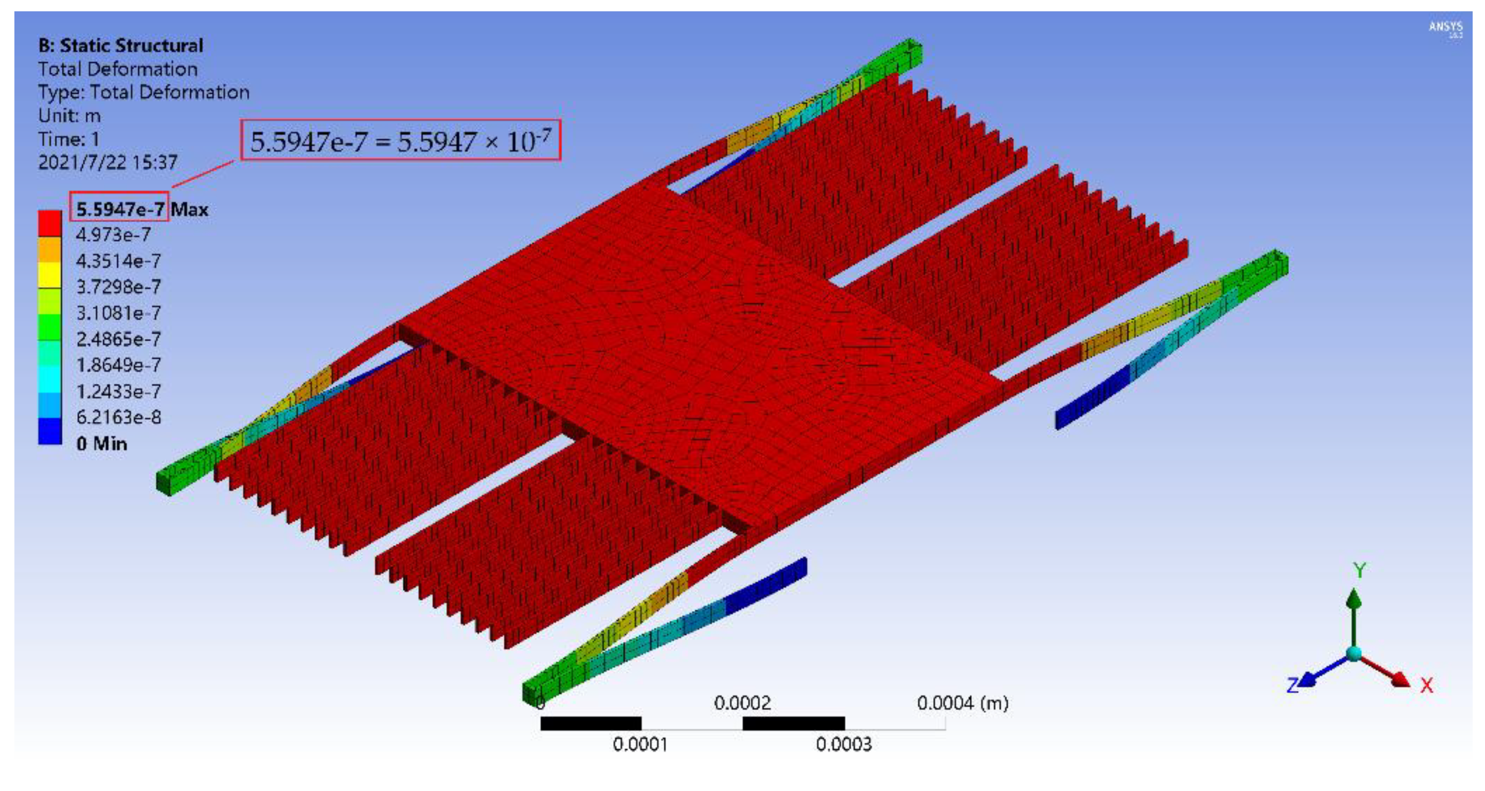
First, mechanical analysis of the accelerometer was carried out at room temperature. Figure 10 shows the total deformation of the accelerometer under the acceleration of 100 g along the x-axis. The final displacement of the mass block with the moving plates was 0.559 μm, which was less than the gap distance between the moving and fixed electrode plates (), so the accelerometer will not be damaged during operation.
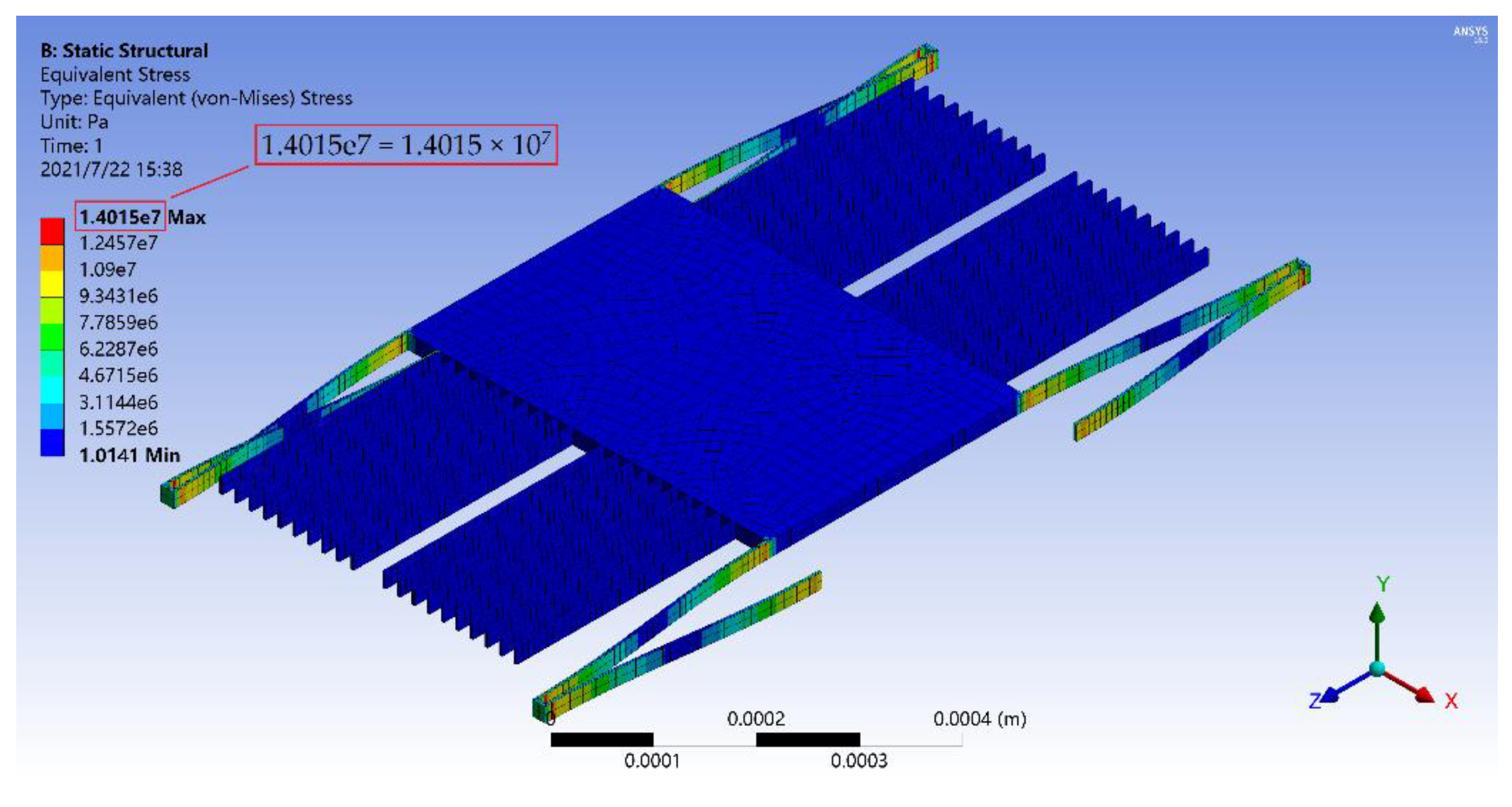
Then, structural strength analysis of the accelerometer was carried out at room temperature. Figure 11 shows the stress distribution of the accelerometer under the acceleration of 100 g along the x-axis. It can be seen that large stresses existed at the connection between the folded beam and the mass block, the connection between the folded beam and the anchor and the corner of the folded beam, but its maximum value (14.015 MPa) was much less than the flexural strength of silicon carbide (359 MPa). Therefore, under a large acceleration, the structure could still maintain a good shape without fracturing.
Based on the above analysis, the accelerometer can effectively meet the measurement requirements of the acceleration range from 0 to 100 g. In addition, the silicon(111) accelerometer with the same structure was also simulated, and its scale range was 0 to 61 g. Therefore, the range of the SiC-based accelerometer was 1.64 times of that of the silicon(111) with the same structure.
4.2. Sensitivity
The mechanical sensitivity of the accelerometer is one of the important indexes that which represents the corresponding displacement generated by the acceleration per unit. Ten groups of simulation experiments under different accelerations were made at room temperature, and the experiment results are shown in Table 2. The relationship between the displacement and the acceleration was plotted as Figure 12, and it could be derived from linear regression as follows:
Therefore, the sensitivity of the accelerometer () was 0.0056 μm/g.
4.3. High-Temperature Performances
Silicon carbide is an attractive material for high-temperature semiconductor devices, so dozens of FEM simulations, including mechanical analysis and structural strength analysis, were made to get the thermal performances of the accelerometer at high temperatures. The material properties of silicon carbide at different temperatures are shown in Table 3 [50], and it can be seen from it that the density, elastic modulus, and Poisson’s ratio of silicon carbide decrease with the increase in temperature. Therefore, the mass, the stiffness coefficient, and other parameters of the accelerometer will change accordingly.
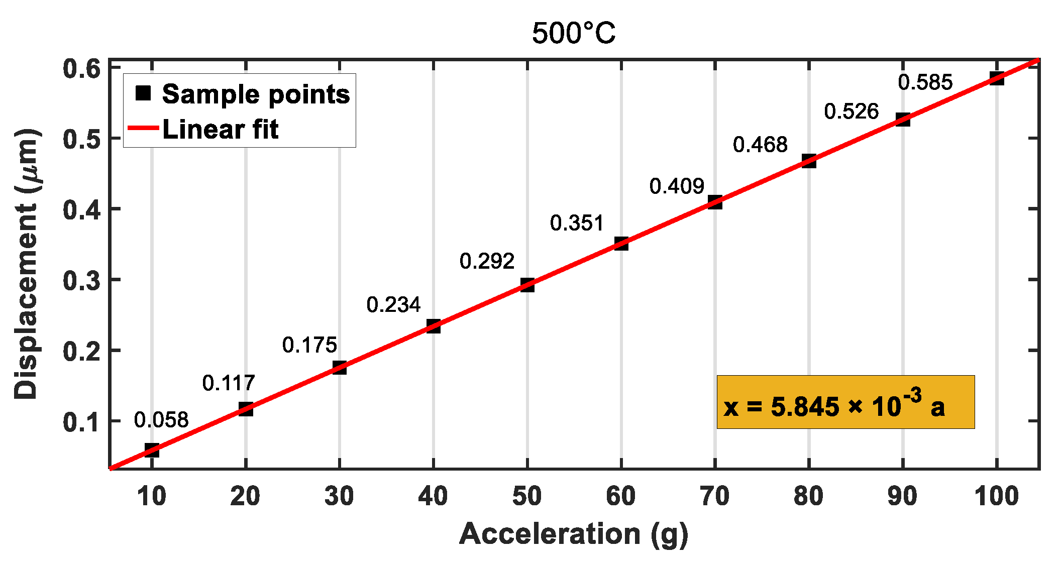
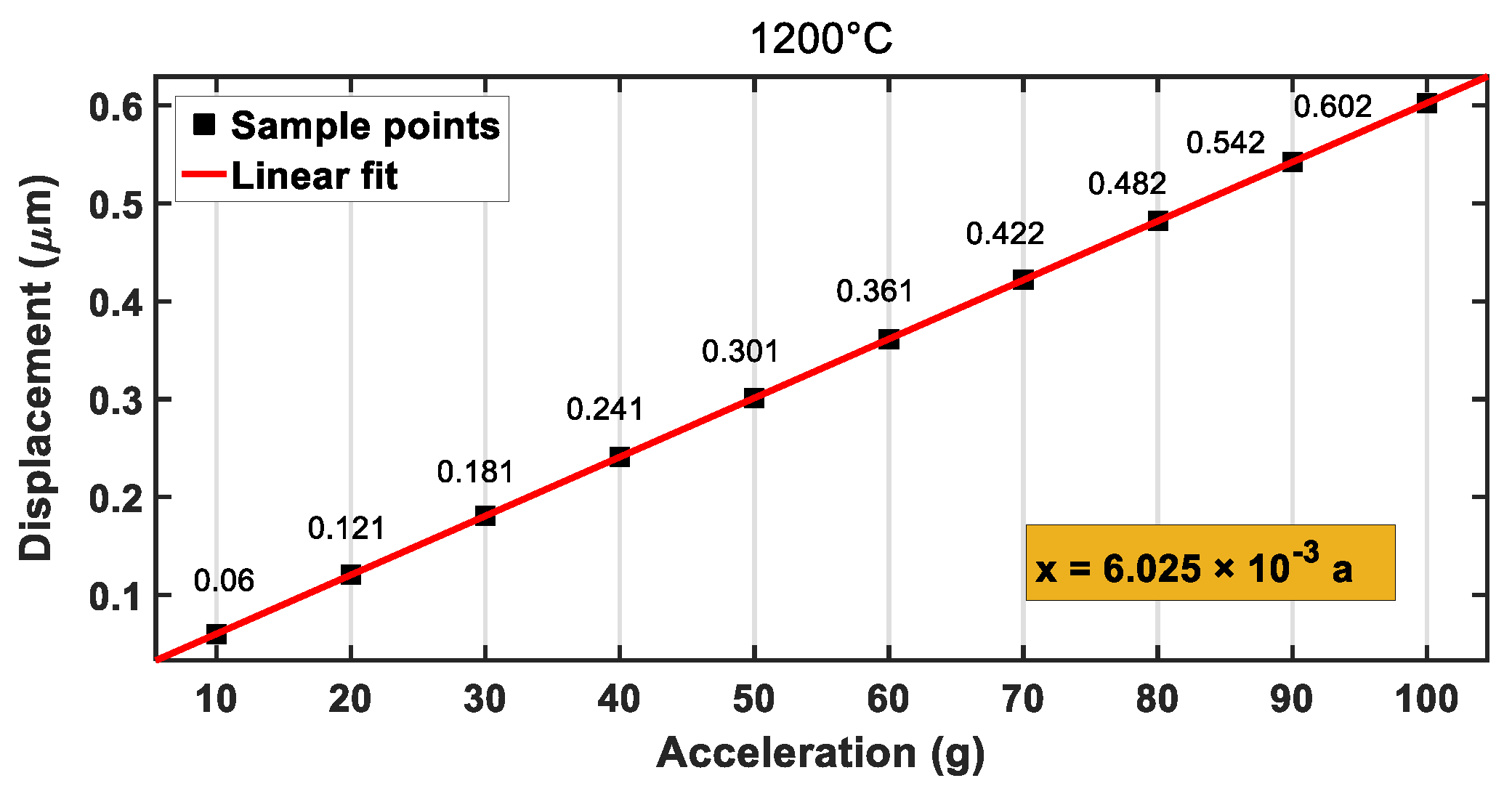
In the mechanical analysis, characteristic parameters of silicon carbide at different temperatures (see Table 3) were set in Ansys. Then, the temperature of the accelerometer was set to the corresponding value (500, 1000, 1200 °C). In the case, the dependences of the displacements of the accelerometer on the external accelerations at 500, 1000, and 1200 °C are shown in Figure 13, Figure 14 and Figure 15, respectively. When the temperature was increased to 500, 1000, or 1200 °C, the final deformations of the accelerometer were 0.585, 0.597, and 0.602 μm, respectively, under the external acceleration of a = 100 g, which was less than the gap distance between the moving and fixed electrode plates (). After the linear fitting of the sample points, the mechanical sensitivities of the accelerometer were 0.0058, 0.0059, and 0.0060 μm/g, respectively. By comparing the sensitivities of the accelerometer at different temperatures, it was found that the sensitivities increased with the increase in temperature, but the change was not very notable, which was conducive to the measurement of the accelerometer at high temperatures. Therefore, the SiC-based accelerometer had the advantage of low temperature sensitivity, which leads to high reliability.
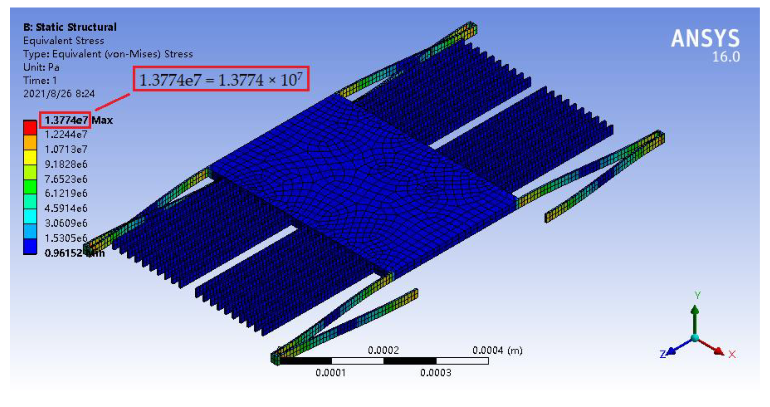
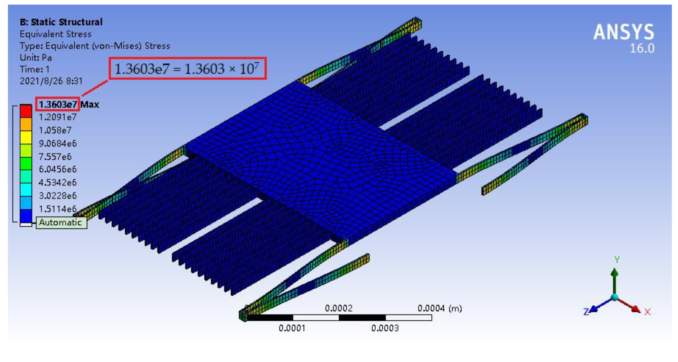
In the structural strength analysis, its parameter setting and temperature setting were similar to those in the mechanical analysis. In the case, when the external acceleration was a = 100 g, the maximum stresses of the accelerometer at 500, 1000, and 1200 °C were 13.774, 13.646, and 13.603 MPa, respectively, as illustrated in Figure 16, Figure 17 and Figure 18, which were far less than the flexural strengths of silicon carbide at high temperatures (see Table 3).
Therefore, the accelerometer could still effectively meet the measurement requirements of the acceleration range from 0 to 100 g at high temperatures.
5. Discussion
As could be seen from this article, the process flow and the working principle of the capacitive accelerometer based on a silicon carbide microstructure was introduced. Through the modal analysis of the micro-accelerometer, the structural parameters of the elastic microbeam were optimized. This not only placed the sensitive mode in the first vibration mode, but also widened the frequency difference between the first vibration mode and other vibration modes to avoid cross-coupling. It was found that the ratio of the natural frequency in each mode of the SiC-based accelerometer, compared to that of a silicon(111) accelerometer with the same structure, was approximately equal to 1.3, so the SiC-based accelerometer has a higher natural frequency. This means it can not only effectively avoid the resonance of the structure, which may cause structural damage, but also broaden the working frequency range of the accelerometer.
It is well known that squeeze-film air damping is produced between the moving and fixed electrode plates when the micro-accelerometer vibrates. We found that when the vibration frequency was low, the viscous damping force of the air film increased linearly with the increase in vibration frequency, and the elastic damping force increased slowly. When the vibration frequency was high, the viscous damping force of the air film decreased with the increase in vibration frequency, but the elastic damping force increased rapidly.
The second-order linear system of the accelerometer was analyzed in the frequency domain, and its amplitude-frequency characteristics showed that the accelerometer obtained two simultaneous advantages when the relative damping ratio is 0.7. One is a large working bandwidth, and the other is an amplitude-frequency curve that had no resonant peak. In this case, the gap between capacitive plates should be 1.23 μm. The second-order system of the accelerometer was also analyzed in the time domain, and its step response showed that, when the damping ratio of the micro-accelerometer was 0.7, the system responded quickly, and a stable output value could be achieved in a short period of time. In this case, when the external acceleration was a = 100 g, the response time of the accelerometer was 0.4 ms.
The range of this accelerometer was from 0 to 100 g, and the range of a silicon(111) accelerometer with the same structure was from 0 to 61 g. Therefore, the range of the SiC-based accelerometer is 1.64 times of that of silicon(111) accelerometer. When the temperature was increased to 500, 1000, or 1200 °C, the mechanical sensitivities of the accelerometer were 0.0058, 0.0059, and 0.0060 μm/g, respectively, and it could be seen from it that the sensitivities increased with the increase in temperature, but the change was not very notable. Therefore, the SiC-based accelerometer had the advantage of low temperature sensitivity, which leads to high reliability of the device. It is worth noting that, although the theory presented in this study did not account for all the ground truth of silicon and silicon carbide, the results provided great potential for the application of SiC-based accelerometers.
6. Conclusions
In this study, a capacitive accelerometer based on a silicon carbide microstructure was designed and investigated by FEM. It had many advantages, such as low cross-coupling and good dynamic characteristics. Compared to a silicon(111) accelerometer with the same structure, it had a higher natural frequency, a wider range, and a higher working temperature of up to 1200 °C. Therefore, this research effectively validated the advantages of a capacitive accelerometer based on the silicon carbide microstructure over conventional silicon devices in the field of MEMS inertia measurement.
Author Contributions
Conceptualization, X.T. and W.S.; methodology, X.T. and Z.G.; software, X.T. and W.X.; writing—original draft preparation, X.T.; writing—review and editing, X.T.; supervision, R.T. All authors have read and agreed to the published version of the manuscript.
Funding
This research was supported by National Natural Science Foundation of China (NSFC), grant number 61274117.
Institutional Review Board Statement
Not applicable.
Informed Consent Statement
Not applicable.
Data Availability Statement
Not applicable.
Conflicts of Interest
The authors declare no conflict of interest.
References
- He, D. Testing Research of Pendulous Integrating Gyro Accelerometer on Low-Frequency Linear Vibrator. Ph.D. Thesis, The First Academy of China Aerospace Science and Technology Corporation, Beijing, China, 2019. [Google Scholar]
- Haeussermann, W.; Mueller, F.; Hopkins, R. The pendulous integrating gyroscope accelerometer (PIGA) from the V-2 to trident D5, the strategic instrument of choice. In AIAA Guidance, Navigation, and Control Conference and Exhibit; American Institute of Aeronautics and Astronautics: Reston, VA, USA, 2001. [Google Scholar]
- Keating, G.M.; Bougher, S.W.; Zurek, R.W.; Tolson, R.H.; Cancro, G.J.; Noll, S.N.; Parker, J.S.; Schellenberg, T.J.; Shane, R.W.; Wilkerson, B.L.; et al. The structure of the upper atmosphere of Mars: In Situ accelerometer measurements from Mars global surveyor. Science 1998, 279, 1672–1676. [Google Scholar] [CrossRef] [Green Version]
- Bacon, B.; Ostroff, A.; Joshi, S. Reconfigurable NDI controller using inertial sensor failure detection & isolation. IEEE Trans. Aerosp. Electron. Syst. 2001, 37, 1373–1383. [Google Scholar] [CrossRef]
- Wang, C.; Chen, F.; Wang, Y.; Sadeghpour, S.; Wang, C.; Baijot, M.; Esteves, R.; Zhao, C.; Bai, J.; Liu, H.; et al. Micromachined accelerometers with sub-μg/√Hz noise floor: A review. Sensors 2020, 20, 4054. [Google Scholar] [CrossRef]
- Lowrie, C.; Desmulliez, M.P.; Hoff, L.; Elle, O.J.; Fosse, E. Fabrication of a MEMS accelerometer to detect heart bypass surgery complications. Sens. Rev. 2009, 29, 319–325. [Google Scholar] [CrossRef]
- Wang, C.-K.; Chen, C.-S.; Wen, K.-A. A monolithic CMOS MEMS accelerometer with chopper correlated double sampling readout circuit. In Proceedings of the 2011 IEEE International Symposium of Circuits and Systems (ISCAS), Rio de Janeiro, Brazil, 15–18 May 2011; pp. 2023–2026. [Google Scholar]
- Li, Z.; Yang, W.; Xiong, X.; Wang, Z.; Zou, X. Viaxl: A solution of a low-cost real-time visual accelerometer based on laser speckle optical flow detection. Sensors 2020, 20, 7033. [Google Scholar] [CrossRef] [PubMed]
- Barlian, A.A.; Park, W.-T.; Mallon, J.R.; Rastegar, A.J.; Pruitt, B.L. Review: Semiconductor piezoresistance for microsystems. Proc. IEEE 2009, 97, 513–552. [Google Scholar] [CrossRef] [Green Version]
- Zhang, G.J.; Xu, J.; Li, J.; Wang, X.Y.; Zhang, W.D. Design of double t-shape accelerometer based on MEMS. In Proceedings of the 2nd International Conference on Material and Manufacturing Technology (ICMMT 2011) Progress Meeting of the Royal-Society-of-Tropical-Medicine-and-Hygiene’s Annual Research, Xiamen, China, 8–10 July 2011. [Google Scholar]
- Culhane, K.M.; O’Connor, M.; Lyons, D.; Lyons, G.M. Accelerometers in rehabilitation medicine for older adults. Age Ageing 2005, 34, 556–560. [Google Scholar] [CrossRef] [Green Version]
- Chang, H.; Xie, J.; Fu, Q.; Shen, Q.; Yuan, W. Micromachined inertial measurement unit fabricated by a SOI process with selective roughening under structures. Micro Nano Lett. 2011, 6, 486–489. [Google Scholar] [CrossRef]
- Chen, L.; Li, L.; Zhan, L.; Chen, Q.; He, X.; Yu, H.; Zhou, W. Investigation of drift phenomena in closed-loop capacitive micro accelerometers. J. Micromechanics Microengineering 2020, 30, 095009. [Google Scholar] [CrossRef]
- Liu, S.Q.; Zhang, J.C.; Zhu, R. A Wearable human motion tracking device using micro flow sensor incorporating a micro accelerometer. IEEE Trans. Biomed. Eng. 2020, 67, 940–948. [Google Scholar] [CrossRef]
- Roylance, L.; Angell, J. A batch-fabricated silicon accelerometer. IEEE Trans. Electron Devices 1979, 26, 1911–1917. [Google Scholar] [CrossRef]
- Dong, J. Introduction. In Inertial Instruments: Micromachined Accelerometer; Tsinghua University Press: Beijing, China, 2003; pp. 1–20. [Google Scholar]
- Edmonds, L.; Swift, G.; Lee, C. Radiation response of a MEMS accelerometer: An electrostatic force. IEEE Trans. Nucl. Sci. 1998, 45, 2779–2788. [Google Scholar] [CrossRef]
- Seo, A.; Uda, S. Trunk rotation monitor using angular velocity sensors. Ind. Health 1997, 35, 222–228. [Google Scholar] [CrossRef]
- Tosserams, S.; Etman, L.F.P.; Rooda, J.E. A micro-accelerometer MDO benchmark problem. Struct. Multidiscip. Optim. 2010, 41, 255–275. [Google Scholar] [CrossRef] [Green Version]
- Zhang, H.; Wang, Y.; Wang, Y.; Soon, P.L. Design and realization of two-wheel micro-mouse diagonal dashing. J. Intell. Fuzzy Syst. 2016, 31, 2299–2306. [Google Scholar] [CrossRef]
- Warren, K. Electrostatically force-balanced silicon accelerometer. Navig. J. Inst. Navig. 1991, 38, 91–99. [Google Scholar] [CrossRef]
- Wang, Y.; Zhao, X.; Wen, D. Fabrication and characteristics of a three-axis accelerometer with double L-shaped beams. Sensors 2020, 20, 1780. [Google Scholar] [CrossRef] [PubMed] [Green Version]
- Chen, Z.-H.; Li, C.-Y.; Chu, S.-Y.; Tsai, C.-C.; Wang, Y.-H.; Kao, H.-Y.; Wei, C.-L.; Huang, Y.-H.; Hsiao, P.-Y.; Liu, Y.-H. The design of aluminum nitride-based lead-free piezoelectric MEMS accelerometer system. IEEE Trans. Electron Devices 2020, 67, 4399–4404. [Google Scholar] [CrossRef]
- Zhang, H.; Chen, D.; Pandit, M.; Sun, J.; Zhao, C.; Seshia, A. Amplitude-modulated resonant accelerometer employing parametric pump. Appl. Phys. Lett. 2020, 117, 163504. [Google Scholar] [CrossRef]
- Chen, D.; Yin, L.; Fu, Q.; Zhang, Y.; Liu, X. Measuring and calibrating of the parasitic mismatch in MEMS accelerometer based on harmonic distortion self-test. Sens. Actuators A Phys. 2020, 313, 112159. [Google Scholar] [CrossRef]
- Song, X.; Liu, H.; Fang, Y.; Zhao, C.; Qu, Z.; Wang, Q.; Tu, L.-C. An integrated gold-film temperature sensor for In Situ temperature measurement of a high-precision MEMS accelerometer. Sensors 2020, 20, 3652. [Google Scholar] [CrossRef] [PubMed]
- Solai, K.; Rathnasami, J.D.; Koilmani, S. Superior performance area changing capacitive MEMS accelerometer employing additional lateral springs for low frequency applications. Microsyst. Technol. 2020, 26, 2353–2370. [Google Scholar] [CrossRef]
- Tavakoli, H.; Momen, H.G.; Sani, E.A. Designing a new high performance 3-axis MEMS capacitive accelerometer. In Proceedings of the 2017 Iranian Conference on Electrical Engineering (ICEE), Tehran, Iran, 2–4 May 2017; pp. 519–522. [Google Scholar]
- Momen, H.G.; Tavakoli, H.; Sani, E.A. A 3-axis MEMS capacitive accelerometer free of cross axis sensitivity. In Proceedings of the 2016 24th Iranian Conference on Electrical Engineering (ICEE), Shiraz, Iran, 10–12 May 2016; pp. 1491–1494. [Google Scholar]
- Xiao, D.B.; Li, Q.S.; Hou, Z.Q.; Wang, X.H.; Chen, Z.H.; Xia, D.W.; Wu, X.Z. A novel sandwich differential capacitive accelerometer with symmetrical double-sided serpentine beam-mass structure. J. Micromechanics Microengineering 2015, 26, 025005. [Google Scholar] [CrossRef]
- Nguyen, T.; Phan, H.-P.; Dowling, K.M.; Yalamarthy, A.S.; Dinh, T.; Balakrishnan, V.; Liu, T.; Chapin, C.A.; Truong, Q.-D.; Dau, V.T.; et al. Lithography and etching-free microfabrication of silicon carbide on insulator using direct UV laser ablation. Adv. Eng. Mater. 2020, 22, 1901173. [Google Scholar] [CrossRef]
- Middelburg, L.; Van Zeijl, H.; Vollebregt, S.; Morana, B.; Zhang, G. Toward a self-sensing piezoresistive pressure sensor for all-sic monolithic integration. IEEE Sens. J. 2020, 20, 1. [Google Scholar] [CrossRef]
- Fraga, M.; Pessoa, R. Progresses in synthesis and application of SiC films: From CVD to ALD and from MEMS to NEMS. Micromachines 2020, 11, 799. [Google Scholar] [CrossRef] [PubMed]
- Wu, C.; Fang, X.; Liu, F.; Guo, X.; Maeda, R.; Jiang, Z. High speed and low roughness micromachining of silicon carbide by plasma etching aided femtosecond laser processing. Ceram. Int. 2020, 46, 17896–17902. [Google Scholar] [CrossRef]
- Wu, C.; Fang, X.; Guo, X.; Zhao, L.; Tian, B.; Jiang, Z. Optimal design of SiC piezoresistive pressure sensor considering material anisotropy. Rev. Sci. Instrum. 2020, 91, 015004. [Google Scholar] [CrossRef]
- Yonenaga, I.; Suzuki, T. Indentation hardnesses of semiconductors and a scaling rule. Philos. Mag. Lett. 2002, 82, 535–542. [Google Scholar] [CrossRef]
- Yu, X.; Wang, Q.; Nagasawa, H.; Kanezashi, M.; Tsuru, T. SiC mesoporous membranes for sulfuric acid decomposition at high temperatures in the iodine-sulfur process. RSC Adv. 2020, 10, 41883–41890. [Google Scholar] [CrossRef]
- Sarro, P.M. Silicon carbide as a new MEMS technology. Sens. Actuators A Phys. 2000, 82, 210–218. [Google Scholar] [CrossRef]
- Lagosh, A.V.; Korlyakov, A.V. Design and technology optimization of SiC-based RF MEMS switch. In Proceedings of the 4th International School and Conference on Optoelectronics, Photonics, Engineering and Nanostructures, Saint Petersburg, Russia, 3–6 April 2017. [Google Scholar]
- Sugiura, T.; Takahashi, N.; Nakano, N. The piezoresistive mobility modeling for cubic and hexagonal silicon carbide crystals. J. Appl. Phys. 2020, 127, 245113. [Google Scholar] [CrossRef]
- Senesky, D.G. Wide bandgap semiconductors for sensing within extreme harsh environments. ECS Trans. 2012, 50, 233–238. [Google Scholar] [CrossRef]
- Teker, K.; Ali, Y.A.; Uzun, A. UV-induced photosensing characteristics of SiC and GaN nanowires. Sens. Rev. 2019, 39, 488–494. [Google Scholar] [CrossRef]
- Sankar, A.R.; Bindu, V.S.S.; Das, S. Coupled effects of gold electroplating and electrochemical discharge machining processes on the performance improvement of a capacitive accelerometer. Microsyst. Technol. 2011, 17, 1661–1670. [Google Scholar] [CrossRef]
- Han, K.-H.; Cho, Y.-H. Self-balanced navigation-grade capacitive microaccelerometers using branched finger electrodes and their performance for varying sense voltage and pressure. J. Microelectromechanical Syst. 2003, 12, 11–20. [Google Scholar] [CrossRef]
- Benmessaoud, M.; Nasreddine, M.M. Optimization of MEMS capacitive accelerometer. Microsyst. Technol. 2013, 19, 713–720. [Google Scholar] [CrossRef] [Green Version]
- Tian, X.; Sheng, W.; Tian, F.; Lu, Y.; Wang, L. Simulation study on squeeze film air damping. Micro Nano Lett. 2020, 15, 576–581. [Google Scholar] [CrossRef]
- Bao, M.; Yang, H. Squeeze film air damping in MEMS. Sens. Actuators A Phys. 2007, 136, 3–27. [Google Scholar] [CrossRef]
- Wang, S.B. Research of Young’s Modulus and Damping Mechanism of SiC/Al Composites. Master’s Thesis, Southwest University, Chongqing, China, 2009. [Google Scholar]
- Shi, G.C. MEMS materials. In Micro Electro Mechanical Systems; National Defense Industry Press: Beijing, China, 2002; pp. 10–23. [Google Scholar]
- Munro, R.G. Material properties of a sintered α-SiC. J. Phys. Chem. Ref. Data 1997, 26, 1195–1203. [Google Scholar] [CrossRef]
Figure 1.
Model of a single-axis, comb-type capacitive micro accelerometer. (a) Physical model of the accelerometer, (b) mechanical model of the accelerometer, (c) process flow of the accelerometer.
Figure 1.
Model of a single-axis, comb-type capacitive micro accelerometer. (a) Physical model of the accelerometer, (b) mechanical model of the accelerometer, (c) process flow of the accelerometer.

Figure 2.
Structural diagram of a pair of folded support beams, in which
represents the mass of the sensitive mass block. (a) Dimensions of folded support beams; (b) deformation diagram of the folded support beams.
Figure 2.
Structural diagram of a pair of folded support beams, in which
represents the mass of the sensitive mass block. (a) Dimensions of folded support beams; (b) deformation diagram of the folded support beams.

Figure 3.
(a) Squeeze-film air damping between the movable electrode plate and fixed electrode plate in the capacitive accelerometer, (b) schematic diagram of squeeze-film air damping.
Figure 3.
(a) Squeeze-film air damping between the movable electrode plate and fixed electrode plate in the capacitive accelerometer, (b) schematic diagram of squeeze-film air damping.

Figure 4.
Modal analysis of the capacitive accelerometer based on the SiC microstructure. (a) The first mode is the translational motion along the x-axis; (b) the second mode is the translational motion along the y-axis; (c) the third mode is the translational motion along the z-axis; (d) the fourth mode is the rotational motion around the y-axis; (e) the fifth mode is the rotational motion around the z-axis; (f) the sixth mode is the rotational motion around the x-axis.

Figure 5.
Natural frequencies in the first-two order modes versus the beam width of the capacitive accelerometer based on (a) the SiC microstructure and (b) the Si microstructure. (The blue line is the natural frequency in the mode moving along the x-axis, while the red line is the natural frequency in the mode moving along the y-axis.)

Figure 6.
Comparison between the natural frequencies of the SiC-based accelerometer and Si-based accelerometer with the same structure.
Figure 6.
Comparison between the natural frequencies of the SiC-based accelerometer and Si-based accelerometer with the same structure.

Figure 7.
(a) The dependence of the viscous damping force on the vibration frequency of the moving plate, and (b) the dependence of the elastic damping force on the vibration frequency of the moving plate when the gap between the movable electrode plate and fixed electrode plate ranges from 0.5 to 2 μm.

Figure 8.
Logarithmic amplitude-frequency characteristics of the micro-accelerometer when the gap between the movable electrode plate and fixed electrode plate ranges from 0.5 to 2 μm.
Figure 8.
Logarithmic amplitude-frequency characteristics of the micro-accelerometer when the gap between the movable electrode plate and fixed electrode plate ranges from 0.5 to 2 μm.

Figure 9.
Step responses of the micro-accelerometer when the gap between the movable and fixed electrode plates ranges from 0.5 to 2 μm.
Figure 9.
Step responses of the micro-accelerometer when the gap between the movable and fixed electrode plates ranges from 0.5 to 2 μm.

Figure 10.
Deformation nephogram of the micro-accelerometer under the acceleration of 100 g along the x-axis.
Figure 10.
Deformation nephogram of the micro-accelerometer under the acceleration of 100 g along the x-axis.

Figure 11.
Stress nephogram of the micro-accelerometer under the acceleration of 100 g along the x-axis.
Figure 11.
Stress nephogram of the micro-accelerometer under the acceleration of 100 g along the x-axis.

Figure 12.
Relationship between displacement and acceleration.

Figure 13.
Relationship between displacement and acceleration at 500 °C.

Figure 14.
Relationship between displacement and acceleration at 1000 °C.

Figure 15.
Relationship between displacement and acceleration at 1200 °C.

Figure 16.
Stress nephogram of the micro-accelerometer under the acceleration of 100 g at 500 °C.

Figure 17.
Stress nephogram of the micro-accelerometer under the acceleration of 100 g at 1000 °C.

Figure 18.
Stress nephogram of the micro-accelerometer under the acceleration of 100 g at 1200 °C.


Table 1.
The initial values of the structural parameters for the capacitive accelerometer.
| Accelerometer | Length (μm) | Width (μm) | Thickness (μm) |
|---|---|---|---|
| Mass block | 500 | 350 | 20 |
| Movable electrode plates | 300 | 4 | 20 |
| Fixed electrode plates | 300 | 4 | 20 |
| Folded support beams | 350 | 2 | 20 |
Table 2.
Displacements of the micro-accelerometer under different accelerations along the x-axis.
| External Acceleration | Displacement |
|---|---|
| 10 g | 5.5947 × 10⁻² μm |
| 20 g | 1.1189 × 10⁻¹ μm |
| 30 g | 1.6784 × 10⁻¹ μm |
| 40 g | 2.2379 × 10⁻¹ μm |
| 50 g | 2.7973 × 10⁻¹ μm |
| 60 g | 3.3568 × 10⁻¹ μm |
| 70 g | 3.9163 × 10⁻¹ μm |
| 80 g | 4.4757 × 10⁻¹ μm |
| 90 g | 5.0352 × 10⁻¹ μm |
| 100 g | 5.5947 × 10⁻¹ μm |
Table 3.
Characteristic parameters of silicon carbide at different temperatures.
| Property | 500 °C | 1000 °C | 1200 °C |
|---|---|---|---|
| Density (g/cm3) | 3.14 | 3.11 | 3.10 |
| Elastic modulus (GPa) | 404 | 392 | 387 |
| Poisson’s ratio | 0.159 | 0.157 | 0.157 |
| Flexural strength (MPa) | 359 | 397 | 437 |
| Thermal expansion coefficient (10−6 K−1) | 4.4 | 5 | 5.2 |
Publisher’s Note: MDPI stays neutral with regard to jurisdictional claims in published maps and institutional affiliations. |
© 2021 by the authors. Licensee MDPI, Basel, Switzerland. This article is an open access article distributed under the terms and conditions of the Creative Commons Attribution (CC BY) license (https://creativecommons.org/licenses/by/4.0/).
Share and Cite
MDPI and ACS Style
Tian, X.; Sheng, W.; Guo, Z.; Xing, W.; Tang, R. Modeling and Analysis of a SiC Microstructure-Based Capacitive Micro-Accelerometer. Materials 2021, 14, 6222. https://0-doi-org.brum.beds.ac.uk/10.3390/ma14206222
AMA Style
Tian X, Sheng W, Guo Z, Xing W, Tang R. Modeling and Analysis of a SiC Microstructure-Based Capacitive Micro-Accelerometer. Materials. 2021; 14(20):6222. https://0-doi-org.brum.beds.ac.uk/10.3390/ma14206222
Chicago/Turabian StyleTian, Xiang, Wei Sheng, Zhanshe Guo, Weiwei Xing, and Runze Tang. 2021. "Modeling and Analysis of a SiC Microstructure-Based Capacitive Micro-Accelerometer" Materials 14, no. 20: 6222. https://0-doi-org.brum.beds.ac.uk/10.3390/ma14206222
Note that from the first issue of 2016, this journal uses article numbers instead of page numbers. See further details here.