Article

Three-Dimensional Solution for the Vibration Analysis of Functionally Graded Rectangular Plate with/without Cutouts Subject to General Boundary Conditions

College of Mechanical and Electrical Engineering, Harbin Engineering University, Harbin 150001, China
*
Author to whom correspondence should be addressed.
Submission received: 2 October 2021 / Revised: 16 November 2021 / Accepted: 18 November 2021 / Published: 22 November 2021

Abstract

:
Functionally graded materials (FGMs) structures are increasingly used in engineering due to their superior mechanical and material properties, and the FGMs plate with cutouts is a common structural form, but research on the vibration characteristics of FGMs plate with cutouts is relatively limited. In this paper, the three-dimensional exact solution for the vibration analysis of FGMs rectangular plate with circular cutouts subjected to general boundary conditions is presented based on the three-dimensional elasticity theory. The displacement field functions are expressed as standard cosine Fourier series plus auxiliary cosine series terms satisfying the boundary conditions in the global coordinate system. The plate with circular cutout is discretized into four curve quadrilateral sub-domains using the p-version method, and then the blending function method is applied to map the closed quadrilateral region to the computational space. The characteristic equation is obtained based on the Lagrangian energy principle and Rayleigh–Ritz method. The efficiency and reliability of proposed method are verified by comparing the present results with those available in the literature and FEM methods. Finally, a parametric study is investigated including the cutout sizes, the cutout positions, and the cutout numbers from the free vibration characteristic analysis and the harmonic analysis. The results can serve as benchmark data for other research on the vibration of FGMs plates with cutouts.

1. Introduction

The laminated composites are widely used in various engineering applications—such as aerospace, mechanical, civil, and automotive engineering—due to high specific strength and stiffness, light weight, and good thermal stability. However, stress-induced failures may occur through large in-plane stress, interlayer slip or transverse normal stress [1,2]. In order to overcome the adverse effects of laminated composites in mechanical properties, the engineering application of functionally graded materials (FGMs) was first proposed in 1984 by a group of aerospace scientists, due to a need for a type of material that can withstand high temperature difference in a space plane project [3]. The FGMs are a new type of advanced composite materials which are generally formed by two materials with smooth and continuous variation in specific direction from one surface to another, thus eliminating inter-laminar problems. The FGMs have received major attention since FGMs can effectively overcome these problems of traditional laminated composites. The corresponding specific material properties are obtained by the gradual variation in material properties and structure over volume fraction. The FGMs are designed to meet varying functionalities, and the FGMs plates and shells are the major structures owing to the wide variety of applications involved. Therefore, the study of the vibration characteristic analysis of FGMs plates and shells is an extremely important subject for engineers in structural design.
With the wide application of FGMs structures, a large amount of research work has been done on the vibration of FGMs plate and shell structures. The FGMs plate and shell structures are three-dimensional elastic bodies, the most accurate and effective way to solve the vibration problem is the three-dimensional elasticity theory; however, the three-dimensional elastic analysis of the structure leads to a partial differential equation system with three independent spatial variables, and the equation is often a transcendental equation about the frequency parameter. Thus, it is difficult to solve the transcendental equation, which requires the use of numerical root-finding algorithm. However, the difficulty of the numerical root-finding algorithm is how to determine the initial trial value, in addition, the algorithms cannot satisfy real-time requirements because of high computational cost. As a substitute, some appropriate assumptions were made about the displacement of the structure in the thickness direction, and the three-dimensional problems were simplified into two-dimensional ones with sufficient accuracy. These theories mainly include classical plate theory (CPT), first-order shear deformation theory (FSDT), and high-order shear deformation theory (HSDT). A brief review of these theories in the context of the FGMs structures will be presented in the following.
Chi and Chung [4,5] investigated three types of elastic, rectangular, and simply supported FGMs plates of medium thickness subject to transverse loading based on the classical plate theory and Fourier series. The results showed that only the bending stiffness formulations of FGMs plates are not similar with homogeneous plates due to their more complicated combination of material properties. Abrate [6] treated the FGMs plates as homogeneous plates, and selected a proper reference surface, the decoupling condition of the motion equation was derived to eliminate the coupling effect between the in-plane and bending deformations. Zhang and Zhou [7] used the physical neutral surface to study the theoretical analysis of the FGMs thin plates based on the classical plate theory. The stretching–bending coupling effect was eliminated, thus it is easier and simpler than classical laminated plate theory based on geometric middle surface.
Zhao et al. [8] presented the element-free-Ritz method for the free vibration analysis of FGMs plates. The first-order shear deformation plate theory was employed to account for the transverse shear strain and rotary inertia, and mesh-free kernel particle functions were used to approximate the two-dimensional displacement field. Hossenini-Hashemi et al. [9] presented analytical solutions for the free vibration analysis of FGMs plates, and a new formula for the shear correction factors used in Mindlin plate theory was obtained. In addition, using the Reissner–Mindlin plate theory, an exact closed-form procedure was presented by Hossenini-Hashemi et al. [10]. By introducing some new potential and auxiliary functions, the displacement fields were analytical obtained for FGMs plates configuration. Qu et al. [11] investigated a general formulation which was derived by means of a modified variational principle in conjunction with a multi-segment partitioning procedure on the basis of the first-order shear deformation shell theory for free, steady-state and transient vibration analysis of FGMs shells of revolution subjected to arbitrary boundary conditions. Ferreira et al. [12] used the global collocation method, the first-order and the third-order shear deformation plate theories, the Mori–Tanaka technique to homogenize material properties, and approximated the trial solution with multiquadric radial basis functions to analyze the free vibration of FGMs plates. Thai et al. [13] presented a simple first-order shear deformation theory which containing only four unknowns for solving the bending and free vibration analysis of FGMs plates by dividing the transverse displacement into bending and shear parts. Fallah et al. [14] used the extended Kantorovich method together with infinite power series solution to obtain semi-analytical solution for the governing equations of moderately thick rectangular FGMs plates.
Neves et al. [15] dealt with the free vibration problems of FGMs shells by radial basis functions collocation, according to a higher-order shear deformation theory that accounted for through-the-thickness deformation. Isogeometric analysis (IGA) [16,17] is an effective method to investigate the static and dynamic behavior of functionally graded carbon nanotube-reinforced composite plates. Phung-Van et al. proposed the higher-order shear deformation theory model and isogeometric analysis method based on Non-Uniform Rational B-Spline (NURBS) basis functions. Thanh et al. presented a size-dependent model based on the modified couple stress theory (MCST) and isogeometric analysis. Dozio [18] used the two-dimensional higher-order kinematic theories based on a powerful indicial notation and the state-space approach to solve the free vibration analysis of thick FGMs plates. Jodaei et al. [19] used the artificial neural network (ANN) method and the state-space-based differential quadrature method (SSDQM) to study the free vibration of FGMs annular plates. The results showed that the ANN method is a useful method to predict natural frequency, and the SSDQM has fast convergence speed.
Nie and Zhong [20] proposed a semi-analytical approach which used the state-space-method and one-dimensional differential quadrature method (SSM-DQM) to investigate the three-dimensional free and forced vibration analysis of FGMs circular plates. Malekzadeh [21] presented an accurate solution procedure based on the three-dimensional elasticity theory and the differential quadrature (DQ) method for the free vibration analysis of thick FGMs plates on two parameter elastic foundations. Dong [22] extended the Chebyshev–Ritz method proposed by Zhou [23,24] to the three-dimensional free vibration of FGMs annular plates. Huang et al. [25] employed the three-dimensional elasticity theory and a variational Ritz method to solve the vibration of rectangular parallelepipeds of FGMs with side cracks. Jin et al. [26] developed a unified and accurate solution method to deal with the free vibration of arbitrarily thick FGMs plates based on the linear, small-strain three-dimensional elasticity theory. The same method was performed by Zhao et al. [27] for the vibration analysis of thick functionally graded porous rectangular plates, and three kinds of porosity distributions including even, uneven, and the logarithmic-uneven were performed.
Plates or shells with cutouts are extensively used in engineering structures, cutouts are made to optimize structures, reduce the weight, or provide operational access to other parts of the structures. Comparatively speaking, most of the earlier investigations on plates with cutouts have been confined to isotropic plates, not much research work can be found for the analysis of FGMs plates with cutouts. Do and Lee [28] combined the isogeometric analysis method with a new quasi-3D higher-order shear deformation theory to analyze free vibration response of functionally graded material plates with complex cutouts. Bansal et al. [29] studied the porous functionally graded plate with geometric discontinuities and partial supports, the displacement field had been refined by dividing the in-plane and out of the plane displacements into bending and shear components. The geometric discontinuities had been incorporated in terms of a circular cutout of different sizes at the center of the plate. Asemi et al. [30] applied the finite element method and Rayleigh–Ritz energy formulation to analyze the static and free vibration of FGMs plate with a circular hole. Rahimabadi et al. [31] studied the free flexural vibration behavior of a centrally located circular or elliptical cutout and cracks emanating from the cutout of FGMs plates in thermal environment, the discontinuity surface was represented independent of the mesh by exploiting the partition of unity method framework. Enab et al. [32] predicted the stress concentration factors (SCFs) at the root of an elliptic hole in unidirectional functionally graded material (UDFGM) plates under uniaxial and biaxial loads by using the FEM. Janghorban et al. [33] investigated the free vibration of functionally graded non-uniform straightsided plates with circular and non-circular cutouts in a thermal environment, including the square plates, skew plates, and trapezoidal plates. Zhao et al. [34] investigated the FG plates that contain square and circular cutouts at the center, and it was found that the size of the cutout presents a considerable impact not only on the buckling loading, but also on the buckling mode shapes of the plate.
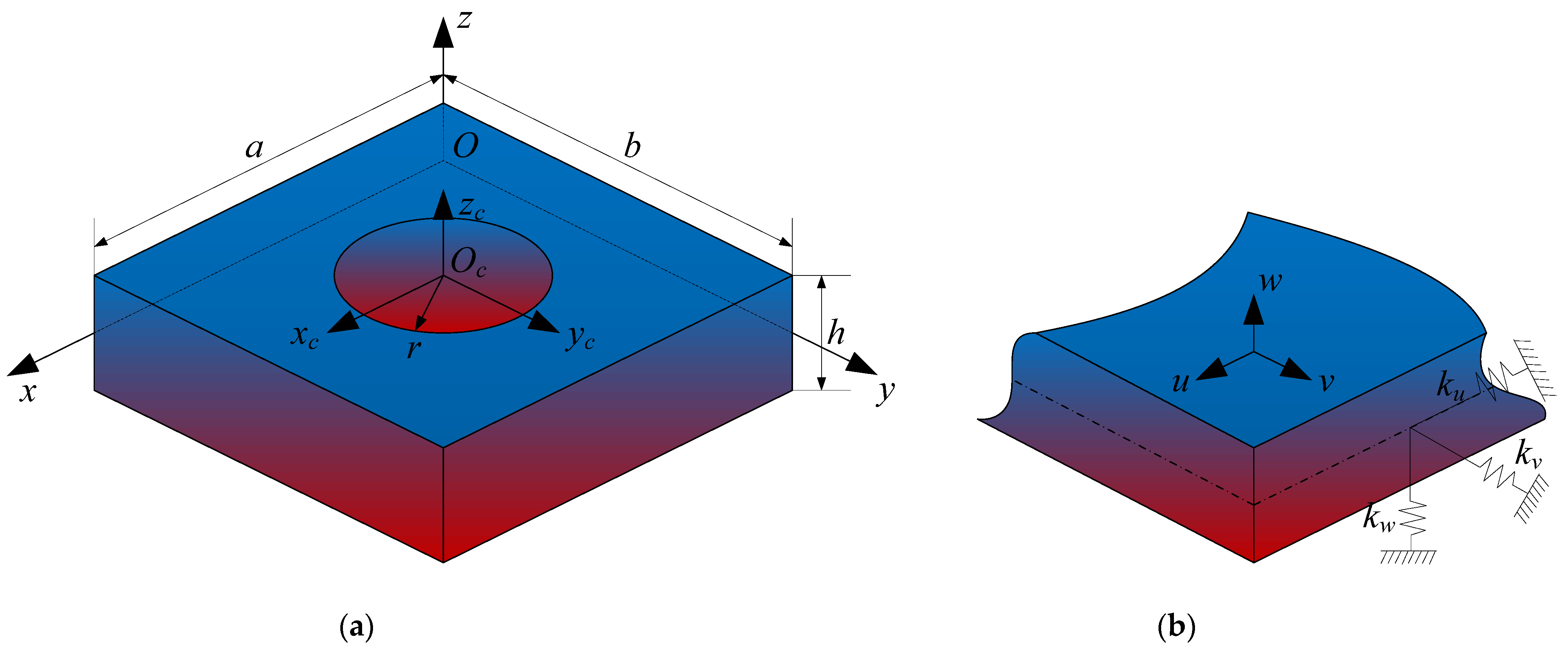
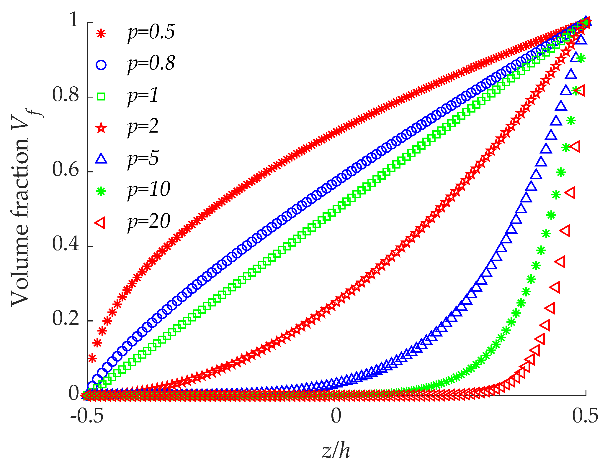
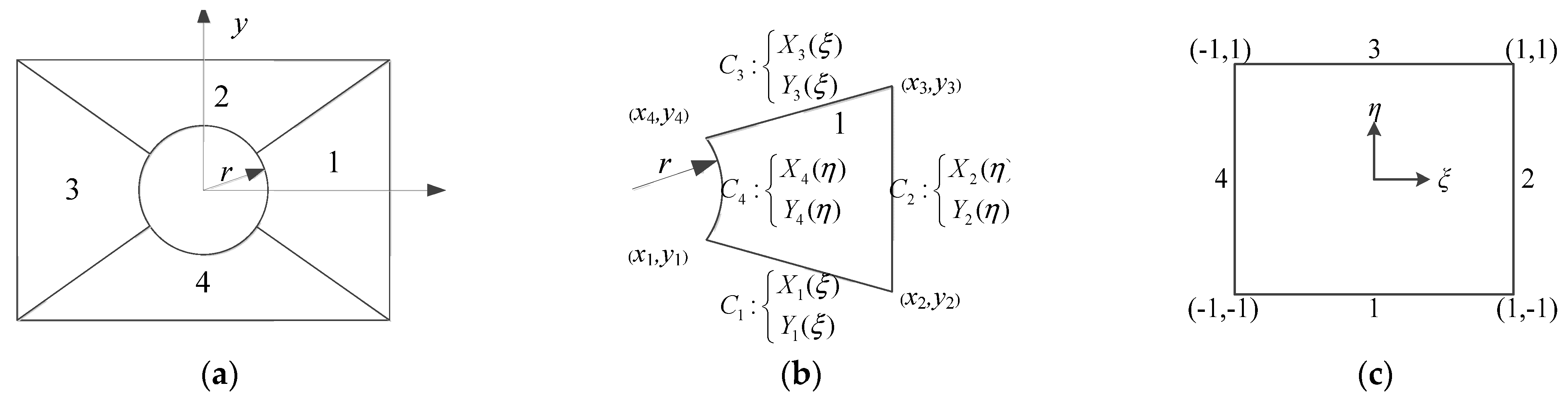
Concerning the above review of literature, it can be noticed that there are only a few papers available on the study of vibration analysis of FGMs plates with cutouts, and in the existing research, the main type of cutout is circular cutout. In addition, there is no report which investigated the vibration solution of FGMs rectangular plate with cutouts based on the three-dimensional elasticity theory. The novelty of the present paper lies in the attempt to establish a unified theoretical analysis model of the vibration characteristics of the FGMs rectangular plate with/without cutouts, and provide the three-dimensional exact solution with general boundary conditions. The material properties of FGMs plates are supposed to vary continuously along the thickness direction in power-law distributions in terms of volume fraction. The highlight of the proposed approach is that the p-version method and the blending function method are employed to discretize the domain and map the closed region to the computational space. All displacements of the FGMs plates are expanded in the form of standard cosine Fourier series plus auxiliary cosine series terms which can improve the convergence speed and reduce the computational complexity. The three-dimensional elasticity theory is combined with Rayleigh–Ritz method to solve the vibration problem of FGMs plate with cutouts. Numerical examples have been studied to verify the convergence, efficiency, and accuracy of the method and the predicted results have been compared with the theoretical solutions. The effects of cutout ratios, cutout positions, and cutout numbers on the natural frequencies are further explored by a parametric study in detail.

2. Theoretical Formulations

2.1. Description of the Problem

In this paper, a FGMs rectangular plate with circular cutout composed of two isotropic materials is considered. Figure 1a presents the three-dimensional geometric model of the structure. In order to describe geometric model clearly, the two coordinate systems are established independently on the mid-plane of the structure, the Cartesian coordinate system (O-xyz) for the rectangular plate region which is located in the corner of the plate, and the cylindrical coordinate system (Oc-xcyczc) for the cutout region which is located in the center of the circular cutout. The x-coordinate is taken along the length of the plate and y- and z-coordinates are taken along the width and thickness directions. The length, width, and thickness of the plate are denoted by the symbols a, b, and h, respectively, and the radius of the cutout is denoted by r. The symbols u, v, and w denote the displacement components in the x, y, and z directions, respectively.
For the FGMs composed of two types of isotropic components, such as ceramics and metals, according to the Voigt mixing rule, the equivalent materials properties can be expressed as
E e f f ( z ) = ( E c E m ) V f + E m
μ e f f ( z ) = ( μ c μ m ) V f + μ m
ρ e f f ( z ) = ( ρ c ρ m ) V f + ρ m
where E is Young’s modulus, μ is Poisson’s ratio, and ρ is density, the subscripts c and m represents the ceramic and metal material, Vf is the volume fraction.
The volume fraction, thus the variation of the material properties of each component can be obtained by assuming to be different function distributions, such as power-law functions (P-FGM), exponential functions (E-FGM), or sigmoid functions (S-FGM) [35]. In this paper, the FGMs with power-law scheme is selected as the research object.
The volume fraction Vf can be defined as
V f = ( 1 2 + z h ) p , h 2 z h 2
where z is the thickness coordinate, and p is gradient index and takes only positive values. When p = 0, the FGMs degenerates into ceramic material and when p = ∞ indicates a fully metal material. Figure 2 shows the curve of volume fraction variation along the thickness direction corresponding to the different gradient index. The volume fraction can be effectively controlled by changing the value of p, and different kinds of FGMs can be designed by changing the above parameters according to different functional requirements.
In this paper, the FGMs plate is considered to be made of aluminum (Al) and alumina (Al2O3), the material properties for ceramic and metallic constituents of FGMs plate are listed in Table 1.

2.2. Kinematic Equations

The strain–displacement relations of the structure can be obtained as follows based on the linear, small-strain three-dimensional elasticity theory
ε x = u x
ε y = v y
ε z = w z
γ y z = w y + v z
γ x z = u z + w x
γ x y = u y + v x
where εx, εy, εz, γyz, γxz, and γxy are the normal and shear strain.
According to the theory of three-dimensional constraint of a linear elasticity, the corresponding stress–strain relations of the three-dimensional structure are written as
[ σ x σ y σ z τ y z τ x z τ x y ] = [ C 11 ¯ ( z ) C 12 ¯ ( z ) C 13 ¯ ( z ) 0 0 C 16 ¯ ( z ) C 12 ¯ ( z ) C 22 ¯ ( z ) C 23 ¯ ( z ) 0 0 C 26 ¯ ( z ) C 13 ¯ ( z ) C 23 ¯ ( z ) C 33 ¯ ( z ) 0 0 C 36 ¯ ( z ) 0 0 0 C 44 ¯ ( z ) C 45 ¯ ( z ) 0 0 0 0 C 45 ¯ ( z ) C 55 ¯ ( z ) 0 C 16 ¯ ( z ) C 26 ¯ ( z ) C 36 ¯ ( z ) 0 0 C 66 ¯ ( z ) ] [ ε x ε y ε z γ y z γ x z γ x y ]
where Cij(z) (i, j = 1, 2,…, 6) are material elastic constants, for isotropic materials, they can be defined as
C 11 ¯ ( z ) = C 22 ¯ ( z ) = C 33 ¯ ( z ) = E e f f ( z ) ( 1 μ e f f ( z ) ) ( 1 + μ e f f ( z ) ) ( 1 2 μ e f f ( z ) )
C 12 ¯ ( z ) = C 13 ¯ ( z ) = C 23 ¯ ( z ) = E e f f ( z ) μ e f f ( z ) ( 1 + μ e f f ( z ) ) ( 1 2 μ e f f ( z ) )
C 44 ¯ ( z ) = C 55 ¯ ( z ) = C 66 ¯ ( z ) = E e f f ( z ) 2 ( 1 + μ e f f ( z ) )
C 16 ¯ ( z ) = C 26 ¯ ( z ) = C 36 ¯ ( z ) = C 45 ¯ ( z ) = 0

2.3. Boundary Conditions

As illustrated in Figure 1b, three groups of boundary springs are factitiously distributed along the edges to simulate different boundary conditions. The symbols ku, kv, and kw are used to indicate the stiffness of the springs, and through adopting appropriate values of the boundary spring stiffness, the classical boundary conditions and elastic boundary conditions can be achieved. The general boundary conditions mainly include free (F), simply supported (S), clamped (C). The expressions of the different boundary conditions along the edge x = 0 are given as follows.
Free boundary condition:
σ x = τ x z = τ x y = 0
Simply supported boundary condition:
σ x = v = w = 0
Clamped boundary condition:
u = v = w = 0
Elastic restraint boundary condition:
u v w 0

2.4. Energy Equations

In the light of Hamilton’s principle, the governing equation of the structure and the boundary conditions are derived in the following work. In this paper, the plate domain and the cutout domain are separated, and the energy functions of the FGMs plate and the cutouts are established independently. The kinetic energy function of the FGMs plate and cutouts can be expressed as
T = 1 2 V [ ( u t ) 2 + ( v t ) 2 + ( w t ) 2 ] d V
The total linear elastic strain energy function is depicted as
U = 1 2 V [ σ x ε x + σ y ε y + σ z ε z + τ y z γ y z + τ x z γ x z + τ x y γ x y ] d V = 1 2 V { Q 11 ( z ) [ ( u x ) 2 + ( v y ) 2 + ( w z ) 2 ] + 2 Q 12 ( z ) [ u x v y + u x w z + v y w z ] + Q 22 ( z ) [ ( w y + v z ) 2 + ( u z + w x ) 2 + ( u y + v x ) 2 ] } d V
The potential energy stored in the boundary springs is expressed as
V = 1 2 y z { [ k x 0 u u 2 + k x 0 v v 2 + k x 0 w w 2 ] x = 0 + [ k x a u u 2 + k x a v v 2 + k x a w w 2 ] x = a } d y d z + 1 2 x z { [ k y 0 u u 2 + k y 0 v v 2 + k y 0 w w 2 ] y = 0 + [ k y b u u 2 + k y b v v 2 + k y b w w 2 ] y = b } d x d z

2.5. Region Mapping

As described in the above model, the coordinate system of the plate is Cartesian coordinate system, and the coordinate system of the cutout is cylindrical coordinate system. The expression of the displacement components is different for the plate and cutout domain, which leads to the complexity of the energy integration. In order to simplify the solution process, a unified coordinate system is needed. The main purpose of this paper to deal with the vibration of rectangular plate with circular cutout is region mapping. The p-version of the finite element method is applied to discretize the plate with cutout into four curve quadrilateral sub-domains as presented in Figure 3a. The length and width of the rectangular plate are a and b, and the radius of the circular cutout is r, respectively. The sub-domain 1 is regarded as a closed region composed of four curves in the x-y coordinate system. The purpose of region mapping is to map the closed quadrilateral region into a unit square region, as described in Figure 3b,c.
The closed quadrilateral region consists of four curves, and the curve sides are in the parametric form: C 1 : X 1 ( ξ ) , Y 1 ( ξ ) , C 2 : X 2 ( η ) , Y 2 ( η ) , C 3 : X 3 ( ξ ) , Y 3 ( ξ ) , C 4 : X 4 ( η ) , Y 4 ( η ) , where 1 ξ 1 , 1 η 1 ; the four vertex-nodes are x i , y i ( i = 1 , 2 , 3 , 4 ), respectively. The blending function method proposed by Gordon and Hall [36] is well suited for the purpose to map the closed quadrilateral region to the computational space.
The mapping functions are given as
x ( ξ , η ) = ( 1 η 2 ) X 1 ( ξ ) + ( 1 + ξ 2 ) X 2 ( η ) + ( 1 + η 2 ) X 3 ( ξ ) + ( 1 ξ 2 ) X 4 ( η ) [ ( ( 1 ξ ) ( 1 η ) 4 ) x 1 + ( ( 1 ξ ) ( 1 + η ) 4 ) x 2 + ( ( 1 + ξ ) ( 1 + η ) 4 ) x 3 + ( ( 1 + ξ ) ( 1 η ) 4 ) x 4 ]
y ( ξ , η ) = ( 1 η 2 ) Y 1 ( ξ ) + ( 1 + ξ 2 ) Y 2 ( η ) + ( 1 + η 2 ) Y 3 ( ξ ) + ( 1 ξ 2 ) Y 4 ( η ) [ ( ( 1 ξ ) ( 1 η ) 4 ) y 1 + ( ( 1 ξ ) ( 1 + η ) 4 ) y 2 + ( ( 1 + ξ ) ( 1 + η ) 4 ) y 3 + ( ( 1 + ξ ) ( 1 η ) 4 ) y 4 ]
Substituting the circular equations and the three linear equations into Equations (23) and (24), the following results can be obtained by
x ( ξ , η ) = 1 4 X 1 ( ξ ) + X 2 ( η ) ( ξ η 4 η 4 ) + X 3 ( ξ ) ( 1 4 + η 4 + ξ 4 + ξ η 4 ) + r cos ( π η 4 ) 2 ξ r cos ( π η 4 ) 2
y ( ξ , η ) = ( 1 η 2 ) Y 1 ( ξ ) + ( 1 + ξ 2 ) Y 2 ( η ) + ( 1 + η 2 ) Y 3 ( ξ ) + ( 1 ξ 2 ) Y 4 ( η ) [ ( ( 1 ξ ) ( 1 η ) 4 ) y 1 + ( ( 1 ξ ) ( 1 + η ) 4 ) y 2 + ( ( 1 + ξ ) ( 1 + η ) 4 ) y 3 + ( ( 1 + ξ ) ( 1 η ) 4 ) y 4 ]
In the light of above region mapping and coordinate transformation relationship, the displacement components of transformation matrix from the global coordinate system to the local coordinate system are related by
{ Ω ( x , y , z ) x Ω ( x , y , z ) y Ω ( x , y , z ) z } = J { Ω ( ξ , η , γ ) ξ Ω ( ξ , η , γ ) η Ω ( ξ , η , γ ) γ }
where J is the Jacobian transformation matrix, and the mathematical expression of Jacobian matrix is
J = [ J 1 , 1 J 1 , 2 J 1 , 3 J 2 , 1 J 2 , 2 J 2 , 3 J 3 , 1 J 3 , 2 J 3 , 3 ] = [ x ( ξ , η , γ ) ξ y ( ξ , η , γ ) ξ z ( ξ , η , γ ) ξ x ( ξ , η , γ ) η y ( ξ , η , γ ) η z ( ξ , η , γ ) η x ( ξ , η , γ ) γ y ( ξ , η , γ ) γ z ( ξ , η , γ ) γ ]
The inverse of the Jacobian transformation matrix is
J 1 = 1 | J | J *
| J | = J 1 , 1 J 2 , 2 J 3 , 3 + J 1 , 2 J 2 , 3 J 3 , 1 + J 1 , 3 J 2 , 1 J 3 , 2 J 1 , 1 J 2 , 3 J 3 , 2 J 1 , 2 J 2 , 1 J 3 , 3 J 1 , 3 J 2 , 2 J 3 , 1
J * = [ J 2 , 2 J 3 , 3 J 2 , 3 J 3 , 2 J 2 , 3 J 3 , 1 J 2 , 1 J 3 , 3 J 2 , 1 J 3 , 2 J 2 , 2 J 3 , 1 J 1 , 3 J 3 , 2 J 1 , 2 J 3 , 3 J 1 , 1 J 3 , 3 J 1 , 3 J 3 , 1 J 1 , 2 J 3 , 1 J 1 , 1 J 3 , 2 J 1 , 2 J 2 , 3 J 1 , 3 J 2 , 2 J 1 , 3 J 2 , 1 J 1 , 1 J 2 , 3 J 1 , 1 J 2 , 2 J 1 , 2 J 2 , 1 ]

2.6. Solution Procedure

In this paper, the Rayleigh–Ritz method is used due to it is applicable to arbitrary boundary conditions without requiring any special procedures. Thus, it is very important to construct an admissible displacement function field because the accuracy and the convergence of the solution depend on the accuracy of the expression of the admissible displacement function. In this paper, the improved Fourier series method is further extended to the three-dimensional vibration analysis of FGMs rectangular plate with cutouts. According to the author’s previous research, the admissible displacement functions are consistent with [37], and expressed in the form of complete trigonometric Fourier series, thus the auxiliary terms are also in the form of trigonometric Fourier series. The three-dimensional admissible displacement functions of the FGMs plate are expressed as three variables separated along the x, y, and z directions as
U ( x , y , z ) = m = 0 M n = 0 N q = 0 Q A m n q cos λ m x cos λ n y cos λ q z + m = 0 M n = 0 N [ a u _ z ξ 1 c ( z ) + b u _ z ξ 2 c ( z ) ] cos λ m x cos λ n y   + m = 0 M q = 0 Q [ a u _ y ξ 1 b ( y ) + b u _ y ξ 2 b ( y ) ] cos λ m x cos λ q z + n = 0 N q = 0 Q [ a u _ x ξ 1 a ( x ) + b u _ x ξ 2 a ( x ) ] cos λ n y cos λ q z
V ( x , y , z ) = m = 0 M n = 0 N q = 0 Q B m n q cos λ m x cos λ n y cos λ q z + m = 0 M n = 0 N [ a v _ z ξ 1 c ( z ) + b v _ z ξ 2 c ( z ) ] cos λ m x cos λ n y   + m = 0 M q = 0 Q [ a v _ y ξ 1 b ( y ) + b v _ y ξ 2 b ( y ) ] cos λ m x cos λ q z + n = 0 N q = 0 Q [ a v _ x ξ 1 a ( x ) + b v _ x ξ 2 a ( x ) ] cos λ n y cos λ q z
W ( x , y , z ) = m = 0 M n = 0 N q = 0 Q C m n q cos λ m x cos λ n y cos λ q z + m = 0 M n = 0 N [ a w _ z ξ 1 c ( z ) + b w _ z ξ 2 c ( z ) ] cos λ m x cos λ n y   + m = 0 M q = 0 Q [ a w _ y ξ 1 b ( y ) + b w _ y ξ 2 b ( y ) ] cos λ m x cos λ q z + n = 0 N q = 0 Q [ a w _ x ξ 1 a ( x ) + b w _ x ξ 2 a ( x ) ] cos λ n y cos λ q z
where λ m = m π / a , λ n = n π / b , λ q = q π / h , and A m n q , B m n q , C m n q , a u , a v , a w , b u , b v , b w are the unknown Fourier coefficients, M, N, and Q are the truncation numbers with respect to variables x, y, and z directions, respectively. In order to unify the form of the admissible displacement functions and simplify the mathematical processing, the supplementary functions are defined as
ξ 1 a ( x ) = 1 2 [ sin ( 2 π x / a ) + sin ( π x / a ) ]
ξ 2 a ( x ) = 1 2 [ cos ( 3 π x / 2 a ) cos ( π x / 2 a ) ]
ξ 1 b ( y ) = 1 2 [ sin ( 2 π y / b ) + sin ( π y / b ) ]
ξ 2 b ( y ) = 1 2 [ cos ( 3 π y / 2 b ) cos ( π y / 2 b ) ]
ξ 1 c ( z ) = 1 2 [ sin ( 2 π z / h ) + sin ( π z / h ) ]
ξ 2 c ( z ) = 1 2 [ cos ( 3 π z / 2 h ) cos ( π z / 2 h ) ]
The total energy of the FGMs rectangular plate with circular cutout is defined by subtracting the energy of cutout domain part from the entire plate domain. Thus, the Lagrangian energy function of the structure can be expressed as
= p i = 1 n i
The subscripts “p” and “i” denote the energy of the plate and cutout domains, respectively.
For the plate without cutout, the energy equation is
= T p U p V p
Substituting Equations (20)–(22), (27), and (32)–(34) and into Equation (41), and by minimizing the Lagrangian energy functional with respect to each unknown coefficients to be zero, we can get the equation
X = 0 ( X = A m n q , B m n q , C m n q , a u , a v , a w , b u , b v , b w )
The standard eigenvalue equation of motion for rectangular plate with circular cutout can be expressed in the form of matrix
[ ( K p i = 1 n K i ) ω 2 ( M p i = 1 n M i ) ] X = ( K ω 2 M ) X = 0
where K , M , and X are the stiffness matrices, mass matrices and the unknown Fourier coefficients matrices, respectively. All of the natural frequencies and mode shapes of the three-dimensional FGMs rectangular plates with circular cutouts can be obtained by solving Equation (44).

3. Results and Discussion

In this section, according to the unified theoretical analysis model established above, several examples for the three-dimensional vibration analysis of FGMs plate with/without cutouts are presented to illustrate the accuracy and reliability of the proposed method. Firstly, a suitable spring stiffness value is investigated, and then the convergence, efficiency and validation are checked. Secondly, the vibration modal experiment of an aluminum square plate with a center circular cutout is conducted to verify the correctness of the proposed method. Finally, a parametric study of the FGMs plate with cutouts is carried out from free vibration characteristics and harmonic response analysis, including the cutout sizes, cutout positions, and cutout numbers.
For simplicity, the boundary conditions of the structure are described in the form of character combination, unless other stated, the non-dimensional frequency parameter is expressed as: Ω = ω a 2 ρ c h / D c , where D c is the flexural stiffness of Alumina, D c = E c h 3 / 12 ( 1 μ 2 ) .

3.1. Determination of the Spring Stiffness

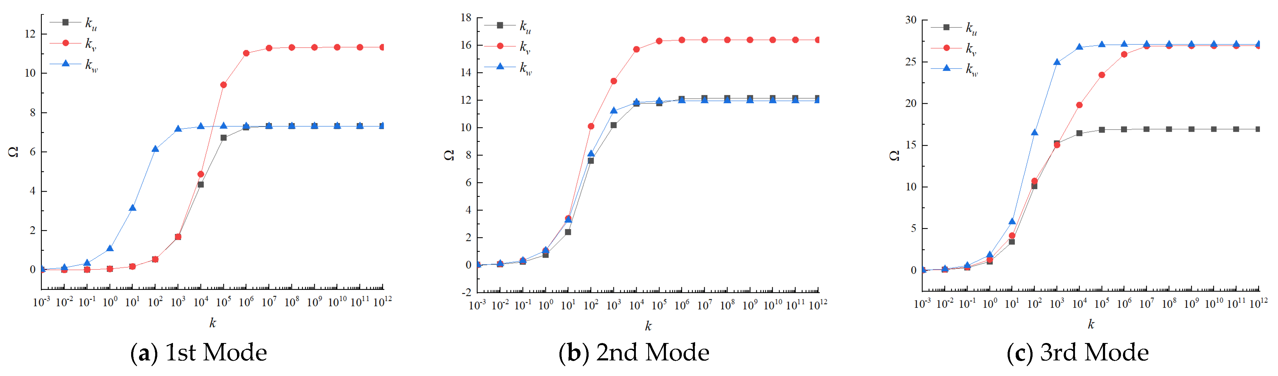
In this paper, three groups of linear springs are introduced to simulate different kinds of boundary conditions by changing the values of spring stiffness. The accuracy of the solutions is strongly affected by the selection of appropriate spring stiffness values. Therefore, in this section, the FGMs square plate without cutout is taken as an example to study the determination of the spring stiffness. The variations of the first three non-dimensional frequency parameters of FGMs square plate versus different spring stiffness are given in Figure 4. The geometric dimensions and the material parameters are as follows: a = b = 1   m , h = 0.05   m , and p = 1 . The boundary conditions of the plate are defined as: the edge y = 0 and y = b are completely free and the x = 0 and x = a are elastic supported by one group of spring constrain varying from 10−3Dc to 1012Dc. From Figure 4, it can be seen that the non-dimension frequency parameters are unchanged and approaches 0 when the spring stiffness is smaller than 10−1Dc, and when the spring stiffness is varied from 10−1Dc to 107Dc, the frequency parameters increase rapidly. Finally, when the spring stiffness exceeds 107Dc, the frequency parameters will approach their utmost and tend to be stable. Therefore, we can arrive at the conclusion that the free boundary conditions and clamped boundary conditions can be simulated by assigning the spring stiffness value to be 0 or 107Dc.

3.2. Convergence of the Method

Convergence property for the free vibration analysis of FGMs plate with circular cutout is examined in terms of the limited number of terms in the displacement expressions in actual calculation to verify the accuracy and efficiency of the proposed method. Table 2 shows the convergence studies of the first six non-dimensional frequency parameters of a FGMs square plate with a central circular cutout with different truncated numbers, and the data of [38] are also given out in Table 2. The truncated number of admissible displacement function components in Fourier series expansion is expressed as M × N × Q, and the truncated number of this paper is from 3 to 10. It can be observed that the maximum error with [38] is 1.7898%, and the main reason of the error is that the first order shear theory is adopted by [38]. It can be concluded that the proposed method has fast convergence and good stability, and the truncation numbers will be set as M = N = Q = 10 in the following studies.

3.3. Validity of the Method

3.3.1. Numerical Examples Study

In this section, in order to verify the proposed method is also suitable for solving the vibration characteristics of FGMs plate without cutouts, the comparison study of a FGMs square plate under SSSS boundary condition will be carried out by the present method and other method presented in [25]. Table 3 shows the first eight non-dimensional frequency parameters of FGMs square plate which was studied by Huang et al. The values of the gradient indexes are taken to be 0, 1, 2, 5, 10. The symbol ‘-’ indicates that the frequencies were not considered in the reference work. In the table, the thickness–length ratio is taken as 0.1 and 0.2, it is moderate–thick plate structure. From the comparison, we can see a consistent agreement of the results taken from the current method and the referential data. From the tables, it is obvious that these data show a similar behavior, that is the frequency parameters decrease with the increase of gradient index. When the thickness–length ratio is 0.1, the gradient index increases from 0 to 10, the first-order non-dimensional frequency parameter decreases by 36.95%, and when the thickness–length ratio is 0.1, the first-order non-dimensional frequency parameter decline rate is 38.44%. The main reason is that the increase of gradient index leads to the decrease of the volume fraction of the corresponding ceramic components, which reduces the stiffness of the structure, and finally leads to the decrease of frequency. In addition, the increase of thickness–length ratios leads to decrease of the frequency parameters for all of the cases considered. By way of illustration, as the thickness–length ratio increases, the first-order non-dimensional frequency parameter drops by 8.19% when the gradient index is 0. According to the relationship between the non-dimensional frequency parameters calculation formula and thickness, it can be known that the natural frequencies increase with the increase of thickness. The increase of thickness will increase the stiffness and mass of rectangular plate, but the increase of stiffness plays a decisive role in the influence of natural frequency.
For the next comparison study, a FGMs rectangular plate with a central circular cutout under CCCC-F boundary condition is examined. In Table 4, the first fix non-dimensional frequency parameters are obtained. It is observed that the frequencies are in excellent agreement with those given in [38], which verifies the accuracy and efficiency of the proposed model. The effect of gradient index on the frequency parameters of structure with cutout is consistent with that structure without cutout also can be concluded from the table below. Therefore, the effect of material parameters on structure with cutout is independent of the geometric size of the structure. In addition, it can be seen that the frequency parameters show an increasing trend with the increase of the structural aspect ratio, but it is not a linear trend. Take the gradient index is 0 as an example, when the aspect ratio is 1.5, the first-order non-dimensional frequency parameter is 1.67 times that when the aspect ratio is 1, while it is 2.7 times when the aspect ratio is 2. This is mainly because when the aspect ratio increases, the overall mass and stiffness of the structure will also increase, and the stiffness is the main factor affecting frequency parameters.
Numerous results of the first six non-dimensional frequency parameters are demonstrated in Table 5 for the FGMs square plate with central circular cutout under different boundary conditions. The square plate with boundary restrains, including SSSS-F, SCSC-F, SFSF-F, FCFC-F, FFCF-F, FCCC-F, FSCS-F, and FCCF-F are considered. From the table below, the influence of boundary conditions on the frequency parameters is obvious, the stronger the boundary restrains, the higher the corresponding frequency parameters, this can be clearly confirmed from SFSF-F, SSSS-F, and SCSC-F boundary conditions. Comparing three groups of boundary conditions—FCFC-F, FCCF-F, and FCCC-F—it can be concluded that the clamped boundary constrain plays an important role in the frequency parameters, while frequency parameter of the opposite side constraint is larger than that of the adjacent side constraint.
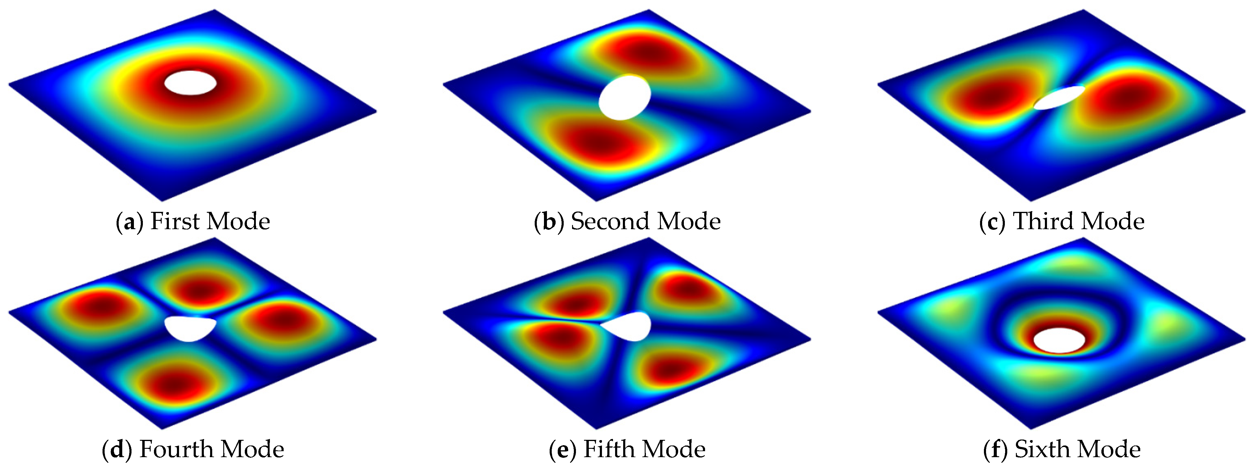
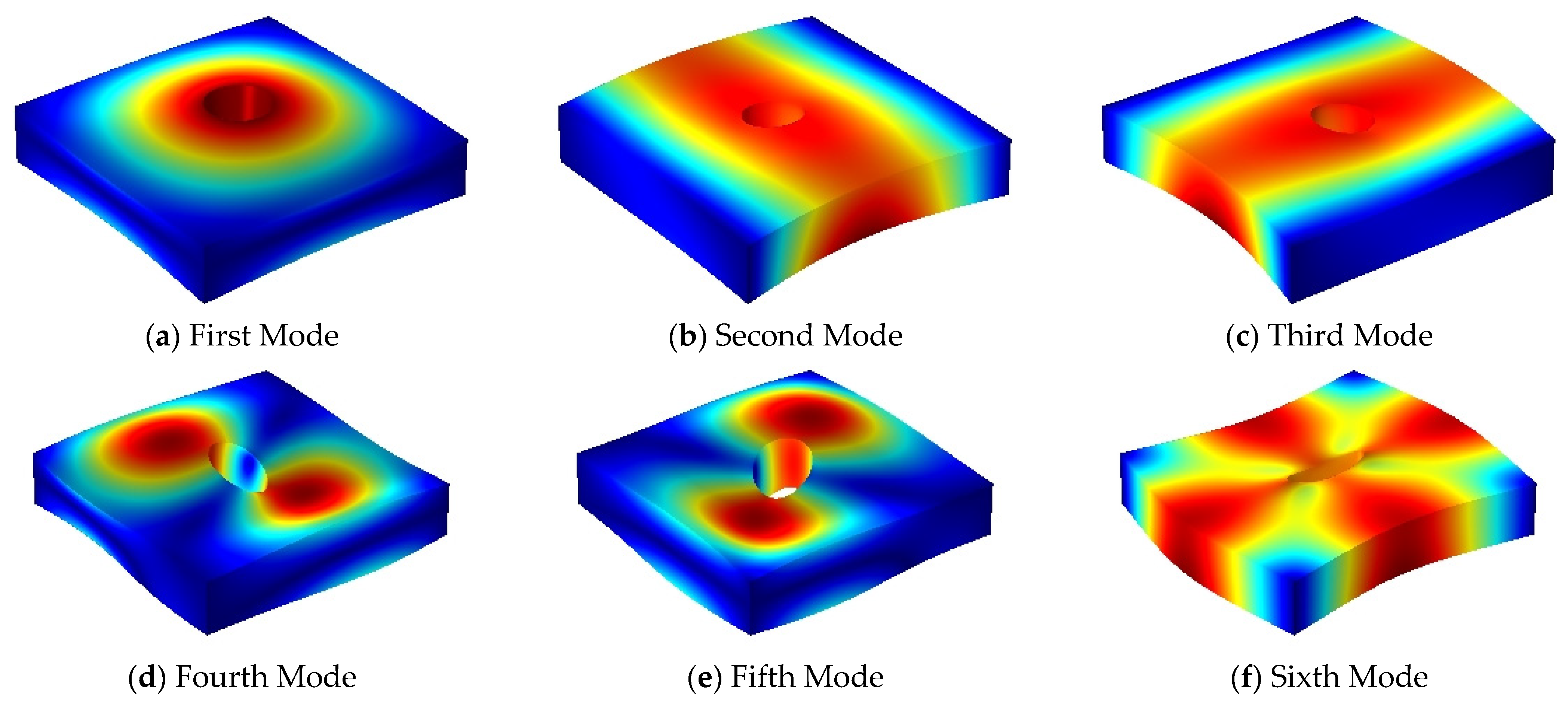
The first six mode shapes of the FGMs square plate with central circular cutout under SSSS-F boundary condition when the thickness–length ratio is 0.01 and 0.2 are presented in Figure 5 and Figure 6, respectively. From the graphs below, for thin plate structure, the lower order mode shapes are mainly transverse vibration, while for moderate thick plate structure, the shear deformation along the thickness direction gradually appears. The three dimensions of the elastic plate structure have complex deformation forms for different modes, therefore the analysis based on the three-dimensional elastic theory can fully consider the influence of the shear deformation in the thickness direction on the vibration characteristics of the structure.

3.3.2. Experimental Study

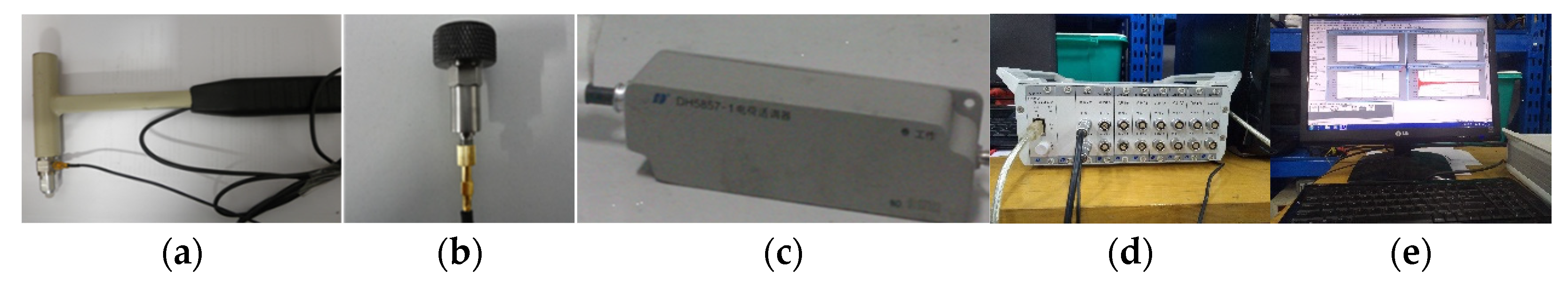
In this part, an experimental study of plate with central cutout is conducted to further verify the validity of the proposed method. The experimental setup—including the hammer, accelerometer sensor, charge adapter, dynamic data acquisition instrument, and computer—is shown in 
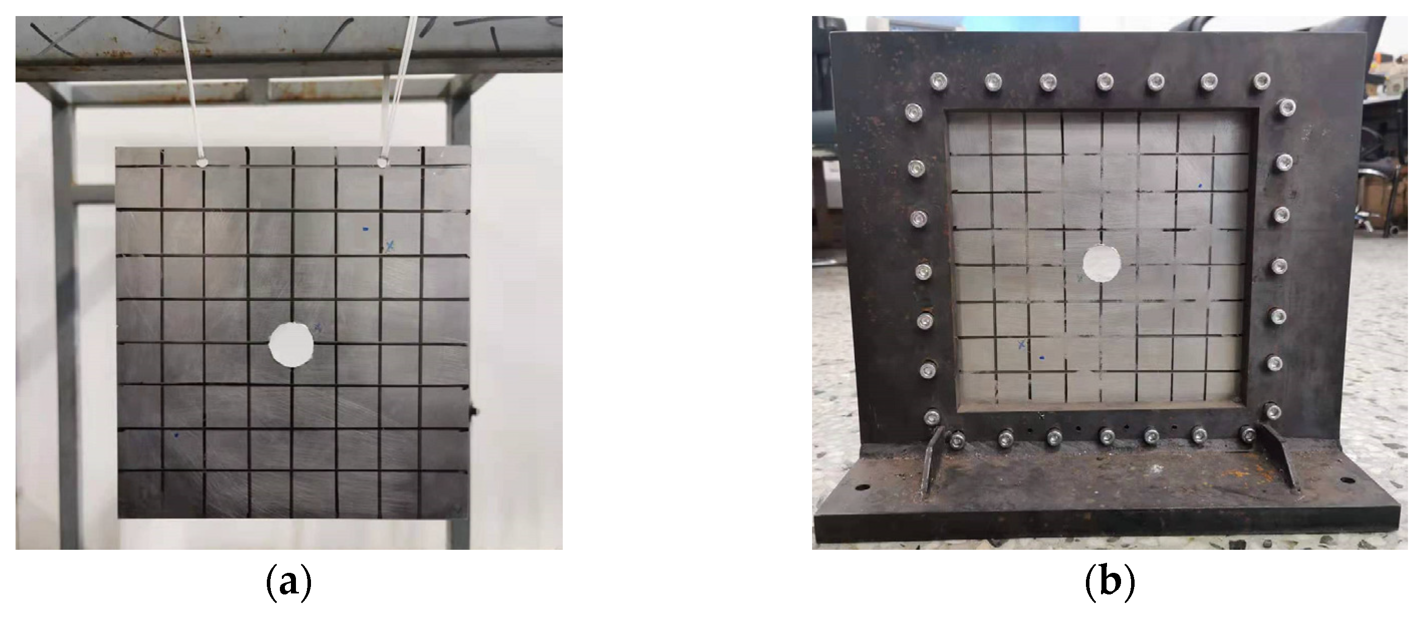
Figure 7. In view of the available situation, the gradient index is considered to be infinity, thus the functionally graded material degenerates to be completely aluminum. A square plate with central circular cutout under FFFF-F and CCCC-F boundary condition are examined. It is impossible to realize the complete free boundary condition in the actual experimental environment, two small holes are opened on the edge of the structure, and elastic rubber ropes are used to hang the structure on the frame, as shown in Figure 8a. For the CCCC-F boundary condition, the experimental model adopts two thicker L-shaped plates and arranges bolts uniformly around the rectangular plate structure to simulate the fixed boundary condition, as shown in Figure 8b. The parameters of dimension and the material of the structure are given in Table 6. Table 7 shows the first six natural frequencies of the structure obtained by the present method and the experiment. Through the comparative analysis of experiments and the calculation of the proposed method, the difference is 4.754% for the worst case, which is acceptable. The main reason for the error lies in two aspects. Firstly, the difference of boundary restrains between the experimental simulation and the theoretical calculation will cause a certain error. Secondly, when knocking with a hammer, it requires that the knocking direction is completely perpendicular to the panel surface, the knocking force should be constant, and the hammer shall be evacuated quickly when the knocking is finished to avoid secondary knocking, which is difficult to ensure in the process of experiment. The experimental frequency values are obtained from the vibration analysis software by searching the peak within a certain range of the frequency, and three are some interference items near desired the frequency value, the peak value is automatically identified and selected by the computer, this is also the reason for the error. The experimental values are smaller than the theoretical value, the main reason is due to the additional mass of the accelerometer which is attached to the panel.

3.4. Parametric Study

In this section, the parametric study of three-dimensional vibration characteristics of the FGMs plate with cutouts is carried out. Based on the existing literature, the structural vibration characteristics of different functionally graded material parameters are different, and the predecessors have done a lot of research on this. This section emphasizes the study of the influence of the parameters of the cutout on the free vibration characteristics and harmonic response analysis of the structure, including the cutout sizes, cutout positions, and number of the cutout. The FGMs square plate with circular cutouts under CCCC-F boundary conditions is taken as the analysis object, and the geometric parameters and materials parameters are set as follows: a = b = 1   m , h = 0.1   m , p = 1 .
First, the variation of the non-dimensional frequency parameters with respect to diverse cutout sizes is investigated. Table 8 presents the first six frequency parameters of the FGMs square plate with a central circular cutout, and the cutout size ratios (r/a) vary from 0 to 0.25. For the small values of cutout size ratio, the frequency parameters of the structure with and without cutout are almost the same. It is found that the change trend of the low-order modal frequency parameters of the structure is relatively simple, a minimum value for the first five modes exists and the frequency parameters first decrease and then increase when the cutout ratio rise, while the change of the high-order frequency parameters is more complicated. The reason may be due to the weight of mass loss and stiffness loss on the frequency parameters is different with the increase of cutout size ratio.
Then, the harmonic analysis is used to analyze the steady-state response of the FGMs plate with cutouts under simple harmonic excitation. In order to overcome the problem of numerical instability caused by structural resonance at the modal frequency of the external excitation, the damping factor will be introduced in the form of complex Young’s modulus, thus E ¯ = E ( 1 + j η ) , η = 0.01 . Assuming that a simple harmonic force is applied to point A along the z-axis, and the magnitude of the force is 1 N. The coordinates of the excitation force application point A and the selected response observation point B are (0.5 m, 0.8 m, 0.05 m) and (0.8 m, 0.8 m, 0.05 m), respectively. Figure 9a,b provide the results obtained from the preliminary analysis of the displacement response curve of the excitation force application point and the response observation point with frequency in the range of 0–5000 Hz. The range of the cutout size ratio is from 0 to 0.25 with a step of 0.025, and the displacement response is H = 20 * log ( w ) . From the graph below we can see that there has been a slight rise in the displacement response with the gradual increase of the cutout size rate. This is mainly because the stiffness of the excitation force application point and the observation point is weakened by the introduction of the cutout. The resonance peak of the displacement response will shift left and right with the increase of cutout size ratio. To further explain, in Figure 9a, the first-order resonance peak frequency is 1225 Hz when the structure is without cutout, the first-order resonance peak frequency is 1221 Hz when the cutout ratio is 0.05, and the first-order resonance peak frequency is 1246 Hz when the cutout ratio is 0.1, in the case of a larger cutout ratio, it can be clearly seen that the first-order resonance peak frequency is increasing, which is consistent with the change trend of the data in Table 8.
The following part of the study is concerned with the position of the cutout. The radius of the cutout is 0.1 m, and the position of cutout varies along the x-axis. The table below illustrates the first six non-dimensional frequency parameters of the FGMs square plate with different cutout positions. In Table 9, when the cutout position x c = 0.5 , it means that the cutout is located in the center of rectangular plate. The table reveals that as the cutout position gradually approaches the edge of the structure, the fundamental frequency parameter of the structure gradually declines, the second order frequency parameters of the structure gradually increases, while the higher order frequency parameters changes are more complicated.
The results of the correlational analysis of displacement response for FGMs square plate with different cutout positions are shown in Figure 10. From the graph below we can see that in the frequency range of 0–3000 Hz, the vibration displacement response at the resonance peak changes slightly, for the excitation force application point, the amplitudes of the first-order resonance peaks are −378.658 dB, −378.957 dB, −379.589 dB, and −379.962 dB, respectively. While the excitation frequency is greater than 3000 Hz, the vibration displacement response at the resonance peak changes obviously.
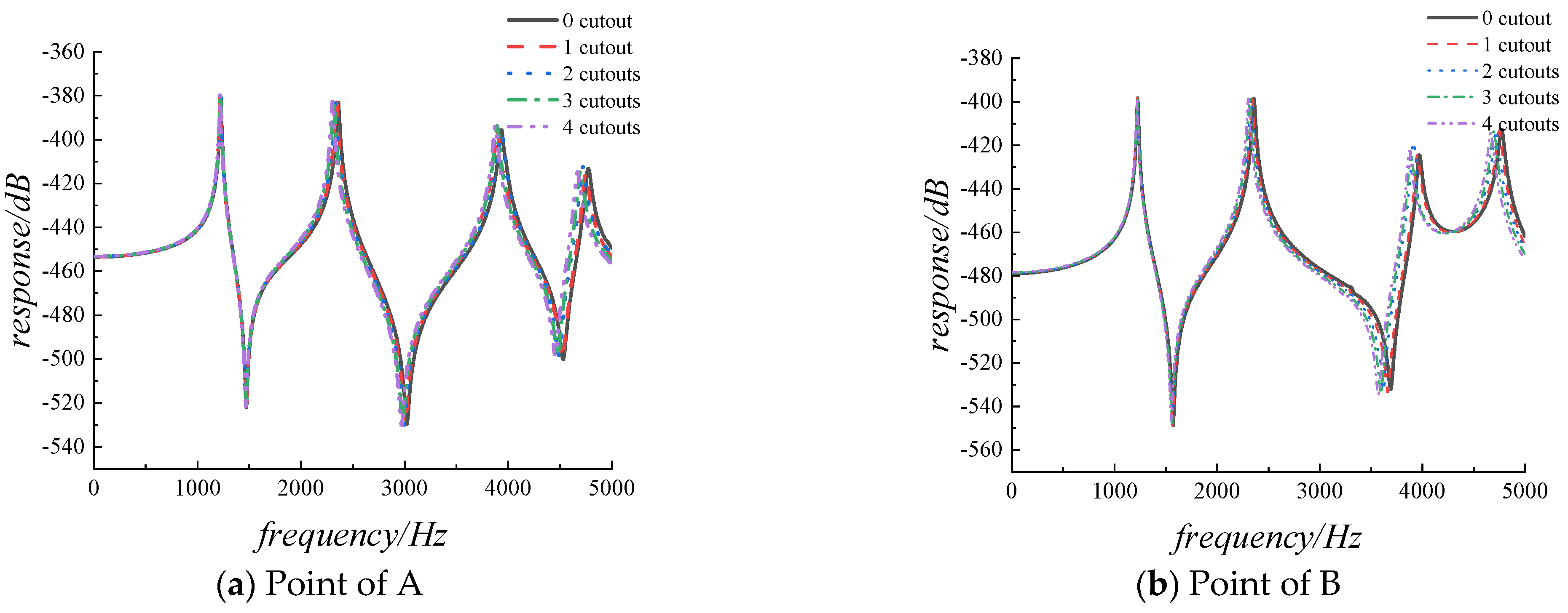
In actual engineering structures, it is often necessary to evenly arrange multiple cutouts on the structure, so in the final part of the study, the influence of the number of cutout on the vibration characteristics of the structure is investigated. Table 9 provides the first six non-dimensional frequency parameters of the FGMs square plate with different cutout numbers, the cutouts are evenly distributed along the x-axis direction. The radius of the cutouts is 0.05 m, and the other parameters remain the same with the previous data. What can be clearly seen in Table 10 is the decrease with the increasing in the number of cutouts for the frequency parameters of all orders. The results of the harmonic response correlational analysis of are presented in Figure 11. The graph shows that there has been a small change for the amplitude of the displacement response with the increasing of the cutout numbers, while all resonance peaks gradually shift to the left.

4. Conclusions

The aim of the present research is to establish a unified three-dimensional solution to deal with the vibration characteristics of FGMs plate with/without circular cutouts. The material properties vary continuously along the thickness direction according to the power-law distribution. The artificial spring technology is used to simulate the general boundary conditions by setting three groups of linear springs and assigning them with appropriate spring stiffness values. Due to relatively complicated governing differential equations and domain of the problem, the p-version of the finite element method is applied to discretize the plate with cutout into four curve quadrilateral sub-domains, and then map the closed quadrilateral region to the computational space by the blending function method. The independent coordinate coupling relationship is used to derive the Jacobian relationship matrix of the rectangular plate domain and the circular cutout domain, finally the Lagrangian energy equation is used to solve the differential equation. In the analysis of numerical examples, it is found that the calculation results of this method are in good agreement with other results through comparison with the existing literature and finite element simulation analysis results, which verifies that the method proposed in this paper is reliable. Then the effects of cutout sizes, cutout positions, and cutout numbers on the frequency parameters of FGMs plate with cutout are studied and discussed, and all of these factors will have an impact on the frequency parameters. The proposed method can be applicable to solve the vibration of complex shape plate with cutouts, and the numerical results can be useful for future research.

Author Contributions

Conceptualization, W.H., K.X., and Q.L.; Methodology, W.H. and Q.L.; Programming, W.H.; Validation, W.H., K.X., and Q.L.; Writing—original draft preparation, W.H.; Writing—review and editing, W.H., K.X., and Q.L.; Visualization, W.H.; Supervision, K.X. and Q.L.; Project administration, W.H., K.X., and Q.L.; Funding acquisition, Q.L. All authors have read and agreed to the published version of the manuscript.

Funding

This research was funded by the National Natural Science Foundation of China (no. 51405096) and the Fundamental Research Funds for the Central Universities (HEU3072021CF0710).

Institutional Review Board Statement

Not applicable.

Informed Consent Statement

Not applicable.

Data Availability Statement

The data presented in this study are available on request from the corresponding author.

Conflicts of Interest

The authors declare no conflict of interest.

References

  1. Khandan, R.; Noroozi, S.; Sewell, P.; Vinney, J. The development of laminated composite plate theories: A review. J. Mater. Sci. 2012, 47, 5901–5910. [Google Scholar] [CrossRef]
  2. Liew, K.; Pan, Z.; Zhang, L. An overview of layerwise theories for composite laminates and structures: Development, numerical implementation and application. Compos. Struct. 2019, 216, 240–259. [Google Scholar] [CrossRef]
  3. Ekici, R.; Apalak, M.K.; Yildirim, M. Indentation behavior of functionally graded Al–SiC metal matrix composites with random particle dispersion. Compos. Part B Eng. 2011, 42, 1497–1507. [Google Scholar] [CrossRef]
  4. Chi, S.H.; Chung, Y.L. Mechanical behavior of functionally graded material plates under transverse load—Part I: Analysis. Int. J. Solids Struct. 2006, 43, 3657–3674. [Google Scholar] [CrossRef] [Green Version]
  5. Chi, S.H.; Chung, Y.L. Mechanical behavior of functionally graded material plates under transverse load—Part II: Numerical results. Int. J. Solids Struct. 2006, 43, 3675–3691. [Google Scholar] [CrossRef] [Green Version]
  6. Abrate, S. Functionally graded plates behave like homogeneous plates. Compos. Part B Eng. 2008, 39, 151–158. [Google Scholar] [CrossRef]
  7. Zhang, D.G.; Zhou, Y.H. A theoretical analysis of FGMs thin plates based on physical neutral surface. Comput. Mater. Sci. 2008, 44, 716–720. [Google Scholar] [CrossRef]
  8. Zhao, X.; Lee, Y.; Liew, K.M. Free vibration analysis of functionally graded plates using the element-free kp-Ritz method. J. Sound Vibr. 2009, 319, 918–939. [Google Scholar] [CrossRef]
  9. Hosseini-Hashemi, S.; Taher, H.R.D.; Akhavan, H.; Omidi, M. Free vibration of functionally graded rectangular plates using first-order shear deformation plate theory. Appl. Math. Model. 2010, 34, 1276–1291. [Google Scholar] [CrossRef]
  10. Hosseini-Hashemi, S.; Fadaee, M.; Atashipour, S.R. A new exact analytical approach for free vibration of Reissner–Mindlin functionally graded rectangular plates. Int. J. Mech. Sci. 2011, 53, 11–22. [Google Scholar] [CrossRef]
  11. Qu, Y.; Long, X.; Yuan, G.; Meng, G. A unified formulation for vibration analysis of functionally graded shells of revolution with arbitrary boundary conditions. Compos. Part B Eng. 2013, 50, 381–402. [Google Scholar] [CrossRef]
  12. Ferreira, A.; Batra, R.; Roque, C.; Qian, L.; Jorge, R. Natural frequencies of functionally graded plates by a meshless method. Compos. Struct. 2006, 75, 593–600. [Google Scholar] [CrossRef]
  13. Thai, H.T.; Choi, D.H. A simple first-order shear deformation theory for the bending and free vibration analysis of functionally graded plates. Compos. Struct. 2013, 101, 332–340. [Google Scholar] [CrossRef]
  14. Fallah, A.; Aghdam, M.; Kargarnovin, M. Free vibration analysis of moderately thick functionally graded plates on elastic foundation using the extended Kantorovich method. Arch. Appl. Mech. 2013, 83, 177–191. [Google Scholar] [CrossRef]
  15. Neves, A.; Ferreira, A.; Carrera, E.; Cinefra, M.; Roque, C.; Jorge, R.; Soares, C. Free vibration analysis of functionally graded shells by a higher-order shear deformation theory and radial basis functions collocation, accounting for through-the-thickness deformations. Eur. J. Mech. A-Solids. 2013, 37, 24–34. [Google Scholar] [CrossRef] [Green Version]
  16. Phung-Van, P.; Abdel-Wahab, M.; Liew, K.; Bordas, S.; Nguyen-Xuan, H. Isogeometric analysis of functionally graded carbon nanotube-reinforced composite plates using higher-order shear deformation theory. Compos. Struct. 2015, 123, 137–149. [Google Scholar] [CrossRef]
  17. Thanh, C.L.; Phung-Van, P.; Thai, C.H.; Nguyen-Xuan, H.; Wahab, M.A. Isogeometric analysis of functionally graded carbon nanotube reinforced composite nanoplates using modified couple stress theory. Compos. Struct. 2018, 184, 633–649. [Google Scholar] [CrossRef]
  18. Dozio, L. Exact free vibration analysis of Lévy FGM plates with higher-order shear and normal deformation theories. Compos. Struct. 2014, 111, 415–425. [Google Scholar] [CrossRef]
  19. Jodaei, A.; Jalal, M.; Yas, M. Free vibration analysis of functionally graded annular plates by state-space based differential quadrature method and comparative modeling by ANN. Compos. Part B Eng. 2012, 43, 340–353. [Google Scholar] [CrossRef]
  20. Nie, G.; Zhong, Z. Semi-analytical solution for three-dimensional vibration of functionally graded circular plates. Comput. Meth. Appl. Mech. Eng. 2007, 196, 4901–4910. [Google Scholar] [CrossRef]
  21. Malekzadeh, P. Three-dimensional free vibration analysis of thick functionally graded plates on elastic foundations. Compos. Struct. 2009, 89, 367–373. [Google Scholar] [CrossRef]
  22. Dong, C. Three-dimensional free vibration analysis of functionally graded annular plates using the Chebyshev–Ritz method. Mater. Des. 2008, 29, 1518–1525. [Google Scholar] [CrossRef]
  23. Zhou, D.; Au, F.; Cheung, Y.; Lo, S. Three-dimensional vibration analysis of circular and annular plates via the Chebyshev–Ritz method. Int. J. Solids Struct. 2003, 40, 3089–3105. [Google Scholar] [CrossRef]
  24. Zhou, D.; Lo, S.; Au, F.; Cheung, Y.; Liu, W. 3-D vibration analysis of skew thick plates using Chebyshev–Ritz method. Int. J. Mech. Sci. 2006, 48, 1481–1493. [Google Scholar] [CrossRef]
  25. Huang, C.S.; McGee, O.G., III; Wang, K. Three-dimensional vibrations of cracked rectangular parallelepipeds of functionally graded material. Int. J. Mech. Sci. 2013, 70, 1–25. [Google Scholar] [CrossRef]
  26. Jin, G.; Su, Z.; Shi, S.; Ye, T.; Gao, S. Three-dimensional exact solution for the free vibration of arbitrarily thick functionally graded rectangular plates with general boundary conditions. Compos. Struct. 2014, 108, 565–577. [Google Scholar] [CrossRef]
  27. Zhao, J.; Choe, K.; Xie, F.; Wang, A.; Shuai, C.; Wang, Q. Three-dimensional exact solution for vibration analysis of thick functionally graded porous (FGP) rectangular plates with arbitrary boundary conditions. Compos. Part B Eng. 2018, 155, 369–381. [Google Scholar] [CrossRef]
  28. Van Do, V.N.; Lee, C.H. Free vibration analysis of FGM plates with complex cutouts by using quasi-3D isogeometric approach. Int. J. Mech. Sci. 2019, 159, 213–233. [Google Scholar]
  29. Bansal, G.; Gupta, A.; Katiyar, V. Vibration of porous functionally graded plates with geometric discontinuities and partial supports. Proc. Inst. Mech. Eng. Part C-J. Eng. Mech. Eng. Sci. 2020, 234, 4149–4170. [Google Scholar] [CrossRef]
  30. Asemi, K.; Ashrafi, H.; Shariyat, M. Three-dimensional stress and free vibration analyses of functionally graded plates with circular holes by the use of the graded finite element method. J. Appl. Mech. Tech. Phys. 2016, 57, 690–700. [Google Scholar] [CrossRef]
  31. Rahimabadi, A.A.; Natarajan, S.; Bordas, S.P. Vibration of functionally graded material plates with cutouts & cracks in thermal environment. Key Eng. Mater. 2013, 560, 157–180. [Google Scholar]
  32. Enab, T.A. Stress concentration analysis in functionally graded plates with elliptic holes under biaxial loadings. Ain Shams Eng. J. 2014, 5, 839–850. [Google Scholar] [CrossRef] [Green Version]
  33. Janghorban, M.; Zare, A. Thermal effect on free vibration analysis of functionally graded arbitrary straight-sided plates with different cutouts. Lat. Am. J. Solids Struct. 2011, 8, 245–257. [Google Scholar] [CrossRef] [Green Version]
  34. Zhao, X.; Lee, Y.; Liew, K.M. Mechanical and thermal buckling analysis of functionally graded plates. Compos. Struct. 2009, 90, 161–171. [Google Scholar] [CrossRef]
  35. Gupta, A.; Talha, M. Recent development in modeling and analysis of functionally graded materials and structures. Prog. Aeosp. Sci. 2015, 79, 1–14. [Google Scholar] [CrossRef]
  36. Gordon, W.J.; Hall, C.A. Transfinite element methods: Blending-function interpolation over arbitrary curved element domains. Numer. Math. 1973, 21, 109–129. [Google Scholar] [CrossRef]
  37. Xue, K.; Huang, W.; Li, Q. Three-Dimensional Vibration Analysis of Laminated Composite Rectangular Plate with Cutouts. Materials 2020, 13, 3113. [Google Scholar] [CrossRef]
  38. Zhang, J.; Li, T.; Zhu, X. Free Vibration Analysis of Rectangular Fgm Plates with a Cutout. IOP Conf. Ser. Earth Environ. Sci. 2019, 283, 012037. [Google Scholar] [CrossRef]
Figure 1. Model of a three-dimensional FGMs rectangular plate with a circular cutout: (a) The geometry and coordinates; (b) The boundary restraining springs.
Materials 14 07088 g001
Figure 2. Variation of volume fraction with different gradient index.
Materials 14 07088 g002
Figure 3. Discretization of rectangular plate with circular cutout: (a) geometric region; (b) closed quadrilateral region; (c) calculation region.
Materials 14 07088 g003
Figure 4. Variation of non-dimensional frequency parameters versus different spring stiffness for FGMs rectangular plate.
Materials 14 07088 g004
Figure 5. The first six mode shapes for SSSS-F FGMs square plate with central circular cutout (h/a = 0.01, p = 1).
Materials 14 07088 g005
Figure 6. The first six mode shapes for SSSS-F FGMs square plate with central circular cutout (h/a = 0.2, p = 1).
Materials 14 07088 g006
Figure 7. The experimental setup: (a) hammer; (b) accelerometer sensor; (c) charge adapter; (d) dynamic data acquisition instrument; (e) computer.
Materials 14 07088 g007
Figure 8. The FGMs plate with central circular cutout: (a) FFFF-F boundary condition; (b) CCCC-F boundary condition.
Materials 14 07088 g008
Figure 9. The displacement response for FGMs square plate with diverse cutout sizes.
Materials 14 07088 g009
Figure 10. The displacement response for FGMs square plate with diverse cutout positions.
Materials 14 07088 g010
Figure 11. The displacement response for FGMs square plate with different cutout numbers.
Materials 14 07088 g011
Table 1. Material properties of the FGMs plate.
PropertiesAluminum (Al)Alumina (Al2O3)Unit
E 70380GPa
ρ 27003800Kg/m3
μ 0.30.3
Table 2. Non-dimensional frequency parameters of FGMs square plate with a central circular cutout under FFFF-F boundary condition ( Ω = ω a 2 ρ c h / E c , a = b = 1   m , r = 0.1   m , h = 0.01   m , p = 1 ).
M × N × QModes
123456
3 × 3 × 310.168414.891218.694627.621027.746149.5969
4 × 4 × 410.002314.452417.752026.553326.558846.3665
5 × 5 × 59.982514.418417.639026.467126.468546.0454
6 × 6 × 69.972914.405317.597726.429126.429245.9154
7 × 7 × 79.964014.399317.577226.403226.403645.8507
8 × 8 × 89.958914.396917.571926.391026.391245.8319
9 × 9 × 99.959714.396117.569526.391826.392345.8232
10 × 10 × 109.956414.394417.567026.384626.384945.8131
Ref. [38]9.907014.466017.820026.411026.412046.6480
Error(%)0.49840.49471.41960.10010.10281.7898
Table 3. The first eight non-dimensional frequency parameters of FGMs square plate without cutout under SSSS boundary condition ( Ω = ω a 2 / h ρ c / E c , a = b = 1   m ).
h/apMethodsModes
12345678
0.10Present5.777113.806213.806219.483319.483321.217425.874225.8742
Ref. [25]5.777013.810013.810019.480019.4800---
1Present4.426710.629110.629116.203316.203316.400620.047720.0478
Ref. [25]4.426010.630010.630016.200016.2000---
5Present3.77288.93088.930812.641012.641013.624616.548216.5482
Ref. [25]3.77208.92708.927012.640012.6400---
10Present3.64248.58868.588611.528211.528213.060215.832615.8326
Ref. [25]3.64108.58708.587011.520011.5200---
0.20Present5.30379.74179.741711.645611.645613.776816.882619.4833
Ref. [25]5.30409.74209.742011.650011.6500---
1Present4.09968.08998.08999.10889.108811.418413.312115.8149
Ref. [25]4.09908.08908.08909.10709.1070---
5Present3.40576.29796.29797.34547.34548.864310.549712.4190
Ref. [25]3.40506.29606.29607.34307.3430---
10Present3.26475.75085.75086.97516.97518.10829.952511.3994
Ref. [25]3.26405.74905.74906.97506.9750---
Table 4. The first six non-dimensional frequency parameters of FGMs rectangular plate with central circular cutout under CCCC-F boundary condition ( b = 1   m , r = 0.1   m , h = 0.01   m ).
a/bpMethodsModes
123456
10Present36.535871.435271.4386105.4876127.5262138.6374
Ref. [38]36.420071.190071.1900105.1500127.0900138.1200
0.5Present31.142460.897760.903289.9195108.7118118.1773
Ref. [38]31.200061.080061.080087.5700106.3200116.2600
1Present27.899054.562654.569180.562897.4015105.8843
Ref. [38]28.120055.050055.050078.970095.8300104.7800
2Present25.367349.604149.610373.243088.549596.2584
Ref. [38]25.570050.050050.050071.760087.120095.2600
10Present22.600644.182744.191065.257478.886085.7766
Ref. [38]23.440045.880045.890065.770079.880087.3300
1.50Present61.108592.9936146.0148149.5540177.0082221.1563
Ref. [38]60.970092.7900145.6600149.2100176.5700220.6000
0.5Present52.075979.2583124.4491127.4684150.8639188.5330
Ref. [38]52.180078.3200123.7200126.1200147.0100187.3000
1Present46.660471.0142111.5217114.2040135.1729168.9314
Ref. [38]47.030070.5900111.5100113.6600132.5000168.8900
2Present42.426864.5684101.3901103.8366122.8967153.5787
Ref. [38]42.750064.1800101.3800103.3300120.4500153.5300
10Present38.250258.181091.388293.5478110.7397138.2982
Ref. [38]39.220058.850092.950094.8000110.4300140.6000
20Present98.7524126.9054178.8877250.1018252.4322282.2987
Ref. [38]98.5100126.6400178.5500249.6700251.7700281.5500
0.5Present84.1596108.1565152.4540213.1582215.1543240.6124
Ref. [38]83.9400106.4700151.3800210.3000212.7000234.3100
1Present75.404096.9035136.5945190.9989192.7910215.5763
Ref. [38]75.650095.9500136.4300189.5400191.7000211.1900
2Present68.563088.1106124.1989173.6566175.2810196.0024
Ref. [38]68.770087.2400124.0300172.3300174.2800191.9900
10Present61.797479.4025111.9418156.5118157.9518176.5748
Ref. [38]63.130080.0100113.8000157.9200159.8000176.0800
Table 5. The first six non-dimensional frequency parameters of the FGMs square plate with central circular cutout under different boundary conditions ( a = b = 1   m , r = 0.1   m , h = 0.2   m ).
pModesBC
SSSS-FSCSC-FSFSF-FFCFC-FFFCF-FFCCC-FFSCS-FFCCF-F
1113.317917.91786.721414.05322.540214.86648.71234.7443
227.485727.503210.823515.70975.500922.842212.926114.5219
327.485730.187520.814424.06298.748631.907719.988516.5373
428.727634.512021.950025.094513.391632.455425.235220.8138
528.727644.108123.948731.627916.876037.618626.834926.2324
631.716546.397624.115034.149518.506038.543334.106026.5989
2112.014716.06736.081812.61002.303613.32937.86484.2878
224.746724.78019.757814.05634.955120.397411.673712.9999
324.746727.020318.782921.47077.914028.727817.904914.8286
425.767730.768119.655722.630312.013228.918522.629918.8357
525.767739.650121.490028.187415.153433.692424.213223.4904
628.574241.362921.751830.378816.575934.255630.452723.9566
5111.110614.47565.675211.34252.164111.97207.27733.9791
221.382021.39399.012612.58094.562518.273210.084611.7849
321.382024.028716.228219.36106.844024.831416.241313.4594
423.052826.923217.987819.552310.959625.315420.413616.2938
523.052934.175618.783424.660713.953329.715720.931520.5253
624.664436.262419.419626.650514.996029.996227.123121.2598
10110.671813.74735.466910.75392.088811.34916.98823.8236
219.544719.54918.656411.92494.377317.35869.197111.2591
319.544722.677914.813117.85766.234022.715015.510312.8460
421.819625.227017.149118.490210.491023.736219.114614.8380
521.819731.277617.289123.109613.426427.864419.407418.7537
622.542833.991818.473025.061914.297628.197125.680720.1745
Table 6. Dimensions and material parameters of the structure.
ParameterValueUnitParameterValueUnit
length245mm E 70Gpa
width245mm ρ 2700Kg/m3
thickness5mm μ 0.3
radius15mm
Table 7. The first six natural frequencies of the square plate with a central cutout.
BCMethodsModes
123456
FFFF-FPresent264.661386.901484.493694.383694.4321235.285
Experiment257.680375.950469.310674.490678.2601176.560
Error(%)2.6382.8303.1342.8652.3294.754
CCCC-FPresent732.4481489.3221489.7962179.9022642.3412678.284
Experiment724.3701448.7401453.4202102.8702584.6502608.280
Error(%)1.1032.7252.4423.5342.1832.614
Table 8. The first six non-dimensional frequency parameters of the FGMs square plate with diverse cutout sizes.
Cutout Size Ratio r/aModes
123456
025.501249.101849.109369.224881.983882.7225
0.02525.400148.900548.906068.793881.403982.0926
0.0525.363848.620648.622168.408080.859482.0073
0.07525.479647.939647.945067.946580.220383.0599
0.125.866846.822846.835967.396579.432485.4772
0.12526.623545.513845.516466.708078.364089.1572
0.1527.814744.348744.350665.760176.884993.7810
0.17529.512043.650043.663364.532575.104895.0332
0.231.821343.755343.760963.257673.546294.6269
0.22534.872144.777644.782962.169572.664093.7299
0.2538.820646.907246.915061.634373.045892.8681
Table 9. The first six non-dimensional frequency parameters of the FGMs square plate with diverse cutout positions.
Cutout Position xcModes
123456
0.525.866846.822846.835967.396579.432485.4772
0.5525.837646.869447.162267.304279.104083.9540
0.625.771447.009648.086967.103977.970382.3428
0.6525.658647.215149.202666.892477.240182.1270
0.725.503647.498749.834866.815678.465482.8420
0.7525.294547.817549.577966.987280.195084.1670
0.825.031348.143348.664967.422481.059183.9047
Table 10. The first six non-dimensional frequency parameters of the FGMs square plate with diverse cutout numbers.
Cutout NumbersModes
123456
025.501249.101849.109369.224881.983882.7225
125.363848.620648.622168.408081.459482.0073
225.432248.431248.749768.254081.193281.7552
325.384848.083448.472067.641180.751680.8624
425.312647.814048.390967.171780.396080.4916
Publisher’s Note: MDPI stays neutral with regard to jurisdictional claims in published maps and institutional affiliations.

