
A Simple Method of Reducing Coolant Leakage for Direct Metal Printed Injection Mold with Conformal Cooling Channels Using General Process Parameters and Heat Treatment


Abstract
:1. Introduction
2. Experimental Details
3. Results and Discussion
4. Conclusions
- This study shows great potential for application in the mold industry for its improved fabrication of an injection mold in terms of economics, efficiency, and speed. This simple method is applicable to any direct-metal-printed injection molds that incorporate CCC.
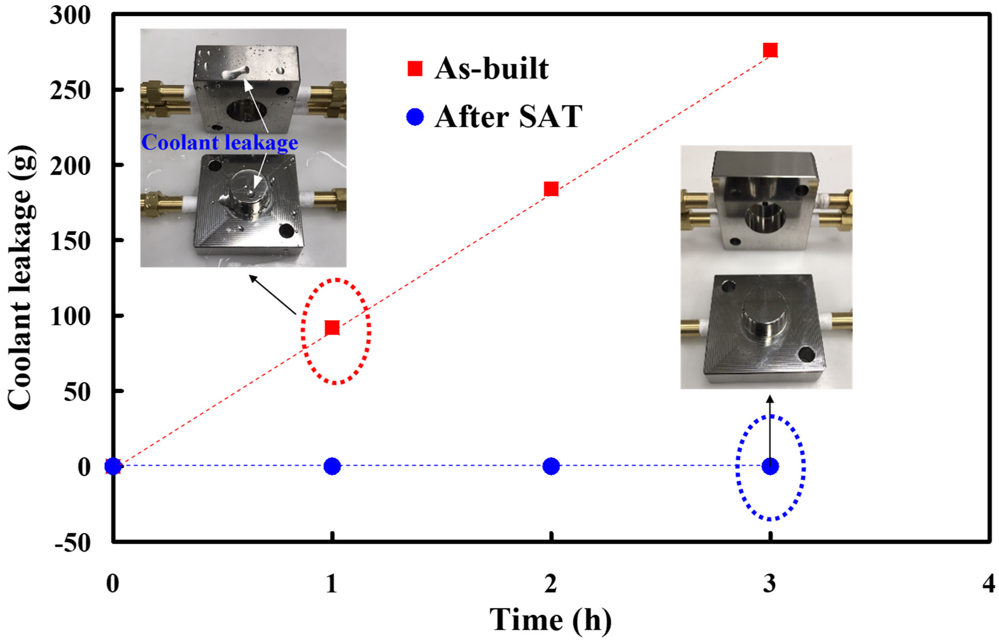
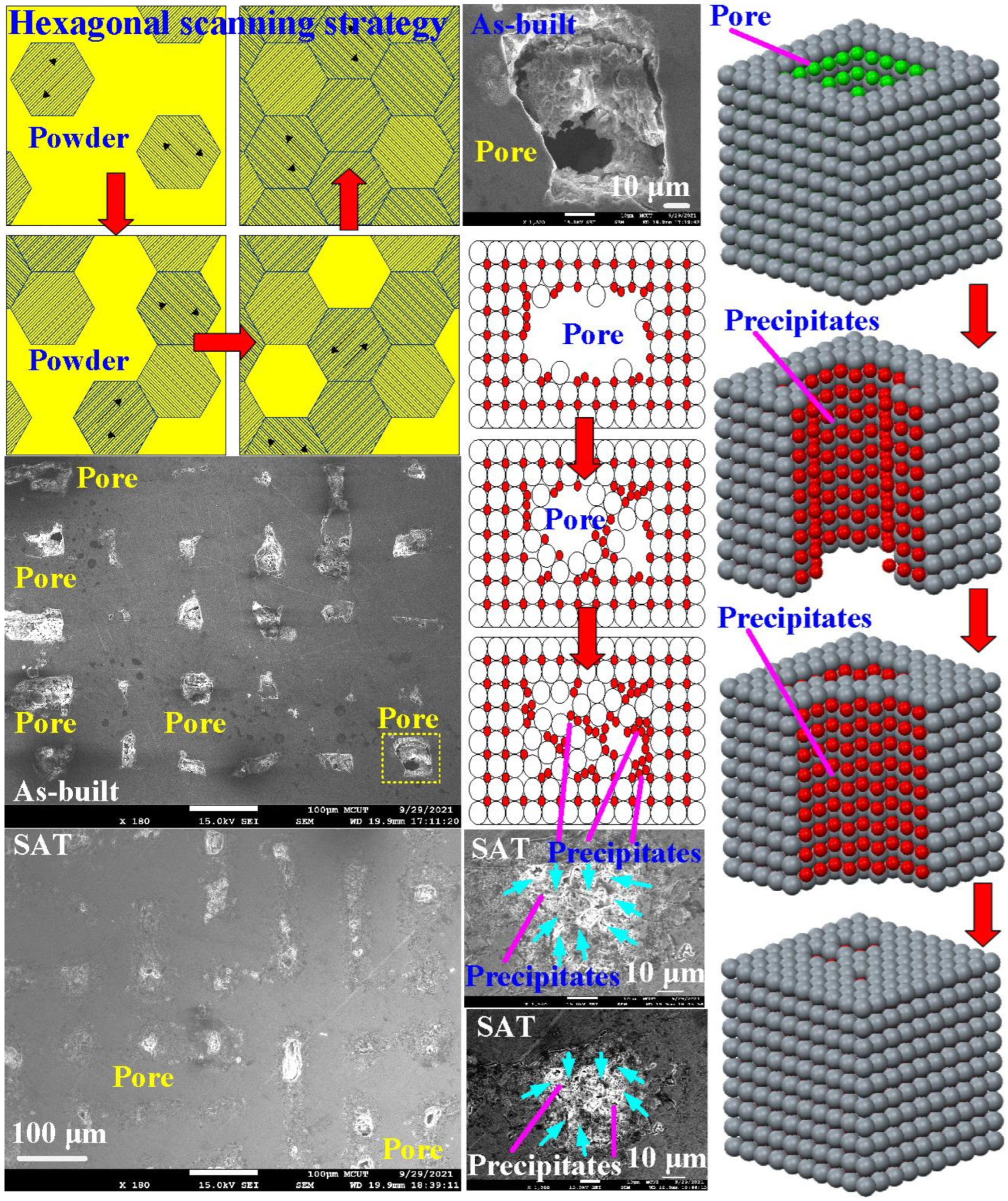
- We comprehensively investigated and described the mechanism of the prevention of coolant leakage in direct-metal-printed injection molds with CCC.
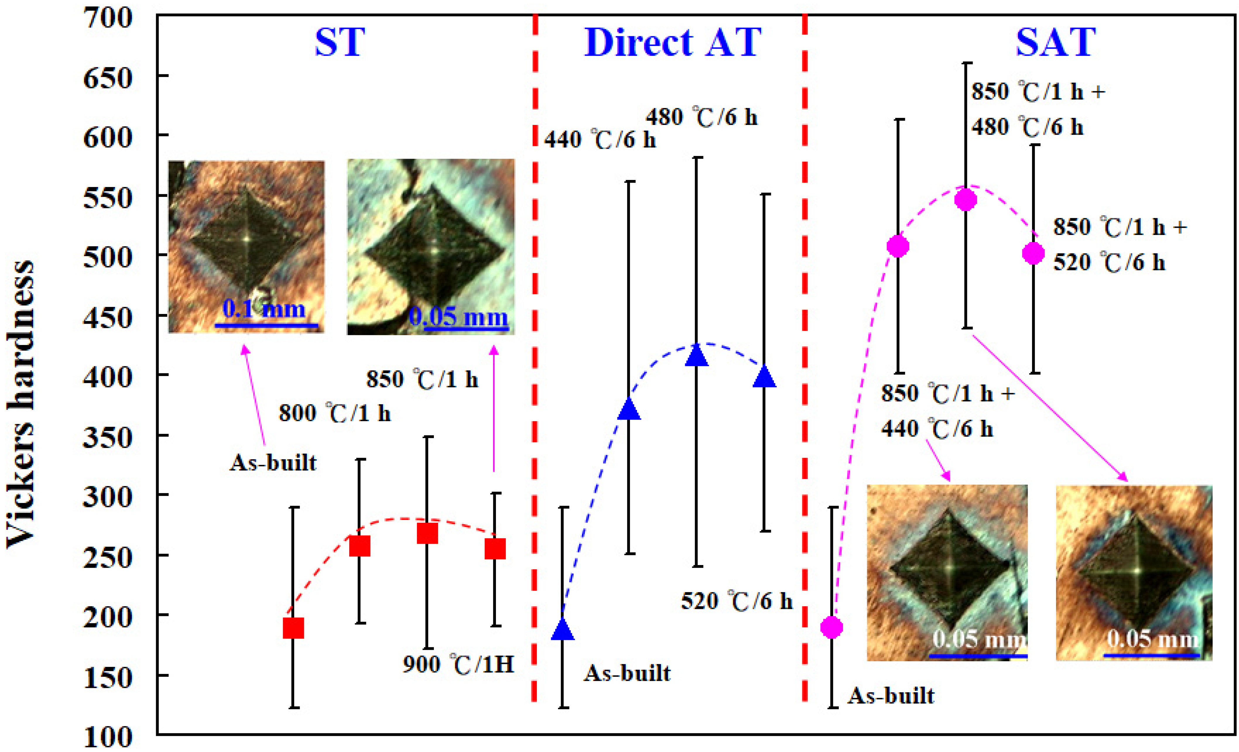
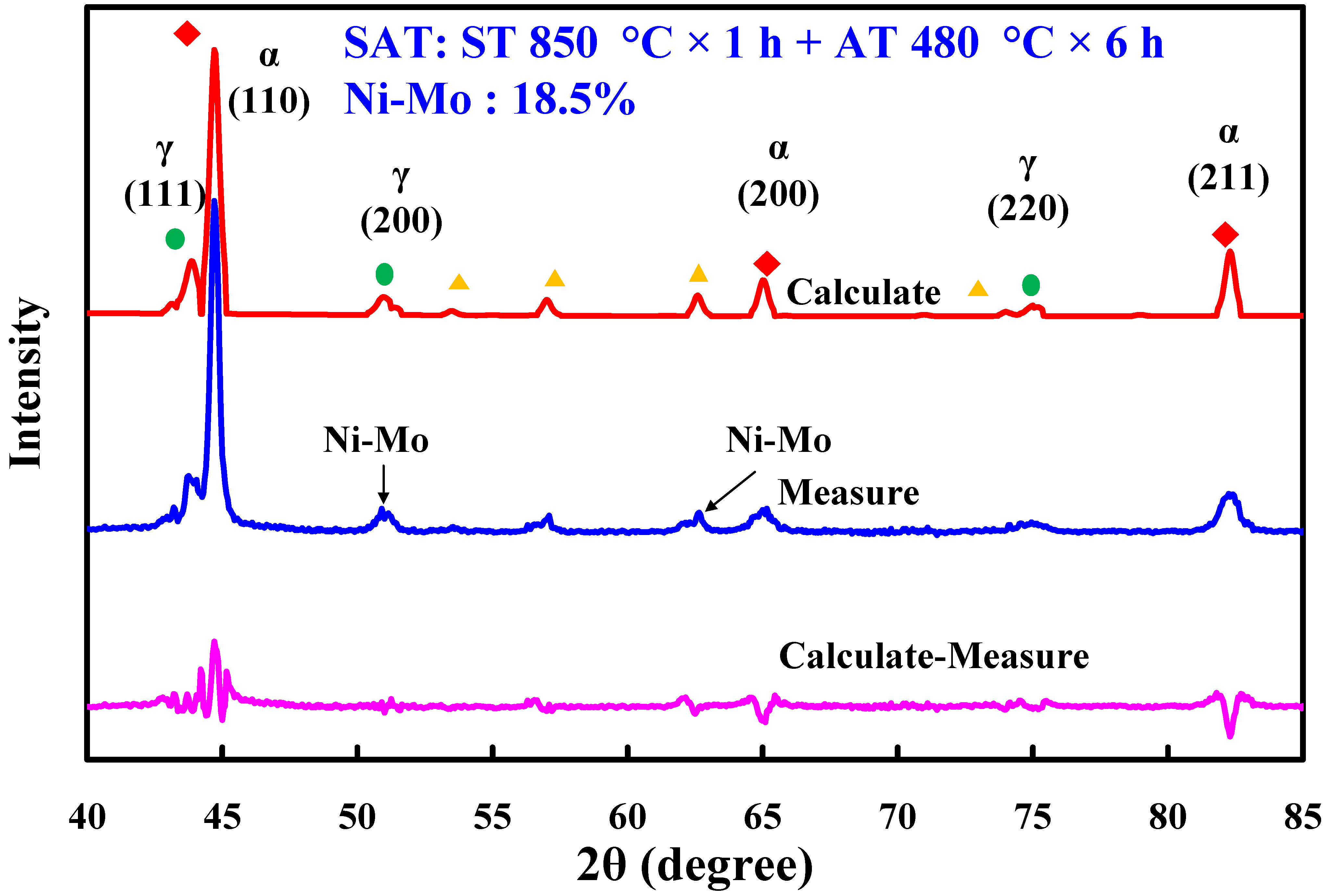
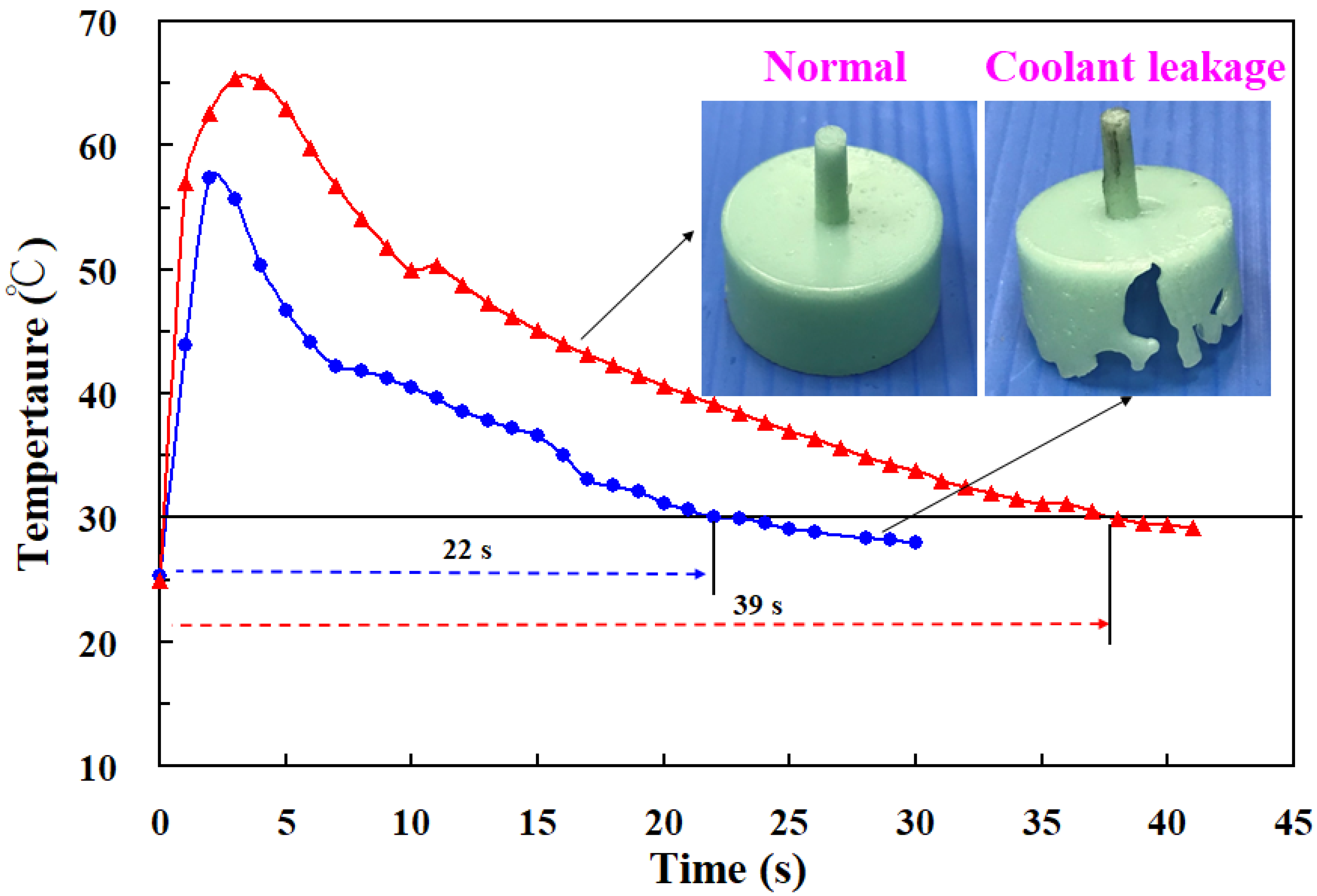
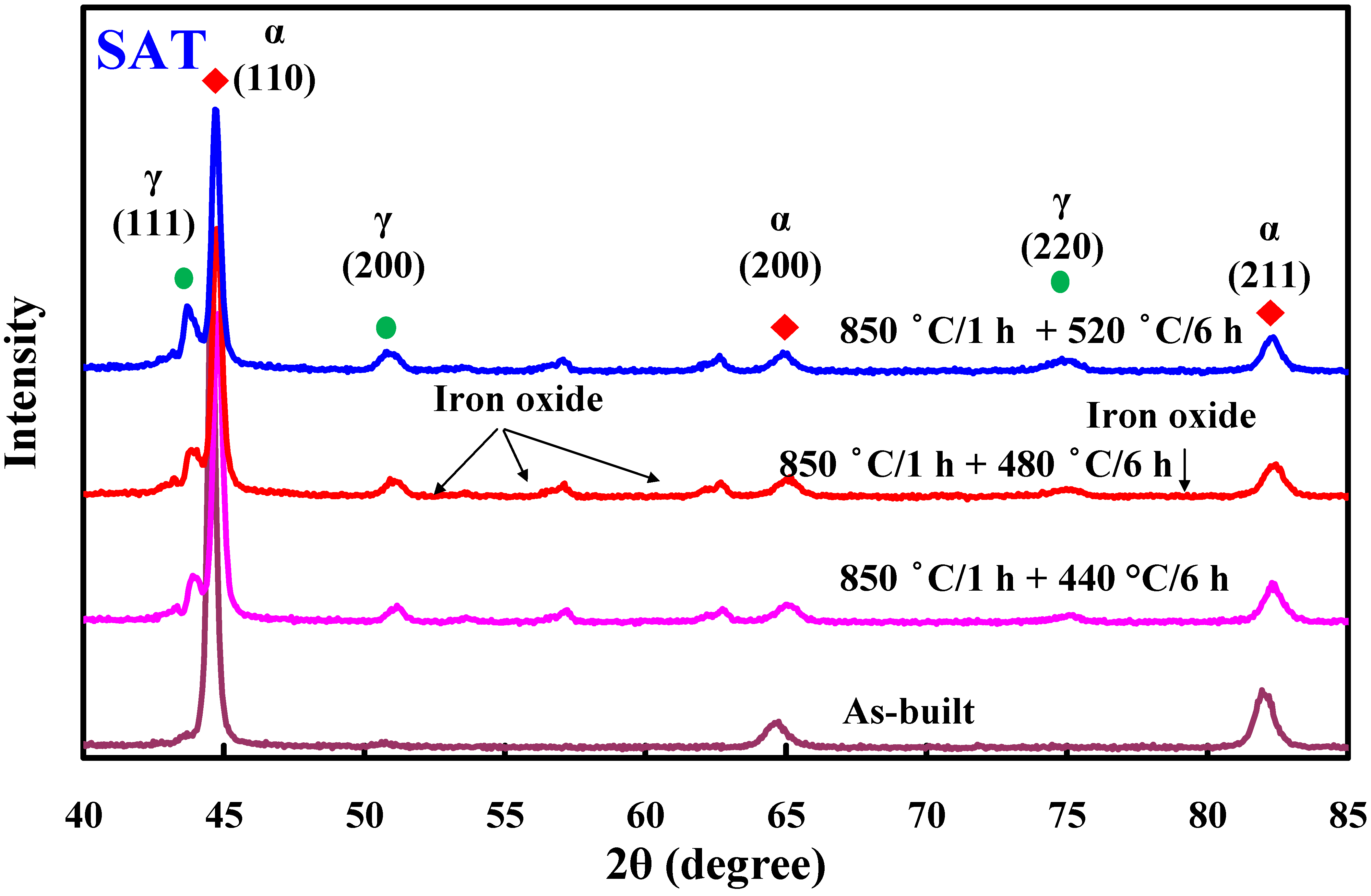
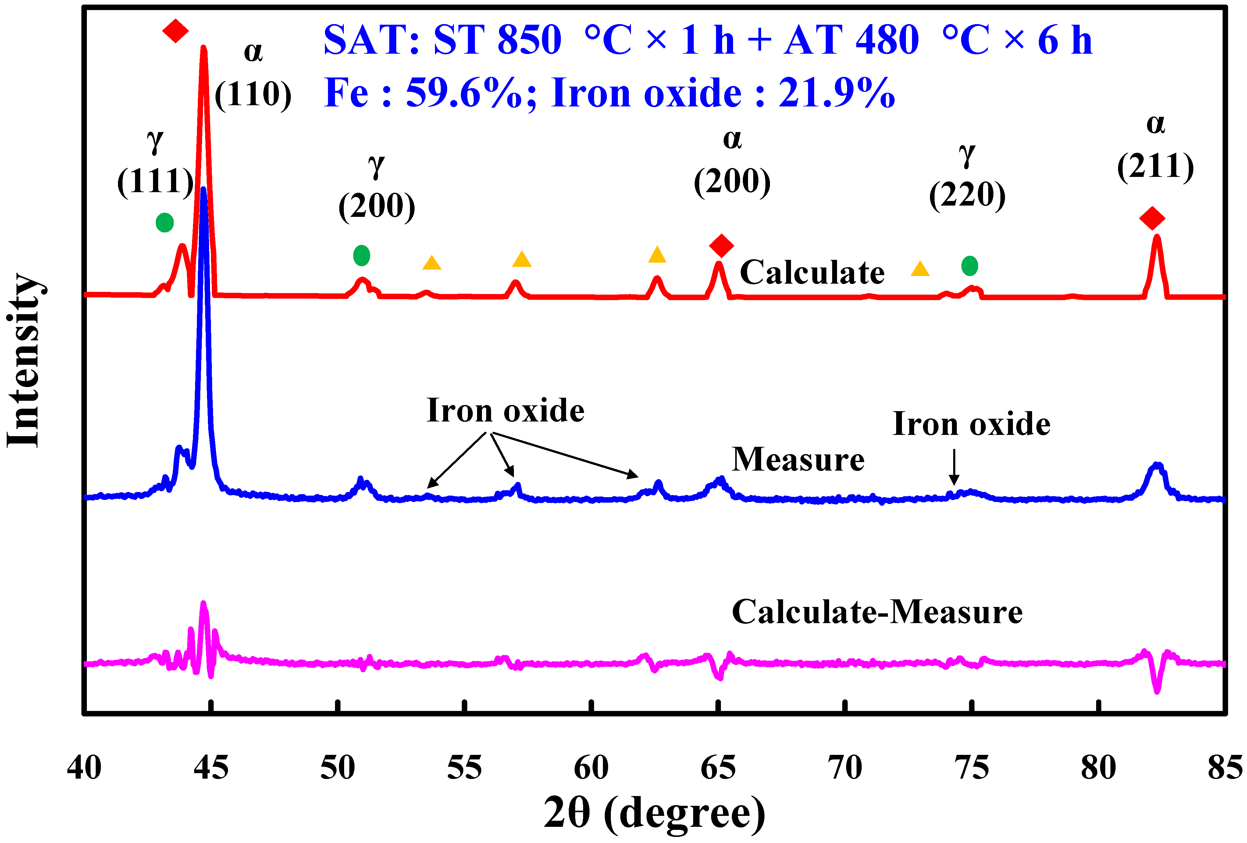
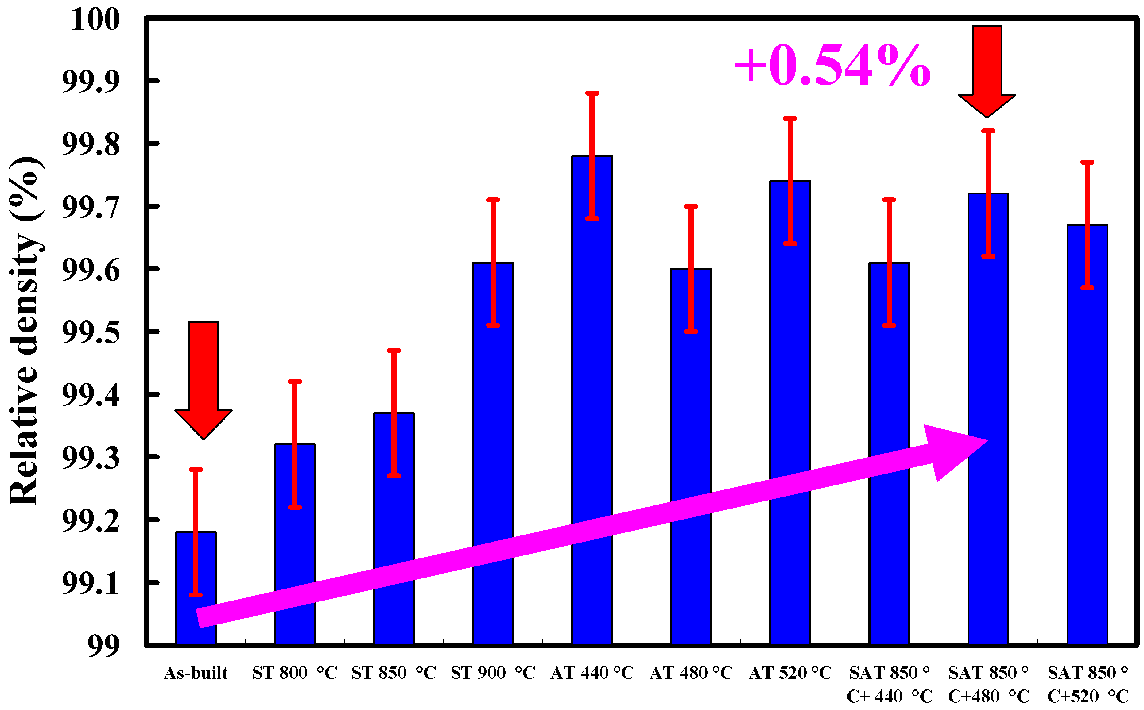
- The proposed simple approach solves the coolant leakage problem without any detrimental effects on the functions of either the CCC or the injection mold. The surface hardnesses of the injection mold were improved from HV 189 to HV 546 due to the Ni-Mo precipitates, increasing from 12.8 to 18.5%. The pore sizes were greatly reduced due to the iron oxide precipitates and the surface hardness of the injection mold was increased from 99.18 to 99.72%.
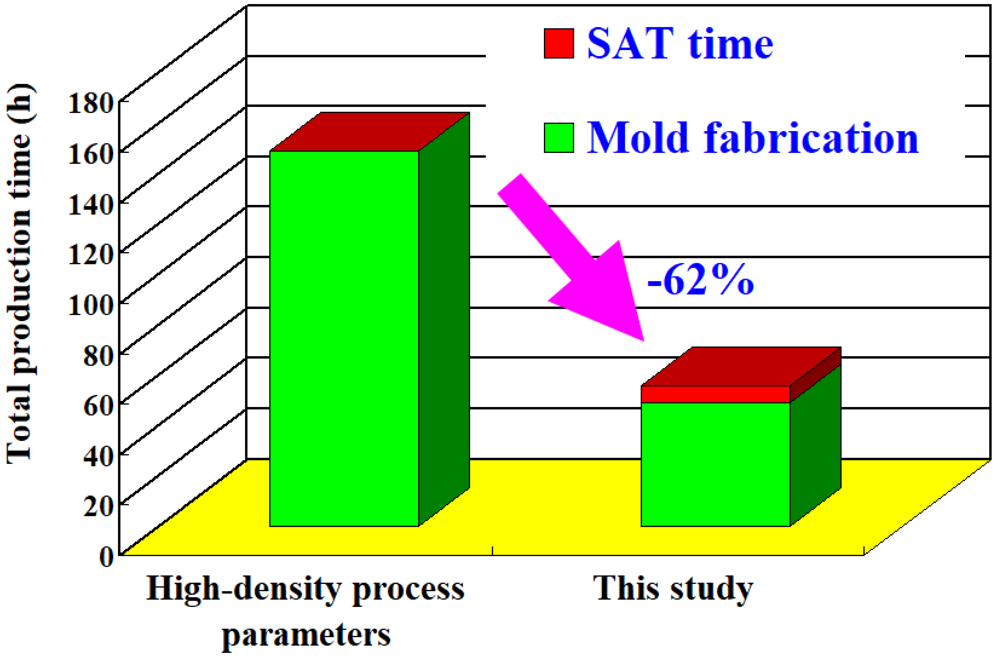
- The total production time of a wax injection mold without coolant leakage was only 62% that of a wax injection mold fabricated with high-density process parameters. In addition, up to 46% of production cost savings could be obtained when an injection mold is fabricated using general process parameters.
Author Contributions
Funding
Institutional Review Board Statement
Informed Consent Statement
Data Availability Statement
Conflicts of Interest
References
- Gor, M.; Soni, H.; Wankhede, V.; Sahlot, P.; Grzelak, K.; Szachgluchowicz, I.; Kluczyński, J. A critical review on effect of process parameters on mechanical and microstructural properties of powder-bed fusion additive manufacturing of SS316L. Materials 2021, 14, 6527. [Google Scholar] [CrossRef] [PubMed]
- Bedmar, J.; Riquelme, A.; Rodrigo, P.; Torres, B.; Rams, J. Comparison of different additive manufacturing methods for 316L Stainless Steel . Materials 2021, 14, 6504. [Google Scholar] [CrossRef]
- Ur Rehman, A.; Pitir, F.; Salamci, M.U. Full-field mapping and flow quantification of melt pool dynamics in laser powder bed fusion of SS316L. Materials 2021, 14, 6264. [Google Scholar] [CrossRef]
- Lucyshyn, T.; Des Enffans d’Avernas, L.-V.; Holzer, C. Influence of the mold material on the injection molding cycle time and warpage depending on the polymer processed. Polymers 2021, 13, 3196. [Google Scholar] [CrossRef]
- Mazzarisi, M.; Campanelli, S.L.; Angelastro, A.; Dassisti, M. Phenomenological modelling of direct laser metal deposition for single tracks. Int. J. Adv. Manuf. Technol. 2020, 111, 1955–1970. [Google Scholar] [CrossRef]
- Contaldi, V.; Del Re, F.; Palumbo, B.; Squillace, A.; Corrado, P.; Di Petta, P. Mechanical characterisation of stainless steel parts produced by direct metal laser sintering with virgin and reused powder. Int. J. Adv. Manuf. Technol. 2019, 105, 3337–3351. [Google Scholar] [CrossRef]
- Alafaghani, A.; Qattawi, A.; Castañón, M.A.G. Effect of manufacturing procedures on the microstructure and mechanical properties of metal laser sintering parts of precipitate hardenable metals. Int. J. Adv. Manuf. Technol. 2018, 99, 2491–2507. [Google Scholar] [CrossRef]
- AlMangour, B.; Yang, J. Understanding the deformation behavior of 17-4 precipitate hardenable stainless steel produced by direct metal laser sintering using micropillar compression and TEM. Int. J. Adv. Manuf. Technol. 2017, 90, 119–126. [Google Scholar] [CrossRef]
- Kundu, S.; Hussain, M.; Kumar, V.; Kumar, S.; Das, A.K. Direct metal laser sintering of TiN reinforced Ti6Al4V alloy based metal matrix composite: Fabrication and characterization. Int. J. Adv. Manuf. Technol. 2018, 97, 2635–2646. [Google Scholar] [CrossRef]
- Luo, Y.W.; Ma, T.; Shao, W.W.; Zhang, G.P.; Zhang, B. Effects of heat treatment on microstructures and mechanical properties of GH4169/K418 functionally graded material fabricated by laser melting deposition. Mater. Sci. Eng. A 2021, 821, 141601. [Google Scholar] [CrossRef]
- Cardon, A.; Mareau, C.; Ayed, Y.; Veen, S.V.D.; Giraud, E.; Santo, P.D. Heat treatment simulation of Ti-6Al-4V parts produced by selective laser melting. Addit. Manuf. 2021, 39, 101766. [Google Scholar] [CrossRef]
- Bai, Y.; Wang, D.; Yang, Y.Q.; Wang, H. Effect of heat treatment on the microstructure and mechanical properties of maraging steel by selective laser melting. Mater. Sci. Eng. A 2019, 760, 105–117. [Google Scholar] [CrossRef]
- Mutua, J.; Nakata, S.; Onda, T.; Chen, Z.C. Optimization of selective laser melting parameters and influence of post heat treatment on microstructure and mechanical properties of maraging steel. Mater. Des. 2018, 139, 486–497. [Google Scholar] [CrossRef]
- Song, J.; Tang, Q.; Feng, Q.; Ma, S.; Setchi, R.; Liu, Y.; Hanb, Q.; Fan, X.; Zhang, M. Effect of heat treatment on microstructure and mechanical behaviours of 18Ni-300 maraging steel manufactured by selective laser melting. Opt. Laser Technol. 2019, 120, 105725. [Google Scholar] [CrossRef]
- Bai, Y.; Yang, Y.; Wang, D.; Zhang, M. Influence mechanism of parameters process and mechanical properties evolution mechanism of maraging steel 300 by selective laser melting. Mater. Sci. Eng. A 2017, 703, 116–123. [Google Scholar] [CrossRef]
- Bodziak, S.; Al-Rubiae, K.S.; Valentina, L.D.; Lafratta, F.H.; Santos, E.C.; Zanatta, A.M.; Chen, Y. Precipitation in 300 grade maraging steel built by selective laser melting: Aging at 510 °C for 2 h. Mater. Charact. 2019, 151, 73–83. [Google Scholar] [CrossRef]
- Mudang, M.; Hamzah, E.; Bakhsheshi-Rad, H.R.; Berto, F. Effect of heat treatment on microstructure and creep behavior of Fe-40Ni-24Cr alloy. Appl. Sci. 2021, 11, 7951. [Google Scholar] [CrossRef]
- Chung, C.-Y.; Hwang, S.-S.; Chen, S.-C.; Lai, M.-C. Effects of injection molding process parameters on the chemical foaming behavior of polypropylene and polystyrene. Polymers 2021, 13, 2331. [Google Scholar] [CrossRef]
- Chen, J.-Y.; Liu, C.-Y.; Huang, M.-S. Tie-bar elongation based filling-to-packing switchover control and prediction of injection molding quality. Polymers 2019, 11, 1168. [Google Scholar] [CrossRef] [Green Version]
- Vieten, T.; Stahl, D.; Schilling, P.; Civelek, F.; Zimmermann, A. Feasibility study of soft tooling inserts for injection molding with integrated automated slides. Micromachines 2021, 12, 730. [Google Scholar] [CrossRef]
- Kroma, A.; Mendak, M.; Jakubowicz, M.; Gapiński, B.; Popielarski, P. Non-Contact Multiscale Analysis of a DPP 3D-Printed Injection Die for Investment Casting. Materials 2021, 14, 6758. [Google Scholar] [CrossRef]


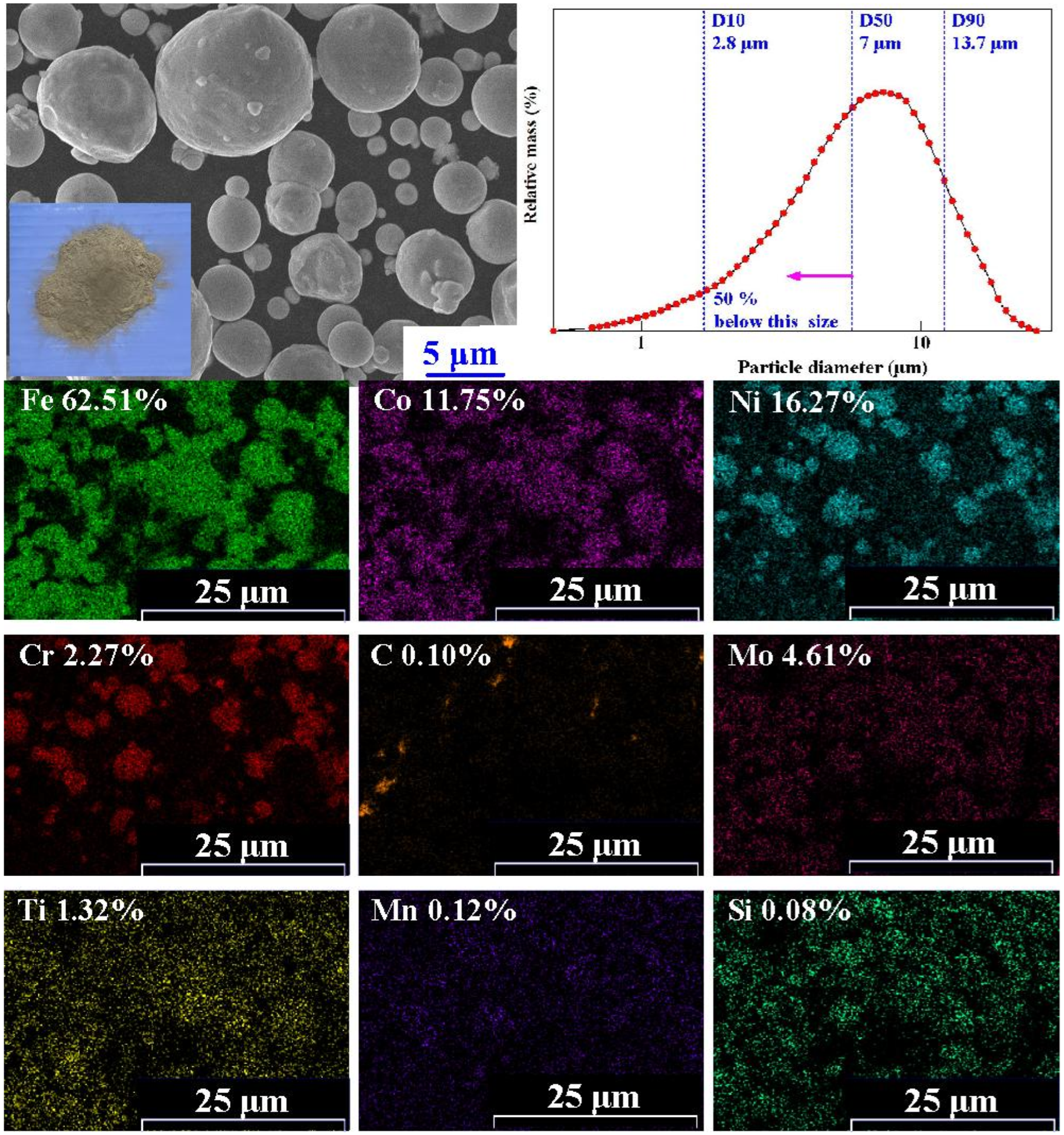
| Element | Ni | Co | Mo | Ti | Cr | Mn | Si |
|---|---|---|---|---|---|---|---|
| Wt.% | 16.27 | 11.75 | 4.61 | 1.32 | 2.27 | 0.12 | 0.08 |
| High Density | This Study | |
|---|---|---|
| Hatching space (µm) | 60 | 100 |
| Layer thickness (µm) | 30 | 50 |
| Laser power (W) | 50 | 40 |
| Scanning speed (mm/s) | 200 | 240 |
| Parameter | Value |
|---|---|
| Injection pressure (MPa) | 0.06 |
| Fill time (s) | 2 |
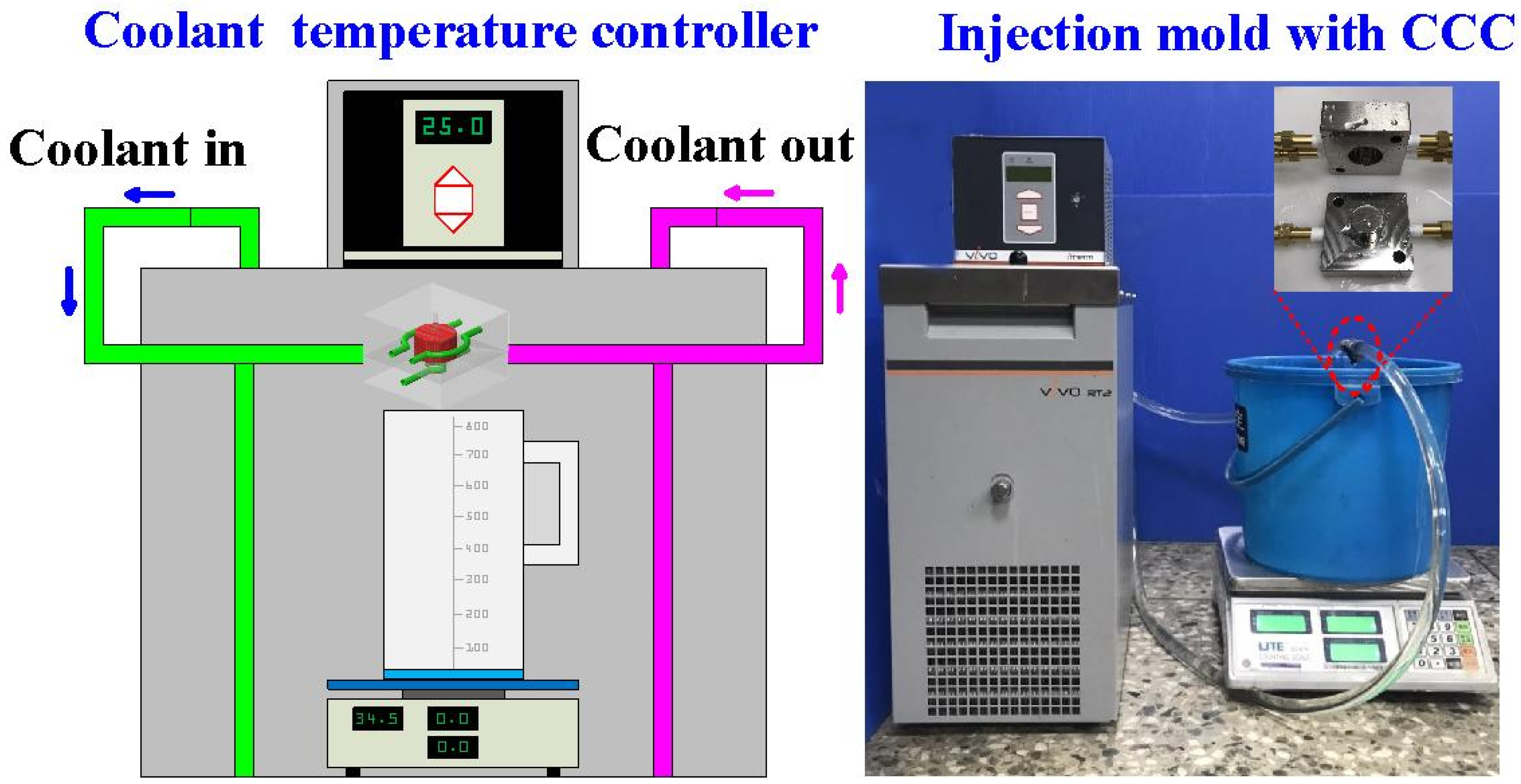
| Coolant temperature (°C) | 25 |
| Coolant flow rate (L/min) | 4 |
| Mold temperature (°C) | 27 |
| Injection temperature (°C) | 98 |
| Cycle time (s) | 49 |
Publisher’s Note: MDPI stays neutral with regard to jurisdictional claims in published maps and institutional affiliations. |
© 2021 by the authors. Licensee MDPI, Basel, Switzerland. This article is an open access article distributed under the terms and conditions of the Creative Commons Attribution (CC BY) license (https://creativecommons.org/licenses/by/4.0/).
Share and Cite
Kuo, C.-C.; Qiu, S.-X. A Simple Method of Reducing Coolant Leakage for Direct Metal Printed Injection Mold with Conformal Cooling Channels Using General Process Parameters and Heat Treatment. Materials 2021, 14, 7258. https://0-doi-org.brum.beds.ac.uk/10.3390/ma14237258
Kuo C-C, Qiu S-X. A Simple Method of Reducing Coolant Leakage for Direct Metal Printed Injection Mold with Conformal Cooling Channels Using General Process Parameters and Heat Treatment. Materials. 2021; 14(23):7258. https://0-doi-org.brum.beds.ac.uk/10.3390/ma14237258
Chicago/Turabian StyleKuo, Chil-Chyuan, and Shao-Xuan Qiu. 2021. "A Simple Method of Reducing Coolant Leakage for Direct Metal Printed Injection Mold with Conformal Cooling Channels Using General Process Parameters and Heat Treatment" Materials 14, no. 23: 7258. https://0-doi-org.brum.beds.ac.uk/10.3390/ma14237258