
The Importance of Structural Factors for the Electrochemical Performance of Graphene/Carbon Nanotube/Melamine Powders towards the Catalytic Activity of Oxygen Reduction Reaction

 ,
,
Abstract
:1. Introduction
2. Materials and Methods
2.1. Materials
2.2. Composite Preparation
2.3. Material Characterization
2.4. Electrochemical Measurements
3. Results
4. Conclusions
Author Contributions
Funding
Institutional Review Board Statement
Informed Consent Statement
Data Availability Statement
Conflicts of Interest
References
- Lee, C.; Wei, X.; Kysar, J.W.; Hone, J. Measurement of the elastic properties and intrinsic strength of monolayer graphene. Science 2008, 321, 385–388. [Google Scholar] [CrossRef]
- Demczyk, B.G.; Wang, Y.M.; Cumings, J.; Hetman, M.; Han, W.; Zettl, A.; Ritchie, R.O. Direct mechanical measurement of the tensile strength and elastic modulus of multiwalled carbon nanotubes. Mater. Sci. Eng. A 2008, 334, 173–178. [Google Scholar] [CrossRef]
- Balandin, A.A. Thermal properties of graphene and nanostructured carbon materials. Nat. Mater. 2011, 10, 569–581. [Google Scholar] [CrossRef] [PubMed] [Green Version]
- Volkov, A.N.; Zhigilei, L.V. Heat conduction in carbon nanotube materials: Strong effect of intrinsic thermal conductivity of carbon nanotubes. Appl. Phys. Lett. 2012, 101, 043113. [Google Scholar] [CrossRef] [Green Version]
- Murata, H.; Nakajima, Y.; Saitoh, N.; Yoshizawa, N.; Suemasu, T.; Toko, K. High-Electrical-Conductivity Multilayer Graphene Formed by Layer Exchange with Controlled Thickness and Interlayer. Sci. Rep. 2019, 9, 4068. [Google Scholar] [CrossRef] [Green Version]
- Vargas-Lara, F.; Hassan, A.M.; Garboczi, E.J.; Douglas, J.F. Intrinsic conductivity of carbon nanotubes and graphene sheets having a realistic geometry. J. Chem. Phys. 2015, 143, 204902. [Google Scholar] [CrossRef]
- Gadipelli, S.; Guo, Z.X. Graphene-based materials: Synthesis and gas sorption, storage and separation. Prog. Mater. Sci. 2015, 69, 1–60. [Google Scholar] [CrossRef] [Green Version]
- Peigney, A.; Laurent, C.; Flahaut, E.; Bacsa, R.R.; Rousset, A. Specific surface area of carbon nanotubes and bundles of carbon nanotubes. Carbon 2001, 39, 507–514. [Google Scholar] [CrossRef] [Green Version]
- Yu, D.; Dai, L. Self-assembled graphene/carbon nanotube hybrid films for supercapacitors. J. Phys. Chem. Lett. 2010, 1, 467–470. [Google Scholar] [CrossRef]
- Du, F.; Yu, D.; Dai, L.; Ganguli, S.; Varshney, V.; Roy, A.K. Preparation of tunable 3D pillared carbon nanotube-graphene networks for high-performance capacitance. Chem. Mater. 2011, 23, 4810–4816. [Google Scholar] [CrossRef]
- Chen, Z.; Lv, T.; Yao, Y.; Li, H.; Li, N.; Yang, Y.; Liu, K.; Qian, G.; Wang, X.; Chen, T. Three-dimensional seamless graphene/carbon nanotube hybrids for multifunctional energy storage. J. Mater. Chem. A 2019, 7, 24792–24799. [Google Scholar] [CrossRef]
- Kshetri, T.; Tran, D.T.; Nguyen, D.C.; Kim, N.H.; Lau, K.; Lee, J.H. Ternary graphene-carbon nanofibers-carbon nanotubes structure for hybrid supercapacitor. Chem. Eng. J. 2020, 380, 122543. [Google Scholar] [CrossRef]
- Vinayan, B.P.; Nagar, R.; Raman, V.; Rajalakshmi, N.; Dhathathreyan, K.S.; Ramaprabhu, S. Synthesis of graphene-multiwalled carbon nanotubes hybrid nanostructure by strengthened electrostatic interaction and its lithium ion battery application. J. Mater. Chem. 2012, 22, 9949–9956. [Google Scholar] [CrossRef]
- Wang, W.; Ruiz, I.; Guo, S.; Favors, Z.; Bay, H.H.; Ozkan, M.; Ozkan, C.S. Hybrid carbon nanotube and graphene nanostructures for lithium ion battery anodes. Nano Energy 2014, 3, 113–118. [Google Scholar] [CrossRef]
- Xie, Z.; He, Z.; Feng, X.; Xu, W.; Cui, X.; Zhang, J.; Yan, C.; Carreon, M.A.; Liu, Z.; Wang, Y. Hierarchical Sandwich-Like Structure of Ultrafine N-Rich Porous Carbon Nanospheres Grown on Graphene Sheets as Superior Lithium-Ion Battery Anodes. ACS Appl. Mater. Interfaces 2016, 8, 10324–10333. [Google Scholar] [CrossRef] [PubMed]
- Kim, H.; Kim, J.; Jeong, H.-S.; Kim, H.; Lee, H.; Ha, J.-M.; Choi, S.-M.; Kim, T.-H. Spontaneous hybrids of graphene and carbon nanotube arrays at the liquid-gas interface for Li-ion battery anodes. Chem. Commun. 2018, 54, 5229–5232. [Google Scholar] [CrossRef] [PubMed]
- Sun, L.; Kong, W.; Jiang, Y.; Wu, H.; Jiang, K.; Wang, J.; Fan, S. Super-aligned carbon nanotube/graphene hybrid materials as a framework for sulfur cathodes in high performance lithium sulfur batteries. J. Mater. Chem. A 2015, 3, 5305–5312. [Google Scholar] [CrossRef]
- Song, J.; Yu, Z.; Gordin, M.L.; Wang, D. Advanced Sulfur Cathode Enabled by Highly Crumpled Nitrogen-Doped Graphene Sheets for High-Energy-Density Lithium-Sulfur Batteries. Nano Lett. 2016, 16, 864–870. [Google Scholar] [CrossRef]
- Huang, J.Q.; Xu, Z.L.; Abouali, S.; Garakani, M.A.; Kim, J.K. Porous graphene oxide/carbon nanotube hybrid films as interlayer for lithium-sulfur batteries. Carbon 2016, 99, 624–632. [Google Scholar] [CrossRef]
- Ilnicka, A.; Skorupska, M.; Romanowski, P.; Kamedulski, P.; Lukaszewicz, J.P. Improving the Performance of Zn-Air Batteries with N-Doped Electroexfoliated Graphene. Materials 2020, 13, 2115. [Google Scholar] [CrossRef] [PubMed]
- Cai, X.; Xia, B.Y.; Franklin, J.; Li, B.; Wang, X.; Wang, Z.; Chen, L.; Lin, J.; Lai, L.; Shen, Z. Free-standing vertically-aligned nitrogen-doped carbon nanotube arrays/graphene as air-breathing electrodes for rechargeable zinc-air batteries. J. Mater. Chem. A 2017, 5, 2488–2495. [Google Scholar] [CrossRef]
- Yang, W.; Zhang, Y.; Liu, X.; Chen, L.; Jia, J. In situ formed Fe-N doped metal organic framework@carbon nanotubes/graphene hybrids for a rechargeable Zn-air battery. Chem. Commun. 2017, 53, 12934–12937. [Google Scholar] [CrossRef]
- Xu, Y.; Deng, P.; Chen, G.; Chen, J.; Yan, Y.; Qi, K.; Liu, H.; Xia, B.Y. 2D Nitrogen-Doped Carbon Nanotubes/Graphene Hybrid as Bifunctional Oxygen Electrocatalyst for Long-Life Rechargeable Zn-Air Batteries. Adv. Funct. Mater. 2020, 30, 1906081. [Google Scholar] [CrossRef]
- Paul, R.; Zhu, L.; Chen, H.; Qu, J.; Dai, L. Recent Advances in Carbon-Based Metal-Free Electrocatalysts. Adv. Mater. 2019, 31, 1806403. [Google Scholar] [CrossRef] [PubMed]
- Kamedulski, P.; Kaczmarek-Kedziera, A.; Lukaszewicz, J.P. Influence of intermolecular interactions on the properties of carbon nanotubes. Bull. Mater. Sci. 2018, 41, 76. [Google Scholar] [CrossRef] [Green Version]
- Jha, N.; Jafri, R.I.; Rajalakshmi, N.; Ramaprabhu, S. Graphene-multi walled carbon nanotube hybrid electrocatalyst support material for direct methanol fuel cell. Int. J. Hydrog. Energy 2011, 36, 7284–7290. [Google Scholar] [CrossRef]
- Jyothirmayee Aravind, S.S.; Imran Jafri, R.; Rajalakshmi, N.; Ramaprabhu, S. Solar exfoliated graphene-carbon nanotube hybrid nano composites as efficient catalyst supports for proton exchange membrane fuel cells. J. Mater. Chem. 2011, 21, 18199–18204. [Google Scholar] [CrossRef]
- Pham, K.-C.; McPhail, D.S.; Mattevi, C.; Wee, A.T.S.; Chua, D.H.C. Graphene-Carbon Nanotube Hybrids as Robust Catalyst Supports in Proton Exchange Membrane Fuel Cells. J. Electrochem. Soc. 2016, 163, F255–F263. [Google Scholar] [CrossRef] [Green Version]
- Iqbal, M.Z.; Rehman, A.U.; Siddique, S. Prospects and challenges of graphene based fuel cells. J. Energy Chem. 2019, 39, 217–234. [Google Scholar] [CrossRef] [Green Version]
- Paraknowitsch, J.P.; Thomas, A. Doping carbons beyond nitrogen: An overview of advanced heteroatom doped carbons with boron, sulphur and phosphorus for energy applications. Energy Environ. Sci. 2013, 6, 2839–2855. [Google Scholar] [CrossRef] [Green Version]
- Kamedulski, P.; Truszkowski, S.; Lukaszewicz, J.P. Highly Effective Methods of Obtaining N-Doped Graphene by Gamma Irradiation. Materials 2020, 13, 4975. [Google Scholar] [CrossRef]
- Ding, Y.L.; Kopold, P.; Hahn, K.; Van Aken, P.A.; Maier, J.; Yu, Y. Facile Solid-State Growth of 3D Well-Interconnected Nitrogen-Rich Carbon Nanotube-Graphene Hybrid Architectures for Lithium-Sulfur Batteries. Adv. Funct. Mater. 2016, 26, 1112–1119. [Google Scholar] [CrossRef]
- Coros, M.; Varodi, C.; Pogacean, F.; Gal, E.; Pruneanu, S.M. Nitrogen-doped graphene: The influence of doping level on the charge-transfer resistance and apparent heterogeneous electron transfer rate. Sensors 2020, 20, 1815. [Google Scholar] [CrossRef] [Green Version]
- Wei, Q.; Tong, X.; Zhang, G.; Qiao, J.; Gong, Q.; Sun, S. Nitrogen-doped carbon nanotube and graphene materials for oxygen reduction reactions. Catalysts 2015, 5, 1574–1602. [Google Scholar] [CrossRef] [Green Version]
- Svintsitskiy, D.A.; Kibis, L.S.; Smirnov, D.A.; Suboch, A.N.; Stonkus, O.A.; Podyacheva, O.Y.; Boronin, A.I.; Ismagilov, Z.R. Spectroscopic study of nitrogen distribution in N-doped carbon nanotubes and nanofibers synthesized by catalytic ethylene-ammonia decomposition. Appl. Surf. Sci. 2018, 435, 1273–1284. [Google Scholar] [CrossRef]
- Szroeder, P.; Tsierkezos, N.G.; Scharff, P.; Ritter, U. Electrocatalytic properties of carbon nanotube carpets grown on Si-wafers. Carbon 2010, 48, 4489–4496. [Google Scholar] [CrossRef]
- Lu, A.-H.; Zhao, D.; Wan, Y. Nanocasting: A Versatile Strategy for Creating Nanostructured Porous Materials, 1st ed.; RSC Publishing: London, UK, 2009; pp. 1–265. [Google Scholar]
- Lei, H.Y.; Piao, J.-H.; Brouzgou, A.; Gorbova, E.; Tsiakaras, P.; Liang, Z.-X. Synthesis of nitrogen-doped mesoporous carbon nanosheets for oxygen reduction electrocatalytic activity enhancement in acid and alkaline media. Int. J. Hydrog. Energy 2019, 44, 4423–4431. [Google Scholar] [CrossRef]
- Brouzgou, A.; Gorbova, E.; Wang, Y.; Jing, S.; Seretis, A.; Liang, Z.; Tsiakaras, P. Nitogen-doped 3D hierarchical ordered mesoporous carbon supported palladium electrocatalyst for the simultaneous detection of ascorbic acid, dopamine, and glucose. Ionics 2019, 25, 6061–6070. [Google Scholar] [CrossRef]
- Liu, X.; Hao, J.; Gaan, S. Recent studies on the decomposition and strategies of smoke and toxicity suppression for polyurethane based materials. RSC Adv. 2016, 6, 74742–74756. [Google Scholar] [CrossRef] [Green Version]
- König, A.; Fehrenbacher, U.; Kroke, E.; Hirth, T. Thermal decomposition behavior of the flame retardant melamine in slabstock flexible polyurethane foams. J. Fire Sci. 2009, 27, 187–211. [Google Scholar] [CrossRef]
- Lotsch, B.V.; Schnick, W. New light on an old story: Formation of melam during thermal condensation of melamine. Chem. A Eur. J. 2007, 13, 4956–4968. [Google Scholar] [CrossRef] [PubMed]
- Yan, X.-L.; Li, H.-F.; Wang, C.; Jiang, B.-B.; Hu, H.-Y.; Xie, N.; Wu, M.H.; Vinodgopal, K.; Dai, G.-P. Melamine as a single source for fabrication of mesoscopic 3D composites of N-doped carbon nanotubes on graphene. RSC Adv. 2018, 8, 12157–12164. [Google Scholar] [CrossRef] [Green Version]
- Li, H.-F.; Wu, F.; Wang, C.; Zhang, P.-X.; Hu, H.-Y.; Xie, N.; Pan, M.; Zeng, Z.; Deng, S.; Wu, M.H.; et al. One-Step Chemical Vapor Deposition Synthesis of 3D N-doped Carbon Nanotube/N-doped Graphene Hybrid Material on Nickel Foam. Nanomaterials 2018, 8, 700. [Google Scholar] [CrossRef] [PubMed] [Green Version]
- Kamedulski, P.; Ilnicka, A.; Lukaszewicz, J.P.; Skorupska, M. Highly effective three-dimensional functionalization of graphite to graphene by wet chemical exfoliation methods. Adsorption 2019, 25, 631–638. [Google Scholar] [CrossRef] [Green Version]
- Ilnicka, A.; Kamedulski, P.; Skorupska, M.; Lukaszewicz, J.P. Metal-free nitrogen-rich carbon foam derived from amino acids for the oxygen reduction reaction. J. Mater. Sci. 2019, 54, 14859–14871. [Google Scholar] [CrossRef] [Green Version]
- Davis, R.E.; Horvath, G.L.; Tobias, C.W. The solubility and diffusion coefficient of oxygen in potassium hydroxide solutions. Electrochim. Acta 1967, 12, 287–297. [Google Scholar] [CrossRef]
- Mircescu, N.E.; Oltean, M.; Chis, V.; Leopold, N. FTIR, FT-Raman, SERS and DFT study on melamine. Vib. Spectrosc. 2012, 62, 165–171. [Google Scholar] [CrossRef]
- Mueller, N.S.; Heeg, S.; Alvarez, M.P.; Kusch, P.; Wasserroth, S.; Clark, N.; Schedin, F.; Parthenios, J.; Papagelis, K.; Galiotis, C.; et al. Evaluating arbitrary strain configurations and doping in graphene with Raman spectroscopy. 2D Mater. 2018, 5, 015016. [Google Scholar] [CrossRef]
- Froehlicher, G.; Berciaud, S. Raman spectroscopy of electrochemically gated graphene transistors: Geometrical capacitance, electron-phonon, electron-electron, and electron-defect scattering. Phys. Rev. B Condens. Matter Mater. Phys. 2015, 91, 205413. [Google Scholar] [CrossRef] [Green Version]
- Rao, C.N.R.; Voggu, R. Charge-transfer with graphene and nanotubes. Mater. Today 2010, 13, 34–40. [Google Scholar] [CrossRef]
- Cancado, L.G.; Jorio, A.; Martins Ferreira, E.H.; Stavale, F.; Achete, C.A.; Capaz, R.B.; Moutinho, M.V.O.; Lombardo, A.; Kulmala, T.S.; Ferrari, A.C. Quantifying defects in graphene via Raman spectroscopy at different excitation energies. Nano Lett. 2011, 11, 3190–3196. [Google Scholar] [CrossRef] [PubMed] [Green Version]
- Li, Q.; Kang, Y.-L.; Qiu, W.; Li, Y.-L.; Huang, G.-Y.; Guo, J.-G.; Deng, W.-L.; Zhong, X.-H. Deformation mechanisms of carbon nanotube fibres under tensile loading by in situ Raman spectroscopy analysis. Nanotechnology 2011, 22, 225704. [Google Scholar] [CrossRef] [PubMed]
- Zhai, H.-S.; Cao, L.; Xia, X.-H. Synthesis of graphitic carbon nitride through pyrolysis of melamine and its electrocatalysis for oxygen reduction reaction. Chin. Chem. Lett. 2013, 24, 103–106. [Google Scholar] [CrossRef]


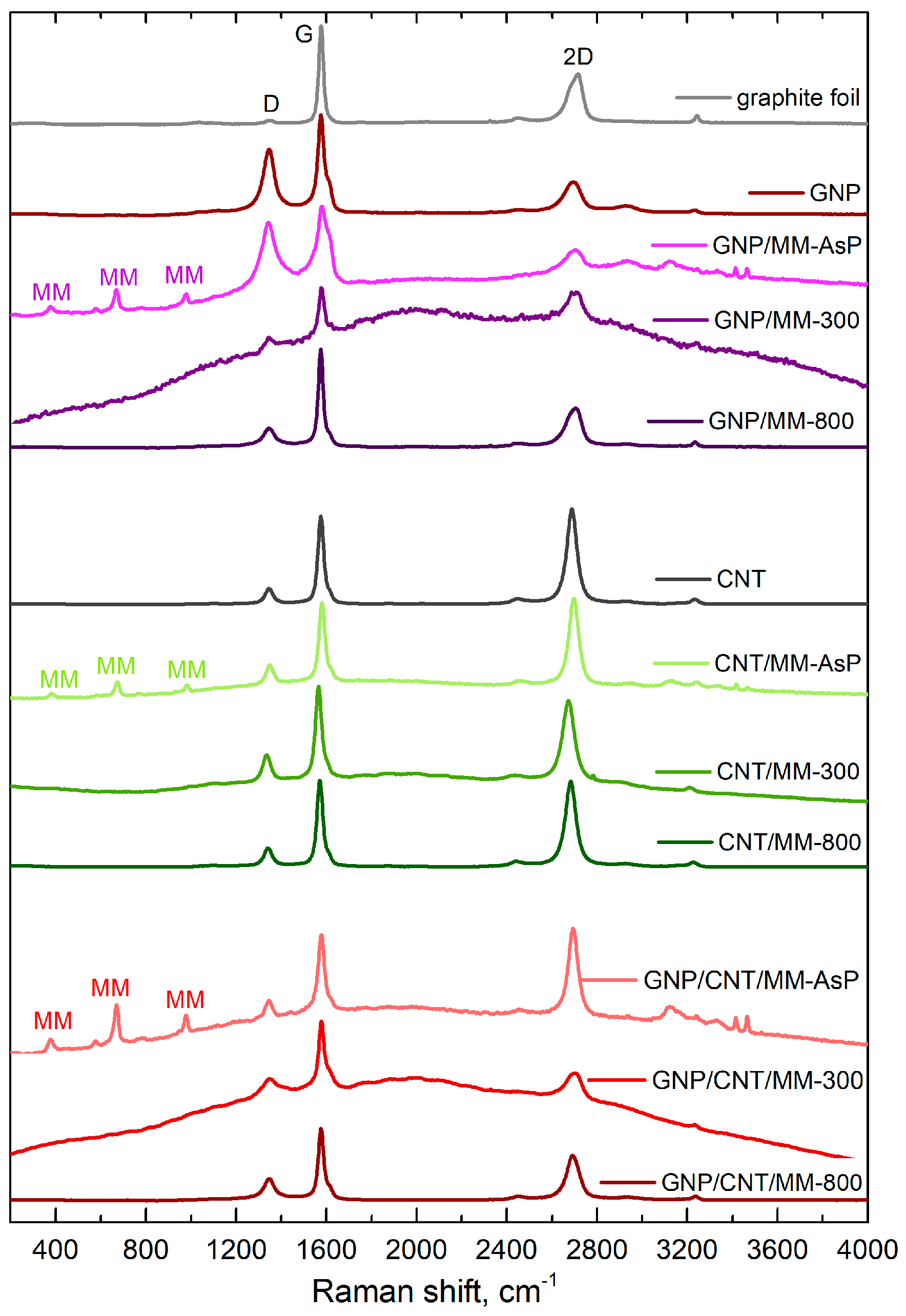
| Sample | D (cm−1) | G (cm−1) | 2D (cm−1) | ID/IG | nd (×1010 cm−2) | I2D/IG |
|---|---|---|---|---|---|---|
| graphite foil | 1348.5 | 1576.28 | 2719.52 | 0.027 | 0.62 | 0.331 |
| GNP | 1344.6 | 1576.43 | 2691.29 | 0.680 | 15.27 | 0.326 |
| GNP/MM-AsP | 1343.1 | 1586.06 | 2693.84 | 0.797 | 17.91 | 0.264 |
| GNP/MM-300 | 1349.6 | 1578.15 | 2700.87 | 0.233 | 5.24 | 0.658 |
| GNP/MM-800 | 1345.4 | 1574.71 | 2697.40 | 0.181 | 4.06 | 0.411 |
| CNT | 1345.4 | 1575.35 | 2688.09 | 0.172 | 3.87 | 1.08 |
| CNT/MM-AsP | 1348.4 | 1580.33 | 2696.45 | 0.251 | 5.63 | 1.106 |
| CNT/MM-300 | 1334.8 | 1566.35 | 2675.88 | 0.178 | 4.01 | 0.907 |
| CNT/MM-800 | 1341.1 | 1571.04 | 2682.73 | 0.208 | 4.67 | 0.985 |
| GNP/CNT/M-AsP | 1343.5 | 1576.90 | 2693.32 | 0.225 | 5.06 | 1.170 |
| GNP/CNT/M-300 | 1351.2 | 1578.34 | 2693.28 | 0.255 | 5.72 | 0.434 |
| GNP/CNT/M-800 | 1345.8 | 1576.23 | 2692.56 | 0.284 | 6.38 | 0.640 |
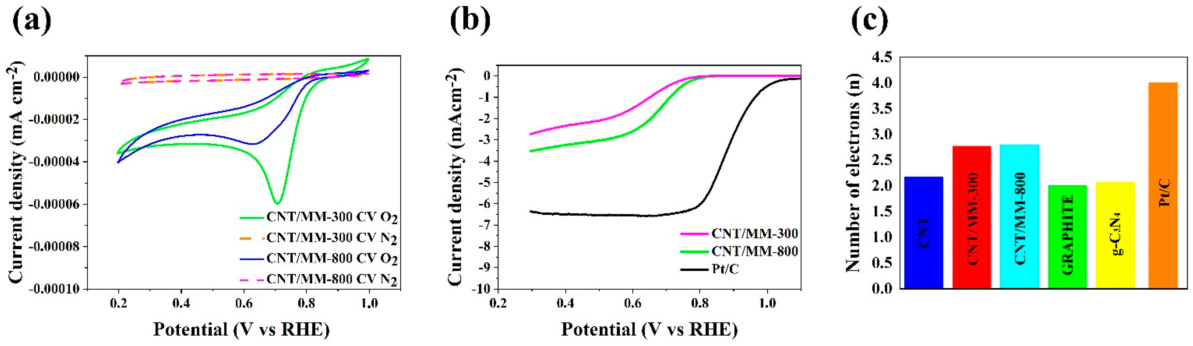
| Catalysts | Ep (V vs. RHE) | Eonset (V vs. RHE) | E1/2 (V vs. RHE) | Diffusion-Limiting Current (mA cm−2) | n (0.5 V) |
|---|---|---|---|---|---|
| Pt/C (20% wt.) | 0.76 | 1.030 | 0.88 | 6.37 | 4.00 |
| CNT/MM-300 | 0.77 | 0.759 | 0.72 | 3.08 | 2.77 |
| CNT/MM-800 | 0.78 | 0.772 | 0.74 | 3.26 | 2.80 |
Publisher’s Note: MDPI stays neutral with regard to jurisdictional claims in published maps and institutional affiliations. |
© 2021 by the authors. Licensee MDPI, Basel, Switzerland. This article is an open access article distributed under the terms and conditions of the Creative Commons Attribution (CC BY) license (https://creativecommons.org/licenses/by/4.0/).
Share and Cite
Kamedulski, P.; Lukaszewicz, J.P.; Witczak, L.; Szroeder, P.; Ziolkowski, P. The Importance of Structural Factors for the Electrochemical Performance of Graphene/Carbon Nanotube/Melamine Powders towards the Catalytic Activity of Oxygen Reduction Reaction. Materials 2021, 14, 2448. https://0-doi-org.brum.beds.ac.uk/10.3390/ma14092448
Kamedulski P, Lukaszewicz JP, Witczak L, Szroeder P, Ziolkowski P. The Importance of Structural Factors for the Electrochemical Performance of Graphene/Carbon Nanotube/Melamine Powders towards the Catalytic Activity of Oxygen Reduction Reaction. Materials. 2021; 14(9):2448. https://0-doi-org.brum.beds.ac.uk/10.3390/ma14092448
Chicago/Turabian StyleKamedulski, Piotr, Jerzy P. Lukaszewicz, Lukasz Witczak, Pawel Szroeder, and Przemyslaw Ziolkowski. 2021. "The Importance of Structural Factors for the Electrochemical Performance of Graphene/Carbon Nanotube/Melamine Powders towards the Catalytic Activity of Oxygen Reduction Reaction" Materials 14, no. 9: 2448. https://0-doi-org.brum.beds.ac.uk/10.3390/ma14092448