Article

Active Meta-Device for Dual-Transmission Windows with Tunable Angular Dispersion Characteristics

1
Department of Basic Sciences, Air Force Engineering University, Xi’an 710051, China
2
Shannxi Key Laboratory of Artificially-Structured Functional Materials and Devices, Xi’an 710051, China
*
Author to whom correspondence should be addressed.
These authors contributed equally to this work.
Submission received: 22 April 2022 / Revised: 11 May 2022 / Accepted: 16 May 2022 / Published: 20 May 2022

Abstract

:
Tailoring electromagnetic properties by meta-devices has aroused great interest with respect to manipulating light. However, the uncertainty of angular dispersion introduced by the incident waves prevents their further applications. Here, we propose a general paradigm for achieving dual-transmission windows while simultaneously eliminating the corresponding angular dispersions by a dynamic manner. The strategy of loading varactor diodes into a plasmonic meta-atom is used. In this way, the blue shifts of angular dispersion can be dynamically compensated by the red shifts introduced by the varactor diodes when driven by bias voltage. As a proof-of-principle, an active meta-atom with varactor diodes is presented. The varactor diodes embedded can independently regulate dual-transmission windows. The test results are consistent with the simulation ones. The presented meta-device is used for intelligent radome, angle-multiplexed communications, and incident-angle-insensitive equipment while providing tunable angular dispersion properties.

1. Introduction

In the past few decades, the emerging metamaterials have been intensively researched and developed in the electromagnetic (EM) community [1]. Metasurfaces, the 2D equivalent of metamaterials, are artificial subwavelength structures that regulate electromagnetic (EM) waves [2]. The emergence of 4D technology has led to a closer relationship between structure and performance [3]. They can achieve unique characteristics that can hardly be found in natural materials. They can be applied in microwave, acoustic, and visible regions, including vortex beams [4,5], light refraction [6,7], and invisibility cloaks [8]. Under normal incidence conditions, most of these modulation effects can be achieved [9,10]. However, as the angle of incidence increases, the angular dispersion inevitably affects the EM properties of the metasurface. Nowadays, active metasurfaces [11,12] have provided a dynamic and flexible approach to achieve electromagnetic regulation. Active components [13,14] or phase-change materials [15,16] have been introduced to achieve reconfigurable properties. They are more flexible and diverse in efficiently regulating the amplitude, phase, and polarization of EM waves [17,18]. In 2014, a programmable metasurface was presented to modulate EM waves in a programmable way [19]. The functional regulation of the far field and near field can be provided by simply changing the digital coding sequences [20,21,22].
In different application scenarios, the angular dispersion is a vital issue that requires solving. One of the angular dispersions for transmission windows is the resonant frequency shift, which will influence transmission characteristics. With the rapid development of modern communication and antenna systems, the meta-device of dual-transmission windows without angular dispersion is urgently required. Wide-angle meta-devices [23,24] and angle-multiplexed meta-devices [25,26,27] are designed to eliminate the effect of angular dispersion. However, they were obtained through brute-force simulation. In [28], the angular dispersions in metasurfaces were revealed by near-field couplings (NFCs) among adjacent meta-atoms, but the experimental demonstrations were limited to low-frequency domains. The underlying mechanisms of angular dispersions still need to be further explored and developed. By introducing active components, active metasurfaces can achieve multifunctional and continuous modulation of EM waves, including amplitude, phase, and polarization. In this way, active metasurfaces possess the great potential to become an adequate candidate to eliminate the effect of angular dispersion in a dynamic way.
In this paper, a general paradigm for tunable angular dispersion with active components is proposed. The method of loading the varactor diodes into passive meta-atom is employed to tune the angular dispersion. With the increase of the incident angle, the blue shifts of the angular dispersion appear. Simultaneously, the red shifts are introduced by the varactor diodes when driven by bias voltage. Red shifts and blue shifts counteract each other to achieve angular dispersion compensation. A triple-layer meta-device with active components is proposed as a proof-of-principle. Varactor diodes are, respectively, embedded on the top and bottom layer. They can independently regulate the resonant frequency of the transmission window. According to the simulation and test results, the proposed structure provides a dynamic method for regulating the angular dispersion. This makes it a great prospect for applications in incident-angle-insensitive meta-devices and angle-multiplexed communications.

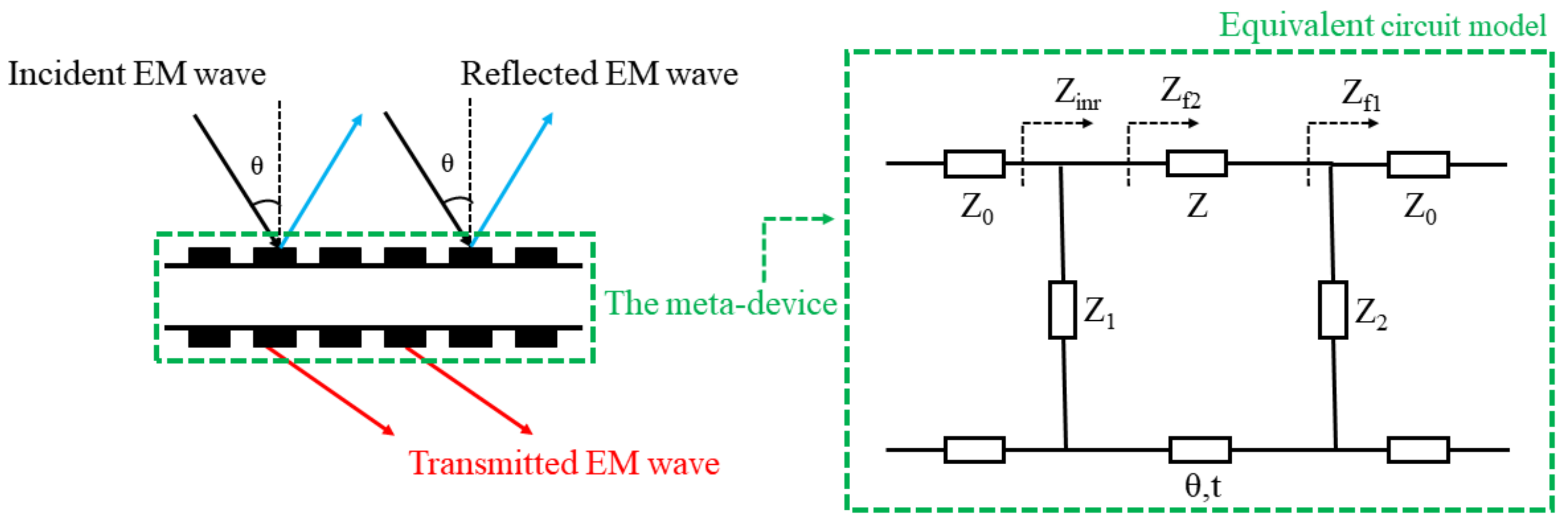
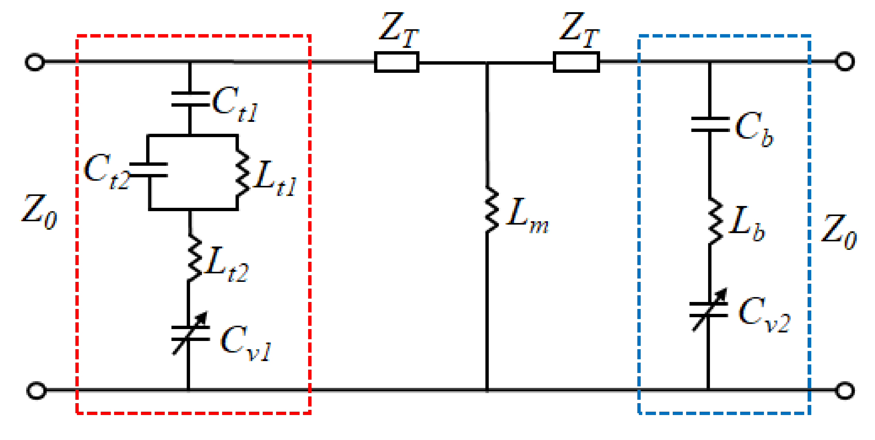
2. Underlying Mechanism

The meta-device can be regarded as a combination of various impedances by the equivalent circuit model (ECM). The ECM provides a method to achieve tunable angular dispersion by adjusting the equivalent impedance.
As shown in Figure 1, when the EM wave is incident, the meta-device divides it into two parts: the reflected EM wave and the transmitted EM wave. Here, the frequency of the transmitted EM wave is determined by the equivalent impedance of the meta-device. According to transmission line theory [29], the reflection and transmission coefficients of the equivalent circuit are calculated from Equations (1) and (2):
S 11 = Z i n r Z 0 Z i n r + Z 0 ,
S 21 = 2 2 + Z Z 1 + Z Z 2 cos β t + j 2 + Z Z 1 + Z Z 2 + Z 2 Z 1 Z 2 sin β t ,
with
Z i n r = Z f 2 Z 1 Z f 2 + Z 1 ,   Z f 2 = Z Z f 1 + j Z tan β t Z + j Z f 1 tan β t ,   Z f 1 = Z 2 Z 0 Z 2 + Z 0 , Z 0 = μ 0 ε 0 377 Ω ,
and
β = 2 π f c 0 .
Z0, Z1, Z2 and Z are the equivalent impedances of the air on both sides, the top and bottom metal patterns of the meta-device, and the substrate, respectively. The c0 represents the speed of light in vacuum and t is the time for EM wave to pass through dielectric substrate.
When |S21| = 1 and |S11| = 0, f is regarded as the resonant frequency of the transmission window. It can be clearly seen that the resonant frequency f is determined by the equivalent impedance of the meta-device. The corresponding impedance of ECM changes differently in both TE and TM modes when the angle of incidence changes to θ. In the TE mode, free-space impedance Z0 is changed to Z0/cosθ and the impedance of the dielectric substrate Z becomes Z/cosθ. Conversely, the impedances of free-space (Z0) and the dielectric substrate (Z) are changed to Z0·cosθ and Z·cosθ in the TM mode. In addition, the equivalent impedances Z1, Z2 of the top and bottom layer also change based on the arrangement of the specific metallic pattern. When the incident angle θ increases, the impedance of the equivalent circuit varies leading to a shift in the resonant frequency f, which is known as the angular dispersion. Therefore, the angular dispersion can be tunable by introducing active components to diversely adjust the impedance of the ECM.

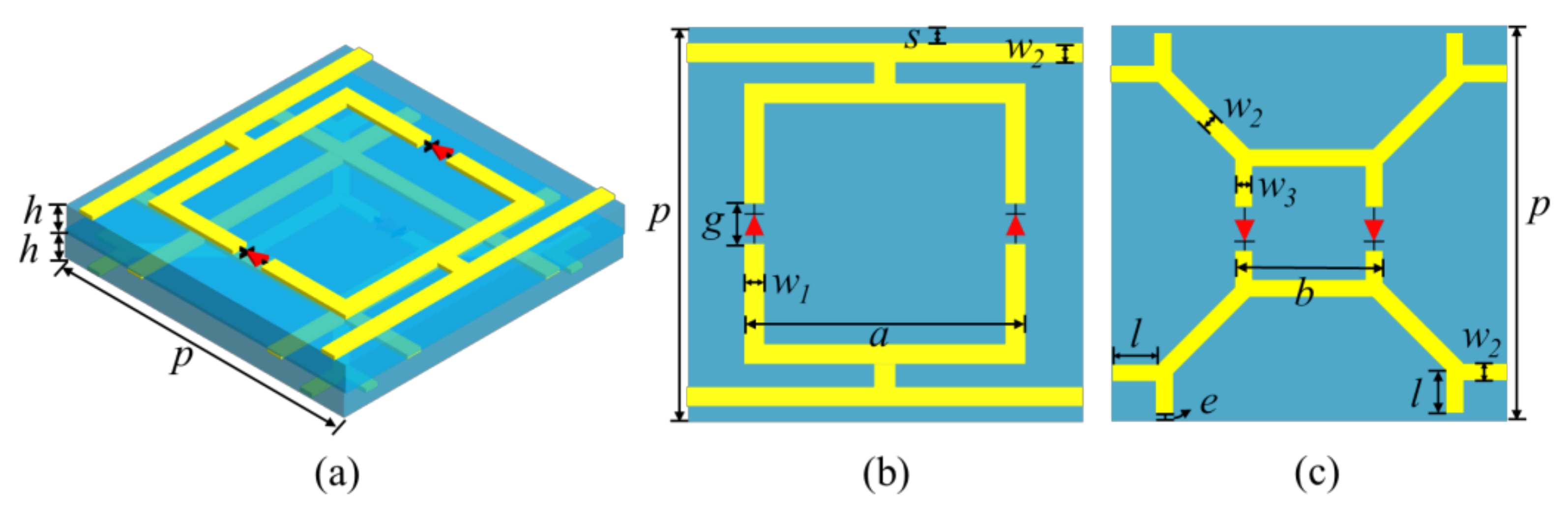
3. Design and Analysis of the Meta-Device

As shown in Figure 2, the proposed meta-atom is composed of three metallic layers with two thin substrates in between. The substrate used is F4B. Its relative permittivity and loss tangent angle are 2.65 and 0.001, respectively. The larger and smaller split square rings are placed on the top and bottom layers, respectively. The structure of the middle layer is a metal grid, which is equated to the inductance Lm. It is mutually coupled with the metallic structures on the top and bottom layers and form two parallel L-C resonances. Therefore, the structure of dual-transmission windows is constructed. Varactor diodes are mounted on the top and bottom layers. Due to the bias network design, the dual-transmission windows are independently regulated by tuning varactor diodes. The geometric parameters are fixed as: the periodical length is p = 15 mm, the outside lengths of the split square ring on the top and bottom layer are a = 12 mm and b = 5.4 mm, the widths of thin metal lines are w1 = 0.3 mm, w2 = 0.2 mm, and w3 = 0.3 mm, the thickness of the substrate h = 0.6 mm, the branch length on the bottom layer l = 1 mm, the space for mounting varactor diodes is g = 1 mm, the widths between two adjacent unit cells on the top and bottom layer are s = 0.3 mm and e = 0.1 mm.
The performance of the designed meta-device is analyzed with the commercial electromagnetic simulation software of CST Microwave Studio. The boundaries were set to unit cell in the x and y directions, open (add space) in the z direction, the frequency-domain solver is chosen to perform the operation. The transmission spectra of the meta-device are plotted in Figure 3.
Cv1 and Cv2 are capacitances of varactor diodes on the top and bottom layer. When the Cv1, Cv2 of varactor diodes are 0.35 pF and 0.466 pF, the two resonant frequencies (f1, f2) of this meta-device are 2.72 GHz and 4.83 GHz. The corresponding insertion losses are 0.50 dB and 1.54 dB, respectively. The resonance frequency f1 moves to low frequency from 2.72 GHz to 2.20 GHz when the value of Cv1 alters from 0.35 pF to 3.2 pF and the value of Cv2 is 0.466 pF. The insertion losses are from 0.50 dB to 0.96 dB. When the value of Cv2 changes from 0.466 pF to 2.35 pF and the value of Cv1 is 0.35 pF, the resonance frequency f2 moves to low frequency from 4.83 GHz to 4.27 GHz with the insertion losses from 1.54 dB to 2.28 dB. It can be clearly seen that the resonance frequencies (f1, f2) keep shifting when the capacitance values (Cv1, Cv2) of the varactor diodes increase. The varactor diodes can cause red shifts of the resonant frequencies (f1, f2).
As shown in Figure 4, the ECM of the proposed meta-atom is obtained. On the top layer, Ct1 and Ct2 represent the gap capacitances that are resulted from the couplings of square ring, bias line, and adjacent cells. Lt1 and Lt2 are the equivalent inductances of the metal strip and split square ring. The metal grid of the middle layer is equated to the inductance Lm. The gap capacitance Cb of adjacent cells and the equivalent inductance Lb of the metal strip constitute the ECM of the metal pattern on the bottom layer. In addition, Cv1 and Cv2 are capacitances of varactor diodes on the top and bottom layer. The top metal structure and the metal grid form a parallel L-C resonance (f1). The metal structures on the bottom layer and the metal grid constitute another parallel L-C resonance (f2). Based on the proposed ECM in Figure 4, the resonant frequencies (f1, f2) are:
f 1 = 1 2 π C t 1 + C t 2 + C v 1 L t 1 + L t 2 + L m ,
f 2 = 1 2 π C b + C v 2 L b + L m .
In order to further demonstrate the principle of the proposed structure, the parametric analysis is discussed and summarized in Figure 5. “a” and “b” are the widths of the split square rings on the top and bottom layers, respectively. They affect the corresponding series L-C resonance in the equivalent circuit. As shown in Figure 5a,d, the corresponding series resonant frequency shift toward higher frequency as they increase. The widths (“s”) between two adjacent unit cells on the top layer affect both the series and parallel resonant frequencies of the corresponding layer in Figure 5b. The metal grid of the middle layer is essential to form the two transmission windows. It can be clearly seen from Figure 5c that as the width of the metal (“w”) increases, the two resonant frequencies move simultaneously to high frequencies. In addition, the thickness of the substrate (“h”) has no significant effect on the resonant frequency in Figure 5e. However, it has an attenuating effect on the transmission coefficient. This is determined by the specific impedance of the substrate used. Therefore, the thick substrate is not suitable for the proposed structure.
When the EM wave illuminate obliquely, the equivalent capacitance and inductance corresponding to metal structures change. This leads to blue shifts of the resonant frequencies (f1, f2). By adjusting the equivalent capacitances (Cv1, Cv2) of varactor diodes, the overall impedance of the ECM is equal to that under normal incidence. The angular dispersion can be compensated in this active method. However, the compensation range of angular dispersion is limited due to the variable capacitance and cut-off voltage of the varactor diodes used. Here, transmission characteristics with incidence angles from 0° to 60° are investigated and analyzed. The resonance frequency f1 moves to a high frequency (from 2.72 GHz to 3.19 GHz) and the CST simulation results are depicted in Figure 6a. The insertion losses are from 0.50 dB to 0.96 dB. Additionally, the resonance frequency f2 moves to high frequency from 2.72 GHz to 3.19 GHz with the insertion loss from 1.54 dB to 2.25 dB. Obviously, the effect of angular dispersion becomes intense as the angle of incidence increases. The angular dispersion leads to blue shifts of dual-transmission windows. The blue shifts of angular dispersion and the red shifts introduced by the varactor diodes are in reverse trend. Therefore, the angular dispersion can be compensated by tuning varactor diodes.
Then, the capacitance (Cv1, Cv2) of varactor diodes is adjusted to compensate the angular dispersion with the incident angle from 0° to 60°. The simulated results for tunable angular dispersion are shown in Figure 6b. When Cv1 and Cv2 are 0.35 pF and 0.466 pF, the resonance frequencies are 2.72 GHz and 4.83 GHz at vertical incidence. As the incident angle changes to 15°, the resonance frequency f1 shift to 2.76 GHz. Then, it can remain at 2.72 GHz to tune Cv1 at 0.37 pF. The resonance frequency f1 shift to 2.85 GHz when the incident angle is 30°, which can be converted to 2.72 GHz by changing Cv1 at 0.47 pF. At the incidence angle of 45°, the resonance frequency f1 is 3.01 GHz. In order to remain at 2.72 GHz, the capacitance of Cv1 is varied to 0.76 pF. When the incident angle is 60°, the resonance frequency f1 shift to 3.19 GHz. Then it can be compensated at 2.72 GHz by tuning Cv1 at 2.50 pF. In conclusion, the resonance frequency f1 of the transmission window at 2.72 GHz can be stable by tuning Cv1 when the incidence angle alters from 0° to 60°.
It is also revealed from Figure 6b that the resonance frequency f2 can remain at 4.83 GHz as the incidence angle changes from 0° to 60°. When the incident angle is 15° and 30°, both the resonance frequency f2 are 4.83 GHz with Cv2 of 0.48 pF and 0.54 pF, respectively. However, the capacitance Cv2 of the varactor diode is, respectively, altered to 0.64 pF and 0.9 pF to compensate angular dispersion at 4.83 GHz when the incidence angle is 45° and 60°. The variable capacitances (Cv1, Cv2) of varactor diodes to eliminate the angular dispersion with the incident angle from 0° to 60° are shown in Table 1. The above simulation results demonstrate that the blue shifts of angular dispersion can be dynamically compensated by the red shifts introduced by the varactor diodes with the incident angle from 0° to 60°.

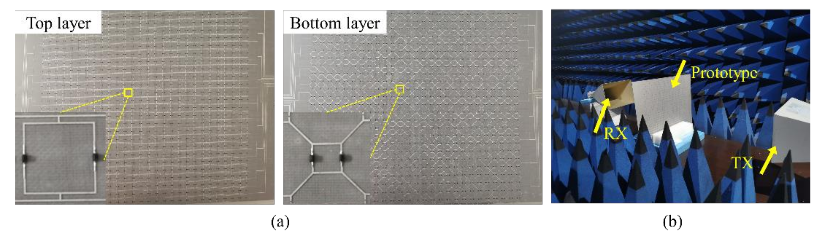
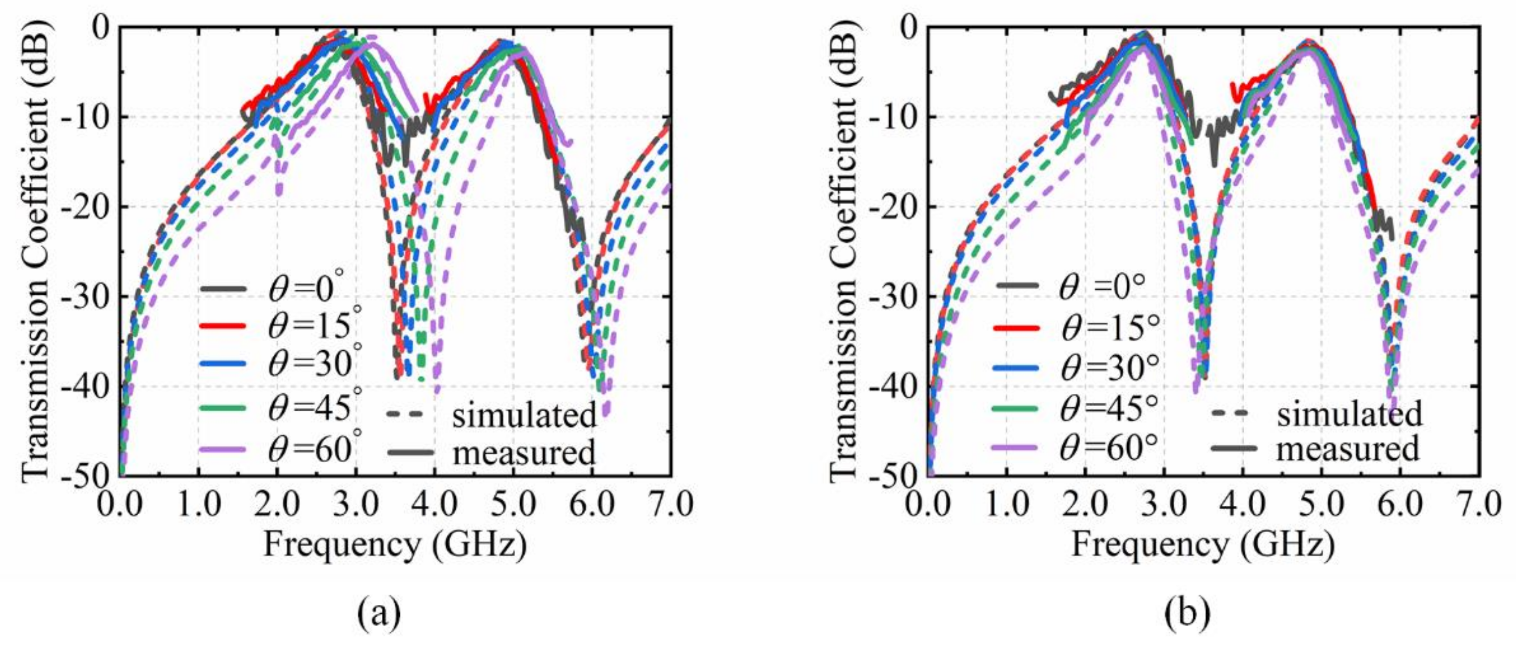
4. Experimental Verification

A prototype of the proposed meta-device has been fabricated and measured in an anechoic chamber to verify the feasibility of this dynamic modulation method. It has 2916 varactor diodes and 27 × 27 structural cells. Including external bias network, the whole sample size is 525 mm × 525 mm. The substrates used are two 0.6 mm thick F4B. The relative permittivity and loss tangent angles are 2.65 and 0.001, respectively. The surface appearance of the prototype is shown in Figure 7a. The varactor diodes SMV2020-079LF and SMV1231-079LF are embedded in the split square rings on the top and bottom layer, respectively. They are mounted in the same direction. The specific test environment is shown in Figure 7b. Two horn antennas are used to transmit and receive EM waves. The network analyzer used is the Agilent N5224A vector network analyzer. Two DC voltage sources are connected to the top and bottom layers of the prototype to drive the varactor diodes.
The measured results are shown in Figure 8 and Figure 9. It is clearly revealed from Figure 8 that the varactor diodes on the top and bottom layer can regulate the shifts of the dual-transmission windows independently. When Cv1 changes from 0.35 pF to 3.20 pF and Cv2 is kept at 0.466 pF, the resonance frequency f1 moves from 2.74 GHz to 2.21 GHz, and the resonance frequency f2 approximately remains at 4.85 GHz. Conversely, when Cv2 varies and Cv1 is constant, the resonance frequency f2 changes from 4.85 GHz to 4.30 GHz and the resonance frequency f1 approximately remains at 2.74 GHz.
The excellent performance of the tunable angular dispersion is also demonstrated in Figure 9. In Figure 9a, with the capacitance Cv1 of 0.35 pF and Cv2 of 0.466 pF, the resonance frequency f1 shifts from 2.74 GHz to 3.19 GHz and the resonance frequency f2 shifts from 4.85 GHz to 5.12 GHz when the incidence angle from 0° to 60°. According to the shifting trend of the resonance frequencies, the angular dispersion can be adjusted by tuning Cv1 and Cv2 simultaneously, which is depicted in Figure 9b. The equivalent capacitance (Cv1, Cv2) of the varactor diodes and the external DC voltages (U1, U2) are shown in Table 2. The capacitance values Cv1 on the top layer are tuned to 0.37 pF, 0.47 pF, 0.76 pF and 2.50 pF at incident angle of 15°, 30°, 45°, and 60°, in which the external DC voltages U1 are at 15.1 V,12.1 V, 7.5 V, and 0.8 V. The resonance frequency f1 approximately remains at 2.73 GHz from 0° to 60°. At the same time, the capacitance Cv2 also need tune at 15°, 30°, 45°, and 60°, which are 0.48 pF, 0.54 pF, 0.64 pF, and 0.90 pF with relative to 9.4 V, 7.9 V, 6.2 V, and 3.5 V of the DC voltages U2. All of these experimental results agree reasonably well with the simulations. However, due to the measured environment and manufacturing uncertainty, there are still some deviations in the measuring results. The parameters of the varactor diodes are not constant such as in the datasheet in the actual measurement, which also interferes with the test results. In addition, there are some undulations in measurement results. The output of the signal transmitter through the power amplifier is not stable. The free-space method itself has this limitation. The wave generated from the transmitting horn is also not strictly planar. This can also produce fluctuations in the test results.
The performance comparison of the meta-devices with dual transmission windows is shown in Table 3. Passive meta-devices can only weaken the effect of angular dispersion from their structure. They are still limited by the angular range and angular dispersion. The active meta-device can shift the resonant frequency of the transmission window by introducing active components. However, the angular dispersion still has an impact on the EM performance as the incident angle increases. The proposed method for compensating angular dispersion generates a red shift by adjusting the varactor diodes. At oblique incidence, the red shift is compensated with the blue shift of the angular dispersion. Thus, the proposed meta-device achieves the characteristic of tunable angular dispersion. This advancement makes it have great application prospect in angle-multiplexed communications, and incident-angle-insensitive equipment.

5. Conclusions

In this paper, a paradigm for tunable angular dispersion with the varactor diodes is proposed. The main conclusions of this article are as follows:
(1)
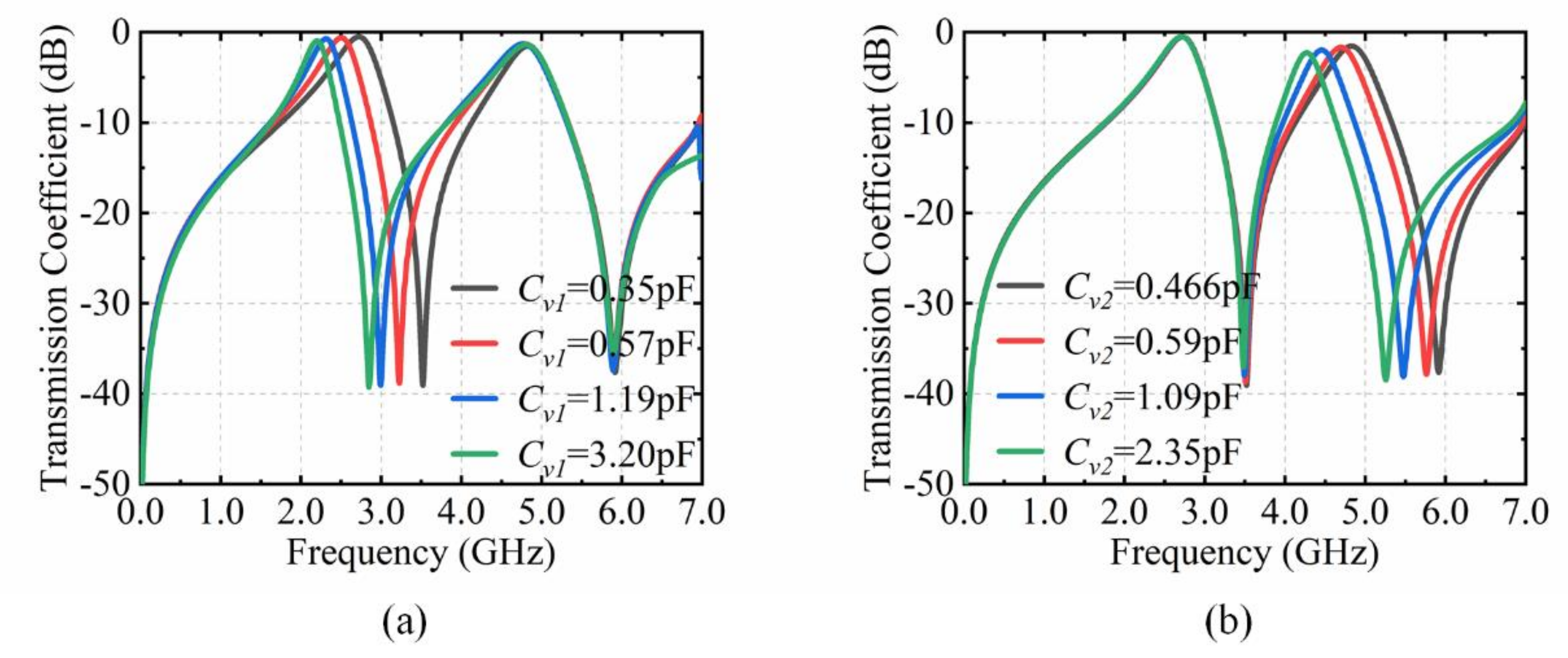
A method to dynamically modulate the angular dispersion is proposed and validated. The varactor diode can continuously modulate the resonant frequency of the transmission window. Thus, the angular dispersion can be dynamically compensated by mounting the varactor diode in the passive meta-atom.
(2)
The modulation method is applied to meta-devices with dual-transmission windows. Based on the analysis of the equivalent circuit model, the overall impedance of the structure is maintained constant by modulating the varactor diode. Thus, the blue shift of the angular dispersion and the red shift introduced by the varactor diode counteract each other to achieve angular dispersion compensation.
(3)
As a proof-of-principle, a triple-layer meta-device with dual-transmission windows is designed and analyzed. The dual-transmission windows are, respectively, adjusted by varactor diodes on the top and bottom layer. With CST simulation and measurement, it can achieve the angular dispersion compensation at 2.72 GHz and 4.83 GHz as the incidence angle changes from 0° to 60°.
Therefore, the proposed meta-device provides a method for tunable angular dispersion based on active components, which has applications in angle-multiplexed communications, and incident-angle-insensitive equipment. In addition, it still has great prospects for applications in terahertz and other optical fields.

Author Contributions

Conceptualization, M.Y.; methodology, H.B.; software, C.L.; validation, H.B.; formal analysis, C.L.; investigation, W.W.; resources, H.B.; data curation, H.B.; writing—original draft preparation, C.L.; writing—review and editing, H.W.; visualization, Z.L.; supervision, M.Y.; project administration, J.W.; funding acquisition, S.Q. All authors have read and agreed to the published version of the manuscript.

Funding

This research was funded by National Natural Science Foundation of China under Grant Nos. 61971435, 61971437; National Key Research and Development Program China under Grant No. 2017YFA0700201. Natural Science Foundation of Shaanxi Province under Grant No. 2020JM-342, 2022JM-352, 2022JQ-630.

Institutional Review Board Statement

Not applicable.

Informed Consent Statement

Not applicable.

Data Availability Statement

Not applicable.

Conflicts of Interest

The authors declare no conflict of interest.

References

  1. Pattanayak, A.; Rana, G.; Jain, R.; Bhattacharya, A.; Duttagupta, S.P.; Gandhi, P.S.; Achanta, V.G.; Prabhu, S.S. Resonant THz transmission through asymmetric aperture array with polarization controlled resonant peaks and Q-factors. J. Appl. Phys. 2019, 126, 223103. [Google Scholar] [CrossRef]
  2. Yuan, Q.; Meng, Y.; Li, Y.; Wang, H.; Cheng, Y.; Ma, H.; Liu, T.; Wang, J.; Qu, S. Full-polarization frequency controlled multi-mode spoof surface plasmon polaritons excitation via anisotropic meta-structure. Adv. Opt. Mater. 2022, 10, 2101369. [Google Scholar] [CrossRef]
  3. Noroozi, R.; Bodaghi, M.; Jafari, H.; Zolfagharian, A.; Fotouhi, M. Shape-adaptive metastructures with variable bandgap regions by 4D printing. Polymers 2020, 12, 519. [Google Scholar] [CrossRef] [PubMed] [Green Version]
  4. Devlin, R.C.; Ambrosio, A.; Rubin, N.A.; Mueller, J.P.B.; Capasso, F. Arbitrary spin-to–orbital angular momentum conversion of light. Science 2017, 358, 896–901. [Google Scholar] [CrossRef] [PubMed] [Green Version]
  5. Ding, G.; Chen, K.; Luo, X.; Zhao, J.; Jiang, T.; Feng, Y. Dual-helicity decoupled coding metasurface for independent spin-to-orbital angular momentum conversion. Phys. Rev. Appl. 2019, 11, 044043. [Google Scholar] [CrossRef]
  6. Sun, S.; Yang, K.Y.; Wang, C.M.; Juan, T.K.; Chen, W.T.; Liao, C.Y.; He, Q.; Xiao, S.; Kung, W.T.; Guo, G.Y.; et al. High-efficiency broadband anomalous reflection by gradient meta-surfaces. Nano Lett. 2012, 12, 6223–6229. [Google Scholar] [CrossRef]
  7. Yu, N.; Genevet, P.; Kats, M.A.; Aieta, F.; Tetienne, J.; Capasso, F.; Gaburro, Z. Light propagation with phase discontinuities: Generalized laws of reflection and refraction. Science 2011, 334, 333–337. [Google Scholar] [CrossRef] [Green Version]
  8. Ni, X.; Wong, Z.J.; Mrejen, M.; Wang, Y.; Zhang, X. An ultrathin invisibility skin cloak for visible light. Science 2015, 349, 1310–1314. [Google Scholar] [CrossRef]
  9. Yu, N.; Genevet, P.; Kats, M.A.; Aieta, F.; Tetienne, J.P.; Capasso, F.; Gaburro, Z. Flat optics: Controlling wavefronts with optical antenna metasurfaces. IEEE J. Sel. Top. Quant. 2013, 19, 4700423. [Google Scholar]
  10. Yan, L.; Zhu, W.; Karim, M.F.; Cai, H.; Gu, A.Y.; Shen, Z.; Chong, P.H.J.; Tsai, D.P.; Kwong, D.L.; Qiu, C.W.; et al. Arbitrary and independent polarization control in situ via a single metasurface. Adv. Opt. Mater. 2018, 6, 1800728. [Google Scholar] [CrossRef]
  11. Huang, C.; Zhang, C.L.; Yang, J.; Sun, B.; Zhao, B.; Luo, X.G. Reconfigurable metasurface for multifunctional control of electromagnetic waves. Adv. Opt. Mater. 2017, 5, 1700485. [Google Scholar] [CrossRef]
  12. Tao, Z.; Wan, X.; Pan, B.C.; Cui, T.J. Reconfigurable conversions of reflection, transmission, and polarization states using active meta-surface. Appl. Phys. Lett. 2017, 110, 121901. [Google Scholar] [CrossRef]
  13. Luo, Z.J.; Wang, Q.; Zhang, X.G.; Wu, J.W.; Dai, J.Y.; Zhang, L.; Wu, H.T.; Zhang, H.C.; Ma, H.F.; Cheng, Q.; et al. Intensity-dependent metasurface with digitally reconfigurable distribution of nonlinearity. Adv. Opt. Mater. 2019, 7, 1900792. [Google Scholar] [CrossRef]
  14. Dai, J.Y.; Zhao, J.; Cheng, Q.; Cui, T.J. Independent control of harmonic amplitudes and phases via a time-domain digital coding metasurface. Light Sci. Appl. 2018, 7, 90. [Google Scholar] [CrossRef]
  15. Shang, G.; Wang, Z.; Li, H.; Zhang, K.; Wu, Q.; Burokur, S.N.; Ding, X. Metasurface holography in the microwave regime. Photonics 2022, 8, 135. [Google Scholar] [CrossRef]
  16. Chong, K.E.; Wang, L.; Staude, I.; James, A.R.; Dominguez, J.; Liu, S.; Subramania, G.S.; Decker, M.; Neshev, D.N.; Brener, I.; et al. Efficient polarization-insensitive complex wavefront control using Huygens’ metasurfaces based on dielectric resonant meta-atoms. ACS Photonics 2016, 3, 514–519. [Google Scholar] [CrossRef]
  17. Aieta, F.; Kats, M.A.; Genevet, P.; Capasso, F. Multi-wavelength achromatic metasurfaces by dispersive phase compensation. Science 2015, 347, 1342–1345. [Google Scholar] [CrossRef]
  18. Huang, Y.; Zhao, Q.; Kalyoncu, S.K.; Torun, R.; Lu, Y.; Capolino, F.; Boyraz, O. Phase-gradient gap-plasmon metasurface based blazed grating for real time dispersive imaging. Appl. Phys. Lett. 2014, 104, 161106. [Google Scholar] [CrossRef] [Green Version]
  19. Cui, T.J.; Qi, M.Q.; Wan, X.; Zhao, J.; Cheng, Q. Coding metamaterials, digital metamaterials and programmable metamaterials. Light Sci. Appl. 2014, 3, e218. [Google Scholar] [CrossRef]
  20. Huang, C.; Sun, B.; Pan, W.; Cui, J.; Wu, X.; Luo, X. Dynamical beam manipulation based on 2-bit digitally-controlled coding metasurface. Sci. Rep. 2017, 7, 42302. [Google Scholar] [CrossRef] [Green Version]
  21. Li, L.; Cui, T.J.; Ji, W.; Liu, S.; Ding, J.; Wan, X.; Li, Y.B.; Jiang, M.; Qiu, C.W.; Zhang, S. Electromagnetic reprogrammable coding-metasurface holograms. Nat. Commun. 2017, 8, 197. [Google Scholar] [CrossRef] [Green Version]
  22. Ma, Q.; Shi, C.B.; Bai, G.D.; Chen, T.Y.; Noor, A.; Cui, T.J. Beam-editing coding metasurfaces based on polarization bit and orbital-angular-momentum-mode bit. Adv. Opt. Mater. 2017, 5, 1700548. [Google Scholar] [CrossRef]
  23. Deng, Z.; Deng, J.; Zhuang, X.; Wang, S.; Li, K.; Wang, Y.; Chi, Y.; Ye, X.; Xu, J.; Wang, G.P.; et al. Diatomic metasurface for vectorial holography. Nano Lett. 2018, 18, 2885–2892. [Google Scholar] [CrossRef]
  24. Deng, Z.; Deng, J.; Zhuang, X.; Wang, S.; Shi, T.; Wang, G.P.; Wang, Y.; Xu, J.; Cao, Y.; Wang, X.; et al. Facile metagrating holograms with broadband and extreme angle tolerance. Light Sci. Appl. 2018, 7, 78. [Google Scholar] [CrossRef] [Green Version]
  25. Bao, Y.; Yu, Y.; Xu, H.; Lin, Q.; Wang, Y.; Li, J.; Zhou, Z.; Wang, X. Coherent Pixel Design of Metasurfaces for Multidimensional Optical Control of Multiple Printing-Image Switching and Encoding. Adv. Funct. Mater. 2018, 28, 1805306. [Google Scholar] [CrossRef]
  26. Leitis, A.; Tittl, A.; Liu, M.; Lee, B.H.; Gu, M.B.; Kivshar, Y.S.; Altug, H. Angle-multiplexed all-dielectric metasurfaces for broadband molecular fingerprint retrieval. Sci. Adv. 2019, 5, eaaw2871. [Google Scholar] [CrossRef] [Green Version]
  27. Deng, Z.L.; Cao, Y.; Li, X.; Wang, G.P. Multifunctional metasurface: From extraordinary optical transmission to extraordinary optical diffraction in a single structure. Photonics Res. 2018, 6, 443–450. [Google Scholar] [CrossRef]
  28. Qiu, M.; Jia, M.; Ma, S.; Sun, S.; He, Q.; Zhou, L. Angular dispersions in terahertz metasurfaces: Physics and applications. Phys. Rev. Appl. 2018, 9, 054050. [Google Scholar] [CrossRef]
  29. Marcuvitz, N. Waveguide Handbook (No. 21); IET: London, UK, 1951. [Google Scholar]
  30. Li, Y.; Ren, P.; Xiang, Z. A dual-passband frequency selective surface for 5G communication. IEEE Antenn. Wirel. Pr. 2019, 18, 2597–2601. [Google Scholar] [CrossRef]
  31. Yadav, S.; Jain, C.P.; Sharma, M.M. Polarization independent dual-bandpass frequency selective surface for Wi-max applications. Int. J. RF Microw. Comput. Aided Eng. 2018, 28, e21278. [Google Scholar] [CrossRef]
  32. Rahmani-Shams, Y.; Mohammd-Ali-Nezhad, S.; Yeganeh, A.N.; Sedighy, S.H. Dual band, low profile and compact tunable frequency selective surface with wide tuning range. J. Appl. Phys. 2018, 123, 235301. [Google Scholar] [CrossRef]
  33. Ghosh, S.; Srivastava, K.V. A dual-band tunable frequency selective surface with independent wideband tuning. IEEE Antenn. Wirel. Propag. Lett. 2020, 19, 1808–1812. [Google Scholar] [CrossRef]
Figure 1. The diagram of the path of action of EM waves and the corresponding equivalent circuit model.
Materials 15 03686 g001
Figure 2. Geometry of the proposed meta-atom. (a) 3-D view of the structure. (b) The top layer. (c) The bottom layer.
Materials 15 03686 g002
Figure 3. CST simulation results of the proposed structure. (a) Transmission coefficient with Cv1 from 0.35 pF to 3.20 pF. (b) Transmission coefficients with Cv2 from 0.466 pF to 2.35 pF.
Materials 15 03686 g003
Figure 4. Simplified ECM of the meta-device.
Materials 15 03686 g004
Figure 5. Parametric analysis by CST simulation. (a) The outside lengths of the split square ring on the top layer. (b) The width between two adjacent unit cells on the top layer. (c) The width of the metal grid on the middle layer. (d) The outside lengths of the split square ring on the bottom layer. (e) The thickness of the substrate.
Materials 15 03686 g005
Figure 6. CST simulation results of the proposed structure. (a) Transmission coefficient with incidence angles from 0° to 60°. (b) The effect of angular dispersion compensation with incidence angles from 0° to 60°.
Materials 15 03686 g006
Figure 7. (a) The surface appearance of the prototype. (b) The specific test environment.
Materials 15 03686 g007
Figure 8. Comparison of measurement results and simulation. (a) Transmission coefficient with Cv1 from 0.35 pF to 3.20 pF. (b) Transmission coefficient with Cv2 from 0.466 pF to 2.35 pF.
Materials 15 03686 g008
Figure 9. Comparison of measurement results and simulation. (a) Transmission coefficient with the incident angle from 0° to 60°. (b) Transmission coefficient for angular dispersion compensation by tuning Cv1 and Cv2.
Materials 15 03686 g009
Table 1. The variable capacitance of varactor diodes with the incident angle from 0° to 60°.
The Incident Angle (°)The Variable Capacitance of the Varactor Diode (pF)
The Top Layer Cv1The Bottom Layer Cv2
00.350.466
150.370.48
300.470.54
450.760.64
602.500.90
Table 2. The measurement parameters for achieving angular non-dispersion.
The Incident Angle (°)The Capacitance Cv1 (pF)DC Voltage U1 (V)The Capacitance Cv2 (pF)DC Voltage U2 (V)
00.3516.20.46610.2
150.3715.10.489.4
300.4712.10.547.9
450.767.50.646.2
602.500.80.903.5
Table 3. Comparison with the meta-devices for dual-transmission windows.
ReferenceTypeDual-Transmission Windows (GHz)Angular StabilityAngular Dispersion
[30]passive27.7/39.145°2.3%
[31]passive2.5/5.545°Not stated
[32]active2.28–4.66/5.44–11.360°Not stated
[33]active0.28–1.28/0.52–1.9860°Not stated
Proposed paperactive2.74/4.8560°tunable
Publisher’s Note: MDPI stays neutral with regard to jurisdictional claims in published maps and institutional affiliations.

