Article

Electrochemical Corrosion Behavior of MIG-Welded 7N01-T4 Aluminum Alloy by ER5356 and ER5087 Welding Wires

1
School of Material Science and Engineering, Jiangsu University of Science and Technology, Zhenjiang 212003, China
2
School of Material Science and Engineering, Hefei University of Technology, Hefei 230009, China
*
Author to whom correspondence should be addressed.
Submission received: 23 March 2022 / Revised: 7 May 2022 / Accepted: 18 May 2022 / Published: 23 May 2022
(This article belongs to the Topic Advanced Forming Technology of Metallic Materials)

Abstract

:
7N01-T4 aluminum alloy plates were welded by the metal inert gas (MIG) welding method, with ER5087 and ER5356 welding wires, respectively. The electrochemical corrosion behavior of the weld zones in the two kinds of welded joints using 3.5 wt.% and 5 wt.% NaCl solutions were investigated by polarization curve, electrochemical impedance spectroscopy (EIS), scanning electron microscope (SEM), and laser confocal scanning microscope (LCSM). The results indicated the better corrosion resistance of the weld zone in the ER5356 welded joint than that in the ER5087 welded joint, which was related to the different contents of Mn and Zn elements and the distribution of precipitates for the weld zones in the two kinds of welded joints. Based on the LSCM of the weld zones, the maximum depth (dmax) of corrosion pits for the weld zone in the ER5356 welded joint was lower than that in the ER5087 welded joint when immersed in the same NaCl concentrations. The dmax of the corrosion pit of the weld zone in the ER5356 welded joint using the 5 wt.% NaCl solution was 78.5 ± 0.96 μm, which was much bigger than that using the 3.5 wt.% NaCl solution. For the weld zone in the ER5087 welded joint with 5 wt.% NaCl solution, more Cl- was adsorbed onto the active surface of weld zones, which accelerated the corrosion, resulting in the corrosion mechanism from pitting to intergranular corrosion.

1. Introduction

The Al-Zn-Mg alloy has seen wide acceptance in the manufacturing field of high-strength and lightweight structures, such as high-speed trains, marine ships, aerospace, and other fields. As a typical Al-Zn-Mg alloy, 7N01 aluminum alloy has excellent extrusion property and good welding performance as an ideal lightweight material widely used in the body structure of high-speed trains [1,2,3].
Welding wire is a critical factor affecting the composition, microstructure, hot crack resistance of weld metal and base metal near the weld, corrosion resistance, and mechanical properties of welded joints. The common filler wires for 7N01 aluminum alloy welding mainly include ER5356 (Al-Mg) and ER5087 (Al-Mg) welding wires. Al-Mg welding wire increases the content of magnesium in the weld and forms strengthening phase Al8Mg5 [4,5]. In comparison with ER5356 welding wire, ER5087 welding wire contains trace Zr and more Mn elements. Zr and Al peritectic reaction occurs to form dispersed and coherent with the matrix Al3Zr, which provides the basis for heterogeneous nucleation to promote the formation of fine equiaxed crystals, so as to improve the strength of weld metal [6,7]. Some researchers have studied the influence of ER5356 and ER5087 welding wires on the microstructure and mechanical properties of 7N01 aluminum alloy welded joints. Xie et al. [8] found that the tensile strength and elongation of the ER5087 welded joint were greater than those of the ER5356 welded joint. This is attributed to refining the structure by adding Zr element to the formation of Al3Zr. Liu et al. [9] found the porosity and the eutectic melting in the heat affected zone led to crack initiation for ER5087 and ER5356 welded joints during the fatigue process, respectively. However, there are few reports comparing the effect of ER5356 and ER5087 welding wires on the corrosion properties of 7N01 aluminum alloy joint. A 7N01 aluminum alloy welded joint experienced the rapid hot and cold process, the local microstructure changed complex, the precipitated phase produced unbalanced dissolution and precipitation behavior, and redistributed in the boundary and grain boundary, resulting in the non-uniformity structure of a welded joint. Thus, the corrosion resistance decreased [10,11]. Moreover, 7N01 aluminum alloy has corrosion sensitivity in humid and chlorine environments [12,13,14]. Long term exposure of the 7N01 aluminum alloy body of a high-speed train to atmospheric environment and polluted anions in urban and coastal areas will cause corrosion damage, leading to deterioration of the structure and performance. So, it is of practical significance to study the corrosion behavior of 7N01 aluminum alloy welded joints to ensure the safe operation of high-speed trains.
In this paper, 7N01-T4 aluminum alloy was MIG welded with ER5087 and ER5356 welding wires, respectively. Electrochemical methods were used to study the corrosion behavior of the weld zones of ER5356 and ER5087 welded joints in 3.5 wt.% and 5 wt.% NaCl solutions, respectively. The morphology and the dmax of corrosion pit of the weld zones observation were investigated.

2. Experimental Procedure

2.1. Experimental Materials

7N01-T4 aluminum alloys were used as the base materials in the form of 12 mm thick plates. The filling wires were ER5087 and ER5356 alloy with a diameter of 1.6 mm. The chemical compositions of 7N01-T4 aluminum alloy, ER5356 and ER5087 welding wires used in the experiment are listed in Table 1.

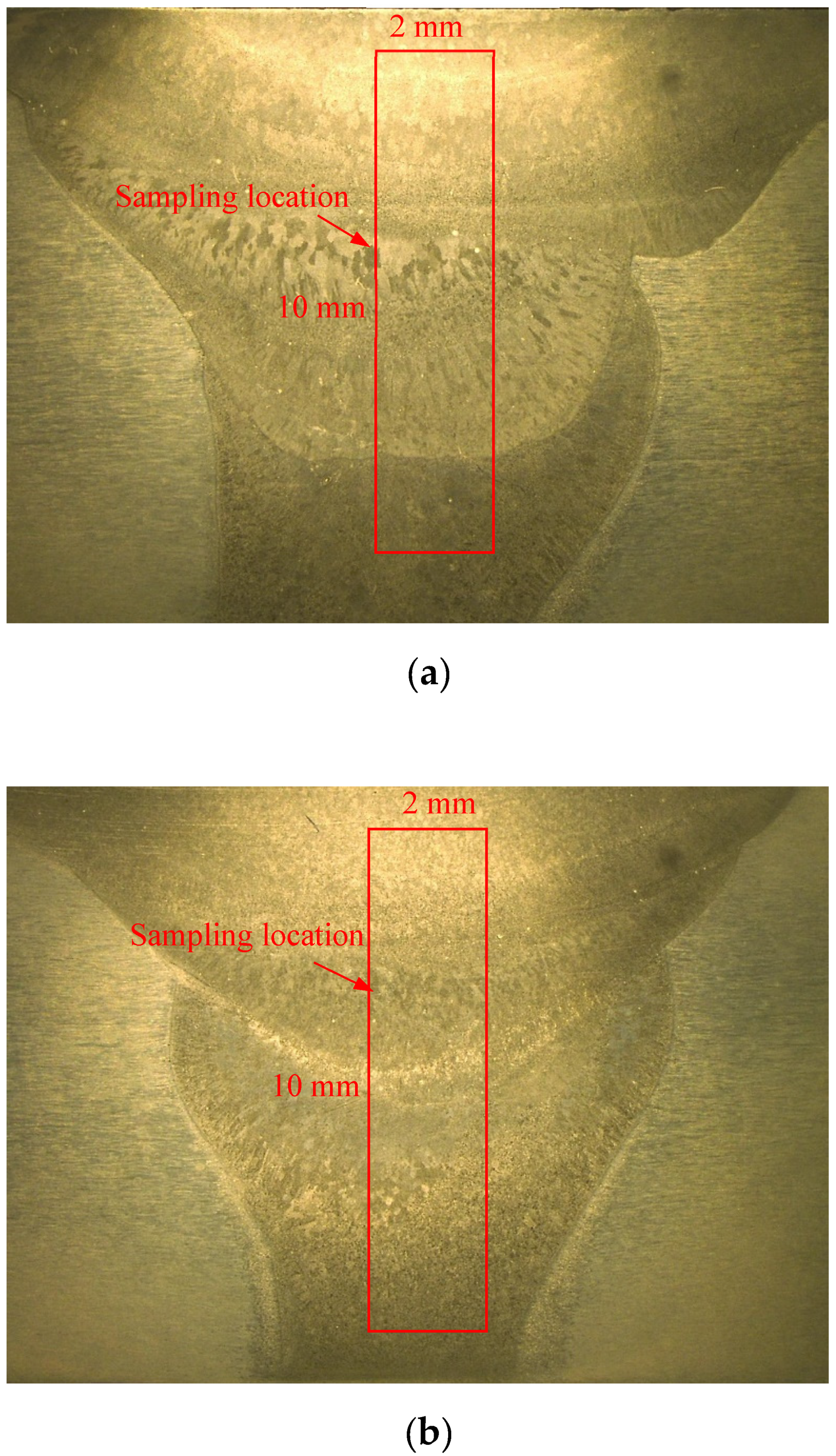
2.2. Welding Process

The 7N01-T4 aluminum alloy was butt joined using MIG welding. High-purity argon gas (99.999%) was used as the shield gas. A “V-shape” groove was made by an angle of 70°, and the root face was 2 mm. The welding direction was perpendicular to the rolling direction. The welding process was divided into three passes. The welding process parameters are given in Table 2.

2.3. Electrochemical Corrosion Test and Microstructural Observation

Figure 1 shows the sampling location in ER5087 and ER5356 welded joints for the electrochemical corrosion test. Electrochemical experiments of the two kinds of weld zones were carried out on Coster CH350S electrochemical workstation in 3.5 wt.% and 5 wt.% NaCl solutions, respectively.
Table 3 shows the abbreviation of samples. Three electrode system devices were used in the test. A saturated calomel electrode (SCE) was adopted as the reference electrode. Pt sheet was used as the auxiliary electrode and 1 cm2 electrode area was served as the working electrode. The samples were immersed in the NaCl solutions for 1 h before testing the open circuit potential (OCP). The measurement time of the OCP was 20 min to make the electrode system reach a stable state. The electrochemical impedance test frequency ranged from 105 to 10−2 Hz, and the amplitude of AC signal imposed was 10 mV. Zview software was used to analysis the EIS measurements. The experiment of potentiodynamic polarization was performed after the EIS test. The scanning range of the potential was ±50 mV (relative to the OCP) with a scan rat 0.5 mV/s. The corrosion potential (Ecorr) and corrosion current density (Icorr) were obtained by Tafel-type fit from the polarization curves. All electrochemical measurements were repeated three times to ensure the accuracy of test results.
The micromorphology was observed by SEM (JSM-6480). The energy disperse spectroscopy (EDS) in SEM was used to analyze the chemical composition. The depth of corrosion pit was determined by LCSM (LEXT OLS4000).

3. Results and Discussion
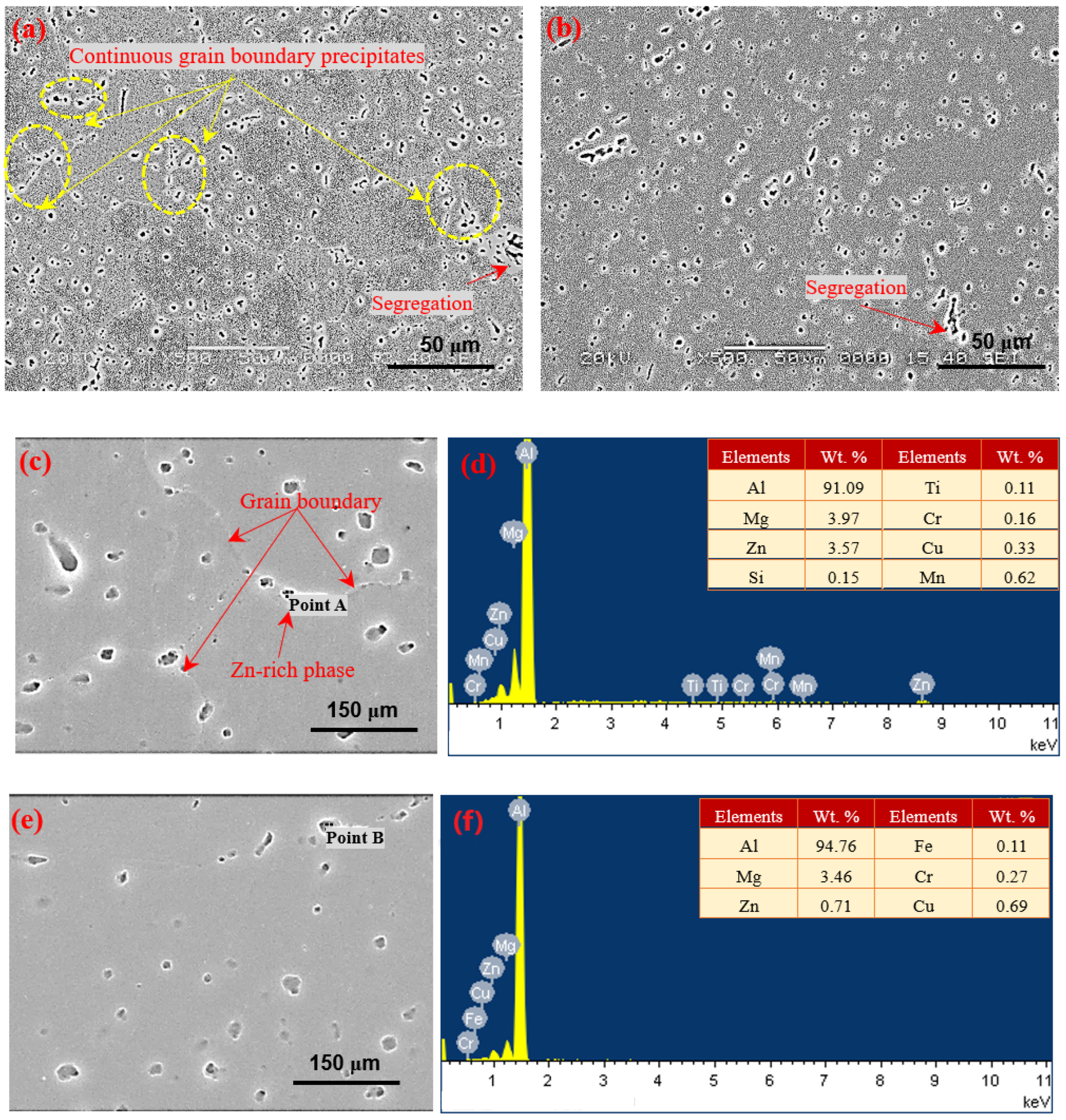
3.1. Microstructure

Figure 2 shows SEM and EDS for two kinds of weld zones before electrochemical corrosion. The precipitates were distributed in a continuous network on the grain boundary, and segregation along grain boundaries also existed in the weld zone of the ER5087 welded joint shown in Figure 2a, while the precipitates and segregation were mainly dispersed in the weld zone of the ER5356 welded joint in Figure 2b. In order to further determine the composition of precipitates in the weld zones, the EDS for composition analysis was carried out. As shown in Figure 2c–f, the chemical compositions of the precipitate were Al, Mg, Zn, Fe, Cr, and Cu in the weld zone of the ER5356 welded joint. Meanwhile, there were extra trace elements of Mn and Ti in the precipitate at the grain boundary in the weld zone of ER5087 welded joint. Since the diffusion ability of Mn element was slow during the rapid cooling speed of the weld, it had no time to diffuse and thus gathered at the grain boundary and segregated along grain boundaries in the solid phase. EDS shows that the grain boundary precipitate was also Zn-rich phase in the weld zone of the ER5087 welded joint.

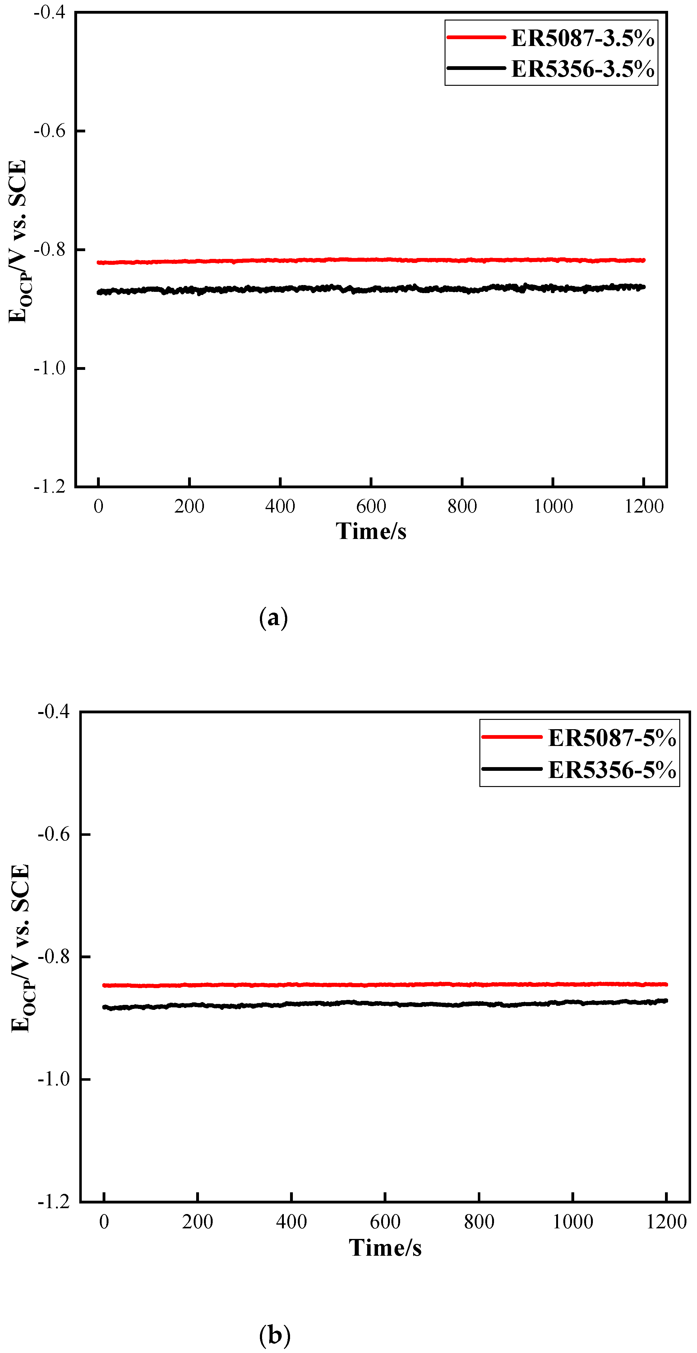
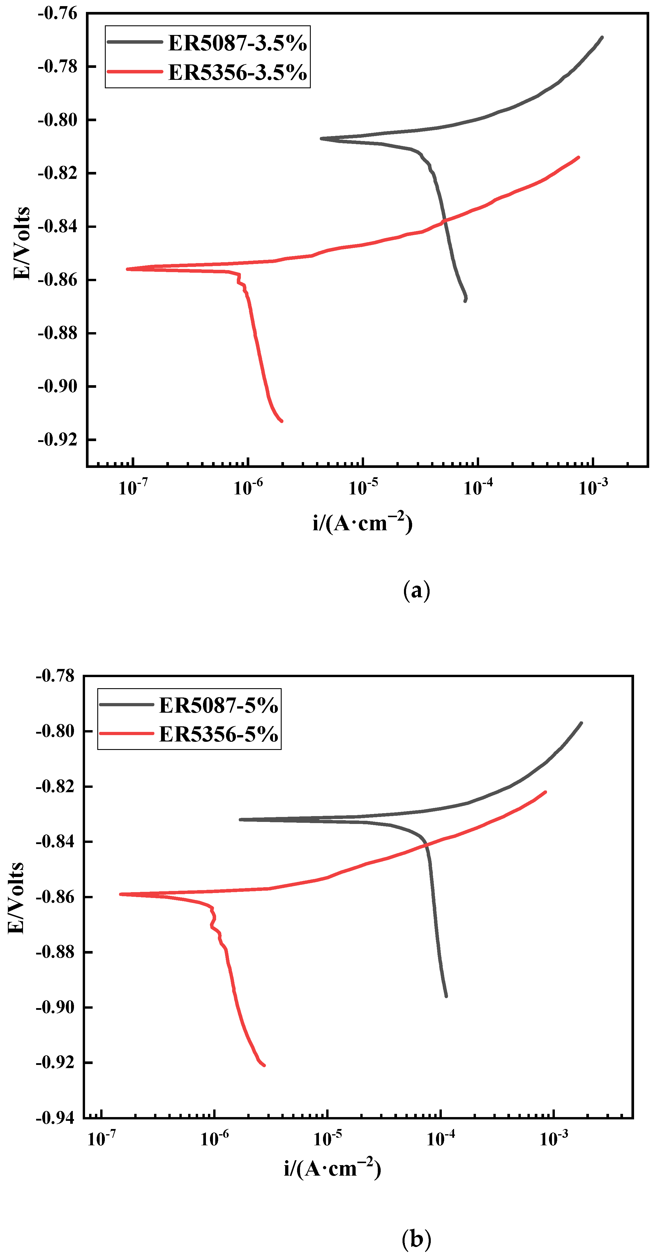
3.2. Polarization Curve

The OCP of the weld zones in ER5087 and ER5356 welded joints with 3.5 wt.% and 5 wt.% NaCl solutions, respectively, is shown in Figure 3. The OCP tended to be stable soon.
Figure 4 displays the polarization curve of weld zones in ER5087 and ER5356 welded joints at different concentrations of NaCl solution. The OCP and electrochemical parameters of the weld zones in ER5356 and ER5087 welded joints are listed in Table 4. The Ecorr is a thermodynamic index for estimating the tendency of electrochemical corrosion of metals under certain conditions, and a larger Ecorr indicates a higher surface stability. The Icorr is a kinetic index for evaluating the corrosion degree, and a bigger Icorr represents a higher corrosion rate [15]. In the same concentration of NaCl solution, the OCP and Ecorr of the weld zone in the ER5356 welded joint was slightly more negative than that in the ER5087 welded joint. The Icorr of the weld zone in the ER5087 welded joint was bigger than that in the ER5356 welded joint at the same NaCl concentration. The Icorr of the weld zone in 5 wt.% NaCl solution was bigger than that in 3.5 wt.% NaCl solution. The corrosion current density is higher. The corrosion resistance is worse. This indicated that the corrosion resistance in the weld zone of the ER5356 welded joint was better than that in the ER5087 welded joint, and the corrosion resistance of the weld zones in 3.5 wt.% solution was better than that in 5 wt.% solution.
Figure 4 shows that the cathodic polarization current was relatively low, and the anodic polarization part was not passivated. In neutral solution, the cathode part reacted as follows [16]:
H 2 O + 2 e H 2 + 2 OH
2 H 2 O + O 2 + 4 e 4 OH  
The dissolution of the aluminum alloy electrode produced a large number of soluble metal cations in the pores. In order to achieve electrical neutrality, Cl would diffuse and enrich into the closed cell. The metal chloride in the corrosion pit would be concentrated. However, the corrosion product Al3+ would hydrolyze to form more stable Al(OH)3. The anode part underwent metal oxidation reaction:
Al Al + 3 + 3 e
Al + 3 + 3 OH Al ( OH ) 3
The sample surface was covered by hydrogen bubbles, which resulted in relatively low cathode current density. The Al ( OH ) 3   formation of a corrosion deposition layer inhibited the external and local corrosion internal material transmission, and then formed blocked galvanic cell corrosion. Therefore, there was no passivation in the anodic polarization curve [17].

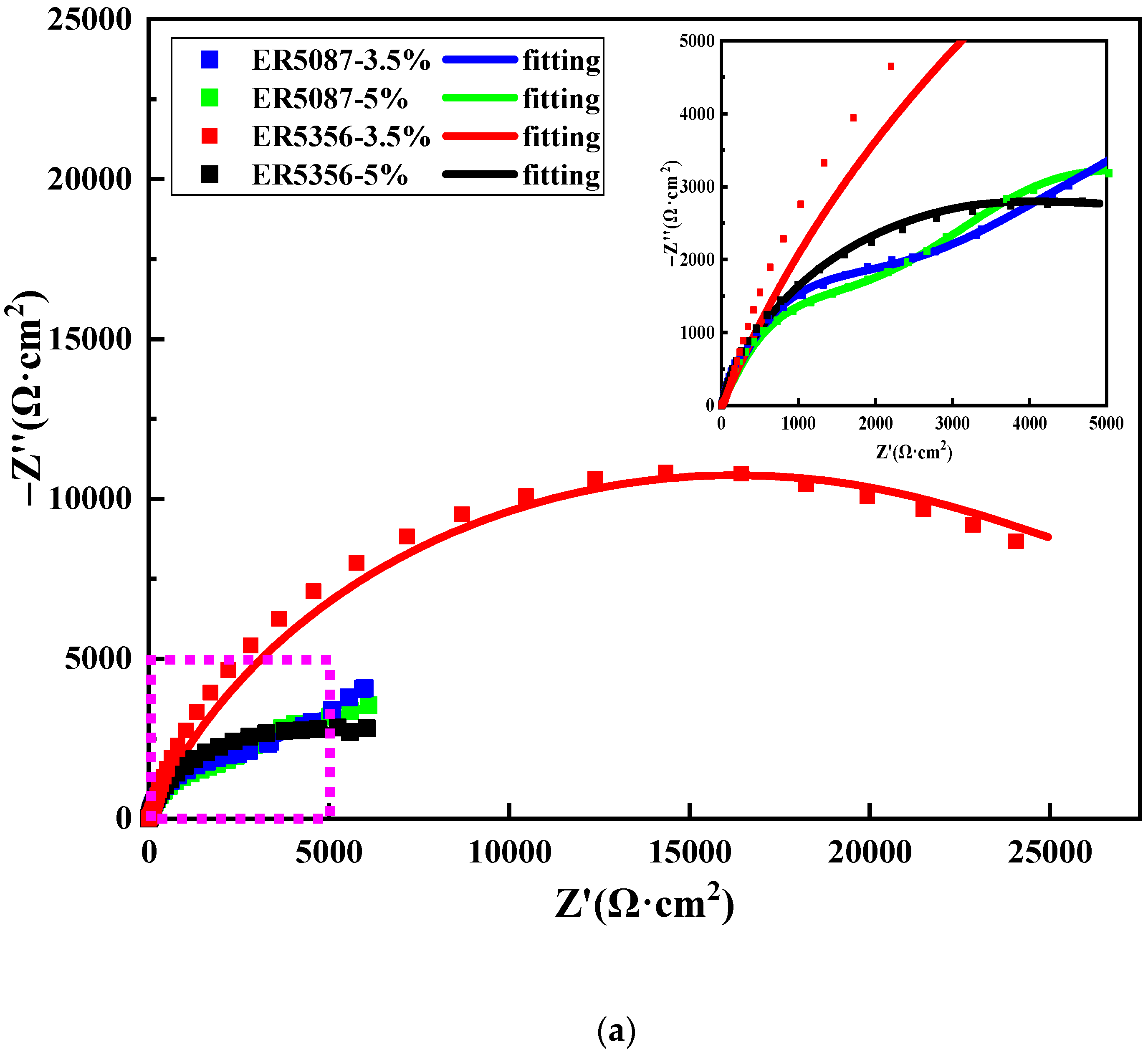
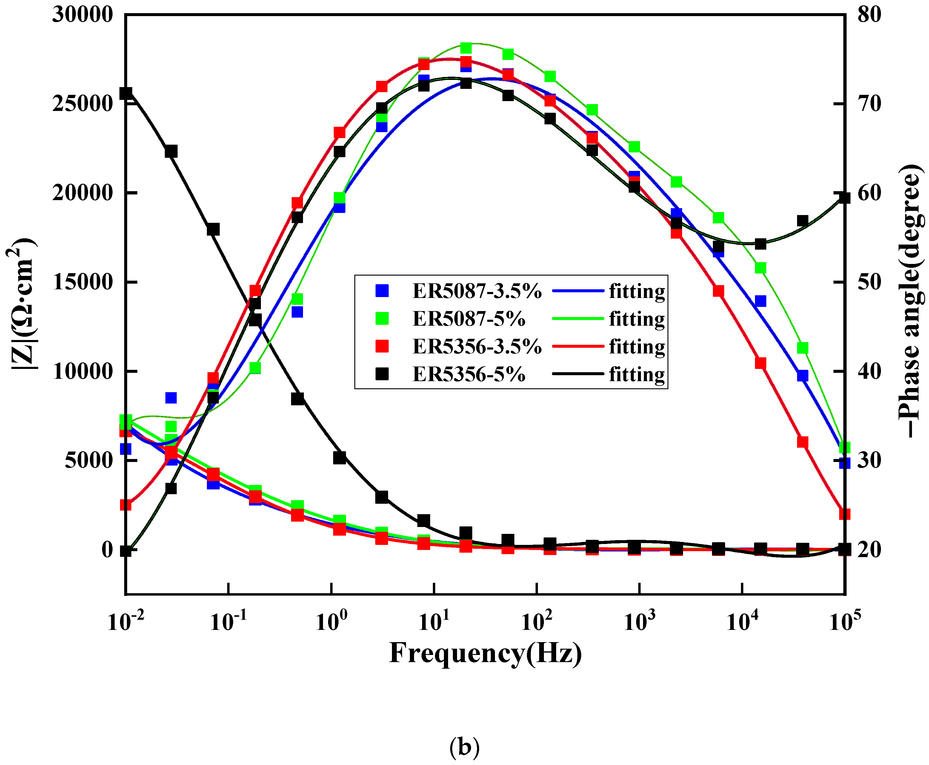
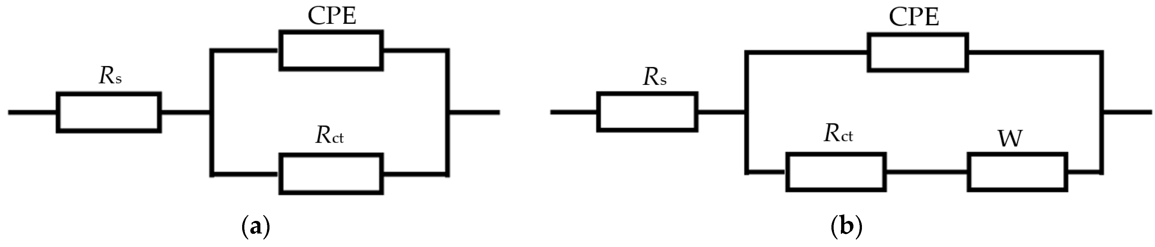
3.3. Electrochemical Impedance

Figure 5 reveals the Nyquist plot and Bode plot of the weld zones in ER5087 and ER5356 welded joints at different concentrations of NaCl solution (3.5 wt.% and 5 wt.%). The Nyquist plot shows a compressed semicircular capacitive reactance arc of the weld zone of the ER5356 welded joint, but there was a capacitive reactance arc in the high frequency region and a straight line at a certain angle in the low frequency region for the weld zone in the ER5087 welded joint (see Figure 5a). The capacitive arc represents the new interface produced by corrosion in the corrosion process. The larger the radius of capacitive arc, the stronger the corrosion resistance of the alloy. The straight line in the low frequency region indicated the existence of Warburg impedance diffusion behavior [18,19]. The transformation process of the impedance spectrum was mainly related to the dynamic transformation in the corrosion process, and the dynamic transformation changed from transfer control to diffusion control.
Figure 5b shows the Bode diagram of the weld zones in ER5087 and ER5356 welded joints in 3.5 wt.% and 5 wt.% NaCl solutions, respectively. The phase angles were less than 90°, indicating that there was a certain difference between the ideal capacitance and the electrochemical interface of the sample. With the increase of NaCl concentration, the corresponding impedance decreased, while the phase angle increased. This was because the increase of NaCl concentration and corrosion time made the charge transfer between the alloy and the solution easier, the corrosion rate faster, and corrosion products more abundant. Finally, the intermetallic compound particles in the corrosion pit slowly separated from the aluminum matrix [20].
The radius of capacitive arc and the impedance of the weld zone in the ER5356 welded joint were bigger than that in the ER5087 welded joint. This also proved that the corrosion resistance of the weld zone in the ER5356 weld joint was better than the ER5087 welded joint.
Figure 6 displays equivalent circuit diagram of EIS fitting. Table 5 shows The EIS electrochemical parameters of the weld zones in ER5356 and ER5087 welded joints. Rs denotes the solution resistance, Rct represents the charge transfer resistance, W and CPE are Warburg impedance and a constant phase element, respectively. CPE is related to the distribution of surface reactivity, non-uniformity, roughness, electrode porosity, and species adsorption [21]. Since there is almost no pure capacitance in the process of electrochemical corrosion, CPE is usually applied to make the fitting the electrochemical data more accurate. The impedance of CPE can be expressed by the following formula [22]:
Z C P E = 1 Y ( j ω ) n
where Y represents the dimension of CPE, j represents the imaginary number, ω = 2πf is the angular frequency (rad/s) (f represents the frequency, the unit is Hz), and n is the index related to the diffusion effect of capacitive reactance. If n = 0, CPE represents a pure resistor, n = 1, a pure capacitor, and if n = 0.5, a Warburg impedance with diffusion characteristics.
The Rct is usually used to evaluate the sensitivity, and the smaller Rct value represents a higher corrosion current density and thus a worse corrosion resistance [23]. The Rct of the weld zones in ER5087 and ER5356 weld joints gradually decreased with the increase of NaCl concentration, indicating that the surface activity of the two kinds of weld zones increased correspondingly, and the corrosion inhibition ability decreased. This was because with the increase of NaCl concentration, the electrolyte in the solution increases, which accelerates the speed of ion exchange in the solution and reduces the Rs. n decreased with the increase of NaCl concentration, which indicated that the smoothness of the electrode surface decreases. The increase of NaCl concentration intensified the damage of Cl to the metal matrix. Pitting corrosion occurred on the surface of the aluminum alloy and intensified the surface heterogeneity, and the dispersion effect enhanced with the increase of NaCl concentration.
Under the same NaCl concentration, the Rct of the weld zone in the ER5356 welded joint was bigger than that in the ER5087 welded joint, indicating that the corrosion resistance of the weld zone in ER5356 weld joint was better than that in the ER5087 welded joint.
The corrosion performance of weld zones mainly depends on the microstructure and electrochemical properties near the grain boundary [24,25]. The microstructure near the grain boundary mainly refers to the distribution of precipitates at the grain boundary. When the precipitates at the grain boundary were continuously distributed, a continuous corrosion channel will be formed, which will reduce the corrosion resistance of the alloy [26,27,28]. A large number of grain boundary precipitates and segregation along grain boundaries existed in the weld zone of the ER5087 welded joint. While the precipitates and segregation were mainly dispersed in the weld zone of the ER5356 welded joint (see Figure 2), so the weld zone in the ER5356 welded joint had a better corrosion resistance than that of the ER5087 welded joint.
On the other hand, the electrochemical properties of precipitates at grain boundaries and nearby micro regions will also lead to corrosion differences [29,30]. ER5356 and ER5087 welding wires are both Al-Mg alloys, Al-Mg welding wires increases the content of Mg in the weld zone and forms strengthening phase Al8Mg5 (β phase) [4,5,31]. When the content of Mg element in Al-Mg alloy exceeded 3%, it was very sensitive to stress corrosion cracking due to the precipitation of Al8Mg5 at the grain boundary, which was an anode relative to the matrix α-Al and would be preferentially corroded [32,33]. Therefore, the corrosion resistance of the weld mainly depends on the microstructure quantity as well as the size and distribution of the β-Al8Mg5 [34]. ER5087 welding wire contains more Mn element, which reduces the solubility of Mg in the matrix α-Al to make more β-Al8Mg5 precipitate phases, resulting in lower corrosion resistance.
Therefore, the electrochemical corrosion resistance of the weld zone in the ER5087 welded joint was worse than that of the ER5356 welded joint.

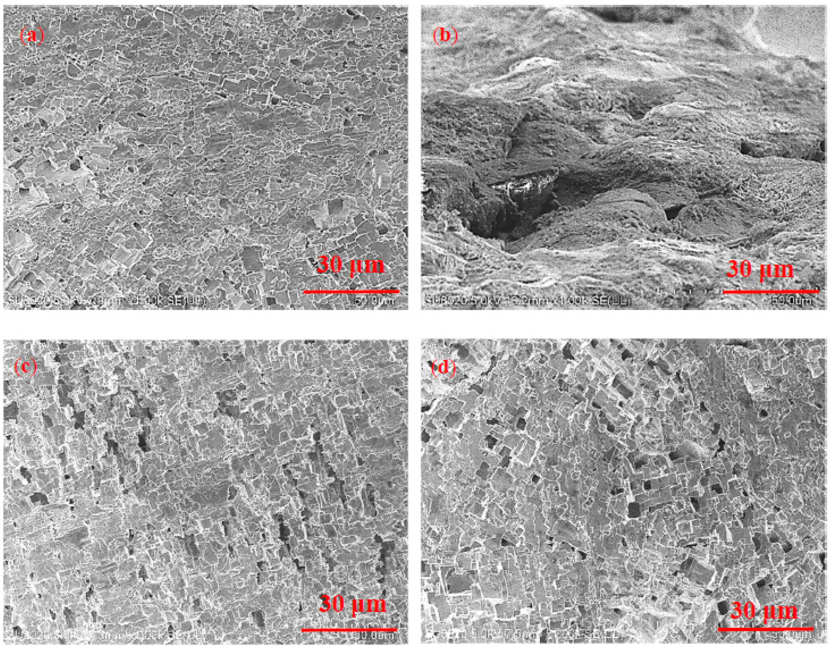
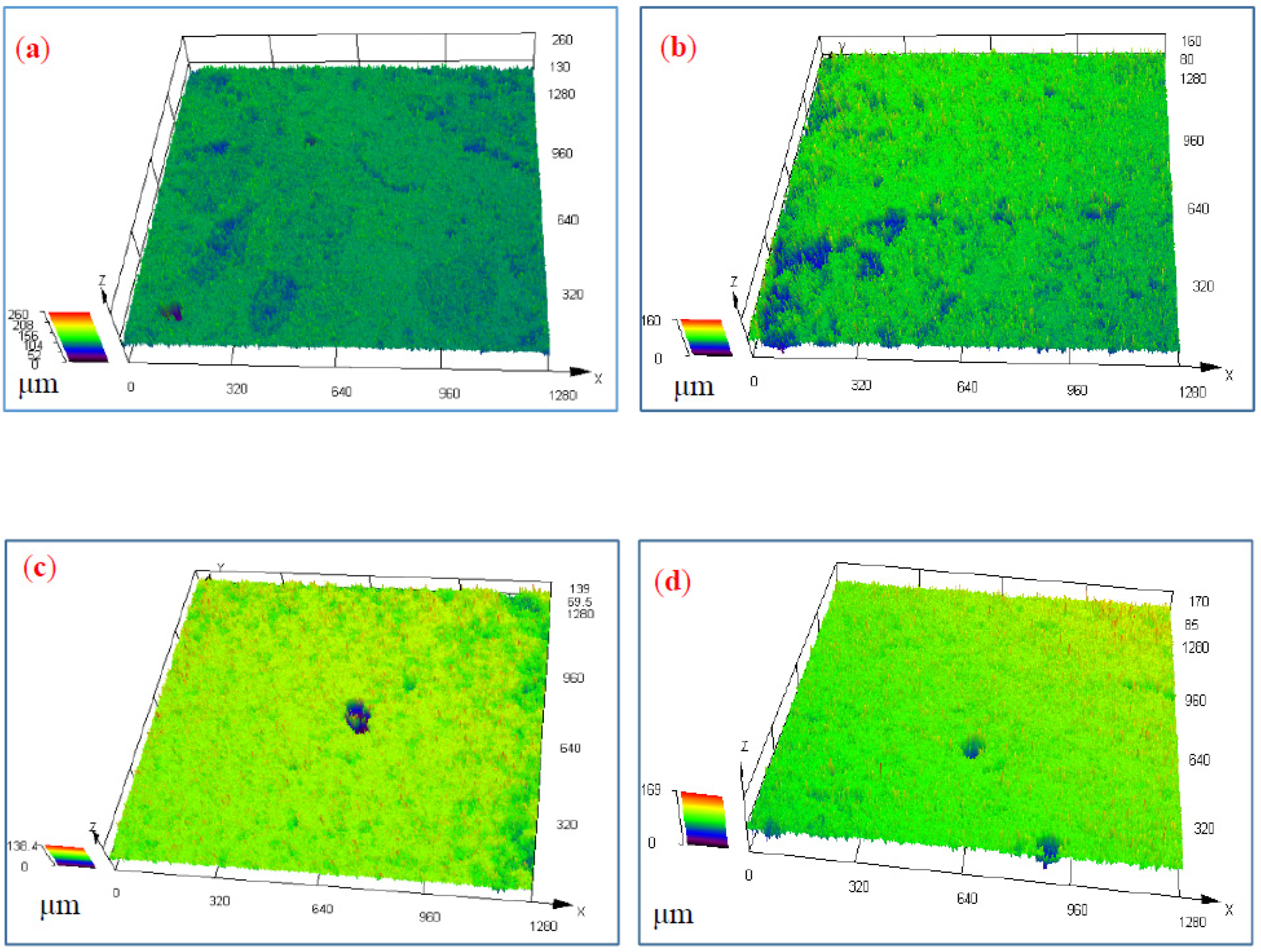
3.4. Surface Morphology after Corrosion

Figure 7 shows the SEM of the weld zones in ER5356 and ER5087 welded joints in 3.5 wt.% NaCl and 5 wt.% NaCl solutions after electrochemical corrosion. There were many different sized pits on the surface of the samples (Figure 7a). In 5 wt.% NaCl solution (Figure 7b), the weld zone of ER5087 welded joint showed small pitting pits connected to form larger diameter pitting pits, and cracks appeared in the pitting pits. This indicated that intergranular corrosion occurs. The corrosion mechanism of the weld zone in ER5087 welded joint at 5 wt.% NaCl solution developed from pitting corrosion to intergranular corrosion. The surface pitting of the weld zone in the ER5356 welded joint in 5 wt.% NaCl solution (Figure 7d) was more severe than that in 3.5 wt.% NaCl solution (Figure 7c). There was pitting on the surface, and the pitting was not interconnected.
Compared with the weld zone of the ER5356 welded joint, the weld zone of the ER5087 welded joint contained more Zn. The higher content of Zn promoted the formation of the Zn-rich phase (see Figure 3), which was dissolved and continuously distributed along the grain boundary due to electrochemical reaction, resulting in the grain boundary becoming an anode active channel, which made the corrosion develop into the interior of the metal [35], leading to the occurrence of intergranular corrosion.
With the competitive adsorption of Cl and oxygen in NaCl solution, Cl will gradually replace OH to produce AlCl3 [36], leading to the formation of corrosion pits. The reaction formula is as follows [37]:
Al ( OH ) 3 + Cl Al ( OH ) 2 Cl + OH
Al ( OH ) 2 Cl + Cl Al ( OH ) Cl 2 + OH
Al ( OH ) Cl 2 + Cl AlCl 3 + OH
For the weld zone in the ER5087 welded joint at 5 wt.% NaCl solution, more Cl was adsorbed onto the active surface of weld zones, which accelerated the corrosion, resulting in the corrosion mechanism from pitting to intergranular corrosion. The corrosion products generated at the grain boundaries would expand the volume, resulting in slightly discontinuous protrusions on the metal surface, which might cause metal spalling in severe cases.
Figure 8 shows LSCM of two kinds of weld zones under different concentrations of NaCl solutions. The results show that there were some corrosion pits. The corrosion degree enhanced, and the corrosion point diffused in 5 wt.% NaCl solution. There were more corrosion pits in the weld zone of the ER5087 welded joint than ER5356 welded joint.
In order to analyze the difference of corrosion pits of the weld zones in ER5356 and ER5087 welded joints under different NaCl concentration, the max depth (dmax) of corrosion pits was measured by LSCM. Table 6 shows the dmax of corrosion pit in weld zones. In the same NaCl concentration, the dmax of the corrosion pit of the weld zone in the ER5087 welded joint was bigger than that in the ER5356 welded joint. The dmax of the corrosion of the weld zone in the ER5356 welded joint with 5 wt.% NaCl was 78.5 ± 0.96 μm, which was much bigger than that with 3.5 wt.% NaCl concentration. The dmax of the corrosion pit with 5 wt.% NaCl solution was bigger than that with 3.5 wt.% NaCl solution.

4. Conclusions

In this study, 7N01-T4 aluminum alloy was welded by MIG with ER5087 and ER5356 welding wires, respectively. The electrochemical corrosion behavior of the two kinds of weld zones when immersed into 3.5 wt.% and 5 wt.% NaCl solution was investigated. The following conclusions can be drawn:
(1)
The results of the polarization curve and EIS indicated the better corrosion resistance of the weld zone in the ER5356 welded joint compared to that in the ER5087 welded joint, which was related to the different contents of Mn and Zn elements and distribution of precipitates for the weld zones in the two kinds of welded joints.
(2)
The dmax for corrosion pits of the weld zone in the ER5356 welded joint was smaller than that in the ER5087 welded joint when immersed in the same NaCl concentrations. The dmax of the corrosion pit of the weld zone in the ER5356 welded joint with 5 wt.% NaCl solution was 78.5 ± 0.96 μm, which was much bigger than that with 3.5 wt.% NaCl solution. For the weld zone in the ER5087 welded joint with 5 wt.% NaCl solution, more Cl was adsorbed onto the active surface of weld zones, which accelerated the corrosion, resulting in the corrosion mechanism from pitting to intergranular corrosion.

Author Contributions

Conceptualization, M.W. and D.L.; Data curation, P.W., Y.L. and Z.D.; Formal analysis, Z.Z.; Funding acquisition, D.L. and P.W.; Investigation, Z.Z., Y.L. and Z.D.; Methodology, M.W.; Writing—original draft, P.W.; Writing—review & editing, D.L. and P.W.; All authors have read and agreed to the published version of the manuscript.

Funding

This research was supported by Postdoctoral Research Foundation of China (Grant No. 2016M601753), ‘Blue and Green Project’ of Universities of Jiangsu Province and Major Projects of Natural Sciences of University in Jiangsu Province of China (Grant No. 19KJA460009), Graduate Research and Innovation Projects of Jiangsu Province (Grant No. KYCX21_3450), and Natural Science Foundation of Jiangsu Province (Grant No. BK20201453).

Acknowledgments

The authors would like to thank Pingyi Guo and Xiaowei Zhou of Jiangsu University of Science and Technology for their advice.

Conflicts of Interest

The authors declare no conflict of interest.

References

  1. Liu, W.; Wu, D.; Duan, S.; Wang, T.; Zou, Y. A study on fatigue crack propagation for friction stir welded plate of 7N01 Al-Zn-Mg alloy by EBSD. Materials 2020, 13, 330. [Google Scholar] [CrossRef] [PubMed] [Green Version]
  2. Li, S.; Dong, H.; Li, P.; Chen, S. Effect of repetitious non-isothermal heat treatment on corrosion behavior of Al-Zn-Mg alloy. Corros. Sci. 2018, 131, 278–289. [Google Scholar] [CrossRef]
  3. Xie, H.; Xiao, Z.; Li, Z.; Wang, M.; Ma, S.; Jiang, H. Quench sensitivity of AA7N01 alloy used for high-speed train body structure. JOM 2018, 71, 1681–1686. [Google Scholar] [CrossRef]
  4. Wang, X.M.; Zhao, J.J.; Gou, G.Q. Research on Salt Fog Corrosion Behavior of Welded Joint of 7N01-T4 Aluminum Alloy for High-Speed Train. Adv. Mater. Res. 2011, 239, 2822–2826. [Google Scholar] [CrossRef]
  5. Wang, X.M.; Gou, G.Q.; Zhao, J.J.; Liu, Y. Study on the intergranular corrosion behavior of welding joint of A7N01-T4 Al-Alloy for high-speed train. Adv. Mater. Res. 2011, 284, 1594–1597. [Google Scholar] [CrossRef]
  6. Lin, H.-Q.; Ye, L.-Y.; Sun, L.; Xiao, T.; Liu, S.-D.; Deng, Y.-L.; Zhang, X.-M. Effect of three-step homogenization on microstructure and properties of 7N01 aluminum alloys. Trans. Nonferrous Met. Soc. China 2018, 28, 829–838. [Google Scholar] [CrossRef]
  7. Deng, Y.; Peng, B.; Xu, G.; Pan, Q.; Yin, Z.; Ye, R.; Wang, Y.; Lu, L. Effects of Sc and Zr on mechanical property and microstructure of tungsten inert gas and friction stir welded aerospace high strength Al–Zn–Mg alloys. Mater. Sci. Eng. A 2015, 639, 500–513. [Google Scholar] [CrossRef]
  8. Xie, H.; Hu, L.; Ma, Q.-H.; Meng, W.; Yin, X.-H. Microstructure and mechanical properties of A7N01 aluminum alloy weld joints filled with ER5356 and ER5087 weld wires. J. Min. Met. Sect. B Met. 2022, 58, 157–167. [Google Scholar] [CrossRef]
  9. Liu, D.; Wei, P.; Long, W.; Zhou, W.; Wu, M.; Wang, J. Effect of welding wires on fatigue property of 7N01-T4 aluminium alloy joints. Sci. Technol. Weld. Join. 2020, 26, 1–10. [Google Scholar] [CrossRef]
  10. Zhang, Z.Q.; Li, Y.; Xing, Y.S.; Yin, H.; He, C.S. Change of Intergranular Corrosion Behavior along the Thickness in a Friction-Stir-Welded 7N01-T5 Aluminum Alloy. Mater. Sci. Forum 2018, 941, 1754–1759. [Google Scholar] [CrossRef]
  11. Huang, S.; Xu, L.; Chen, H.; Che, X.; Wang, Y.; Yang, X. Effect of laser repairing on corrosion behaviour of metal–inert gas welding joint of 7N01 aluminium alloy. Mater. Corros. 2019, 70, 1578–1592. [Google Scholar] [CrossRef]
  12. Pan, Y.; Wang, Y.; Guo, F.; Zhang, T.; Matsuda, K.; Wu, D.; Zhang, Y.; Zou, Y. Stress corrosion behavior of friction stir welding joint of 7N01 aluminum alloy. J. Mater. Res. Technol. 2021, 15, 1130–1144. [Google Scholar] [CrossRef]
  13. Wang, X.; Liao, X.; Ma, C.; Zhang, S.; Liu, Y.; Chen, H. Effects of chemical composition on the corrosion behavior of A7N01S-T5 Al alloys. Int. J. Mod. Phys. B 2015, 29, 1540025. [Google Scholar] [CrossRef]
  14. Chen, J.; Wu, Y.; Zhang, K. Effect of welding thermal cycle on corrosion behavior of 7N01 alloy. Mater. Express 2020, 10, 2130–2142. [Google Scholar] [CrossRef]
  15. Zheng, Y.; Li, Y.; Chen, J.H.; Zou, Z.Y. Effects of tensile and compressive deformation on corrosion behavior of a Mg-Zn alloy. Corros. Sci. 2015, 90, 445–450. [Google Scholar] [CrossRef]
  16. Kannan, M.B.; Raja, V. Influence of Heat Treatment and Scandium Addition on the Electrochemical Polarization Behavior of Al-Zn-Mg-Cu-Zr Alloy. Met. Mater. Trans. A 2007, 38, 2843–2852. [Google Scholar] [CrossRef]
  17. Xu, W.; Liu, J. Microstructure and pitting corrosion of friction stir welded joints in 2219-O aluminum alloy thick plate. Corros. Sci. 2009, 51, 2743–2751. [Google Scholar] [CrossRef]
  18. Macdonald, D.D. Reflections on the history of electrochemical impedance spectroscopy. Electrochim. Acta 2006, 51, 1376–1388. [Google Scholar] [CrossRef]
  19. Liu, C.; Bi, Q.; Leyland, A.; Matthews, A. An electrochemical impedance spectroscopy study of the corrosion behaviour of PVD coated steels in 0.5 N NaCl aqueous solution: Part II.: EIS interpretation of corrosion behaviour. Corros. Sci. 2003, 45, 1257–1273. [Google Scholar] [CrossRef]
  20. Mazinani, S.; Samsami, A.; Jahanmiri, A.; Sardarian, A. Experimental study on equilibrium solubility (at low partial pressures), density, viscosity and corrosion rate of carbon dioxide in aqueous solutions of ascorbic acid. Fluid Phase Equilibria 2011, 305, 39–42. [Google Scholar] [CrossRef]
  21. Brug, G.J.; Van Den Eeden, A.L.G.; Sluyters-Rehbach, M.; Sluyters, J.H. The analysis of electrode impedances complicated by the presence of a constant phase element. J. Electroanal. Chem. Interfacial Electrochem. 1984, 176, 275–295. [Google Scholar] [CrossRef]
  22. Lasia, A.; White, B.E. Modern Aspects of Electrochemistry; Kluwer Academic/Plenum Publishers: Boston, NY, USA, 1999; Volume 32, pp. 143–248. [Google Scholar]
  23. Li, S.; Dong, H.G.; Wang, X.X.; Liu, Z.Y. Quenching sensitivity of Al-Zn-Mg alloy after non-isothermal heat treatment. Materials 2019, 12, 1595. [Google Scholar] [CrossRef] [PubMed] [Green Version]
  24. Tavares, S.; Pardal, J.; Lima, L.; Bastos, I.; Nascimento, A.; de Souza, J. Characterization of microstructure, chemical composition, corrosion resistance and toughness of a multipass weld joint of superduplex stainless steel UNS S32750. Mater. Charact. 2007, 58, 610–616. [Google Scholar] [CrossRef]
  25. Song, F.X.; Zhang, X.M.; Liu, S.D.; Tan, Q.; Li, D.F. The effect of quench transfer time on microstructure and localized corrosion behavior of 7050-T6 Al alloy. Mater. Corros. 2014, 65, 1007–1016. [Google Scholar] [CrossRef]
  26. Liu, S.; Chen, B.; Li, C.; Dai, Y.; Deng, Y.; Zhang, X. Mechanism of low exfoliation corrosion resistance due to slow quenching in high strength aluminium alloy. Corros. Sci. 2015, 91, 203–212. [Google Scholar] [CrossRef]
  27. Song, F.; Zhang, X.; Liu, S.; Tan, Q.; Li, D. The effect of quench rate and overageing temper on the corrosion behaviour of AA7050. Corros. Sci. 2014, 78, 276–286. [Google Scholar] [CrossRef]
  28. Jiang, J.T.; Xiao, W.Q.; Yang, L.; Shao, W.Z.; Yuan, S.J.; Zhen, L. Ageing behavior and stress corrosion cracking resistance of a non-isothermally aged Al–Zn–Mg–Cu alloy. Mater. Sci. Eng. A 2014, 605, 167–175. [Google Scholar] [CrossRef]
  29. Chen, J.; Zhang, X.; Zou, L.; Yu, Y.; Li, Q. Effect of precipitate state on the stress corrosion behavior of 7050 aluminum alloy. Mater. Charact. 2016, 114, 1–8. [Google Scholar] [CrossRef]
  30. Huang, L.; Chen, K.; Li, S. Influence of grain-boundary pre-precipitation and corrosion characteristics of inter-granular phases on corrosion behaviors of an Al–Zn–Mg–Cu alloy. Mater. Sci. Eng. B 2012, 177, 862–868. [Google Scholar] [CrossRef]
  31. Røyset, J.; Ryum, N. Scandium in aluminium alloys. Int. Mater. Rev. 2005, 50, 19–44. [Google Scholar] [CrossRef]
  32. Davies, J.R. Corrosion of Aluminum and Aluminum Alloys; ASM International: Almere, The Netherlands, 1999. [Google Scholar]
  33. Sampath, D.; Moldenhauer, S.; Schipper, H.; Mechsner, K.; Haszler, A. Decomposition of Solid Solution of the AA5083 Alloy upon Exposure to Elevated Temperatures. Mater. Sci. Forum 2000, 331, 1089–1094. [Google Scholar] [CrossRef]
  34. Engler, O.; Kuhnke, K.; Krupp, H.-J.; Hentschel, T. Characterization of Intergranular Corrosion in AA 5xxx Al-Mg Alloys. Prat. Met. 2020, 57, 545–568. [Google Scholar] [CrossRef]
  35. Xiao, Y.-P.; Pan, Q.-L.; Li, W.-B.; Liu, X.-Y.; He, Y.-B. Influence of retrogression and re-aging treatment on corrosion behaviour of an Al–Zn–Mg–Cu alloy. Mater. Des. 2011, 32, 2149–2156. [Google Scholar] [CrossRef]
  36. Morad, M.S. Some environmentally friendly formulations as inhibitors for mild steel corrosion in sulfuric acid solution. J. Appl. Electrochem. 2007, 37, 661–668. [Google Scholar] [CrossRef]
  37. Liu, Y.X.; Sun, Z.; He, D.Y.; Lin, J.J.; Wang, K.B.; Zhao, X.; Lv, Y.H. Corrosion Behavior of 7A52 Aluminum Alloy Plasma Arc Welding Joint in Simulated Marine Atmosphere Environment. Adv. Mater. Res. 2022, 1170, 39–48. [Google Scholar] [CrossRef]
Figure 1. Sampling location in different welded joints for electrochemical corrosion test, (a) ER5087 welded joint, (b) ER5356 welded joint.
Materials 15 03737 g001
Figure 2. SEM and EDS results for the two kinds of weld zones, (a,c) ER5087, (b,e) ER5356, (d) EDS for point A, (f) EDS for point B.
Materials 15 03737 g002
Figure 3. OCP of the weld zones in ER5087 and ER5356 welded joints at different concentrations of NaCl solution. (a) 3.5 wt.% NaCl solution, (b) 5 wt.% NaCl solution.
Materials 15 03737 g003
Figure 4. Polarization curve of the weld zones in ER5087 and ER5356 welded joints at different concentrations of NaCl solution. (a) 3.5 wt.% NaCl solution, (b) 5 wt.% NaCl solution.
Materials 15 03737 g004
Figure 5. Impedance spectrum in the weld zones in ER5356 and ER5087 welded joints at different NaCl concentration (a) Nyquist plots, (b) Bode plots.
Materials 15 03737 g005aMaterials 15 03737 g005b
Figure 6. Equivalent circuit diagram of EIS fitting. (a) the weld zone of ER5356 welded joint, (b) the weld zone of ER5087 welded joint.
Materials 15 03737 g006
Figure 7. SEM for the kinds of two kinds of weld zones after electrochemical corrosion, (a) ER5087-3.5%, (b) ER5087-5%, (c) ER5356-3.5%, and (d) ER5356-5%.
Materials 15 03737 g007
Figure 8. LSCM corrosion morphology for two kinds of weld zones, (a) ER5087-3.5%, (b) ER5087-5%, (c) ER5356-3.5%, and (d) ER5356-5%.
Materials 15 03737 g008
Table 1. Chemical compositions of 7N01-T4 aluminum alloy and welding wires (wt.%).
AlloySiFeCuMnMgZnTiCrZrAl
7N01-T4≤0.30≤0.30≤0.200.2–0.71.0–2.04.0–5.0≤0.20≤0.30Bal.
ER53560.050.10<0.010.145.00<0.010.070.06Bal.
ER50870.250.400.050.904.800.250.150.150.15Bal.
Table 2. MIG welding process parameters of 7N01-T4 aluminum alloy.
Weld Pass No.Welding Current/AWelding Voltage/VWelding Speed/(mm∙s−1 )
1250248
226024.57
3250247
Table 3. The abbreviation of samples in this paper.
AcronymsNotes
ER5087-3.5%The weld zone of ER5087 welded joint in 3.5 wt.% NaCl solution
ER5087-5%The weld zone of ER5087 welded joint in 5 wt.% NaCl solution
ER5356-3.5%The weld zone of ER5356 welded joint in 3.5 wt.% NaCl solution
ER5356-5%The weld zone of ER5356 welded joint in 5 wt.% NaCl solution
Table 4. The OCP and polarization curve electrochemical parameters of the weld zone in ER5356 and ER5087 welded joints.
SampleOCP (mV)Ecorr (mV)Icorr (10−7A·cm−2)
ER5087-3.5% −817.6 ± 2−807 ± 449.4 ± 0.3
ER5087-5% −845.6 ± 1−832 ± 376.5 ± 0.4
ER5356-3.5% −863.1 ± 1.5−856 ± 35.1 ± 1.2
ER5356-5% −871 ± 2−859 ± 29.8 ± 0.5
Table 5. The EIS electrochemical parameters of the weld zones in ER5356 and ER5087 welded joints.
SampleRs (Ω·cm2)CPERct (KΩ·cm2)YW
(10−4 Ω−1·cm−2·s−0.5)
Y0 (10−6Ω−1·cm−2·s−n)n (0 < n < 1)
ER5087-3.5%2.5357.49 ± 1.560.818.03 ± 0.233.44 ± 0.80
ER5087-5%2.1771.60 ± 1.820.797.76 ± 0.183.82 ± 0.78
ER5356-3.5%5.2420.63 ± 0.440.8234.01 ± 0.16
ER5356-5%3.0974.52 ± 1.220.747.89 ± 0.21
Table 6. The dmax of corrosion pit in the weld zones.
Sampledmax (μm)
ER5087-3.5%71 ± 0.89
ER5087-5%86 ± 1.20
ER5356-3.5%53 ± 0.45
ER5356-5%78.5 ± 0.96
Publisher’s Note: MDPI stays neutral with regard to jurisdictional claims in published maps and institutional affiliations.

