
Composite Detectors Based on Single-Crystalline Films and Single Crystals of Garnet Compounds

 , , ,
, , , 
Abstract
:1. Introduction
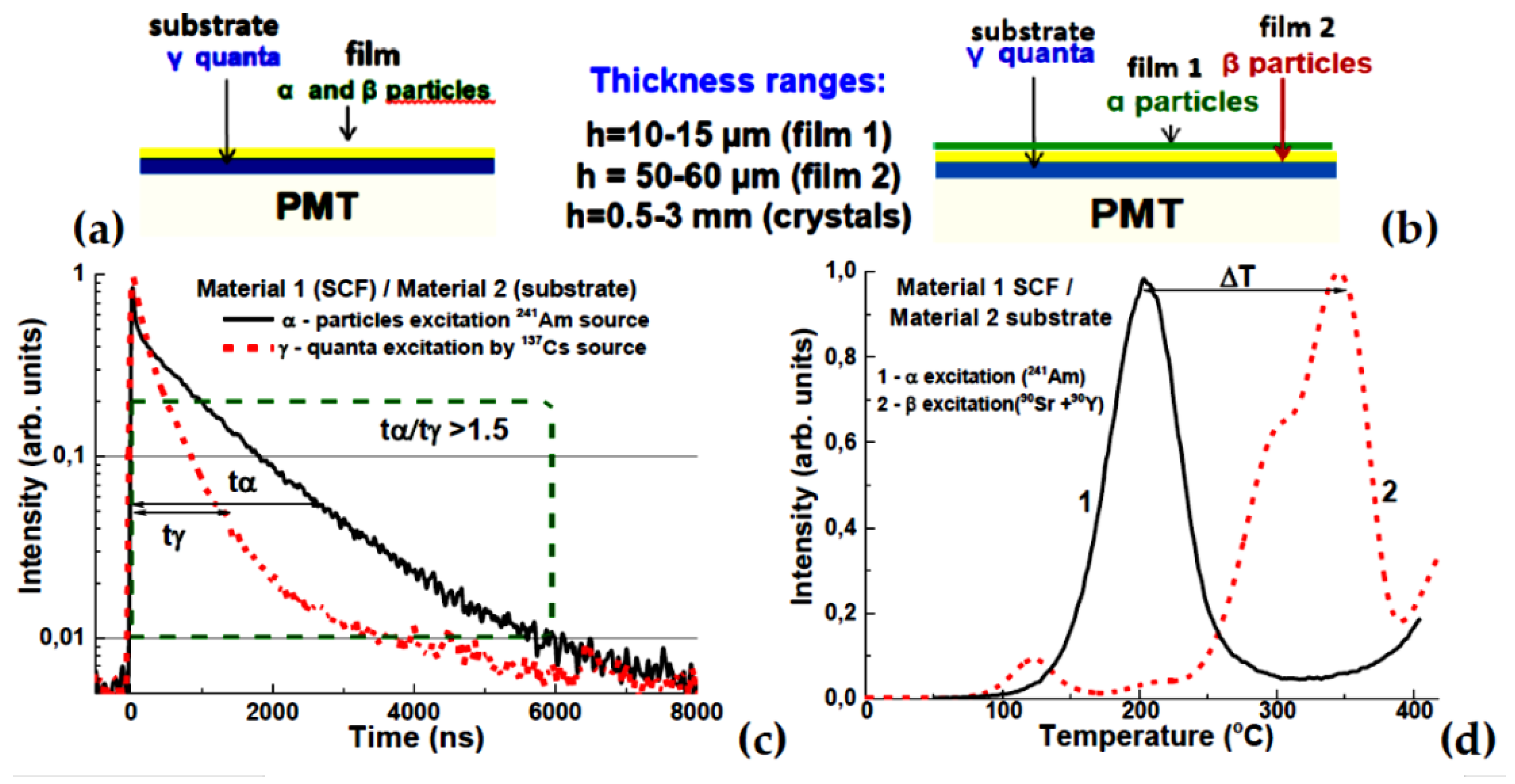
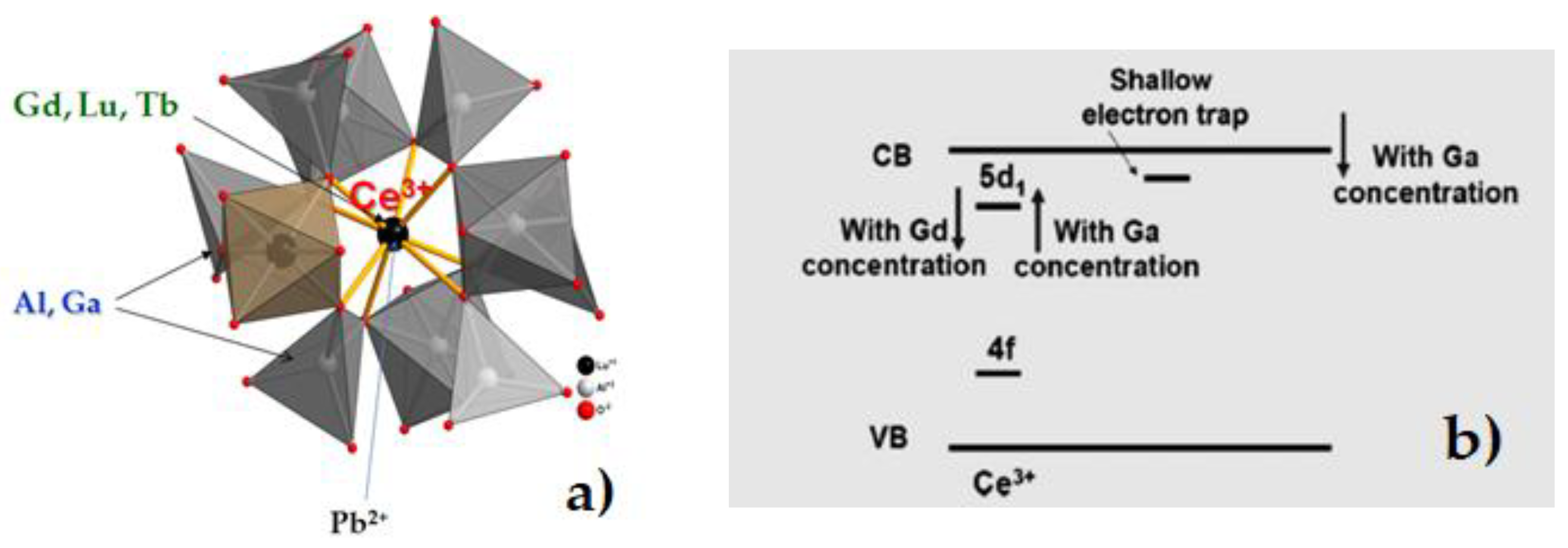
1.1. Composite Scintillators and TL Detectors: Fundamentals
1.2. Composite Scintillators and TL Detectors: History and Perspective
2. Materials and Methods
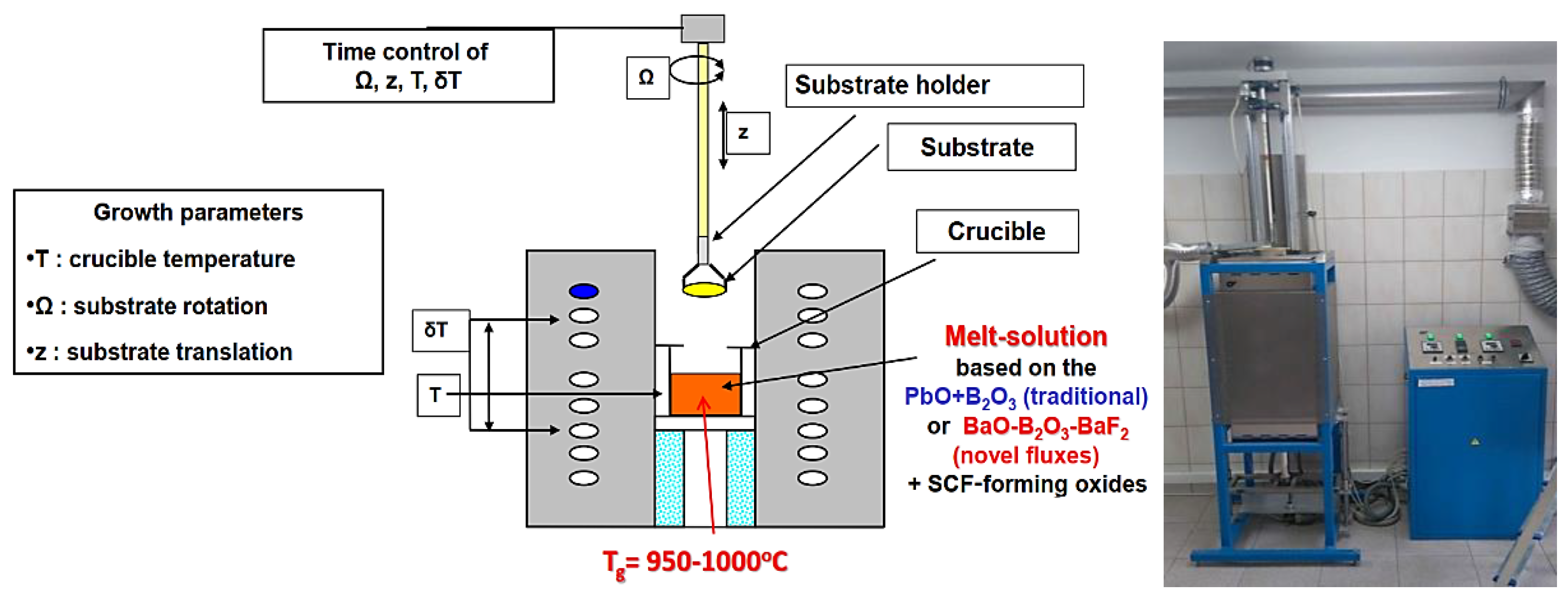
2.1. Crystallization of Scintillation Films by LPE Method
2.2. Characterization of Composite Scintillators and TL Detectors
3. Results
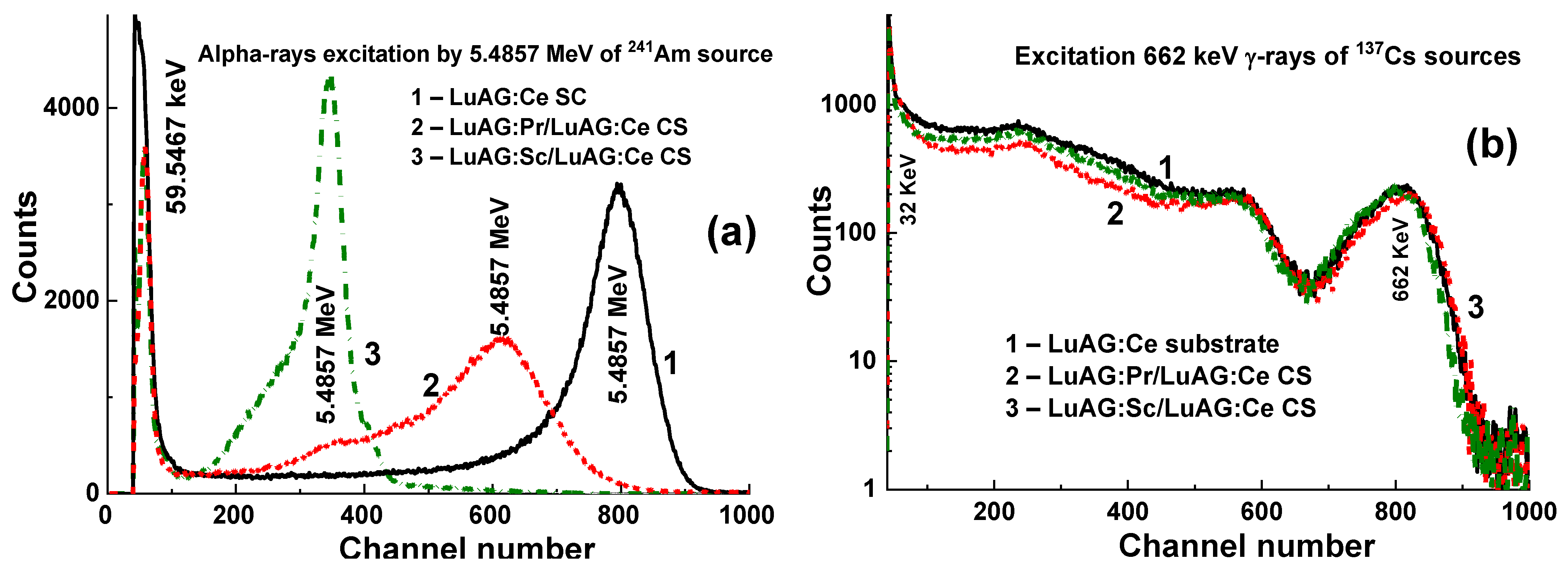
3.1. Composite Scintillators Based on LuAG Substrates Doped with Pr, Sc, and Ce Ions
3.1.1. Substrates Based on LuAG Crystals
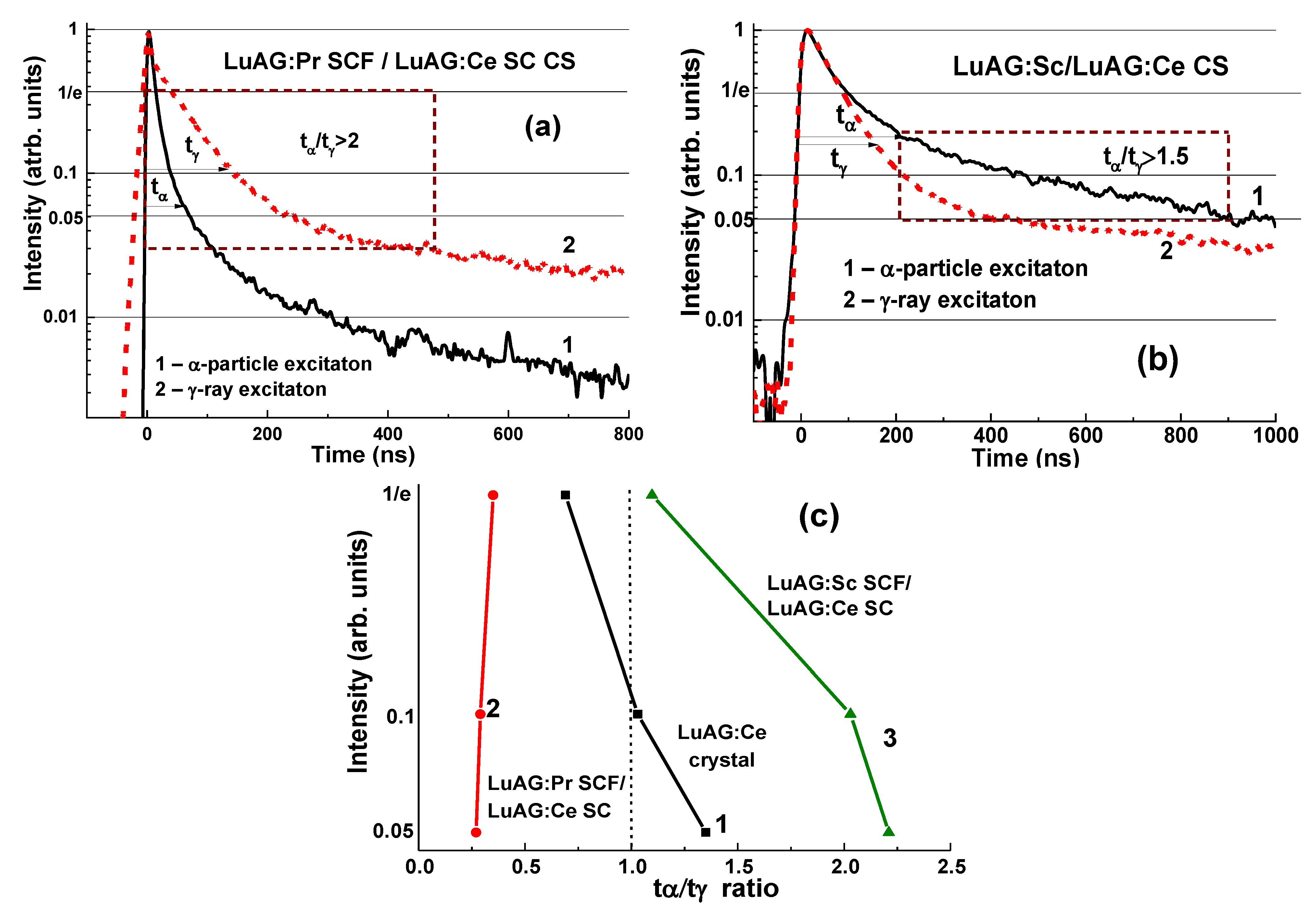
3.1.2. Composite Scintillators Based on LuAG:Ce Substrates
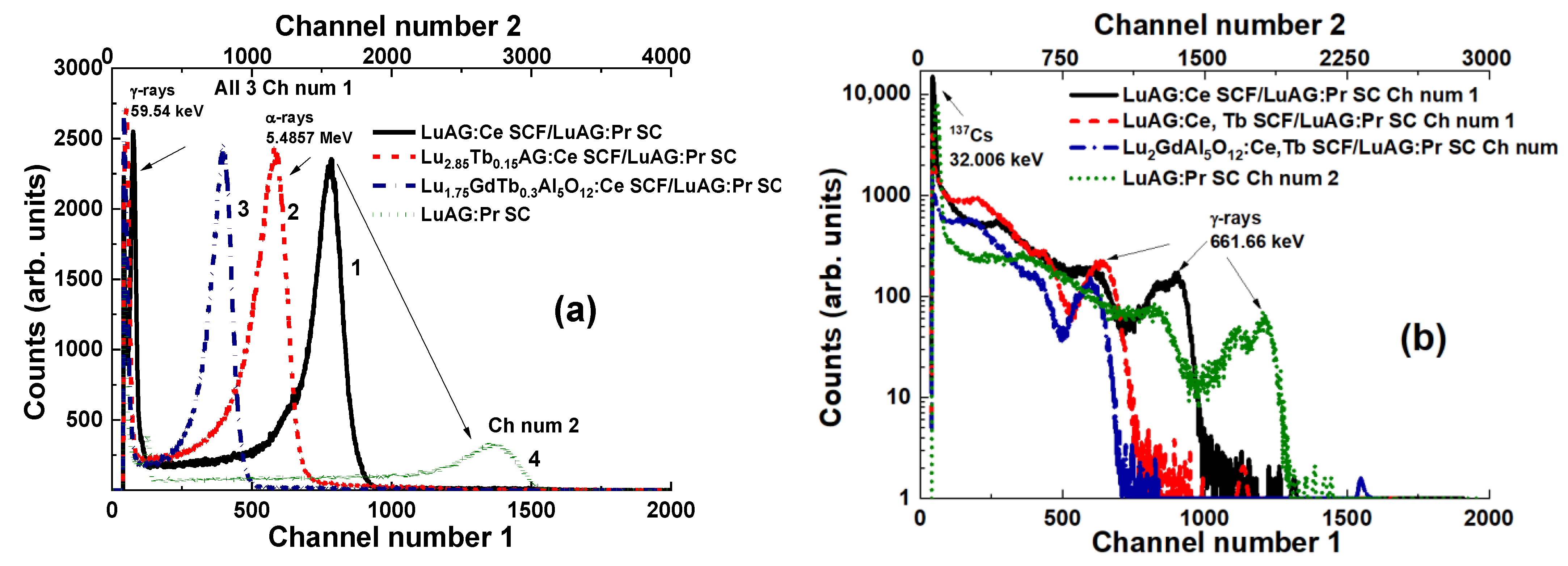
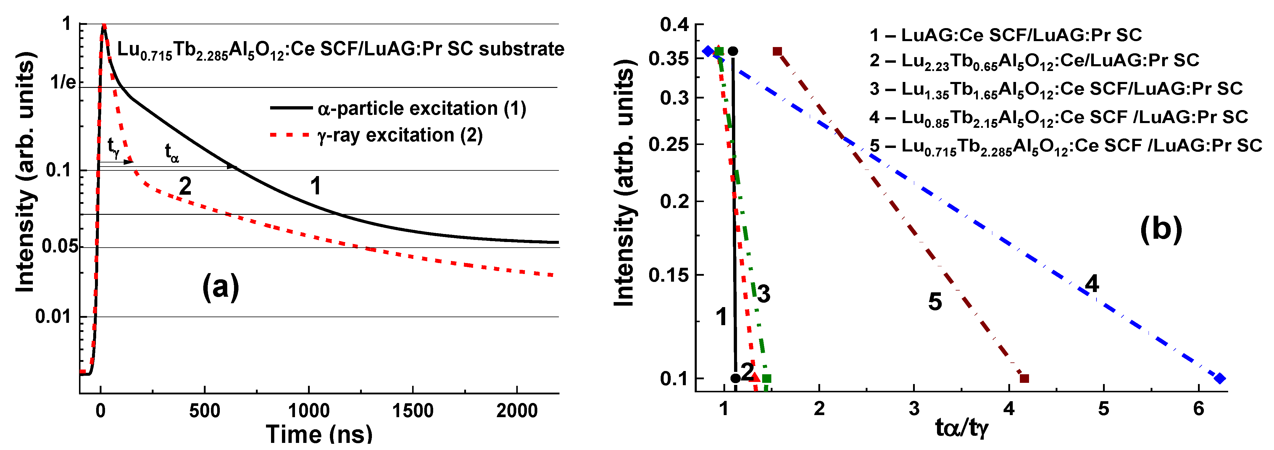
3.1.3. Composite Scintillator Based on LuAG:Pr Substrates
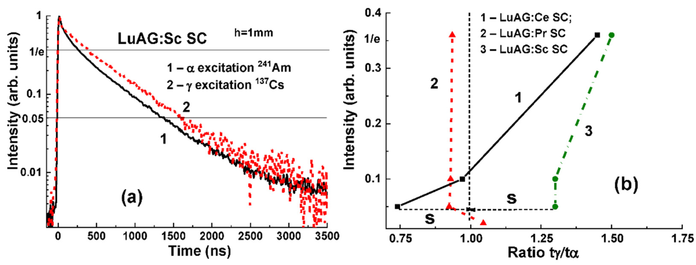
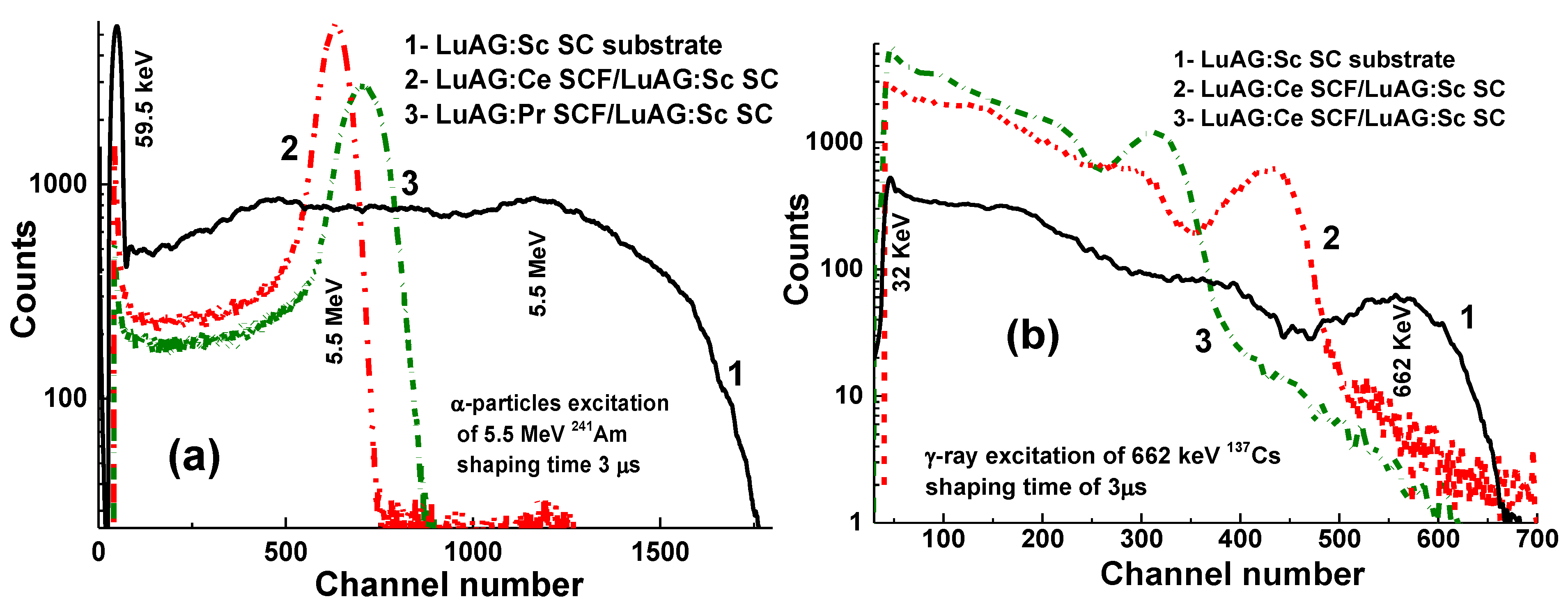
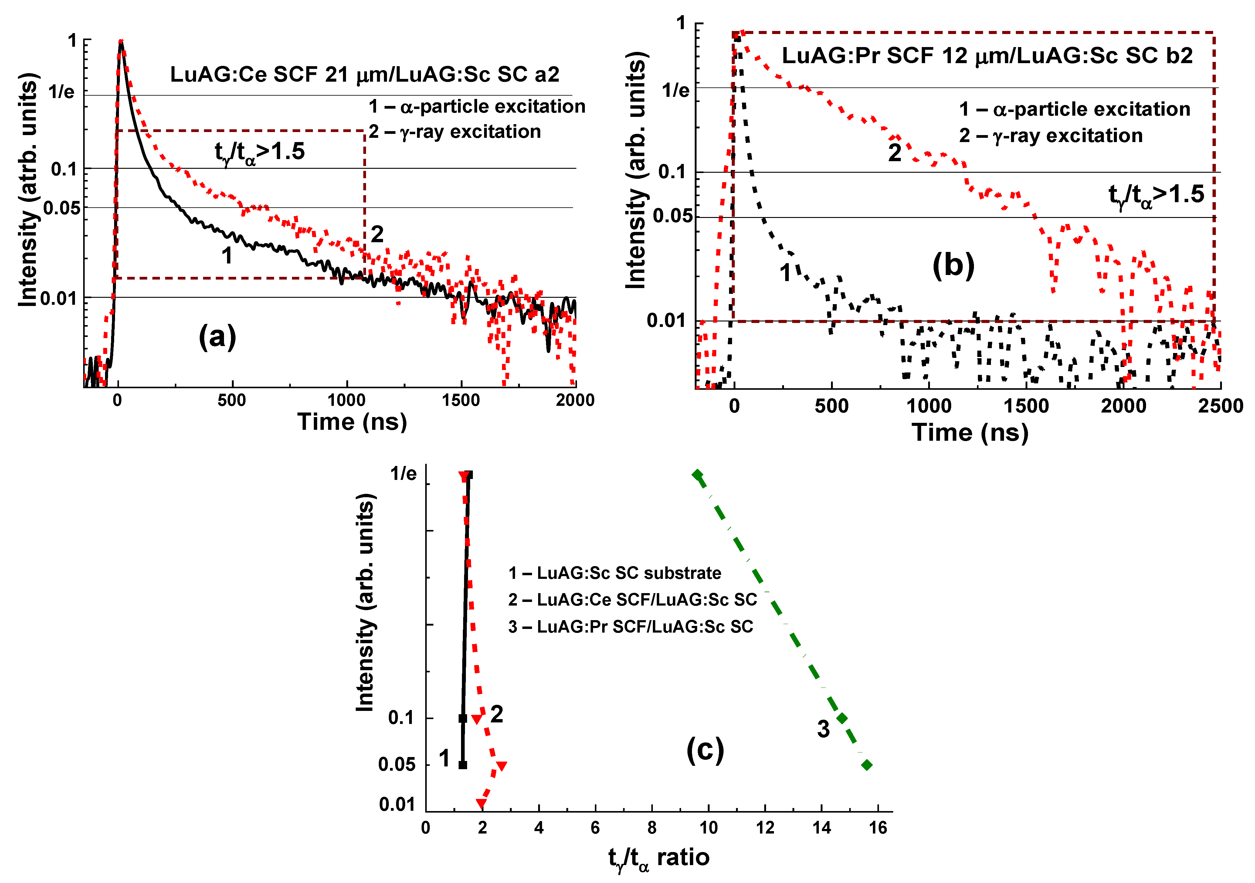
3.1.4. Composite Scintillators Based on LuAG:Sc Substrate
3.2. Composite Scintillators Based on Gd3Al2.5Ga2.5O12:Ce Substrates
3.2.1. Characterization of GAGG:Ce Substrates
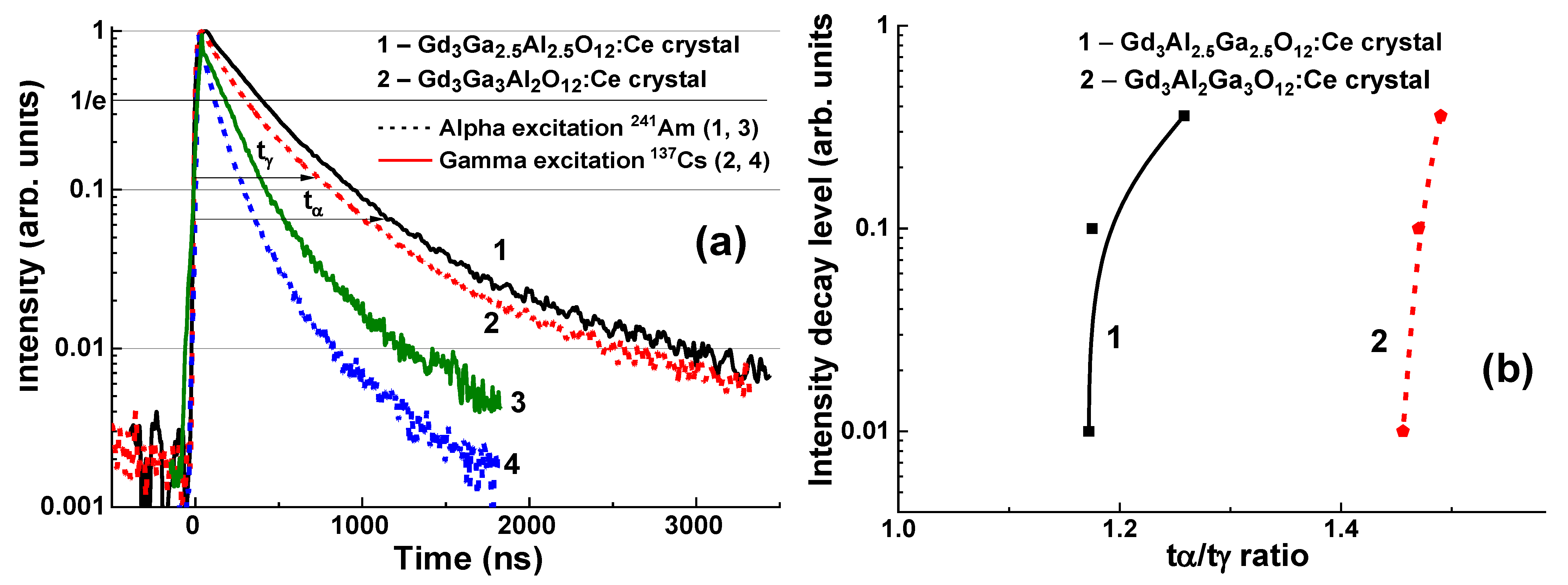
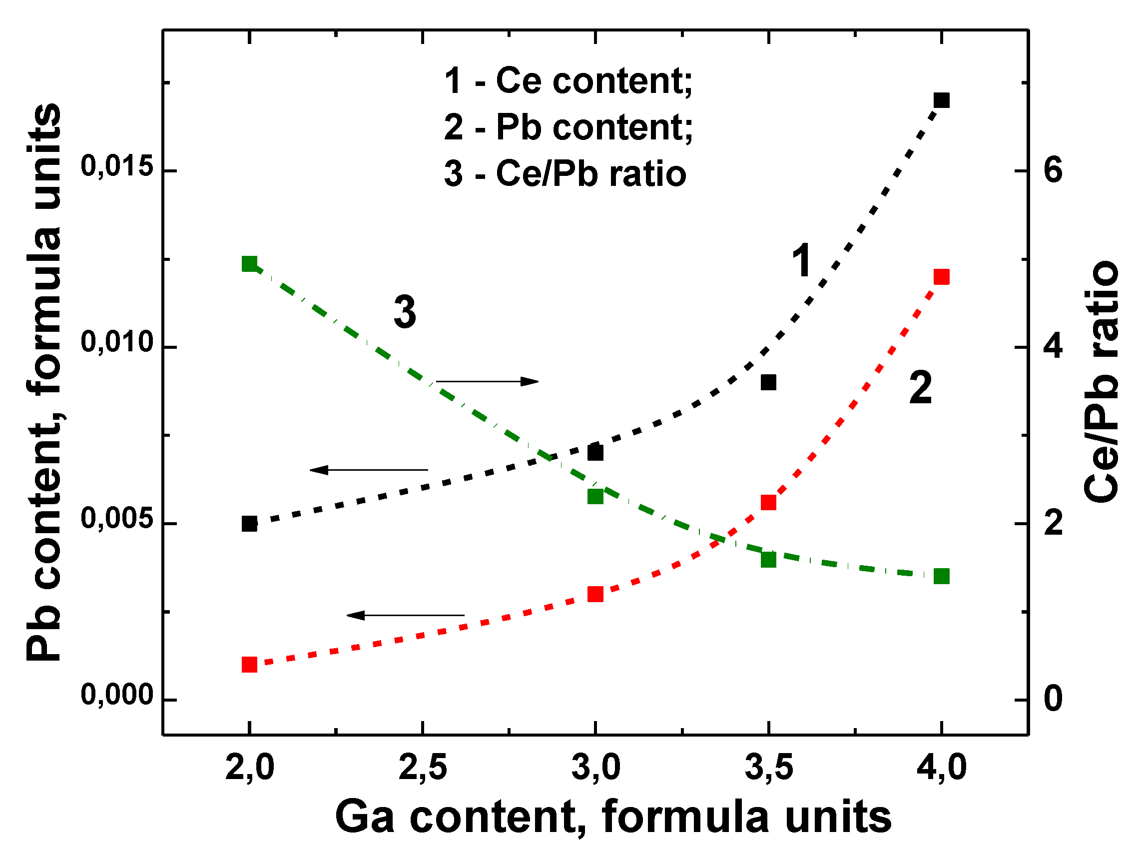
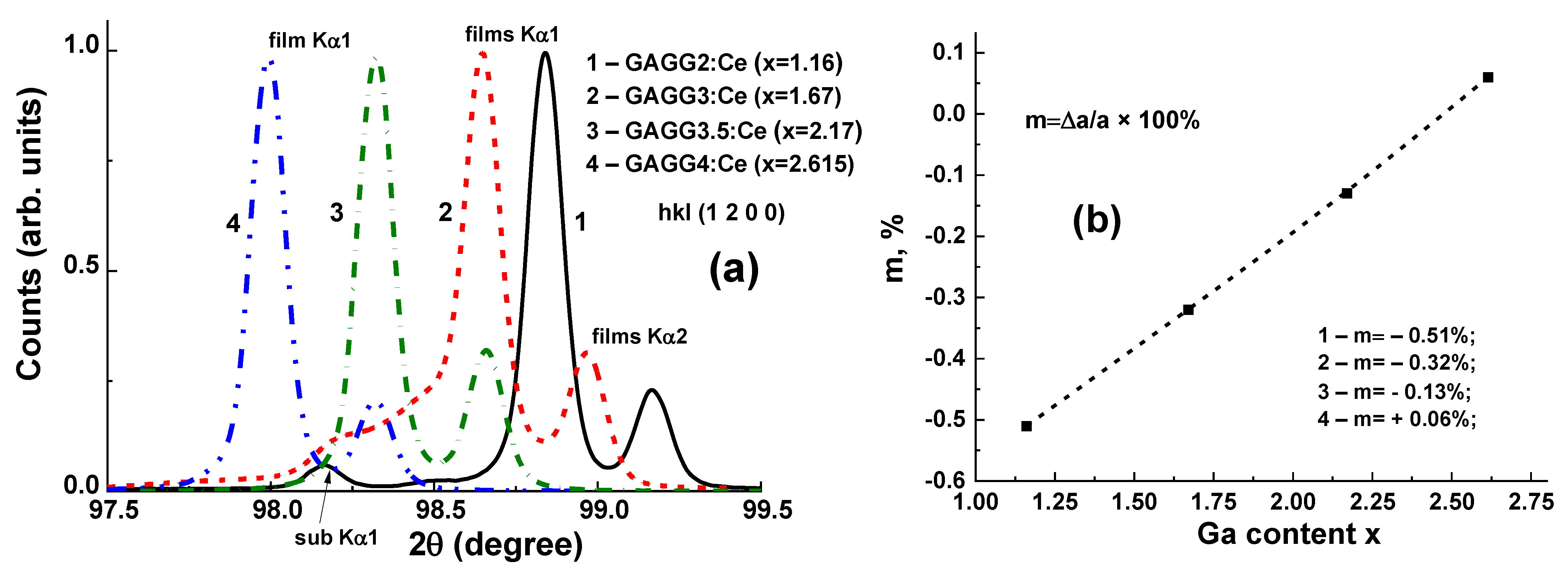
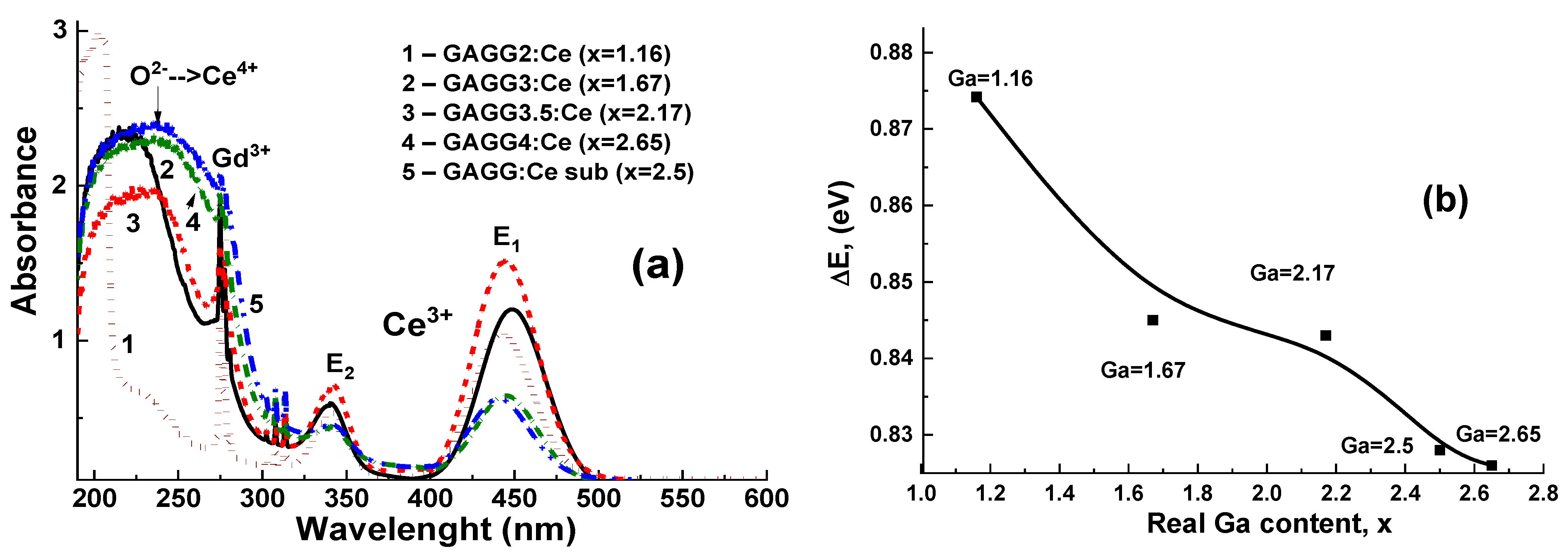
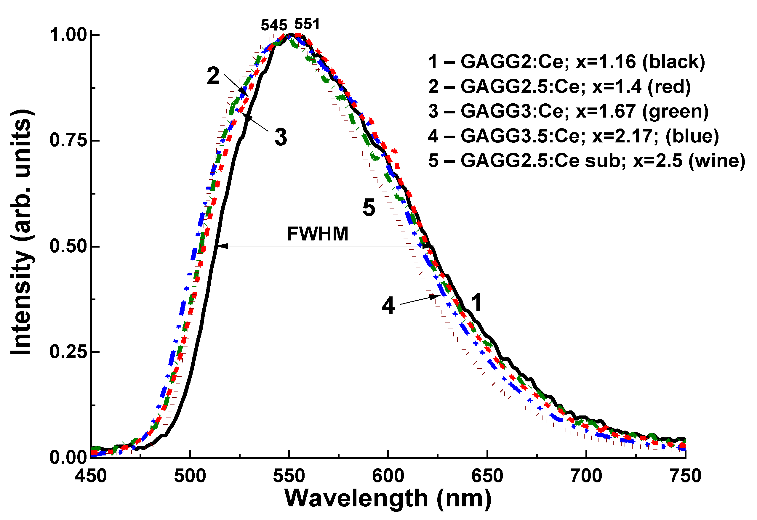
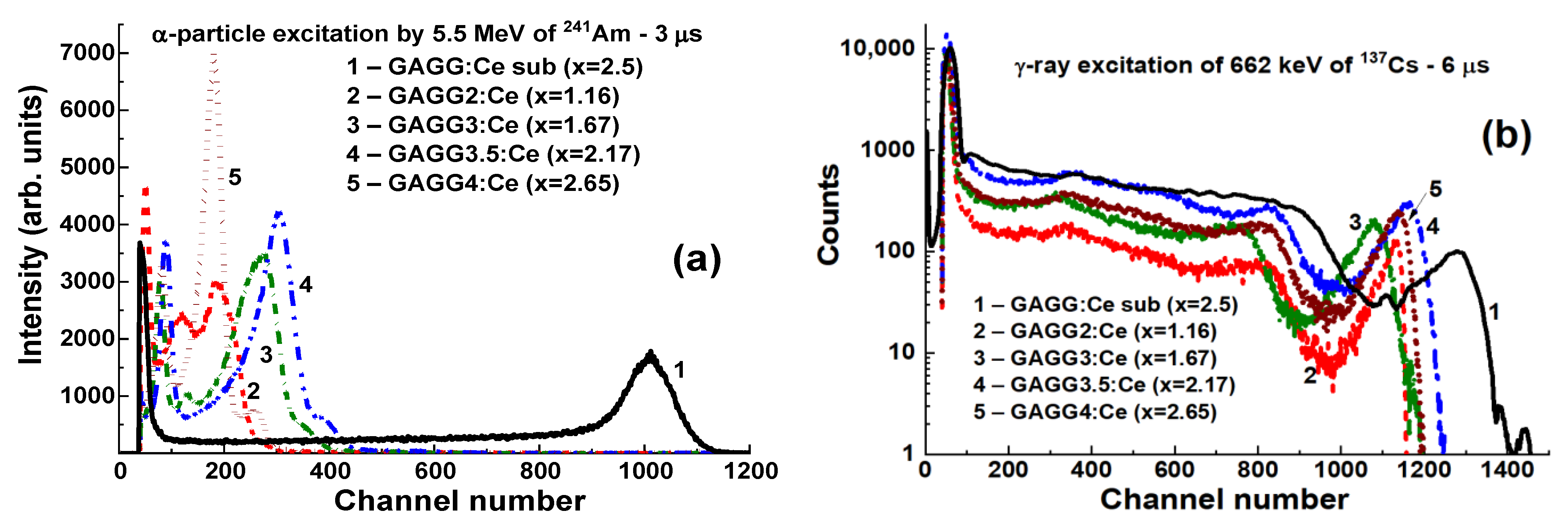
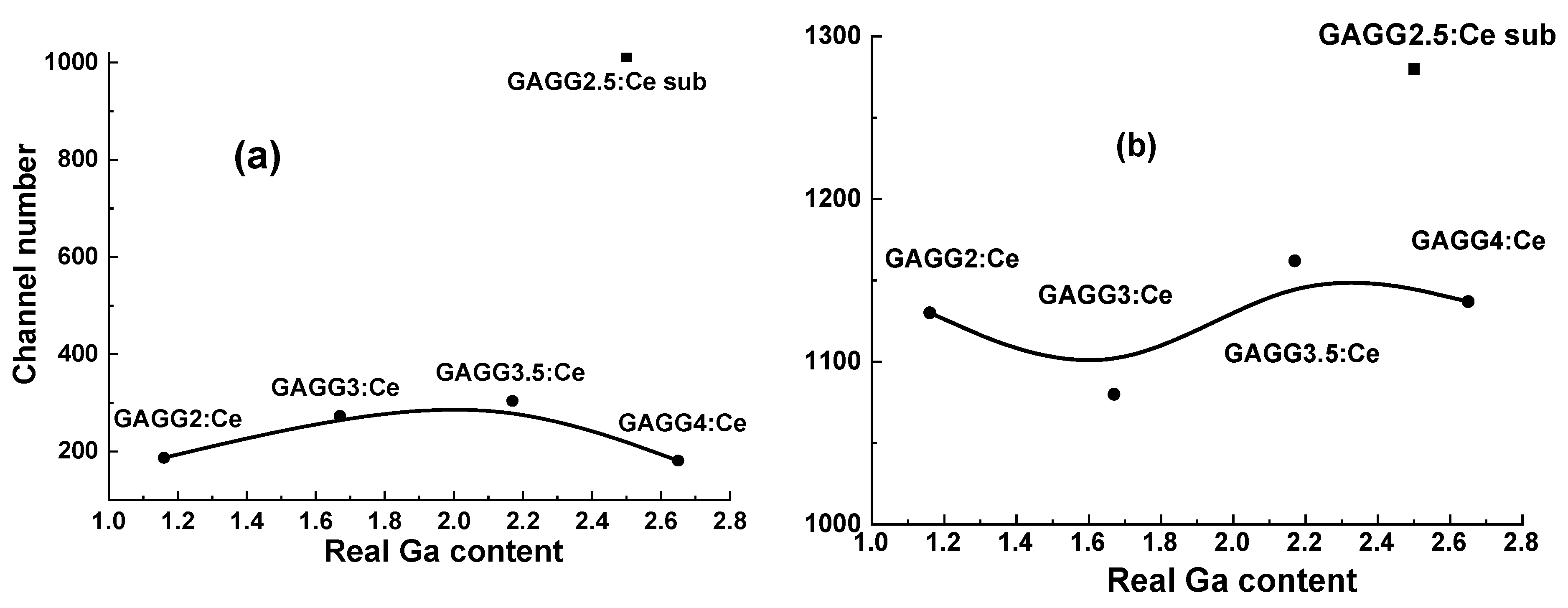
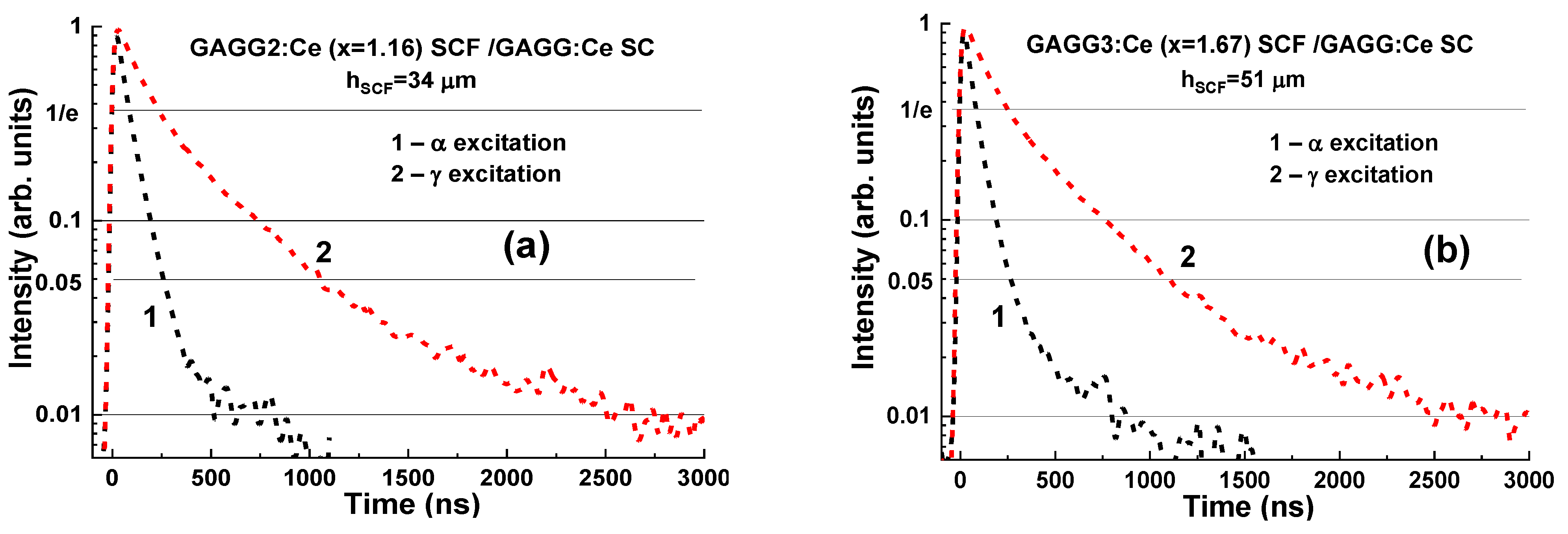
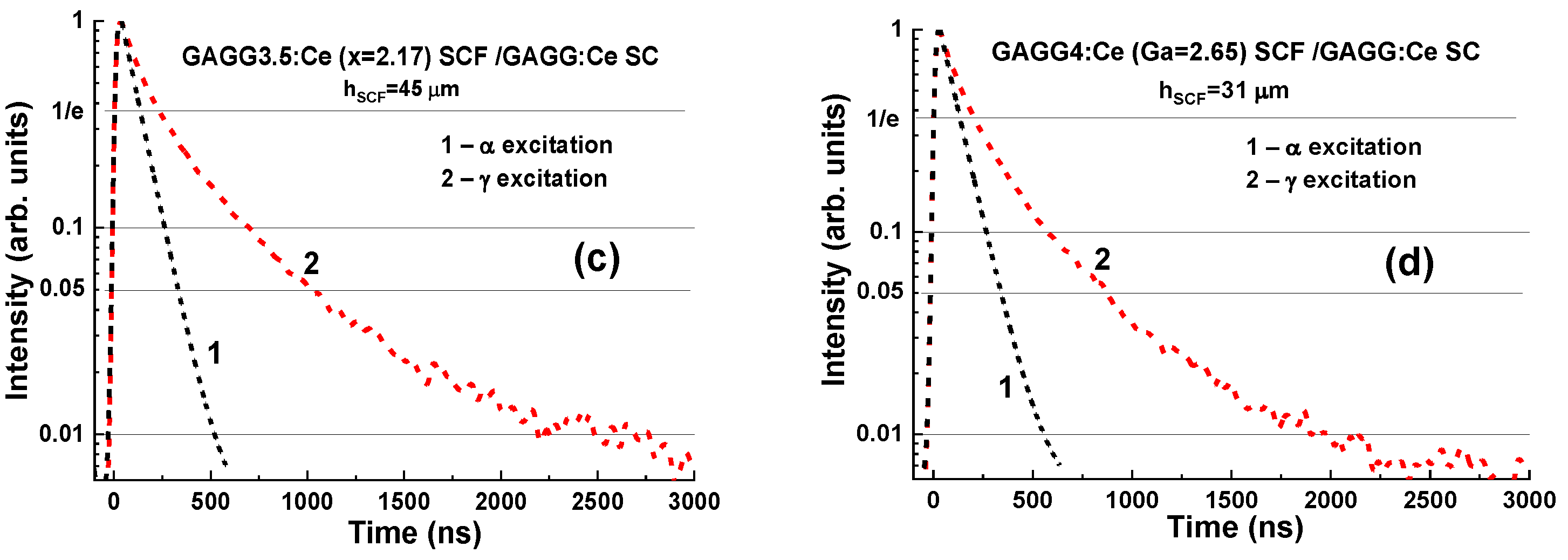
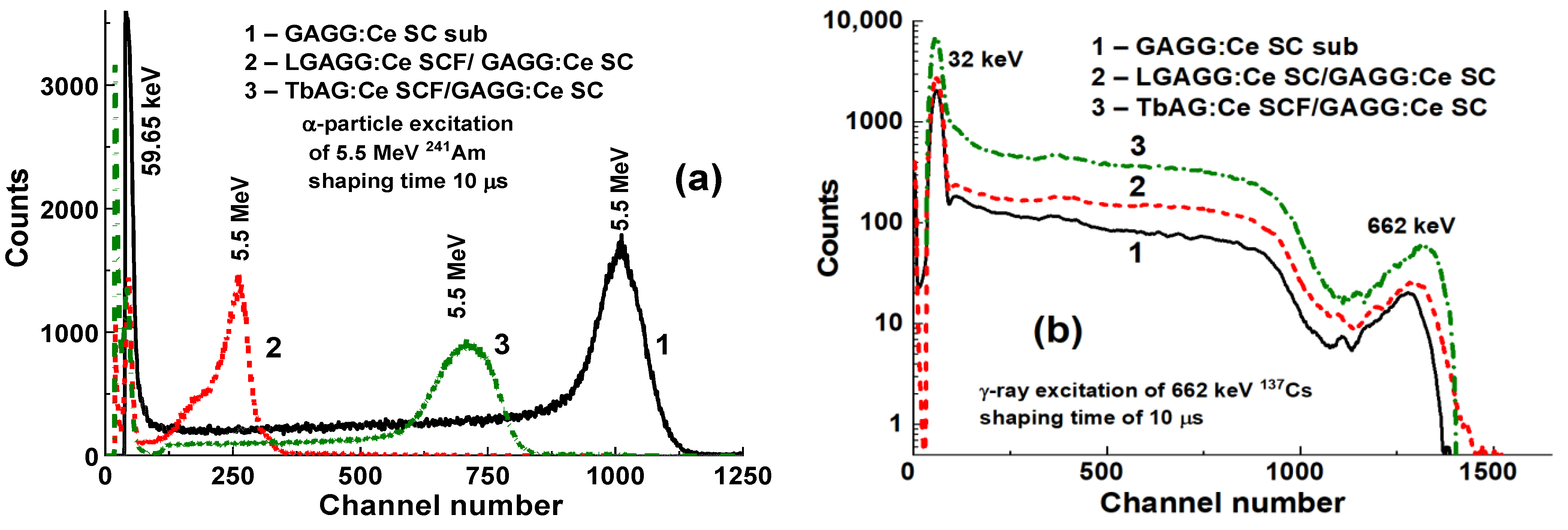
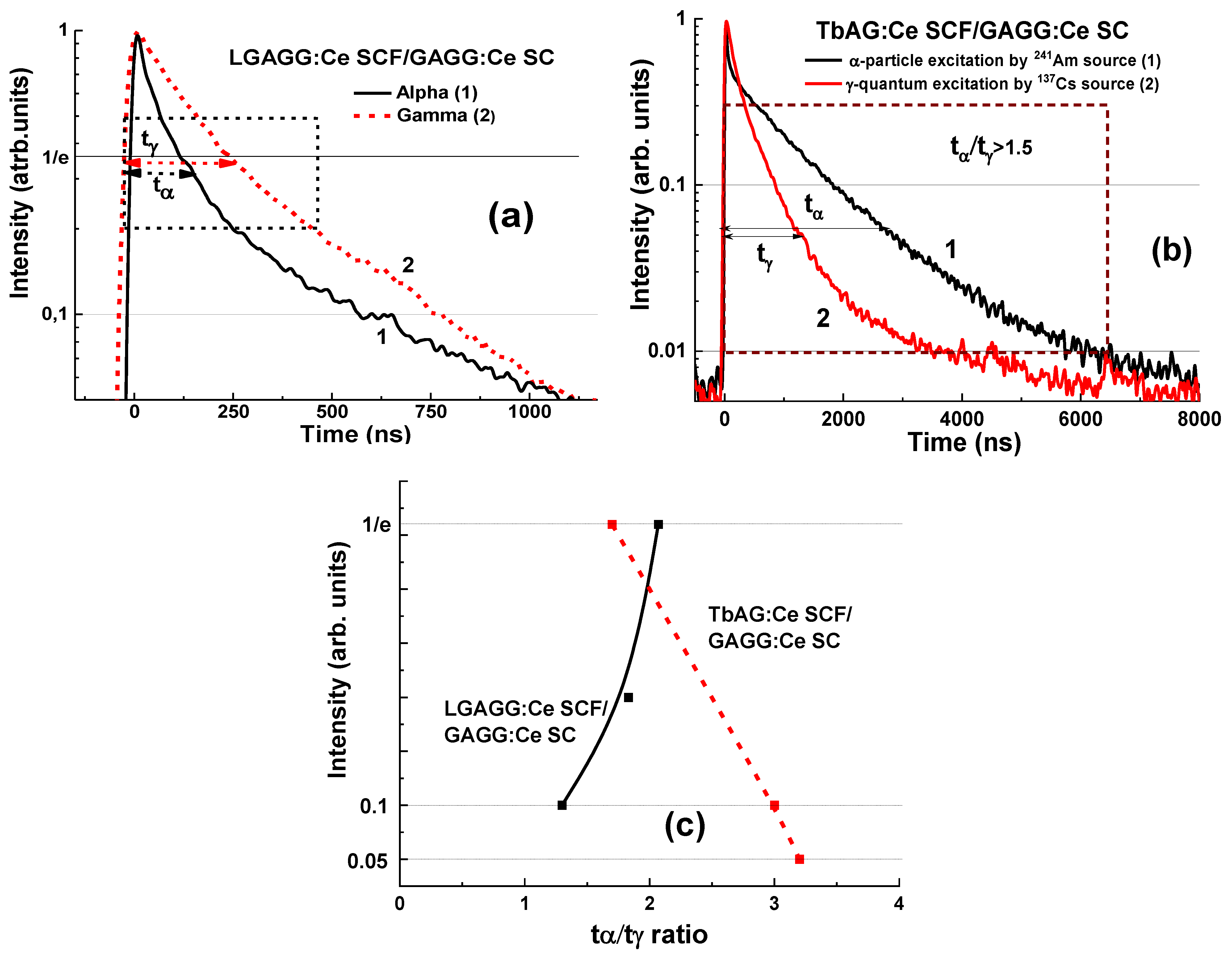
3.2.2. Composite Scintillators Based on the GAGG:Ce Crystals and SCF
3.2.3. Scintillating Screens Based on the LPE-Grown Ce3+-Doped Tb3Al5O12 and Tb3−xGdxAl5−yGayO12 Garnets
3.3. Composite TL Detectors
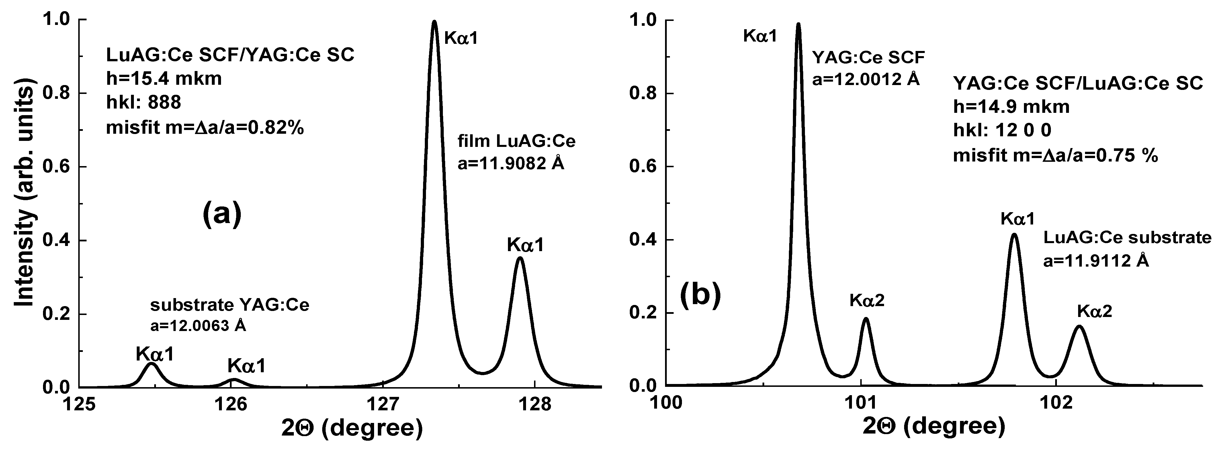
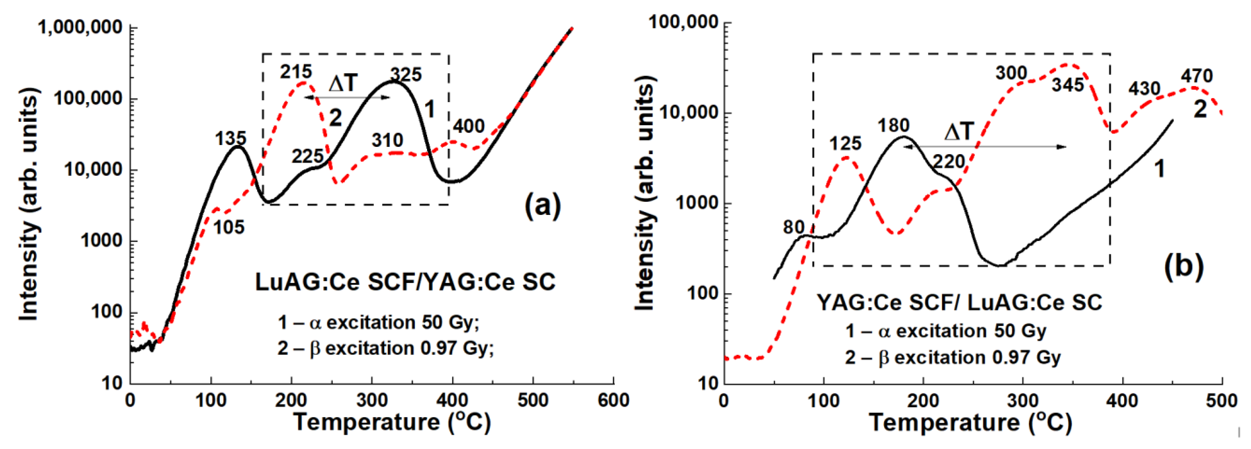
3.3.1. LuAG:Ce SCF/YAG:Ce and YAG:Ce SCF/LuAG:Ce SC Composite TL Materials
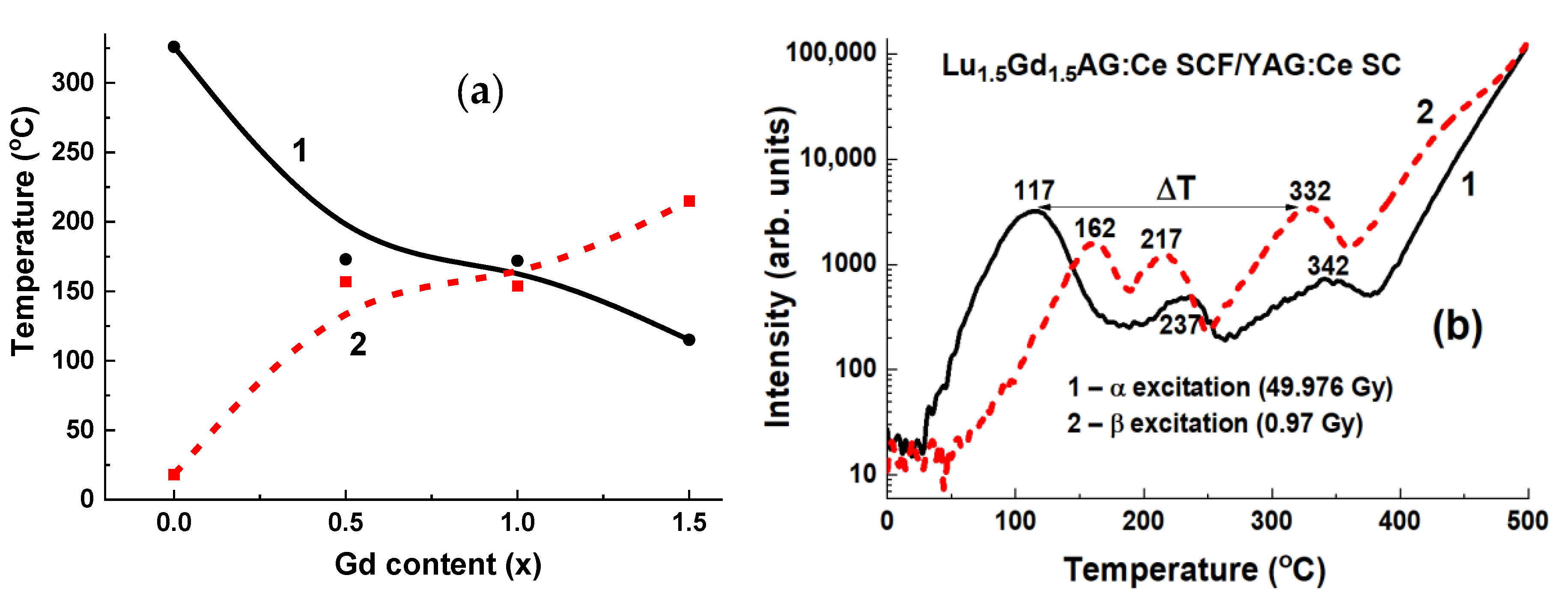
3.3.2. Lu3−xGdxAG:Ce SCF/YAG:Ce SC Composite TL Materials
4. Concluding Remarks
Author Contributions
Funding
Institutional Review Board Statement
Informed Consent Statement
Data Availability Statement
Acknowledgments
Conflicts of Interest
References
- Zorenko, Y.; Novosad, S.S.; Pashkovskii, M.V.; Lyskovich, A.B.; Savitskii, V.G.; Batenchuk, M.M.; Malyutenkov, P.S.; Patsagan, N.I.; Nazar, I.V.; Gorbenko, V.I. Epitaxial structures of garnets as scintillation detectors of ionizing radiation. J. Appl. Spectrosc. 1990, 52, 645–649. [Google Scholar] [CrossRef]
- Ferrand, B.; Chambazand, B.; Couchaud, M. Liquid phase epitaxy: A versatile technique for the development of miniature optical components in single crystal dielectric media. Opt. Mater. 1999, 11, 101–114. [Google Scholar] [CrossRef]
- Zazubovich, S.; Krasnikov, A.; Zorenko, Y.; Gorbenko, V.; Babin, V.; Mihokova, E.; Nikl, M. Nanocomposite, Ceramic, and Thin Film Scintillators; Pan Stanford Publishing Pte. Ltd.: Singapore, 2016; pp. 227–305. ISBN 978-981-4745-22-2. [Google Scholar]
- Robertson, J.M.; Van Tol, M.V. Cathodoluminescent garnet layers. Thin Solid Film. 1984, 114, 221–240. [Google Scholar] [CrossRef]
- Hrytskiv, Z.D.; Zorenko, Y.; Gorbenko, V.; Pedanand, A.D.; Shkliarsyi, V.I. Single crystalline film screens for cathode-ray tubes: New life of television scanning optical microscopy. Radiat. Meas. 2007, 42, 933–936. [Google Scholar] [CrossRef]
- Schauer, P.; Lalinský, O.; Kucera, M. Overview of S(T)EM electron detectors with garnet scintillators: Some potentials and limits. Microsc. Res. Tech. 2021, 84, 753–770. [Google Scholar] [CrossRef]
- Molva, E. Microchip lasers and their applications in optical microsystems. Opt. Mater. 1999, 11, 289–299. [Google Scholar] [CrossRef]
- Klimczak, M.; Malinowski, M.; Sarnecki, J.; Piramidowicz, R.J. Luminescence properties in the visible of Dy:YAG/YAG planar waveguides. Luminescence 2009, 129, 1869–1873. [Google Scholar] [CrossRef]
- Zorenko, Y.; Batenchuk, M.; Gorbenko, V.; Pashkovsky, M. Single-crystalline oxide films of the Al2O3-Y2O3-R2O3 system as optical sensors of various types of ionizing radiation: Significant advantages over volume analogs. Proc. SPIE 1997, 2967, 101. [Google Scholar] [CrossRef]
- Zorenko, Y.; Gorbenko, V.; Konstankevych, I.; Grinevand, B.; Globus, M. Scintillation properties of Lu3Al5O12:Ce single-crystalline films. Nucl. Instrum. Methods Phys. Res. 2002, 486, 309–314. [Google Scholar] [CrossRef]
- Koch, A.; Raven, C.; Spanne, P.; Snigirev, A. X-ray imaging with submicrometer resolution employing transparent luminescent screens. J. Opt. Soc. Amer. A Opt. 1998, 15, 1940–1951. [Google Scholar] [CrossRef] [Green Version]
- Martin, T.; Koch, A. Recent developments in X-ray imaging with micrometer spatial resolution. J. Synchrotron Radiat. 2006, 13, 180–194. [Google Scholar] [CrossRef] [Green Version]
- Zorenko, Y.; Gorbenko, V.; Konstankevych, I.; Pashkovsky, M.; Globus, M.; Grinyov, B.; Tarasov, V.; Dorenbos, P.; Van Eijk, C.; Van Loef, E. Scintillators on the base of single crystalline films of Al2O3-Y2O3 system oxides. In Proceedings of the 5th International Conference on Inorganic Scintillators and Their Applications, Moscow State University, Moscow, Russia, 6–20 August 1999; pp. 476–481, ISBN 582790079. [Google Scholar]
- Globus, M.; Grinyov, B.; Ratner, M.; Tarasov, V.; Lyubinskiy, V.; Vydai, Y.; Ananenko, A.; Zorenko, Y.; Gorbenko, V.; Konstankevych, I. New type of scintillation detectors for biological, medical, and radiation monitoring applications. IEEE Trans. Nucl. Sci. 2004, 51, 1297–1303. [Google Scholar] [CrossRef]
- Witkiewicz-Lukaszek, S.; Gorbenko, V.; Zorenko, T.; Paprocki, K.; Sidletskiy, O.; Gerasymov, I.; Mares, J.A.; Kucerkova, R.; Nikl, M.; Zorenko, Y. Novel all-solid-state composite scintillators based on the epitaxial structures of LuAG garnet doped with Pr, Sc and Ce ions. IEEE Trans. Nucl. Sci. 2018, 65, 2114–2119. [Google Scholar] [CrossRef]
- Witkiewicz-Lukaszek, S.; Gorbenko, V.; Zorenko, T.; Paprocki, K.; Sidletskiy, O.; Gerasymov, I.; Mares, J.A.; Kucerkova, R.; Nikl, M.; Zorenko, Y. Composite scintillators based on the crystals and single crystalline films of LuAG garnet doped with Ce3+, Pr3+ and Sc3+ ions. Opt. Mater. 2018, 84, 593–599. [Google Scholar] [CrossRef]
- Mares, J.A.; Witkiewicz-Lukaszek, S.; Gorbenko, V.; Zorenko, T.; Kucerkova, R.; Beitlerova, A.; D′Ambrosio, C.; Dlouhy, J.; Nikl, M.; Zorenko, Y. Alpha and gamma spectroscopy of Composite scintillators based on the LuAG:Pr crystals and single crystalline films of LuAG:Ce and (Lu,Gd,Tb)AG:Ce garnets. Opt. Mater. 2019, 96, 109268. [Google Scholar] [CrossRef]
- Witkiewicz-Lukaszek, S.; Gorbenko, V.; Zorenko, T.; Sidletskiy, O.; Arhipov, P.; Fedorov, A.; Mares, J.A.; Kucerkova, R.; Nikl, M. Liquid phase epitaxy growth of high-performance composite scintillators based on single crystalline films and crystals of LuAG. CrystEngComm 2020, 22, 3713–3724. [Google Scholar] [CrossRef]
- Gorbenko, V.; Witkiewicz-Lukaszek, S.; Zorenko, T.; Syrotych, Y.; Mares, J.A.; Kucerkova, R.; Nikl, M.; Sidletskiy, O.; Fedorov, A.; Zorenko, Y. Development of composite scintillators based on the LuAG:Pr single crystalline films FILMS and LuAG:Sc single crystals. Crystals 2021, 11, 846. [Google Scholar] [CrossRef]
- Witkiewicz-Lukaszek, S.; Gorbenko, V.; Zorenko, T.; Sidletskiy, O.; Gerasymov, I.; Fedorov, A.; Yoshikawa, A.; Mares, J.A.; Nikl, M.; Zorenko, Y. Development of composite scintillators Based on single crystalline films and Crystals of Ce3+-Doped (Lu,Gd)3(Al, Ga)5O12 Mixed Garnet Compounds. Cryst. Growth Des. 2018, 18, 1834–1842. [Google Scholar] [CrossRef]
- Witkiewicz-Lukaszek, S.; Gorbenko, V.; Zorenko, T.; Paprocki, K.; Sidletskiy, O.; Fedorov, A.; Kucerkova, R.; Mares, J.A.; Nikl, M.; Zorenko, Y. Epitaxial growth of composite scintillators based on Tb3Al5O12:Ce single crystalline films and Gd3Al2.5Ga2.5O12:Ce crystal substrates. CrystEngComm 2018, 20, 3994–4002. [Google Scholar] [CrossRef]
- Witkiewicz-Lukaszek, S.; Gorbenko, V.; Zorenko, T.; Syrotych, Y.; Kucerkova, R.; Mares, J.A.; Nikl, M.; Sidletskiy, O.; Fedorov, A.; Kurosawa, S.; et al. New types of composite scintillators based on the single crystalline films and crystals of Gd3(Al,Ga)5O12:Ce mixed garnets. Mater. Sci. Eng. B 2021, 264, 114909. [Google Scholar] [CrossRef]
- Witkiewicz-Lukaszek, S.; Gorbenko, V.; Bilski, P.; Mrozik, A.; Zorenko, T.; Fedorov, A.; Zorenko, Y. LPE growth of composite thermoluminescent detectors based on the Lu3−xGdxAl5O12: Single crystalline films and YAG:Ce crystals. Crystals 2020, 10, 189. [Google Scholar] [CrossRef] [Green Version]
- Witkiewicz-Lukaszek, S.; Gorbenko, V.; Zorenko, T.; Zorenko, Y.; Gieszczyk, W.; Mrozik, A.; Bilski, P. Composite thermoluminescent detectors based on the Ce3+ doped LuAG/YAG and YAG/LuAG epitaxial structures. Radiat. Meas. 2019, 128, 106124. [Google Scholar] [CrossRef]
- Zorenko, Y.; Gorbenko, V.; Savchyn, V.; Fedorov, A.; Kuklinski, B.; Grinberg, M.; Bilski, P.; Gieszczyk, W.; Twardak, A.; Mandowski, A.; et al. Luminescent properties of YAlO3:Mn single crystalline films. Opt. Mater. 2012, 34, 1979–1983. [Google Scholar] [CrossRef]
- Gieszczyk, W.; Bilski, P.; Kłosowski, M.; Mrozik, A.; Zorenko, Y.; Zorenko, T.; Paprocki, K. Luminescent properties of undoped and Ce3+ doped crystals in Y2O3–Lu2O3-Al2O3 triple oxide system grown by micro-pulling-down method. Opt. Mater. 2019, 89, 408–413. [Google Scholar] [CrossRef]
- Zorenko, Y.; Gorbenko, V. Growth peculiarities of the R3Al5O12 (R= Lu, Yb, Tb, Eu-Y) single crystalline film phosphors by Liquid Phase Epitaxy. Radiat. Meas. 2007, 42, 907–910. [Google Scholar] [CrossRef]
- Gorbenko, V.; Zorenko, T.; Pawlowski, P.; Iskaliyeva, A.; Paprocki, K.; Suchocki, A.; Zhydachevskii, Y.; Fedorov, A.; Khaidukov, N.; Van Deun, R.; et al. Luminescent and scintillation properties of Ce3+ doped Ca2RMgScSi3O12 (R=Y, Lu) single crystalline films. J. Lumin. 2018, 195, 362–370. [Google Scholar] [CrossRef]
- Zorenko, Y.; Gorbenko, V.; Witkiewicz, S.; Zorenko, Y. Luminescent properties of (La,Lu,Gd)3(Al,Sc,Ga)5O12:Ce mixed garnets under synchrotron radiation excitation. J. Lumin. 2018, 199, 483–487. [Google Scholar] [CrossRef]
- Chen, R.; Pagonis, V. (Eds.) Advances in Physics and Applications of Optically and Thermally Stimulated Luminescence; World Scientific, WSPC (Europe): Singapore, 19 March 2019; pp. 285–317. [Google Scholar] [CrossRef]
- Yukihara, E.; Kron, T. Thermoluminescence dosimetry (TLD) in medicine: Five ‘w’s and one how. Radiat. Prot. Dosim. 2020, 192, 139–151. [Google Scholar] [CrossRef]
- Bilski, P. Lithium Fluoride: From LiF:Mg,Ti to LiF:Mg,Cu,P. Radiat. Prot. Dosim. 2002, 100, 199–203. [Google Scholar] [CrossRef]
- Horowitz, Y.S. Thermoluminescence dosimetry: State-of-the-art and frontiers of future research. Radiat. Meas. 2014, 71, 2–7. [Google Scholar] [CrossRef]
- Bilski, P.; Olko, P.; Burgkhardt, B.; Piesch, E. Ultra-Thin LiF:Mg,Cu,P Detectors for Beta Dosimetry. Radiat. Meas. 1995, 24, 439–443. [Google Scholar] [CrossRef]
- Bilski, P.; Budzanowski, M.; Olko, P.; Christensen, P. Properties of Different Thin-Layer LiF:Mg,Cu,P TL Detectors for Beta Dosimetry. Radiat. Prot. Dosim. 1996, 66, 101–104. [Google Scholar] [CrossRef]
- Bueno, M.; Carrasco, P.; Jornet, N.; Munoz-Montplet, C.; Duch, M.A. On the suitability of ultrathin detectors for absorbed dose assessment in the presence of high-density heterogeneities. Med. Phys. 2014, 41, 142–153. [Google Scholar] [CrossRef] [PubMed]
- Grassi, E.; Sghedoni, R.; Piccagli, V.; Fioroni, F.; Borasi, G.; Iori, M. Comparison of two different types of LiF:Mg,Cu,P thermoluminescent dosimeters for detection of beta rays (beta-TLDs) from Sr-90/Y-90, K-85 and Pm-147 sources. Health Phys. 2011, 100, 515–522. [Google Scholar] [CrossRef]
- Goksu, H.Y.; Bulur, E.; Wahl, W. Beta dosimetry using thin-layer alpha-Al2O3:C TL detectors. Radiat. Prot. Dosim. 1999, 84, 451–455. [Google Scholar] [CrossRef]
- Twardak, A.; Bilski, P.; Zorenko, Y.; Gorbenko, V.; Mandowski, A.; Mandowska, E.; Sidletskiy, O. Comparative study of TSL and OSL properties of LSO and LSO:Ce single crystals and single crystalline films. Radiat. Meas. 2013, 56, 196–199. [Google Scholar] [CrossRef]
- Nikl, M.; Tous, T.; Mares, J.A.; Prusa, P.; Mihokova, E.; Blazek, K.; Vedda, A.; Zorenko, Y.; Gorbenko, V.; Babin, V. Lu3Al5O12-based materials for high 2D-resolution scintillation detectors. Proc. SPIE 2009, 7310, 731008. [Google Scholar] [CrossRef]
- Nikl, M.; Yoshikawa, A.; Kamada, K.; Stanek, C.R.; Blazek, K. Development of LuAG-based scintillator crystals—A review. Prog. Cryst. Growth Charact. Mater. 2013, 59, 47–72. [Google Scholar] [CrossRef]
- Kamada, K.; Yanagida, T.; Pejchal, J.; Nikl, M.; Endo, T.; Tsutsumi, K.; Fujimoto, Y.; Fukabori, A.; Yoshikawa, A. Crystal growth and scintillation properties of Ce doped Gd3Al2Ga3O12 single crystals. IEEE Trans. Nucl. Sci. 2012, 59, 2112–2115. [Google Scholar] [CrossRef]
- Crytur. Integrated Crystal Based Solutions. Available online: www.crytur.cz (accessed on 24 November 2021).
- Advatech—Radiation Detection/Imaging and Photonics. Available online: www.advatech-uk.co.uk (accessed on 24 November 2021).
- Vrubel, I.; Polozkov, R.; Shelykh, I.; Khanin, V.; Rodnyi, P.; Ronda, C. Bandgap Engineering in Yttrium−Aluminum Garnet with Ga Doping. Cryst. Growth Des. 2017, 17, 1863–1869. [Google Scholar] [CrossRef]
- Li, M.; Meng, M.; Chen, J.; Sun, Y.; Cheng, G.; Chen, L.; Zhao, S.; Wan, B.; Feng, H.; Ren, G.; et al. Abnormal Site Preference of Al and Ga in Gd3Al2.3Ga2.7O12:Ce. Phys. Status Solidi B 2021, 258, 2000603. [Google Scholar] [CrossRef]
- Nargelas, S.; Talochka, Y.; Vaitkevicius, A.; Dosovitskiy, G.; Buzanov, O.; Vasil’ev, A.; Malinauskas, T.; Korzhik, M.; Tamulaitis, G. Influence of matrix composition and its fluctuations on excitation relaxation and emission spectrum of Ce ions in (GdxY1-x)3 Al2Ga3O12:Ce scintillators. J. Lumin. 2022, 242, 118590. [Google Scholar] [CrossRef]
- Khanin, V.; Venevtsev, I.; Chernenko, K.; Pankratov, V.; Klementiev, K.; van Swieten, T.; van Bunningen, A.J.; Vrubel, I.; Shendrik, R.; Ronda, C.; et al. Exciton interaction with Ce3+ and Ce4+ ions in (LuGd)3(Ga,Al)5O12 ceramics. J. Lumin. 2021, 237, 118150. [Google Scholar] [CrossRef]
- Korzhik, M.; Alenkov, V.; Buzanov, O.; Dosovitskiy, G.; Fedorov, A.; Kozlov, D.; Mechinsky, V.; Nargelas, S.; Tamulaitis, G.; Vaitkevičius, A. Engineering of a new single-crystal multi-ionic fast and high-light-yield scintillation material (Gd0.5–Y0.5)3Al2Ga3O12:Ce,Mg. CrystEngComm 2020, 22, 2502–2506. [Google Scholar] [CrossRef]
- Pankratova, V.; Kozlova, A.; Buzanov, O.; Chernenko, K.; Shendrik, R.; Šarakovskis, A.; Pankratov, V. Time-resolved luminescence and excitation spectroscopy of Co-doped Gd3Ga3Al2O12 scintillating crystals. Sci. Rep. 2020, 10, 20388. [Google Scholar] [CrossRef]
- Dantelle, G.; Boulon, G.; Guyot, Y.; Testemale, D.; Guzik, M.; Kurosawa, S.; Kamada, K.; Yoshikawa, A. Research on Efficient Fast Scintillators: Evidence and X-Ray Absorption Near Edge Spectroscopy Characterization of Ce4+ in Ce3+, Mg2+-Co-Doped Gd3Al2Ga3O12 Garnet Crystal. Phys. Status Solidi B 2019, 257, 1900510. [Google Scholar] [CrossRef]
- Bárta, J.; Pestovich, K.S.; Valdez, J.A.; Wiggins, B.W.; Richards, C.; Smith, E.; Clayton, J.H.; Smalley, D.; McClellan, K.J. Compositional screening of Ce-doped (Gd,Lu,Y)3(Al,Ga)5O12 ceramics prepared by quenching from melt and their luminescence properties. J. Alloys Compd. 2021, 889, 161687. [Google Scholar] [CrossRef]
- Nakauchi, D.; Okada, G.; Kawano, N.; Kawaguchi, N.; Yanagida, T. Effects of Ga substitution in Ce:Tb3GaxAl5%xO12 single crystals for scintillator applications. Jpn. J. Appl. Phys. 2018, 57, 02CB02. [Google Scholar] [CrossRef]
- Boyarintseva, Y.; Neicheva, S.; Zhmurin, P.; Arhipov, P.; Gerasymov, I.; Tkachenko, S.; Sidletskiy, O.; Baumer, V.; Vovk, O.; Nizhankovskyi, S. Optical study of Y3-xGdxAl5O12:Ce crystals grown from the melt. Opt. Mater. 2019, 96, 109283. [Google Scholar] [CrossRef]
- Gerasymov, I.; Nepokupnaya, T.; Boyarintsev, A.; Sidletskiy, O.; Kurtsev, D.; Voloshyna, O.; Trubaieva, O.; Boyarintseva, Y.; Sibilieva, T.; Shaposhnyk, A.; et al. GAGG:Ce composite scintillator for X-ray imaging. Opt. Mater. 2020, 109, 110305. [Google Scholar] [CrossRef]
- Nikl, M.; Mihokova, E.; Pejchal, J.; Vedda, A.; Zorenko, Y.; Nejezchleb, K. The antisite LuAl defect-related trap in Lu3Al5O12:Ce single crystal. Phys. Status Solidi B 2005, 242, 119–121. [Google Scholar] [CrossRef]
- Fasoli, M.; Vedda, A.; Nikl, M.; Jiang, C.; Uberuaga, B.; Andersson, D.A.; McClellan, K.J.; Stanek, C.R. Band-gap engineering for removing shallow traps in rare-earth Lu3Al5O12 garnet scintillators using Ga3+ doping. Phys. Rev. B 2011, 84, 081102(R). [Google Scholar] [CrossRef] [Green Version]
- Nikl, M.; Yoshikawa, A. Recent R&D Trends in Inorganic Single-Crystal Scintillator Materials for Radiation Detection. Adv. Opt. Mater. 2015, 3, 463–481. [Google Scholar] [CrossRef]
- Zorenko, Y.; Gorbenko, V.; Savchyn, V.; Zorenko, T.; Fedorov, A.; Wrzesiński, H.; Vasylkiv, Y. Multi-component Ce doped (Gd,Y,La,Lu)3(Al,Ga,Sc)5O12 garnets—A new story in the development of scintillating single crystalline film screens. Radiat. Meas. 2013, 56, 150–154. [Google Scholar] [CrossRef]
- Zorenko, Y.; Gorbenko, V.; Savchyn, V.; Zorenko, T.; Fedorov, A.; Sidletskiy, O. Development of scintillating screens based on the single crystalline films of Ce doped (Gd,Y)3(Al,Ga,Sc)5O12 multicomponent garnets. J. Cryst. Growth 2014, 401, 532–536. [Google Scholar] [CrossRef]
- Prusa, P.; Kucera, M.; Mares, J.A.; Hanus, M.; Beitlerova, A.; Onderisinova, Z.; Nikl, M. Scintillation properties of the Ce-doped multicomponent garnet epitaxial films. Opt. Mater. 2013, 35, 2444–2448. [Google Scholar] [CrossRef]
- Zorenko, Y.; Gorbenko, V.; Vasylkiv, J.; Zelenyj, A.; Fedorov, A.; Kucerkova, R.; Mares, J.A.; Nikl, M.; Bilski, P.; Twardak, A. Growth and luminescent properties of scintillators based on the single crystalline films of Lu3−xGdxAl5O12:Ce garnet. Mater. Res. Bull. 2015, 64, 355–363. [Google Scholar] [CrossRef]
- Zorenko, Y.; Gorbenko, V.; Vasylkiv, J.; Strzyzewski, T.; Fedorov, A.; Kucerkova, R.; Mares, J.A.; Nikl, M.; Bilski, P.; Twardak, A. Growth and luminescent properties of scintillators based on the single crystalline films of (Lu,Gd)3(Al,Ga)5O12:Ce garnets. J. Lumin. 2016, 169, 828–837. [Google Scholar] [CrossRef]
- Zorenko, Y.; Gorbenko, V.; Zorenko, T.; Sidletskiy, O.; Fedorov, A.; Bilski, P.; Twardak, A.; Bilski, P. High-perfomance Ce-doped multicomponent garnet single crystalline film scintillators. Phys. Status Solidi RRL 2015, 9, 489–493. [Google Scholar] [CrossRef]
- Prusa, P.; Kucera, M.; Mares, J.A.; Onderisinova, Z.; Hanus, M.; Babin, V.; Beitlerova, A.; Nikl, M. Composition Tailoring in Ce-Doped Multicomponent Garnet Epitaxial Film Scintillators. Cryst. Growth Des. 2015, 15, 3715–3723. [Google Scholar] [CrossRef]
- Zorenko, Y.; Gorbenko, V.; Zorenko, T.; Paprocki, K.; Nikl, M.; Mares, J.A.; Bilski, P.; Twardak, A.; Sidletskiy, O.; Gerasymov, I.; et al. Scintillating screens based on the single crystalline films of multicomponent garnets: New achievements and possibilities. IEEE Trans. Nucl. Sci. 2016, 63, 497–502. [Google Scholar] [CrossRef]
- Zorenko, Y.; Gorbenko, V.; Zorenko, T.; Paprocki, K.; Bilski, P.; Twardak, A.; Voznyak, T.; Sidletskiy, O.; Gerasimov, Y.; Gryniov, B.; et al. Composition engineering of single crystalline films based on the multicomponent garnet compounds. Opt. Mater. 2016, 61, 3–10. [Google Scholar] [CrossRef]
- Zorenko, Y.; Douissard, P.; Martin, T.; Riva, F.; Gorbenko, V.; Zorenko, T.; Paprocki, K.; Iskalieva, A.; Witkiewicz, S.; Fedorov, A.; et al. Scintillating screens based on the LPE grown Tb3Al5O12:Ce single crystalline films. Opt. Mater. 2017, 65, 73–81. [Google Scholar] [CrossRef]
- Gorbenko, V.; Zorenko, T.; Witkiewicz, S.; Paprocki, K.; Sidletskiy, O.; Fedorov, A.; Bilski, P.; Twardak, A.; Zorenko, Y. LPE growth of single crystalline film scintillators based on Ce3+ Doped Tb3−xGdxAl5−yGayO12 mixed garnets. Crystals 2017, 7, 262. [Google Scholar] [CrossRef] [Green Version]
- Babin, V.; Herman, P.; Kucera, M.; Nikl, M.; Zazubovich, S. Effect of Mg2+ co-doping on the photo- and thermally stimulated luminescence of the (Lu,Gd)3(Ga,Al)5O12:Ce epitaxial films. J. Lumin. 2019, 215, 116608. [Google Scholar] [CrossRef]
- Lalinsky, O.; Schauer, P.; Kucera, M. Influence of Mg-to-Ce Concentration Ratio on Cathodoluminescence in LuAG and LuGAGG Single-Crystalline Films. Phys. Status Solidi A 2019, 216, 1801016. [Google Scholar] [CrossRef]
- Prusa, P.; Kučera, M.; Babin, V.; Bruza, P.; Parkman, T.; Panek, D.; Beitlerova, A.; Mares, J.A.; Hanus, M.; Lučeničová, Z.; et al. Tailoring and Optimization of LuAG:Ce Epitaxial Film Scintillation Properties by Mg Co-Doping. Cryst. Growth Des. 2018, 18, 4998–5007. [Google Scholar] [CrossRef]
- Schauer, P.; Lalinský, O.; Kučera, M.; Lučeničová, Z.; Hanuš, M. Effect of Mg co-doping on cathodoluminescence properties of LuGAGG:Ce single crystalline garnet films. Opt. Mater. 2017, 72, 359–366. [Google Scholar] [CrossRef]
- Babin, V.; Boháček, P.; Jurek, K.; Kučera, M.; Nikl, M.; Zazubovich, S. Dependence of Ce3+—Related photo- and thermally stimulated luminescence characteristics on Mg2+ content in single crystals and epitaxial films of Gd3(Ga,Al)5O12:Ce,Mg. Opt. Mater. 2017, 83, 290–299. [Google Scholar] [CrossRef]
- Zorenko, Y.; Gorbenko, V.; Savchyn, V.; Zorenko, T.; Grinyov, B.; Sidletskiy, O.; Fedorov, A. Growth and luminescent properties of Ce and Ce-Tb doped (Y,Lu,Gd)2SiO5:Ce SINGLE CRYSTALLINE FILMS. J. Cryst. Growth 2014, 401, 577–583. [Google Scholar] [CrossRef]
- Zorenko, Y.; Gorbenko, V.; Zorenko, T.; Malinowski, P.; Jary, V.; Kucerkova, R.; Beitlerova, A.; Mares, J.A.; Nikl, M.; Fedorov, A. Luminescent and scintillation properties of Bi3+ doped Y2SiO5 and Lu2SiO5 single crystalline films. J. Lumin. 2014, 154, 525–530. [Google Scholar] [CrossRef]
- Kilian, A.; Bilski, P.; Gorbenko, V.; Zorenko, T.; Witkiewicz, S.; Paprocki, K.; Zorenko, Y. Thermoluminescent properties of cerium doped Lu2SO5 and Y2SiO5 single crystalline films grown from PbO-B2O3 and Bi2O3 fluxes. Crystals 2018, 8, 120. [Google Scholar] [CrossRef] [Green Version]
- Kurosawa, S.; Yoshikawa, A.; Gorbenko, V.; Zorenko, T.; Witkiewicz-Lukaszek, S.; Zorenko, Y. Composite scintillators based on the films and crystals of (Lu,Gd,La)2Si2O7 pyrosilicates. IEEE Trans. Nucl. Sci. 2020, 67, 994–998. [Google Scholar] [CrossRef]
- Zorenko, Y.; Gorbenko, V.; Konstankevych, I.; Voznjak, T.; Savchyn, V.; Nikl, M.; Mares, J.A.; Nejezchleb, K.; Mikhailin, V.; Kolobanov, V.; et al. Peculiarities of luminescence and scintillation properties of YAP:Ce and LuAP:Ce single crystals and single crystalline films. Radiat. Meas. 2007, 42, 528–532. [Google Scholar] [CrossRef]
- Zorenko, Y.; Gorbenko, V.; Zorenko, T.; Voznyak, T.; Riva, F.; Douissard, P.; Martin, T.; Fedorov, A.; Suchocki, A.; Zhydachevskii, Y. Growth and luminescent properties of single crystalline films of Ce3+ doped Pr1-xLuxAlO3 and Gd1-xLuxAlO3 perovskites. J. Cryst. Growth 2017, 457, 220–226. [Google Scholar] [CrossRef]
- Riva, F.; Douissard, P.-A.; Martin, T.; Carla, F.; Zorenko, Y.V.; Dujardin, C. Epitaxial growth of gadolinium and lutetium-based aluminum perovskites thin film for X-rays micro-imaging applications. CrystEngComm 2016, 18, 608–615. [Google Scholar] [CrossRef]
- Gorbenko, V.; Zorenko, T.; Paprocki, K.; Riva, F.; Douissard, P.A.; Martin, T.; Zhydachevskii, Y.; Suchocki, A.; Fedorov, A.; Zorenko, Y. Epitaxial growth of the single crystalline films scintillating screens based on the Eu3+ doped RAlO3 (R= Y, Lu, Gd, Tb) perovskites. CrystEngComm 2018, 20, 937–945. [Google Scholar] [CrossRef]
- Zorenko, Y.V. Luminescence of the mercury-like impurities in the CdWO4 single-crystalline compounds. J. Appl. Spectrosc. 1998, 65, 211–215. [Google Scholar] [CrossRef]
- Zorenko, Y.; Gorbenko, V.; Voznyak, T.; Konstankevych, I.; Savchyn, V.; Batentschuk, M.; Winnacker, A.; Brabec, C.J. Scintillators based on CdWO4 and CdWO4:Bi single crystalline films. IEEE Trans. Nucl. Sci. 2012, 59, 2281–2285. [Google Scholar] [CrossRef]


| Parameter | YAG:Ce | LuAG:Ce | LuAG:Pr | LuAG:Sc | GAGG:Ce |
|---|---|---|---|---|---|
| Density (g/cm3) | 4.57 | 6.73 | 6.73 | 6.73 | 6.63 |
| Effective atomic number | 74 | 58.9 | 62.9 | 61 | 54.4 |
| Wavelength of max. emission (nm) | 550 | 535 | 310 | 280 | 520 |
| Decay constant (ns) | 70 | 70 | 20 (19–28) | 245–610 | 50–150 |
| Photon yield (ph/MeV) | 30 × 103 | 25 × 103 | 15–18 × 103 | 22.5 × 10³ | 40–60 × 103 |
| LYα/LYγ in the range 0.5–10 µs | 0.1–145 | 0.31–0.34 | 0.38–0.42 | 0.19–0.2 | |
| Energy resolution (%) | 6.7 | 5.5–7 | <5 | 7 | 6.68 |
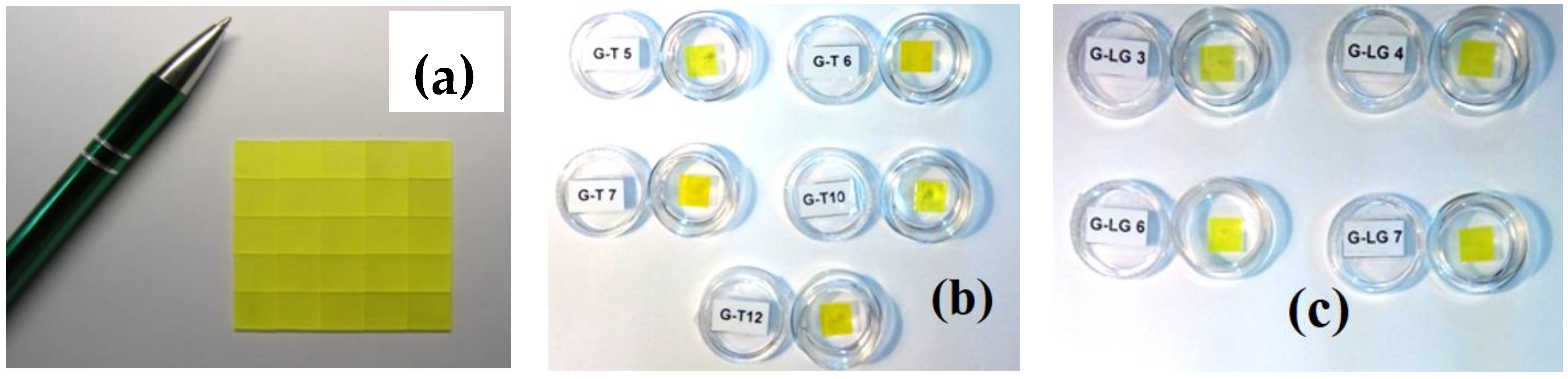
| No SCF and SC | Nominal SCF Content in Melt-Solution | Substrate Type | Real SCF Compositions | h, µm | Tg, °C | fg, μm/min | LY, % Pu239 (12 μs) | LY, % Am241 (3 μs) |
|---|---|---|---|---|---|---|---|---|
| YAG:Ce | Y3Al5O12:Ce | YAG | Y3Al5O12:Ce | 54 | 100 | |||
| GAGG2.5:Ce | Gd3Al2.5Ga2.5O12:Ce | – | – | 900 | 340 | 100 | ||
| GAGG3:Ce | Gd3Al2Ga3O12:Ce | – | – | 900 | 320 | |||
| GAGG2:Ce | Gd3Al3Ga2O12:Ce | GAGG2.5:Ce | Gd3.038Ce0.005Pb0.001 Al3.792Ga1.162O12 | 34 | 970 | 1.13 | 59 | 18.4 |
| GAGG3:Ce | Gd3Al2Ga3O12:Ce | GAGG2.5:Ce | Gd3.08Ce0.003Pb0.077 Al3.141Ga1.67O12 | 51 | 1000 | 1.15 | 42 | 27.1 |
| GAGG3.5:Ce | Gd3Al1.5Ga3.5O12:Ce | GAGG2.5:Ce | Gd3.28Ce0.009Pb0.056 Al2.528Ga2.17O12 | 45 | 974 | 0.56 | 32 | 29.9 |
| GAGG4:Ce | Gd3AlGa4O12:Ce | GAGG2.5:Ce | Gd3.29Ce0.017Pb0.012 Al2.615Ga2.615O12 | 36 | 985 | 1.2 | 31 | 17.9 |
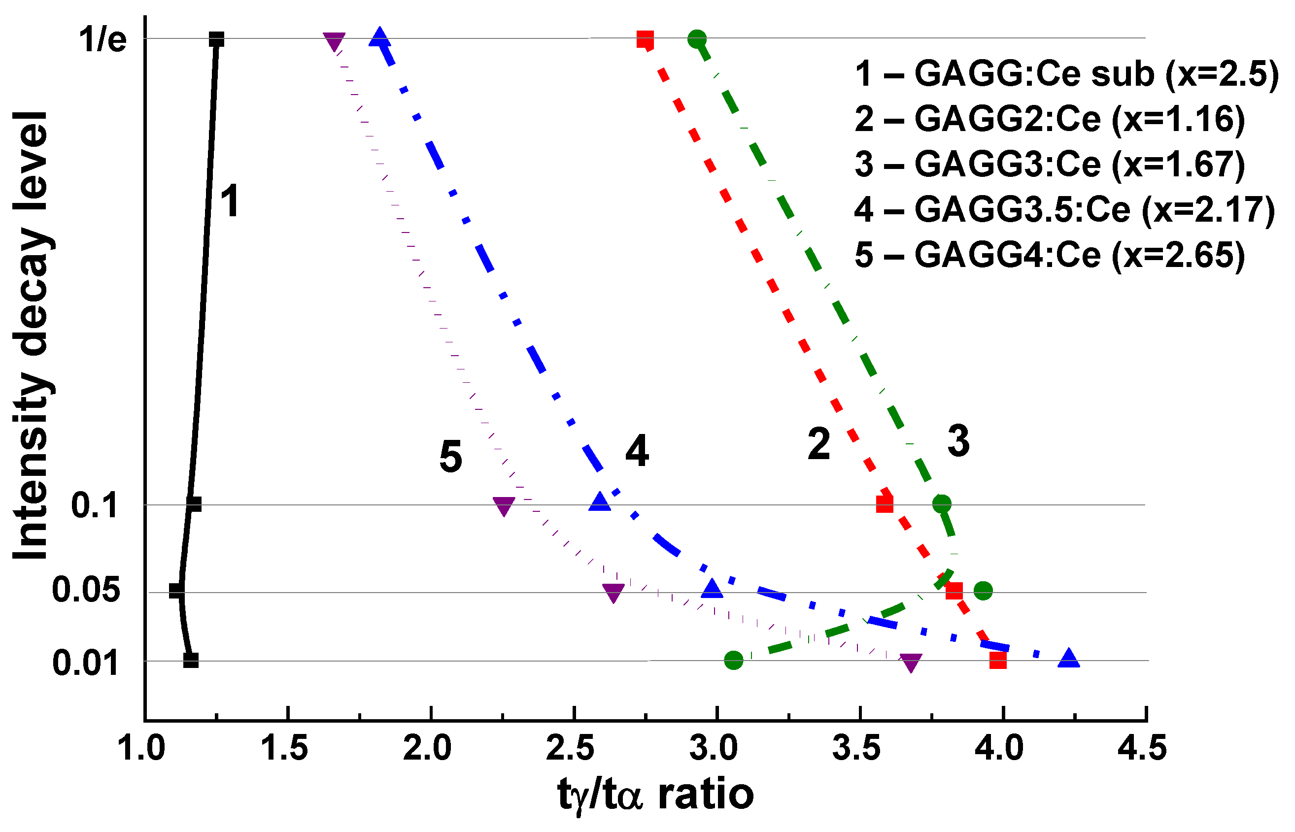
| GAGG2.5:Ce Substrate | GAGG2:Ce SCF/GAGG:Ce Sub | GAGG3:Ce SCF/GAGG:Ce Sub | GAGG3.5:Ce SCF/GAGG:Ce | GAGG4:Ce SCF/GAGG:Ce Sub | ||||||
|---|---|---|---|---|---|---|---|---|---|---|
| tα, ns | tγ, ns | tα, ns | tγ, ns | tα, ns | tγ, ns | tα, ns | tγ, ns | tα, ns | tγ, ns | |
| 1/e | 390 | 310 | 87 | 2239 | 86 | 252 | 129 | 235 | 133 | 208 |
| 0.1 | 925 | 790 | 207 | 742 | 205 | 776 | 270 | 700 | 275 | 583 |
| 0.05 | 1300 | 1170 | 280 | 1072 | 287 | 1128 | 345 | 1029 | 355 | 888 |
| 0.01 | 2875 | 2465 | 638 | 2540 | 835 | 2554 | 533 | 2254 | 590 | 1976 |
| SCF | SC | m,% | λmax, nm | t1/e/t1/20, ns | LY,% |
|---|---|---|---|---|---|
| LuAG:Ce | YAG | −0.82 | 509 | 53 | 205 |
| LuAG:Pr | YAG | −0.8 | 305 | 17 | 79 |
| LuAG:Sc | YAG | −0.8 | 280 | 245; 390 | 96 |
| Lu1.5Gd1.5Al5O12:Ce | YAG | +0.02 | 548 | 50 | 86 |
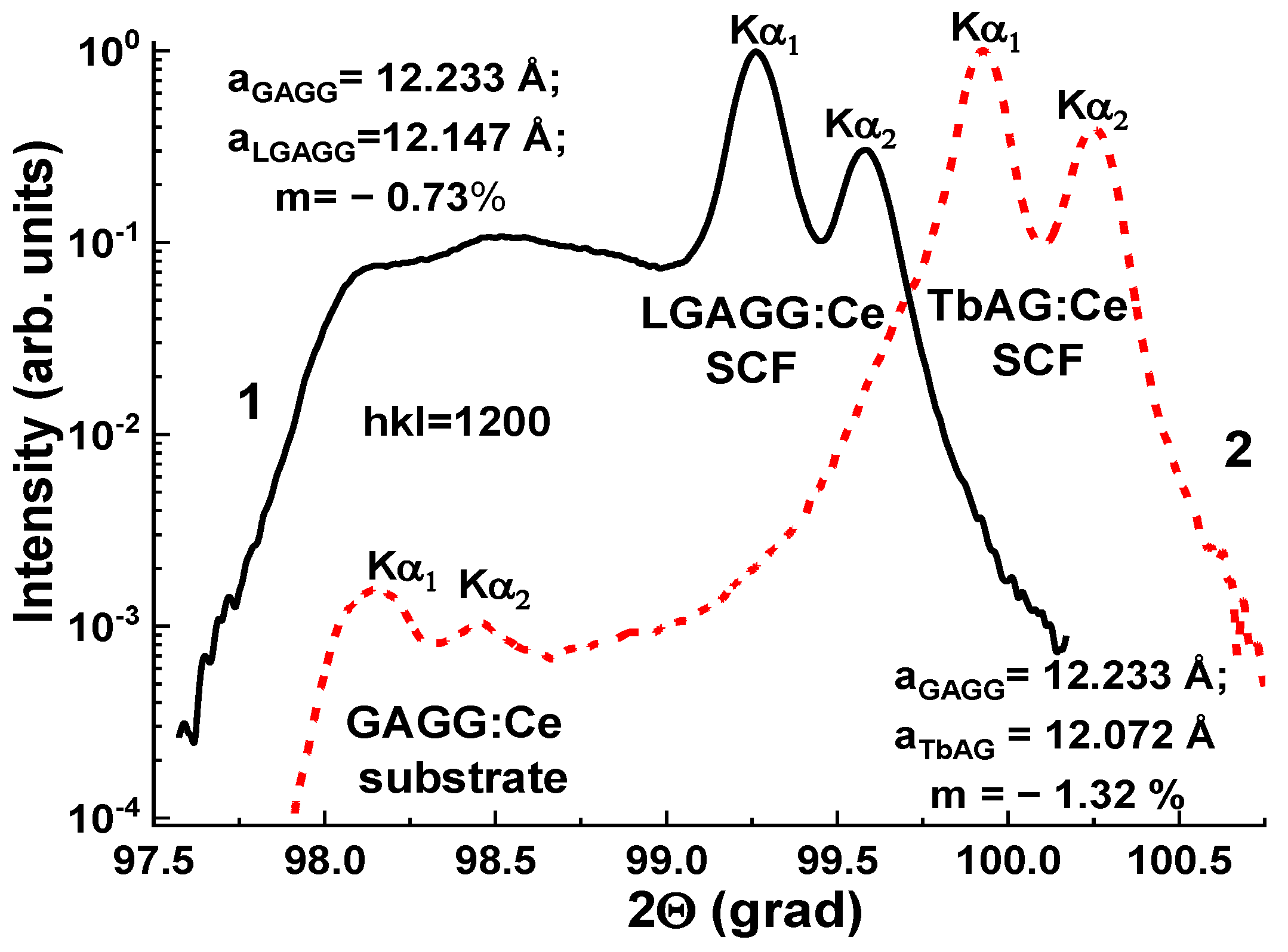
| Lu1.5Gd1.5Al2.75Ga2.25O12:Ce | GAGG | −0.73 | 519 | 51/130 | 145 |
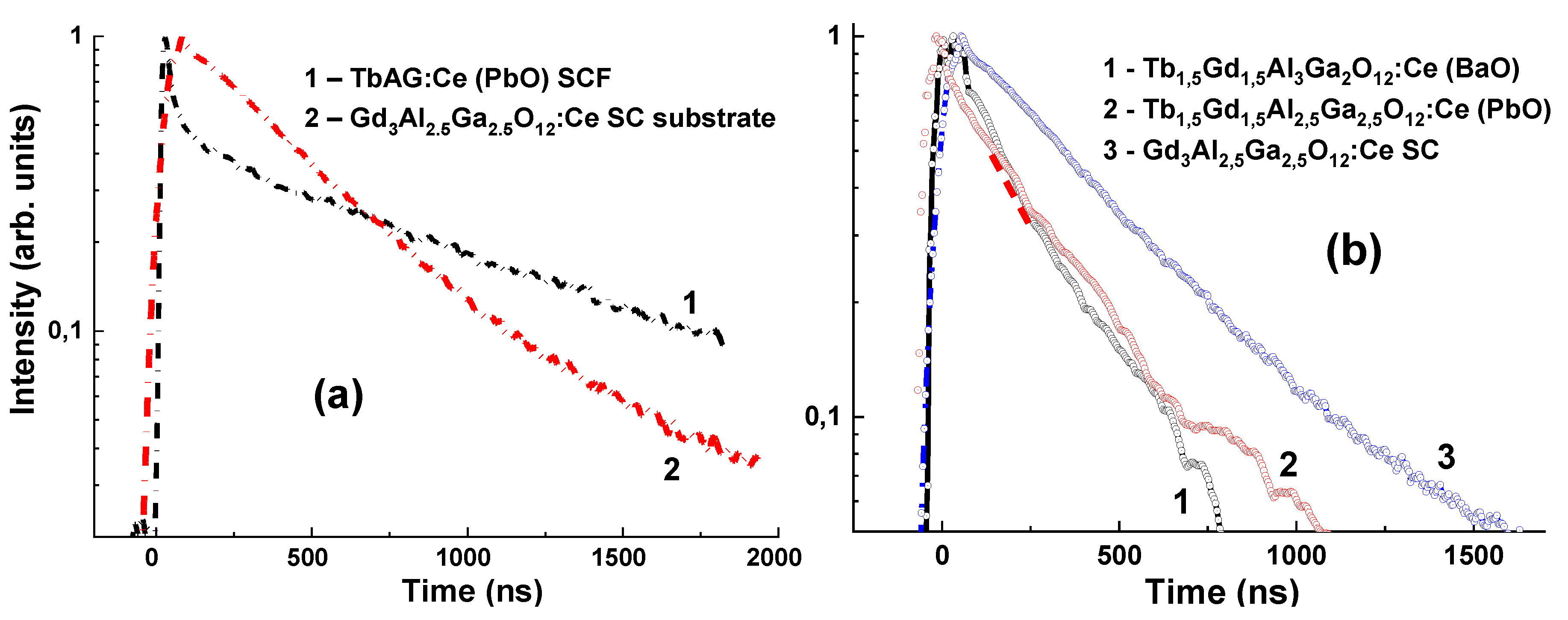
| TbAG:Ce | YAG GAGG | +0.55 −1.29 | 555 560 | 242/1645 306/1795 | 253–264 195 |
| Tb1.5Gd1.5Al2.5Ga2.5O12:Ce (PbO) | GAGG | −0.12 | 543 | 333/990 | 380 |
| Tb1.5Gd1.5Al3Ga2O12:Ce (BaO) | GAGG | −1.30 | 543 | 228/728 | 380 |
| Composite Scintillator | The Best Ratio tα/tγ | Intensity Level for the Best tα/tγ Ratio | Optimal Value of Intensity | Time Interval (ns) |
|---|---|---|---|---|
| LuAG:Pr SCF/LuAG:Ce SC | 3.6 | 0.1 | 0.03–0.4 | 0–700 |
| LuAG:Sc SCF/LuAG:Ce SC | 2.2 | 0.05 | 0.05–0.2 | 200–900 |
| LuAG:Ce SCF/LuAG:Pr SC | 1.1 | 0.05 | 0.05–0.2 | 60–320 |
| Lu2.85Tb0.15AG:Ce SCF/LuAG:Pr SC | 1.2 | 0.05 | 0.1–0.02 | 200–1500 |
| Lu1.75Tb0.3AG:Ce SCF/LuAG:Pr SC | 1 | - | - | - |
| Lu1.35Tb1.65AG:Ce SCF/LuAG:Pr SC | 1.4 | 0.1 | 0.05–0.2 | 250–1000 |
| Lu0.715Tb2.285AG:Ce SCF/LuAG:Pr SC | 4.2 | 0.07 | 0.05–0.36 | 100–3000 |
| LuAG:Ce SCF/LuAG:Sc SC | 2.7 | 0.05 | 0.02–0.2 | 250–110 |
| LuAG:Pr SCF/LuAG:Sc SC | 15.6 | 0.05 | 0.01–0.5 | 0–2500 |
| TbAG:Ce SCF/GAGG:Ce SC | 3 | 0.05 | 0.05–0.2 | 450–3700 |
| LGAGG:Ce SCF/GAGG:Ce SC | 2 | 1/e | 0.2–0.5 | 50–500 |
| GAGG/GAGG | 4.2 | 0.01 | 0.01–0.1 | 600–2700 |
Publisher’s Note: MDPI stays neutral with regard to jurisdictional claims in published maps and institutional affiliations. |
© 2022 by the authors. Licensee MDPI, Basel, Switzerland. This article is an open access article distributed under the terms and conditions of the Creative Commons Attribution (CC BY) license (https://creativecommons.org/licenses/by/4.0/).
Share and Cite
Witkiewicz-Lukaszek, S.; Gorbenko, V.; Zorenko, T.; Syrotych, Y.; Mares, J.A.; Nikl, M.; Sidletskiy, O.; Bilski, P.; Yoshikawa, A.; Zorenko, Y. Composite Detectors Based on Single-Crystalline Films and Single Crystals of Garnet Compounds. Materials 2022, 15, 1249. https://0-doi-org.brum.beds.ac.uk/10.3390/ma15031249
Witkiewicz-Lukaszek S, Gorbenko V, Zorenko T, Syrotych Y, Mares JA, Nikl M, Sidletskiy O, Bilski P, Yoshikawa A, Zorenko Y. Composite Detectors Based on Single-Crystalline Films and Single Crystals of Garnet Compounds. Materials. 2022; 15(3):1249. https://0-doi-org.brum.beds.ac.uk/10.3390/ma15031249
Chicago/Turabian StyleWitkiewicz-Lukaszek, Sandra, Vitalii Gorbenko, Tetiana Zorenko, Yurii Syrotych, Jiri A. Mares, Martin Nikl, Oleg Sidletskiy, Pawel Bilski, Akira Yoshikawa, and Yuriy Zorenko. 2022. "Composite Detectors Based on Single-Crystalline Films and Single Crystals of Garnet Compounds" Materials 15, no. 3: 1249. https://0-doi-org.brum.beds.ac.uk/10.3390/ma15031249