Numerical Algorithm for Dynamic Impedance of Bridge Pile-Group Foundation and Its Validation


1
School of Civil and Transportation Engineering, Beijing University of Civil Engineering and Architecture, Beijing 100044, China
2
Department of Civil Engineering, Tsinghua University, Beijing 100084, China
3
School of Civil Engineering, Beijing Jiaotong University, Beijing 100044, China
*
Author to whom correspondence should be addressed.
Algorithms 2021, 14(8), 247; https://0-doi-org.brum.beds.ac.uk/10.3390/a14080247
Submission received: 19 July 2021
/
Revised: 16 August 2021
/
Accepted: 19 August 2021
/
Published: 20 August 2021
Abstract
:The characteristics of bridge pile-group foundation have a significant influence on the dynamic performance of the superstructure. Most of the existing analysis methods for the pile-group foundation impedance take the trait of strong specialty, which cannot be generalized in practical projects. Therefore, a project-oriented numerical solution algorithm is proposed to compute the dynamic impedance of bridge pile-group foundation. Based on the theory of viscous-spring artificial boundary, the derivation and solution of the impedance function are transferred to numerical modeling and harmonic analysis, which can be carried out through the finite element method. By taking a typical pile-group foundation as a case study, the results based on the algorithm are compared with those from existing literature. Moreover, an impact experiment of a real pile-group foundation was implemented, the results of which are also compared with those resulting from the proposed numerical algorithm. Both comparisons show that the proposed numerical algorithm satisfies engineering precision, thus showing good effectiveness in application.
1. Introduction
Pile-group foundation has been widely used in bridge engineering, and pile–soil interaction has a significant effect on the dynamic performance of the superstructure [1,2,3,4]. Mylonakis et al. [5] investigated the influence of soil–structure interaction (SSI) on the seismic response of structures by using recorded motions, and concluded that some simplifications about SSI in design may lead to detrimental consequences. Soyluk et al. [6] studied the effects of SSI and spatially varied ground motions on the seismic response of a cable-stayed bridge, and the results indicated that softer soils amplify the displacement response of the bridge. Shirgir et al. [7] developed an analytical model to obtain free vibration frequencies of bridges with soil–structure interaction taken into consideration, and found that the effect of SSI is significant for soils with a shear wave velocity less than 175 m/s. Gara et al. [8] discussed the contribution of SSI to the bridge dynamics, and found that SSI may significantly affect the structural dynamics, especially in the case of soft or medium soil deposits. Qiao et al. [9] established an analytical model of the train–bridge system considering SSI based on the substructure method, and found that it is important to consider SSI in the dynamic analysis of train–bridge systems, but such influence becomes weaker with the increase in the soil shear wave velocity. Tochaei et al. [10] investigated the effects of soil–structure interaction and near-field seismic ground motions on cable-stayed bridges based on experiments and numerical analysis; their results indicated that the effect of foundation soil stiffness on the response of the bridge was influenced by the type of input ground motion and that the bridge response was amplified when their foundation was in softer soils. All of the above studies indicate the importance of considering SSI in the dynamic analysis of bridges.
There are two main approaches for soil–structure analysis during the dynamic analysis of bridges—namely, the direct approach, and the substructure approach [11]. Compared with the direct approach—which studies the structure, foundation, and soil simultaneously (usually by means of a finite element model)—the substructure approach, which divides the whole system into two subsystems (superstructure subsystem and soil–foundation subsystem), is less time consuming and more efficient, for the two subsystems can be treated separately with their respective optimal method. Based on the substructure method, the coupling of two interacting subsystems is realized through the concept of the soil–foundation dynamic impedance functions. Foundation impedance functions represent the dynamic stiffness of the soil medium surrounding the foundation, which characterize the compliant base restraints for the superstructure and the input motion experienced by the foundation, thus providing a simple means of accounting for pile–soil interaction [12]. Therefore, the study of the solution of dynamic impedance functions of pile-group foundation has drawn more and more attention.
The generally accepted standard solutions for the dynamic response of pile groups in viscoelastic media were obtained by Kaynia and Kausell, by means of the boundary integral method [13]. Afterwards, Gazetas et al. [14] proposed a method to calculate the impedance functions of pile-group foundations using a simplified beam-on-dynamic-Winkler-foundation model and Green’s function-based rigorous method. Based on the thin layer method and the flexible volume method, Jiang et al. [15] calculated the impedance functions of pile-group foundations from literature as well as in a practical layered site, and compared the results with those in the literature [16] and from experimental data. In recent years, more and more methods have been proposed for the impedance functions of pile-group foundations under various conditions [17,18,19,20,21,22,23]. For example, Padrón et al. [24] presented a BEM–FEM model for the time-harmonic dynamic analysis of piles and pile groups embedded in an elastic half-space, and successfully reduced the number of degrees of freedom. Emani and Maheshwari [25] developed a general three-dimensional finite element procedure for the dynamic impedances of pile groups with caps embedded in isotropic homogeneous elastic soils. Ai et al. [26] investigated the dynamic behavior of a laterally loaded fixed-head pile group in a transversely isotropic multilayered half-space by BEM–FEM coupling method. With the porous medium model and the Rayleigh–Love rod model describing the soil and the pile groups, respectively, Zhang et al. [27] developed a simplified analytical solution for the vertical impedance function of viscoelastic pile groups partially embedded in a layered, transversely isotropic, liquid-saturated, viscoelastic soil medium. Dezi et al. [28,29] proposed a numerical model for the 3D kinematic interaction analysis of vertical and inclined pile groups in horizontally layered soils, based on BEM–FEM coupling, in which piles are modelled with finite beam elements while the soil is schematized with infinite independent horizontal layers. Moghaddasi et al. [30] presented a hybrid analytical–numerical method for the dynamic analysis of piles and pile groups embedded in nonhomogeneous transversely isotropic media subjected to lateral excitations, in which the piles are simulated using finite elements and the interactions between piles and soil are captured through a system of rigid, massless elements. Varghese et al. [31] proposed a substructure-method-based soil–structure interaction analysis model to study the vertical and horizontal dynamic impedances of piled rafts in homogeneous and layered soil conditions. Wang and Ai [32] developed a method to compute the dynamic response of pile groups in layered soils with compressible constituents by combining the analytical layer element method and finite element method. Zhang et al. [33] presented an analytical method to study the horizontal dynamic response of pile groups embedded in partially saturated soil based on the motion theory of three-phase poroelastic media, with the pile–soil system modeled using the Timoshenko beam theory and soil resistance incorporated using Novak’s plane strain model. Almost all of the abovementioned methods possess the trait of strong specialty, the theoretical derivation procedures of which are complex and even involve programming processes. In view of the complexity of actual soil layers and the parametric diversity of bridge group foundations, it can be found that the above calculation methods are too complex and specialized to be generalized in practical projects.
Therefore, this paper presents a project-oriented numerical algorithm for the dynamic impedance of bridge pile-group foundation. Based on the viscous-spring artificial boundary theory, the derivation and solution of the impedance function are transferred to numerical modeling and harmonic analysis, which can be carried out using the finite element method. The applicability of the proposed numerical algorithm is verified by comparing its calculation results with those obtained through methods in existing literature and a field experiment. Both comparisons show that the numerical algorithm satisfies the project demand of analysis precision, thus showing good effectiveness in application.
2. Project-Oriented Numerical Algorithm for Impedance of Pile-Group Foundation
2.1. Definition of the Impedance Functions
For a generic bridge founded on pile groups, the soil–structure interaction problem can be conveniently studied in the frequency domain by assuming a linear behavior for soil and structure. By adopting a finite element method, the following system of complex linear equations governs the dynamics of the whole system [3]:
where Z is the dynamic stiffness matrix of the soil–foundation–superstructure system; d is the vector of the nodal displacements; and f is the vector of nodal forces.
With the assumption that the caps connecting the pile heads are rigid, and assigning different master nodes to them, Equation (1) can be partitioned as:
in which the subscripts s, f, and e denote the superstructure, the rigid pile cap, and the piles, respectively. It is worth noting that no displacement component for the soil appears in Equation (2) because the pile–soil interaction is accounted for in the definition of the dynamic stiffness matrices relevant to the rigid caps and piles [3].
With the linear assumption, and according to the substructure approach, the inertial interaction for the superstructure is governed by:
and for the soil–foundation system, the kinematic interaction problem is governed by:
where de,kin are the displacements of the embedded piles and dFIM are those of the master modes of the rigid caps due to the kinematic interaction. Then, the impedance matrix of the soil–structure system S can be expressed as:
It can be found that foundation impedance functions can be defined as the ratio of a harmonic force (or a moment) applied on the foundation–soil interface to the corresponding harmonic displacement (or rotation), dependent not only on the frequency of the excitation, but also on the foundation geometry and the dynamic characteristics of the soil medium [12]. Based on this definition, a project-oriented numerical algorithm for impedance functions of bridge pile-group foundation is proposed. First, according to the actual situation of the bridge site, a refined finite element analysis model of the cap, pile group, and surrounding soil is established; second, based on the viscous-spring artificial boundary theory, a series of springs and dampers are set at the boundaries of the aforementioned model so as to simulate the influence of the infinite soil; third, a unit resonant force in each direction within the concerned frequency band is applied at the center of the cap, and the corresponding displacement response can then be obtained—namely, the dynamic flexibility matrix; finally, the impedance functions of the pile-group foundation can be obtained in virtue of the inverse properties of the dynamic flexibility matrix and dynamic stiffness matrix.
2.2. Refined FE Model of the Cap–Pile Group–Surrounding Soil System
The pile-group foundation of the bridge can be regarded as a dynamic interaction system composed of the pile cap, pile group, and layered soil, the pile group effect of which is prominent. Therefore, to better consider the influence of the pile cap, pile layout, pile spacing, layered soil, soil properties, and other factors on the dynamic performance of pile-group foundations, a three-dimensional analysis model is necessary.
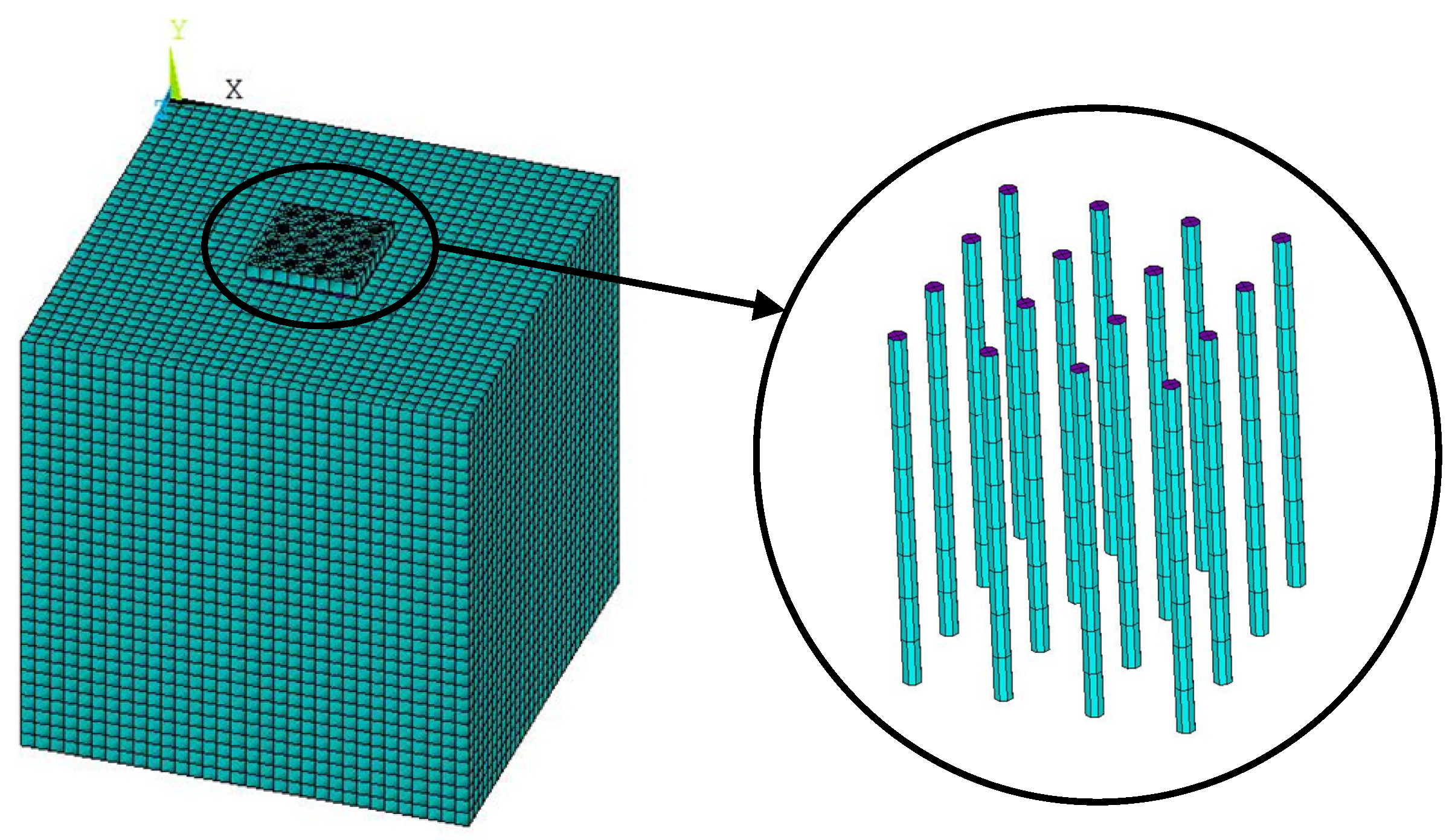
Based on the finite element method, which is widely recognized and mastered by structural engineers, a refined FE model of the cap–pile group–surrounding soil system is established, as shown in Figure 1. Here, the ANSYS software [34] is used for establishing the model, in which the cap, piles, and soil medium are all modelled with Solid45 elements. The connection between the cap and the piles, and that between the piles and the soil, are realized by master–slave nodes or constraint equations. It is assumed that the interface between the piles and the surrounding soil is always in an ideal bonding state.
2.3. Boundary Conditions
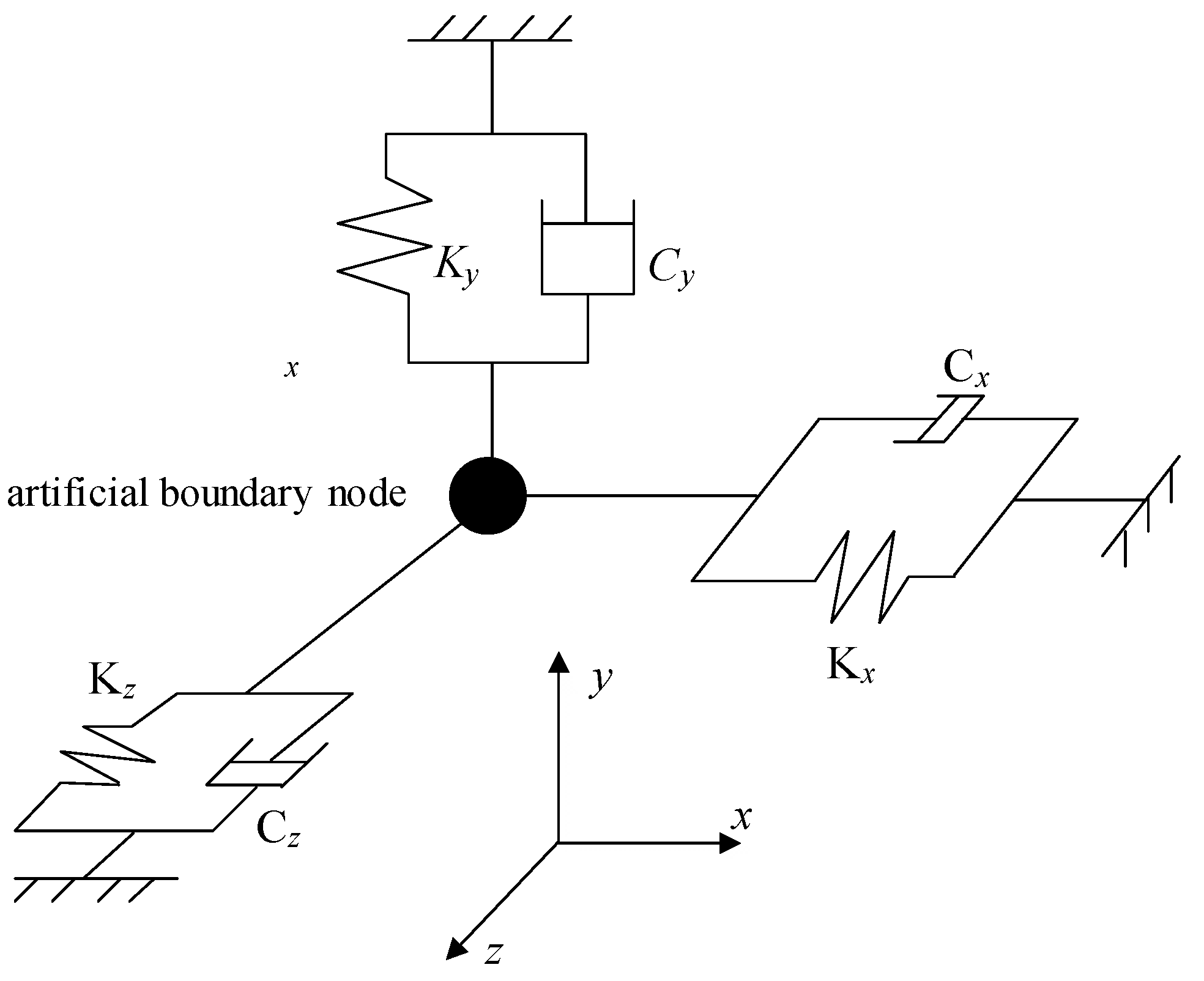
To establish the FE model of the cap–pile group–surrounding soil system, it is necessary to extract a finite domain from the unbounded soil medium. In order to accurately model the originally continuous medium after extraction, the propagation characteristics of the soil should be kept unchanged, which necessitates an artificial boundary capable of absorbing the energy of the scattering waves [35]. For this purpose, the modified viscous-spring artificial boundary proposed by Du et al. [36,37,38] was adopted, since it not only satisfies the above criterion, but also has the advantages of high accuracy, adequate stability, and convenient application. The three-dimensional sketch of the adopted artificial boundary is shown in Figure 2.
The parameters of the springs and dampers that constitute the artificial boundary can be obtained by the following equations:
where G, ρ, and λ are the shear modulus, mass density, and Lamé constant of the soil, respectively; cp and cs are the velocity of P-wave and S-wave, respectively; r is the distance between the point load and the boundary; and α and β are coefficients, the recommended empirical values of which are 0.8 and 1.1, respectively.
To simulate the springs and dampers of the artificial boundary, the combin14 element with one end fixed is used in the ANSYS model; then, the FE model used for calculating the impedance functions of pile-group foundations is completed.
2.4. Calculation of the Impedance Funcitons
The motion equation of the cap–pile group–soil system under harmonic load can be expressed as:
where m, c, and k are the mass matrix, damping matrix, and stiffness matrix, respectively; u is the displacement vector; and p is the force vector whose frequency is ω.
Assuming that:
by substituting Equation (9) into Equation (8), it can be obtained that:
where:
Then, can be obtained through the decomposition of complex matrix kc.
By applying the unit harmonic loads with different frequencies at the center of the cap top in the vertical, transverse, longitudinal, transverse rotation, and longitudinal rotation directions, the dynamic flexibility matrix of the pile foundation can be obtained by calculating the corresponding displacement, which can be expressed as:
where the subscripts Z, Y, X, RX, and RY represent the vertical, transverse, longitudinal, longitudinal rotation, and transverse rotation directions, respectively. Finally, the impedance functions of the pile-group foundation can be obtained in virtue of the inverse properties of the dynamic flexibility matrix and dynamic stiffness matrix, as follows:
3. Verification of the Numerical Algorithm
In this section, the calculation results of the proposed algorithm are compared with those obtained via existing methods and field test results, in order to verify its applicability.
3.1. Comparison with Existing Methods
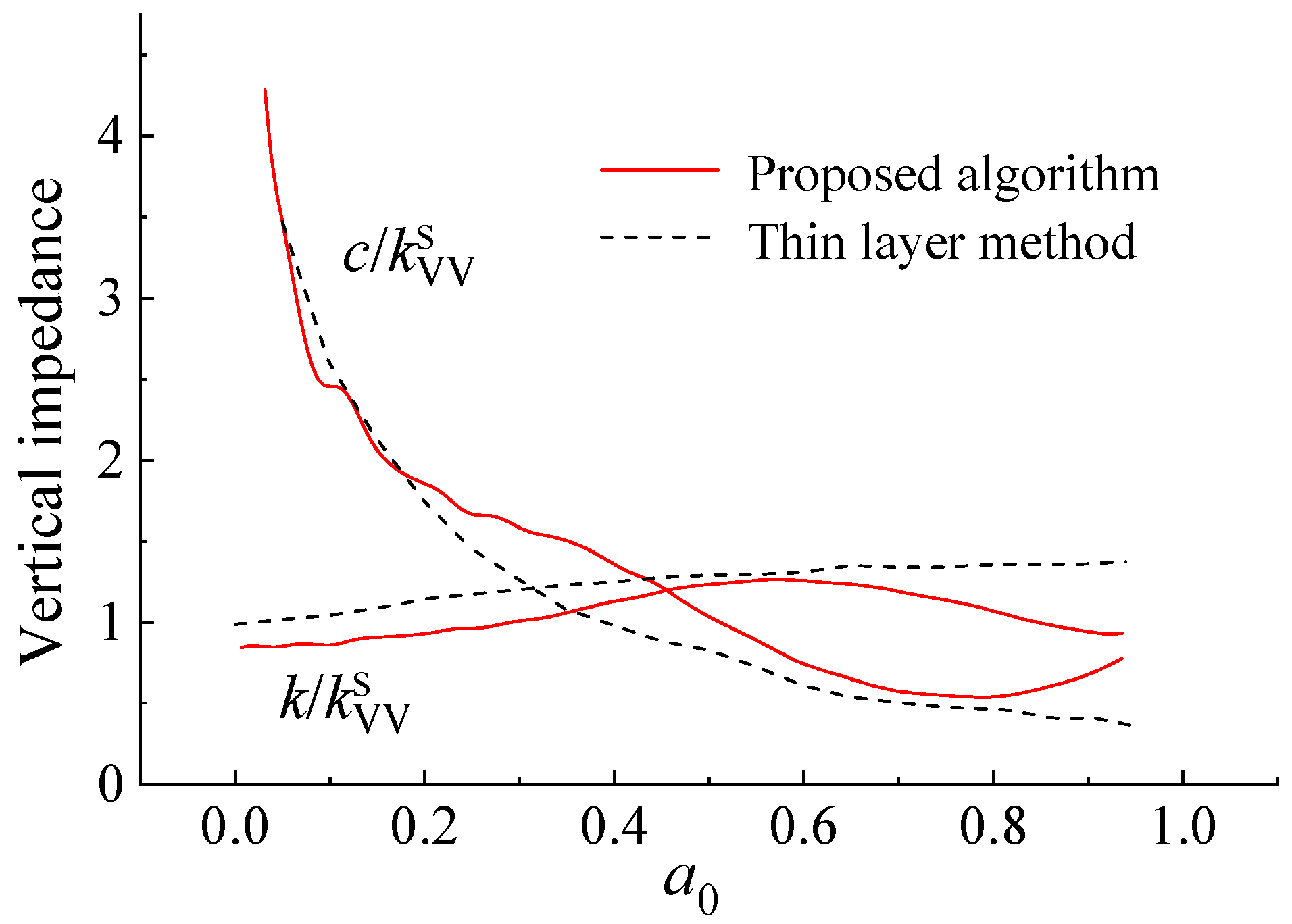
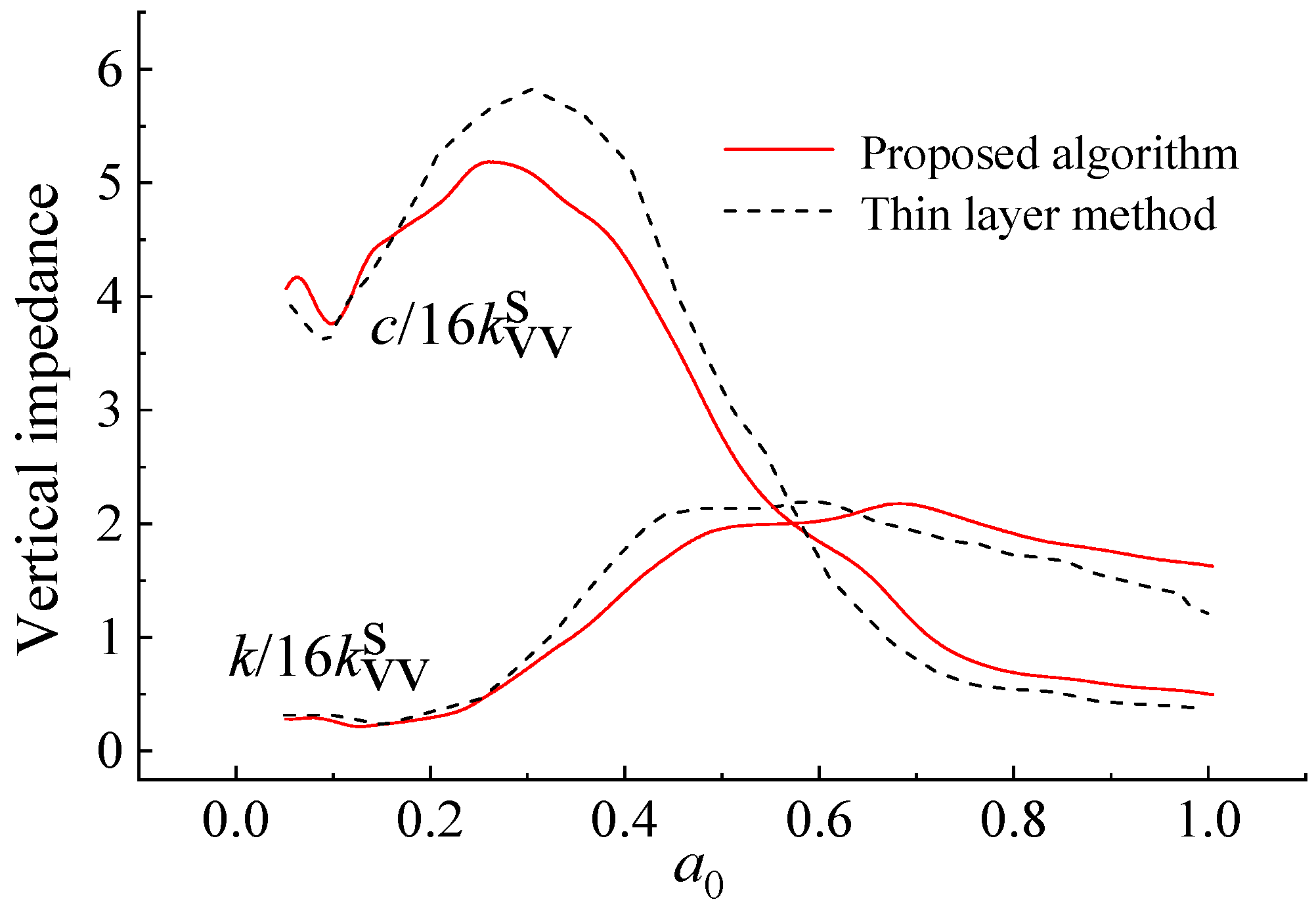
First, a 4 × 4 pile-group foundation was chosen as an example, the parameter values of which are taken from [15] and shown in Table 1. For comparison, both the thin layer method presented in [15] and the proposed algorithm were used to obtain the impedance functions of the single pile as well as the pile-group foundation.
The overall size of the FE model in the proposed algorithm is 80 m × 80 m × 80 m, and the size of the soil element is set as 2.5 m. The damping of the piles is neglected in accordance with the benchmark.
Figure 3 and Figure 4 show the calculated vertical impedance functions of the single pile and the pile-group foundation, respectively, as obtained by the proposed algorithm and the thin layer method.
The impedance functions are expressed as k + ia0c, where k and c are the stiffness item and the damping item, respectively. represents the vertical static stiffness of a single pile in elastic half-space, while a0 is the dimensionless frequency, which can be expressed as:
where ω is the frequency; and d and Vs are the pile diameter and shear wave velocity of the soil, respectively.
It can be seen that the results obtained by the proposed algorithm are consistent with those obtained by the thin layer method. Even though there is some error, which probably occurs due to the relatively large element size or the difference between calculation assumptions, from the perspective of practical application, the results are sufficiently accurate to meet the requirements of engineering.
Second, the results obtained by the proposed algorithm were compared with those obtained through a rigorous method presented in a recent study [39] based on a 4 × 4 pile-group foundation. For the results presented in this work, it was assumed that υs (Poisson’s ratio of the soil) = 0.4, Epile/Esoil = 100 (Epile and Esoil are the elasticity moduli of the piles and soil, respectively), υp (Poisson’s ratio of the piles) = 0.25, L (length of the piles) = 15d (where d is the pile diameter), S (pile spacing) = 5d, and ρs/ρp = 0.7, where ρs and ρp are the mass density of the soil and the piles, respectively.
Figure 5 shows the calculated vertical impedance functions of the pile-group foundation, as obtained by the proposed algorithm and the existing rigorous method. It should be noted that the symbols in Figure 5 have the same meanings as those in Figure 4. It can be seen that the results obtained by the proposed algorithm are also consistent with those obtained by the rigorous method. The error of the maximum stiffness item is 0.6% and 4% as calculated from Figure 4 and Figure 5, respectively, falling within an acceptable range of values for engineering projects. Therefore, through classic and recent numerical examples, the effectiveness of the proposed algorithm is verified and, compared with other methods that require a higher theoretical basis of users, the proposed algorithm is more friendly and easy to use for most engineers, which has certain advantages.
3.2. Field Experiment
3.2.1. Description of the Experiment
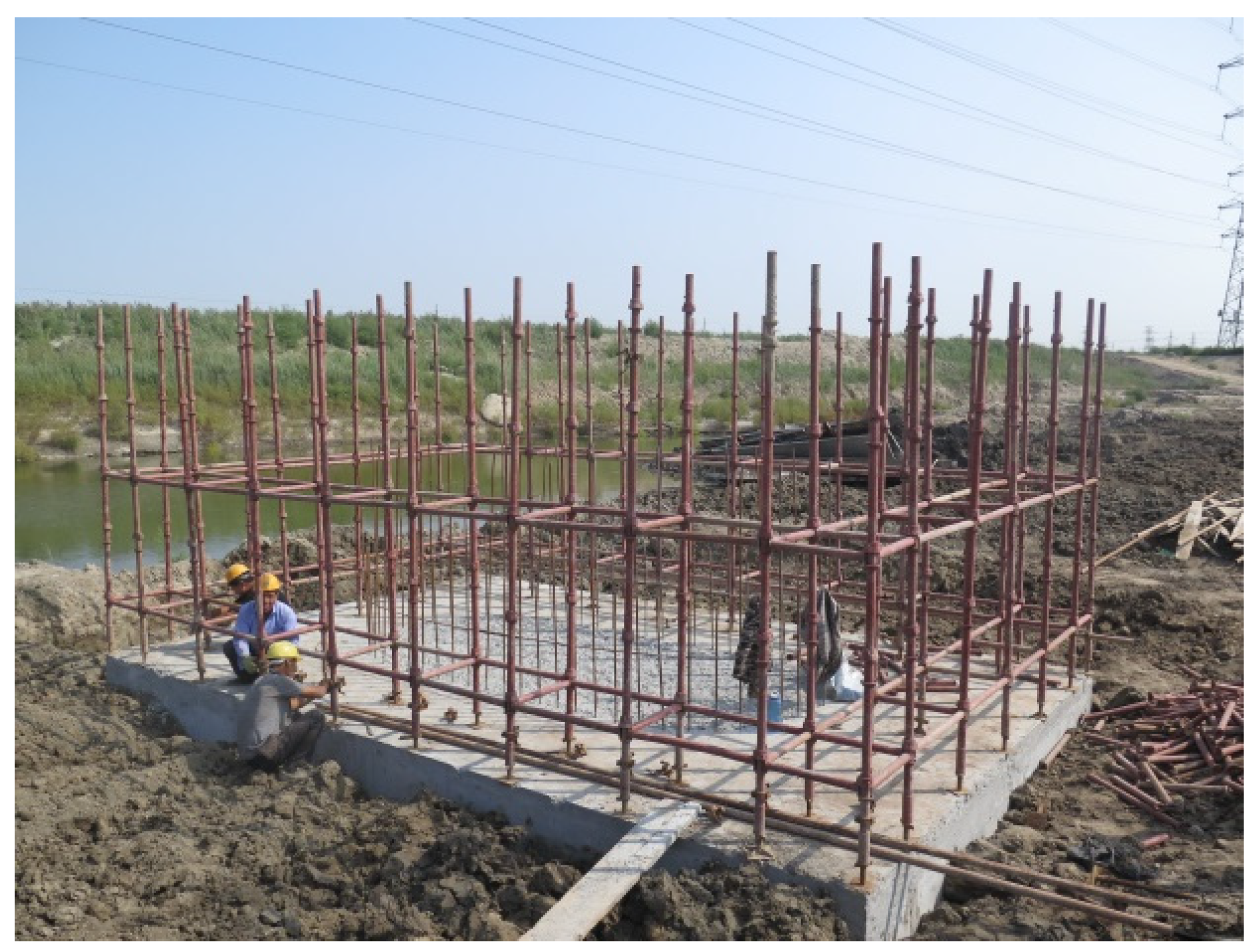
To verify the proposed numerical algorithm, a field experiment on a real bridge in Tianjin was carried out. Figure 6 shows the testing site. It can be seen that the construction of the pile-group foundation has been completed, while the superstructure has not yet been constructed.
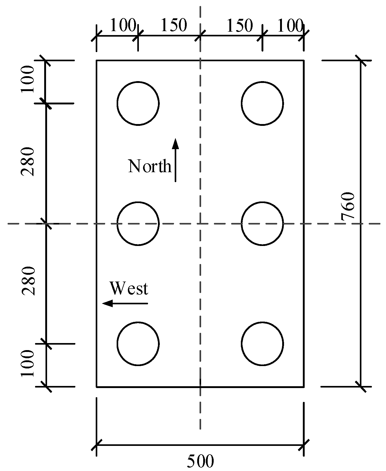
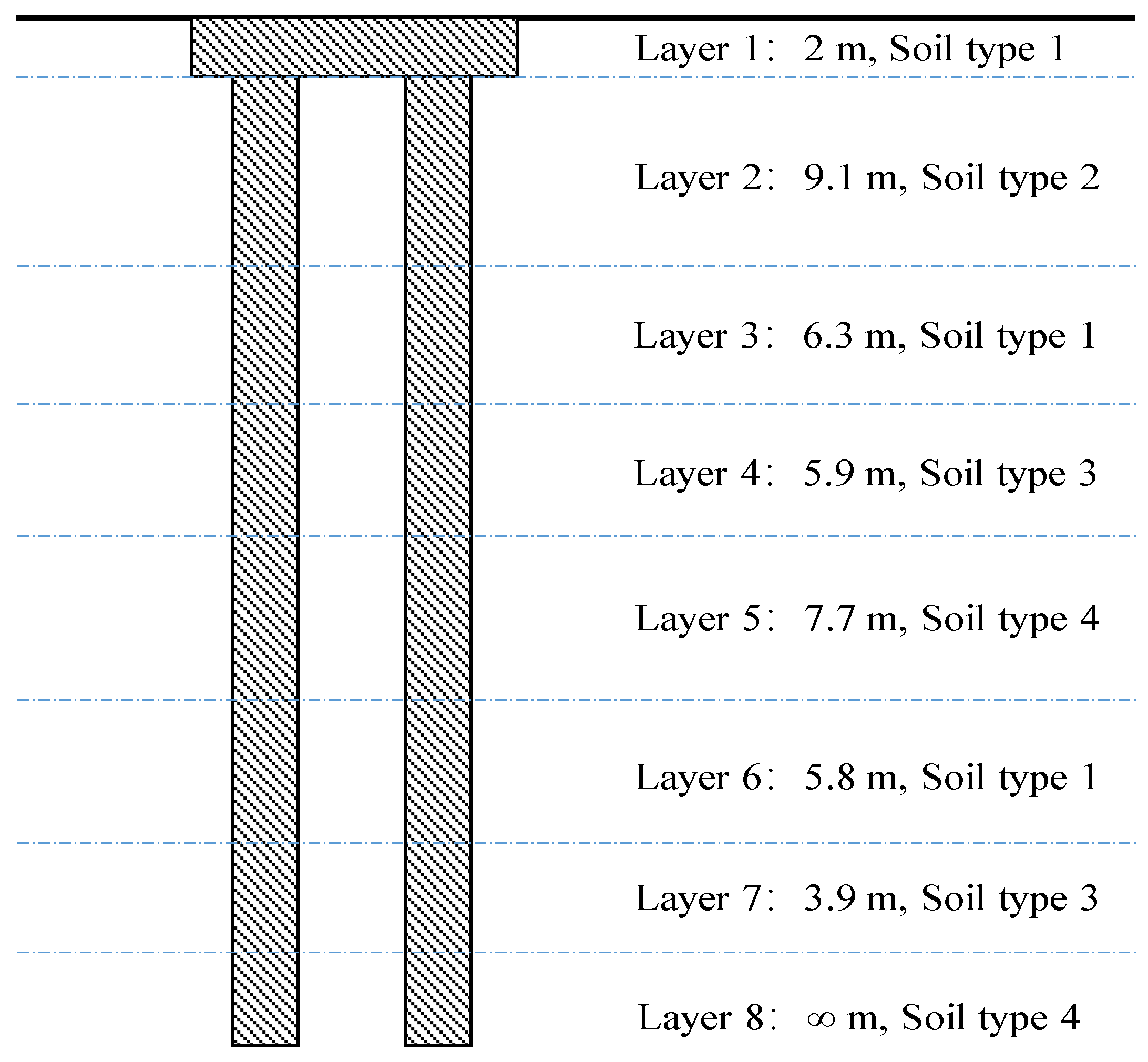
The size of the testing cap was 7.6 m × 5 m × 2 m, and each foundation had 6 piles in total, the layout of which is shown in Figure 7. The length and diameter of each pile were 42.1 m and 1.0 m, respectively. The main kinds of soil in the bridge site were silt, mucky silty clay, silty clay, and clay. The distribution of the soil is shown in Figure 8, and the corresponding characteristics are shown in Table 2.
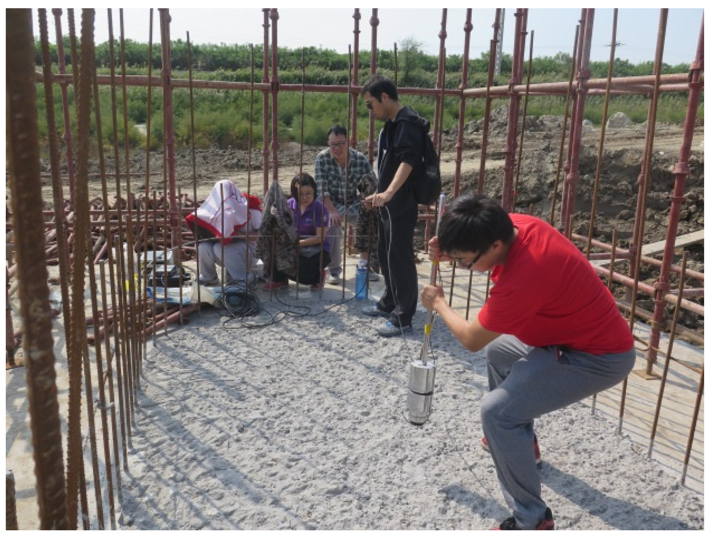
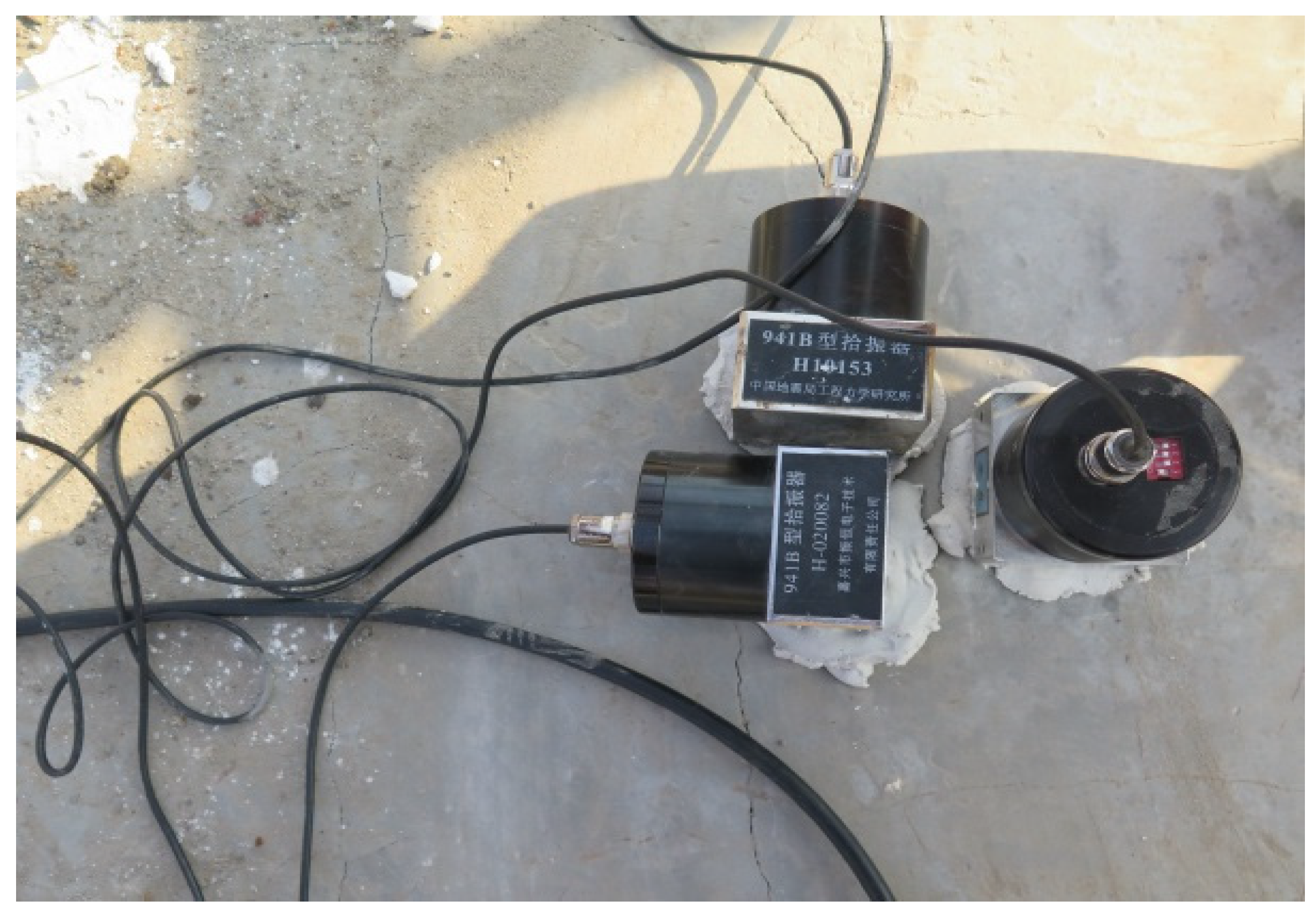
During the test, a high-elastic cohesive hammer was used to impact the designated position of the pile cap for excitation (as shown in Figure 9), and the responses of the foundation could be acquired by installing a series of vibration sensors (Figure 10) on the top of the cap.
There were three working conditions in the test:
- (1)
- Impact the top of the cap in a vertical direction and obtain its vertical acceleration response;
- (2)
- Impact the north side of the cap and obtain its acceleration response in a north–south direction;
- (3)
- Impact the east side of the cap and obtain its acceleration response in an east–west direction.
The type of hammer and the data acquisition instrument were DFC-1 and INV3018A, respectively—both from the China Orient Institute of Noise & Vibration. The type of sensor selected was 941B, from the Institute of Engineering Mechanics, whose sensitivity and passband are 0.3 Vs2/m and 0.25–80 Hz, respectively, due to microtremors, and their sensitivity can meet the required test precision. The sampling frequency was set to 256 Hz and, under each working condition, the hammer was knocked about 20 times so that the signal could be collected.
3.2.2. Experimental Results
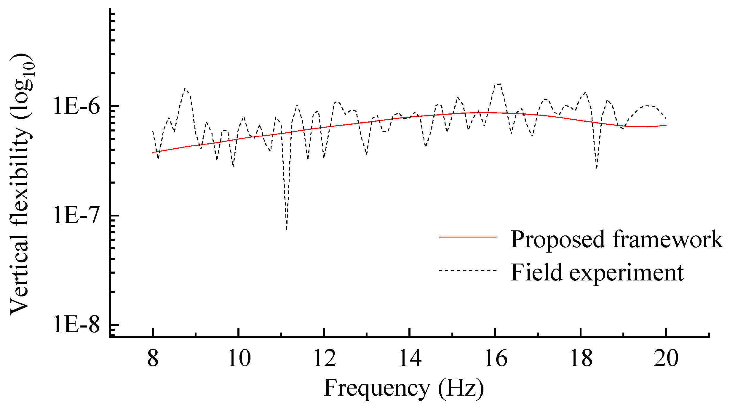
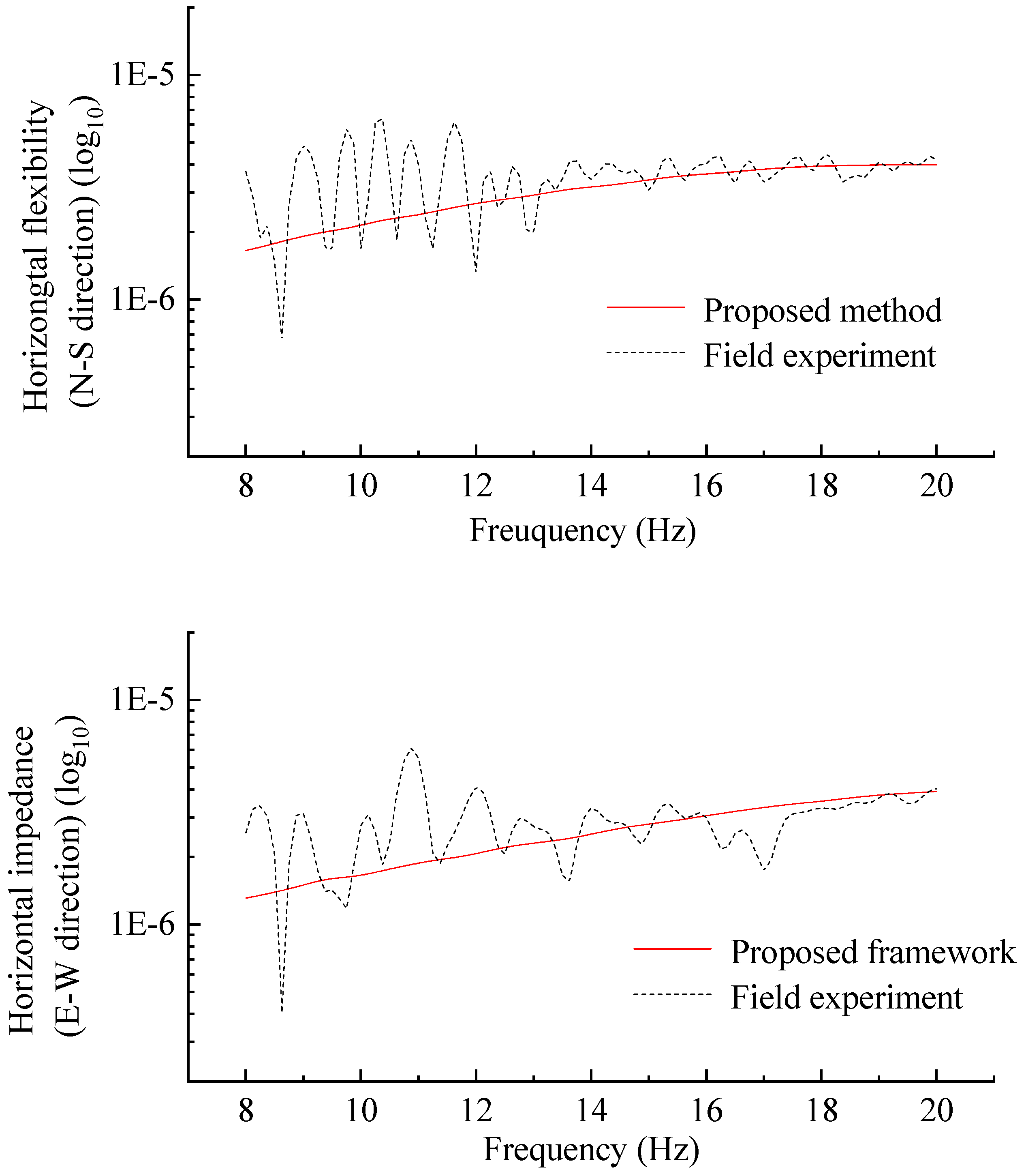
The impedance functions of the pile-group foundation can be obtained in virtue of the inverse properties of the dynamic flexibility matrix and dynamic stiffness matrix. In other words, by comparing the dynamic flexibility of the pile-group foundation measured experimentally with that calculated by the proposed algorithm, the applicability of the latter in calculating the impedance functions of pile-group foundations can be verified.
Figure 11 shows the vertical and horizontal (in both north–south direction and east–west directions) dynamic flexibility of the pile-group foundation obtained by the proposed algorithm and field experiment. There exists interference from passing trains and large-scale mechanical operation around the test site, the low-frequency component of which is large. Meanwhile, in consideration of the limitations of the test equipment, the data within the range of 8–20 Hz are analyzed and compared.
It can be seen that the dynamic flexibility of the pile-group foundation in three directions obtained from the proposed algorithm is in good agreement with the results from the field experiment in the frequency range of 8–20 Hz, which once again confirms the applicability of the proposed algorithm for solving the dynamic impedance of pile-group foundations.
4. Conclusions
Existing research methods for the dynamic impedance functions of bridge pile-group foundations are too complex and specialized to be generalized in practical projects. Therefore, based on the viscous-spring artificial boundary theory and the finite element method, a project-oriented numerical algorithm for the impedance of bridge pile-group foundations is proposed in this paper, through which the dynamic impedance function is calculated and obtained according to its definition.
The calculation results are compared with those obtained by the methods presented in existing literature, as well as those from a field experiment. The comparisons show that the results obtained by the numerical algorithm are consistent with those obtained by existing methods (error of maximum stiffness item is less than 5%) and the field experiment, and its accuracy can meet the needs of engineering, showing the effectiveness of the proposed numerical algorithm.
The study in this paper may be beneficial for simplifying the modeling of the complex train–bridge–foundation–soil coupled system, and provide an efficient and simple means of further studying the influence of pile–soil interaction on the seismic response of a coupled train–bridge system.
Author Contributions
Methodology, H.Q. and X.D.; software, C.W.; validation, C.W., H.Q. and Y.W.; writing—original draft preparation, C.W.; writing—review and editing, H.Q. and Y.W. All authors have read and agreed to the published version of the manuscript.
Funding
This research was funded by the Fundamental Research Fund for Beijing University of Civil Engineering and Architecture (Grant No. X20033), the Beijing Municipal Natural Science Foundation (grant No. 8204058), and the Program for Scientific Research of Beijing Education Commission (grant No. KM202110016013).
Institutional Review Board Statement
Not applicable.
Informed Consent Statement
Not applicable.
Data Availability Statement
Not applicable.
Conflicts of Interest
The authors declare no conflict of interest.
References
- Zhang, L.X.; Gu, Y. Seismic analysis of a curved bridge considering soil-structure interactions based on a separated foundation model. Appl. Sci. 2020, 10, 4260. [Google Scholar] [CrossRef]
- Zhao, Q.H.; Dong, S.; Wang, Q.W. Seismic response of skewed integral abutment bridges under near fault ground motions, including soil-structure interaction. Appl. Sci. 2021, 11, 3217. [Google Scholar] [CrossRef]
- Carbonari, S.; Dezi, F.; Leoni, G. Seismic soil-structure interaction in multi-span bridges: Application to a railway bridge. Earthq. Eng. Struct. Dyn. 2011, 40, 1219–1239. [Google Scholar] [CrossRef]
- González, F.; Padrón, L.A.; Carbonari, S.; Morici, M.; Aznárez, J.J.; Dezi, F.; Leoni, G. Seismic response of bridge piers on pile groups for different soil damping models and lumped parameter representations of the foundation. Earthq. Eng. Struct. Dyn. 2019, 48, 1–22. [Google Scholar] [CrossRef]
- Mylonakis, G.; Gazetas, G. Seismic soil-structure interaction: Beneficial or detrimental? J. Earthq. Eng. 2000, 4, 277–301. [Google Scholar] [CrossRef]
- Soyluk, K.; Sicacik, E.A. Soil-structure interaction analysis of cable-stayed bridges for spatially varying ground motion components. Soil Dyn. Earthq. Eng. 2012, 35, 80–90. [Google Scholar] [CrossRef]
- Shirgir, V.; Ghanbari, A.; Shahrouzi, M. Natural frequency of single pier bridges considering soil-structure interaction. J. Earthq. Eng. 2016, 20, 611–632. [Google Scholar] [CrossRef]
- Gara, F.; Regni, M.; Roia, D.; Carbonari, S.; Dezi, F. Evidence of coupled soil-structure interaction and site response in continuous viaducts from ambient vibration tests. Soil Dyn. Earthq. Eng. 2019, 120, 408–422. [Google Scholar] [CrossRef]
- Qiao, H.; Xia, H.; Du, X.T. Dynamic Analysis of an Integrated Train-bridge-foundation-soil System by the Substructure Method. Int. J. Struct. Stab. Dyn. 2018, 18, 1850069. [Google Scholar] [CrossRef]
- Tochaei, E.N.; Taylor, T.; Ansari, F. Effects of near-field ground motions and soil-structure interaction on dynamic response of a cable-stayed bridge. Soil Dyn. Earthq. Eng. 2020, 133, 106115. [Google Scholar] [CrossRef]
- Carbonari, S.; Morici, M.; Dezi, F.; Leoni, G. A lumped parameter model for time-domain inertial soil-structure interaction analysis of structures on pile foundations. Earthq. Eng. Struct. Dyn. 2018, 47, 2147–2171. [Google Scholar] [CrossRef]
- Şafak, E. Time-domain representation of frequency-dependent foundation impedance functions. Soil Dyn. Earthq. Eng. 2006, 26, 65–70. [Google Scholar] [CrossRef]
- Kaynia, M.; Kausel, E. Dynamic Stiffness and Seismic Response of Pile Groups; Massachuestts Institute of Technology: Cambridge, MA, USA, 1982. [Google Scholar]
- Gazetas, G.; Fan, K.; Kaynia, A. Dynamic response of pile groups with different configuration. Soil Dyn. Earthq. Eng. 1993, 12, 239–257. [Google Scholar] [CrossRef]
- Jiang, T.; Cheng, C.S. Impedance functions analysis of various foundations embedded in stratified soils by using thin layer method. Chin. Q. Mech. 2007, 28, 180–186. (In Chinese) [Google Scholar]
- Miura, K.; Kaynia, A.M.; Masuda, K.; Kitamura, E.; Seto, Y. Dynamic behavior of pile foundations in homogeneous and non-homogeneous media. Earthq. Eng. Struct. Dyn. 1994, 23, 183–192. [Google Scholar] [CrossRef]
- Zhou, X.L.; Wang, J.H. Analysis of pile groups in a poroelastic medium subjected to horizontal vibration. Comput. Geotech. 2009, 36, 406–418. [Google Scholar] [CrossRef]
- Wang, J.; Zhou, D.; Liu, W.Q. Horizontal impedance of pile groups considering shear behavior of multilayered soils. Soils Found. 2014, 54, 927–937. [Google Scholar] [CrossRef] [Green Version]
- Saitoh, M.; Padrón, L.A.; Aznárez, J.J.; Maeso, O.; Goit, C.S. Expanded superposition method for impedance functions of inclined-pile groups. Int. J. Numer. Anal. Met. 2016, 40, 185–206. [Google Scholar] [CrossRef]
- Cao, Y.M.; Wu, P. Dynamic impedance of pile group foundation of bridge based on the TLM-PML-VM method. In Proceedings of the ISEV 2018, Changsha, China, 26–28 October 2018. [Google Scholar] [CrossRef]
- Luan, L.B.; Deng, X.; Deng, W.T.; Wang, C.L.; Ding, X.M. Influence of pile geometry on responses of end-bearing pile groups subjected to vertical dynamic loads. Int. J. Struct. Stab. Dyn. 2020, 20, 2050050. [Google Scholar] [CrossRef]
- Luan, L.B.; Zheng, C.J.; Kouretzis, G.; Ding, X.M. Dynamic analysis of pile groups subjected to horizontal loads considering coupled pile-to-pile interaction. Comput. Geotech. 2020, 117, 103276. [Google Scholar] [CrossRef]
- Álamo, G.M.; Martínez-Castro, A.E.; Padrón, L.A.; Aznárez, J.J.; Gallego, R.; Maeso, O. Efficient numerical model for the computation of impedance functions of inclined pile groups in layered soils. Eng. Struct. 2016, 126, 379–390. [Google Scholar] [CrossRef]
- Padrón, L.A.; Aznárez, J.J.; Maeso, O. BEM-FEM coupling model for the dynamic analysis of piles and pile groups. Eng. Anal. Bound. Elem. 2007, 31, 473–484. [Google Scholar] [CrossRef] [Green Version]
- Emani, P.K.; Maheshwari, B.K. Dynamic impedance of pile groups with embedded caps in homogeneous elastic soils using CIFECM. Soil Dyn. Earthq. Eng. 2009, 29, 963–973. [Google Scholar] [CrossRef]
- Ai, Z.Y.; Li, Z.X.; Wang, L.H. Dynamic response of a laterally loaded fixed-head pile group in a transversely isotropic multilayered half-space. J. Sound Vib. 2016, 385, 171–183. [Google Scholar] [CrossRef]
- Zhang, S.P.; Cui, C.Y.; Yang, G. Vertical dynamic impedance of pile groups partially embedded in multilayered, transversely isotropic, saturated soils. Soil Dyn. Earthq. Eng. 2019, 117, 106–115. [Google Scholar] [CrossRef]
- Dezi, F.; Carbonari, S.; Leoni, G. A model for the 3D kinematic interaction analysis of pile groups in layered soils. Earthq. Eng. Struct. Dyn. 2009, 38, 1281–1305. [Google Scholar] [CrossRef]
- Dezi, F.; Carbonari, S.; Morici, M. A numerical model for the dynamic analysis of inclined pile groups. Earthq. Eng. Struct. Dyn. 2015, 45, 45–68. [Google Scholar] [CrossRef]
- Moghaddasi, H.; Shahbodagh, B.; Khalili, N. Lateral vibration of piles and pile groups in nonhomogeneous transversely isotropic media. Int. J. Geomech. 2020, 20, 04020124. [Google Scholar] [CrossRef]
- Varghese, R.; Boominathan, A.; Banerjee, S. Stiffness and load sharing characteristics of piled raft foundations subjected to dynamic loads. Soil Dyn. Earthq. Eng. 2020, 133, 106117. [Google Scholar] [CrossRef]
- Wang, L.H.; Ai, Z.Y. Vertical vibration analysis of a pile group in multilayered poroelastic soils with compressible constituents. Int. J. Geomech. 2021, 21, 04020232. [Google Scholar] [CrossRef]
- Zhang, M.; Zhao, C.L.; Xu, C.J. Lateral dynamic response of pile group embedded in unsaturated soil. Soil Dyn. Earthq. Eng. 2021, 142, 106559. [Google Scholar] [CrossRef]
- Kohnke, P. ANSYS Theory Reference-Release 13.0.; ANSYS Inc.: Canonsburg, PA, USA, 2010. [Google Scholar]
- Qiao, H.; Du, X.T.; Xia, H.; De Roeck, G.; Lombaert, G.; Long, P. The effect of local topography on the seismic response of a coupled train-bridge system. Struct. Eng. Mech. 2019, 69, 177–191. [Google Scholar] [CrossRef]
- Huang, J.Q.; Zhao, M.; Du, X.L. Non-linear seismic responses of tunnels within normal fault ground under obliquely incident P waves. Tunn. Undergr. Space Technol. 2017, 61, 26–39. [Google Scholar] [CrossRef]
- Zhang, C.H.; Pan, J.W.; Wang, J.T. Influence of seismic input mechanisms and radiation damping on arch dam response. Soil Dyn. Earthq. Eng. 2010, 29, 1282–1293. [Google Scholar] [CrossRef]
- Du, X.L.; Zhao, M. A local time-domain transmitting boundary for simulating cylindrical elastic wave propagation in infinite media. Soil Dyn. Earthq. Eng. 2010, 30, 937–946. [Google Scholar] [CrossRef]
- Wen, X.Z.; Zhou, F.Y.; Fukuwa, N.; Zhu, H.P. A simplified method for impedance and foundation input motion of a foundation supported by pile groups and its application. Comput. Geotech. 2015, 69, 301–319. [Google Scholar] [CrossRef]
Figure 1.
FE model of the cap–pile group–surrounding soil system.

Figure 2.
Three-dimensional sketch of the adopted artificial boundary.

Figure 3.
Vertical impedance function of a single pile compared with the thin layer method.

Figure 4.
Vertical impedance function of a pile-group foundation compared with the thin layer method.
Figure 4.
Vertical impedance function of a pile-group foundation compared with the thin layer method.

Figure 5.
Vertical impedance function of pile-group foundation compared with a rigorous method.

Figure 6.
Testing site.

Figure 7.
Layout of piles (unit: cm).

Figure 8.
Distribution of the soil layers.

Figure 9.
Knocking the cap surface with the hammer.

Figure 10.
Sensors used in the test.

Figure 11.
Dynamic flexibility obtained by the proposed algorithm and the field experiment.


Table 1.
Parameters of the 4 × 4 pile-group foundation.
| Item | Parameter | Value |
|---|---|---|
| Piles | Pile diameter | 1.0 m |
| Pile length | 20 m | |
| Pile spacing | 5.0 m | |
| Unit weight | 20 kN/m3 | |
| Poisson’s ratio | 0.25 | |
| Elasticity modulus | 3.92 × 10⁹ N/m2 | |
| Soil | Unit weight | 14 kN/m3 |
| Damping ratio | 0.05 | |
| Velocity of shear wave | 100 m/s | |
| Poisson’s ratio | 0.4 |
Table 2.
Parameters of the 2 × 3 pile-group foundation.
| Item | Unit Weight (kN/m3) | Poisson’s Ratio | Elasticity Modulus (N/m2) |
|---|---|---|---|
| Soil type 1 | 20 | 0.25 | 7.08 × 10⁷ |
| Soil type 2 | 20 | 0.35 | 4.37 × 10⁷ |
| Soil type 3 | 20 | 0.25 | 10.8 × 10⁷ |
| Soil type 4 | 18.5 | 0.35 | 12.3 × 10⁷ |
| Pile | 25 | 0.25 | 3.25 × 10¹⁰ |
Publisher’s Note: MDPI stays neutral with regard to jurisdictional claims in published maps and institutional affiliations. |
© 2021 by the authors. Licensee MDPI, Basel, Switzerland. This article is an open access article distributed under the terms and conditions of the Creative Commons Attribution (CC BY) license (https://creativecommons.org/licenses/by/4.0/).
Share and Cite
MDPI and ACS Style
Wang, C.; Qiao, H.; Wang, Y.; Du, X. Numerical Algorithm for Dynamic Impedance of Bridge Pile-Group Foundation and Its Validation. Algorithms 2021, 14, 247. https://0-doi-org.brum.beds.ac.uk/10.3390/a14080247
AMA Style
Wang C, Qiao H, Wang Y, Du X. Numerical Algorithm for Dynamic Impedance of Bridge Pile-Group Foundation and Its Validation. Algorithms. 2021; 14(8):247. https://0-doi-org.brum.beds.ac.uk/10.3390/a14080247
Chicago/Turabian StyleWang, Chenyu, Hong Qiao, Yi Wang, and Xianting Du. 2021. "Numerical Algorithm for Dynamic Impedance of Bridge Pile-Group Foundation and Its Validation" Algorithms 14, no. 8: 247. https://0-doi-org.brum.beds.ac.uk/10.3390/a14080247
Note that from the first issue of 2016, this journal uses article numbers instead of page numbers. See further details here.