
A Collaborative Merging Strategy with Lane Changing in Multilane Freeway On-Ramp Area with V2X Network

School of Mechanical Engineering, Dalian University of Technology, Dalian 116024, China
*
Author to whom correspondence should be addressed.
Future Internet 2021, 13(5), 123; https://0-doi-org.brum.beds.ac.uk/10.3390/fi13050123
Submission received: 20 April 2021
/
Revised: 2 May 2021
/
Accepted: 7 May 2021
/
Published: 10 May 2021
Abstract
:The merging area of the freeway is an area with a high incidence of traffic accidents. With the development of connected and automated vehicles (CAVs) and V2X technology, the traffic efficiency of freeway ramp areas has been significantly improved. However, current research mostly focuses on merging a single mainline lane and ramp, and there are few cases of multiple lanes. In this paper, we present a collaborative merging model with a rule-based lane-changing strategy in a V2X environment. First, the vehicle selects the appropriate gap to change lanes safely without affecting other vehicles. Meanwhile, we established a linear time discrete model to optimize the trajectory of vehicles in real-time. Finally, the proposed model and strategy were implemented in SUMO and Python. The simulation results showed that the merging model we proposed based on the lane-changing strategy had good performance in terms of the number of stops, average delay, and average speed.
1. Introduction
The freeway on-ramp is a special section where mainstream traffic flow merges with the incoming flow. At present, the study on the merging of mainline freeways with the on-ramp lane has been pervasive, and numerous cooperative driving strategies, such as rule-based [1,2] and optimization-based [3,4] strategies, have been proposed, but they usually only considered single lane freeways with one on-ramp lane. The reality is that mainline is usually multi-lanes, so this study aimed to deal with the case of multilane mainline merging areas.
Due to unreasonable lane-changing and frequent acceleration or deceleration behavior, the on-ramp is also a high incidence of traffic accidents and congestion. Recent work has shown the application of connected and automated vehicles (CAVs) and wireless communication in the on-ramp area [5,6]. CAVs can improve freeway traffic efficiency and eliminate the potential hazard caused by human factors, such as fatigue and response delay, while reducing vehicles’ distance and increasing traffic capacity [7]. Vehicle-to-vehicle (V2V) communication enables the real-time exchange of information between vehicles, including speed, acceleration, and position, so that vehicles can coordinate to avoid rear-end and lateral collisions [8,9], thereby improving traffic efficiency. Compared with single-lane lanes, additional considerations are required for lane-changing operations in the case of multilane mainline merging areas. A suitable lane change method is necessary to improve traffic efficiency.
In this study, we investigated several challenges in multilane mainline merging areas according to [10] and our research work. Firstly, the model was complicated and challenging to solve when all vehicles’ trajectory optimizations were performed on a multilane and ramp. Secondly, the unbalance of flow distribution between lanes could lead to the reduction of merging efficiency. For example, traffic congestion may occur when traffic flows in the outer lane are very dense in the downstream merged area. Thirdly, narrow lane-changing behavior affects the normal driving of other drivers and can cause severe congestion before a merging point. We designed a rule-based lane-changing strategy and car-following trajectories for connected and automated vehicles at freeway on-ramps to address the problems mentioned above. Additionally, the problem was modeled as a time-discrete linear system. The objective function was to maximize the input vehicle’s speed as much as possible and minimize the acceleration change rate, and various constraints were imposed to avoid collisions.
The remainder of this paper is structured as follows. Section 2 presents a brief literature review, and Section 3 elaborates on the proposed methodology. In Section 4, we discuss our simulation of three different cases under different demands and analyze the results, and Section 5 presents the conclusions to this work.
2. Literature Review
In this section, we briefly review related works on merging area operations. Current research on on-ramp merging mainly focuses on merging control algorithms or strategies at a single-lane freeway merging area. There has been a lot of research on multilane freeway cases.
In the case of a multilane mainline merging with a ramp, Liu et al. [11] studied the impact of the Cooperative Adaptive Cruise Control (CACC) vehicle string operation on the capacity of multilane freeway merge bottlenecks. To reduce the computational complexity, X Wei et al. [12] converted a multilane merging problem into a decentralized optimal control problem for each CAV. They then used the developed optimal control and barrier function (OCBF) method to solve this optimal control problem. The simulation results of the proposed framework showed significantly better performance. However, in their research work, the optimization of lane changing was not involved. Zhang et al. [13] considered lane-changing process risks in an urban freeway off-ramp area, constructed a lane-change risk rank classification model based on the SVM of the partial binary tree structure, and conducted a risk assessment of lane-changing behavior. Hongil An et al. [14] proposed a collaborative lane-change architecture and protocol considering V2V communication delay for CAVs. Cheng et al. [15] took samples from the actual lane-change process of a freeway and formulated a lane-change control strategy based on personalized driving. The simulation results showed that the proposed personalized driving strategy not only respects the personalized operating styles of different drivers but also effectively controls driving risks. Hu et al. [10] presented an online system control algorithm for multilane freeway merging areas based on optimizing vehicles’ lane-changing and car-following trajectories. Specifically, the authors adopted a cooperative lane changing control (CLCC) optimization model and a cooperative merging control (CMC) model, and they designed a dynamic moving border point method to coordinate the CLCC and CMC’s consecutive execution models. The simulation results verified the effectiveness of the proposed algorithm. Therefore, according to the characteristics of multilane freeways, this research focused on lane-changing operations.
According to previous studies [16], the research methods of vehicles passing through a merging area can be divided into centralized and decentralized approaches. This study adopted a centralized control method to control merging vehicles to improve traffic efficiency.
In centralized approaches, the traffic controller located in the merging area controls all vehicles’ behavior and coordinates them to safely and orderly pass through the freeway ramp area. There have been many works of literature using centralized methods to solve the problem of freeway ramp merging. Ye et al. [17] and Ding et al. [1] described the collaborative merging problem as a constrained optimization problem, where the objective function involves the arrival time at the merging point. The constraints, which were different in each work, were formulated to avoid collisions. In a follow-up work [18], the authors proposed a hierarchical cooperative merging framework based on merging sequence-scheduling strategies and motion-planning methods to study the optimal coordination of CAVs and non-CAVs under mixed traffic conditions. Pei et al. [19] proposed an optimal strategy based on dynamic programming (DP) to obtain a globally optimal passing order, which reduced computational complexity. In 2019, Jing et al. [20] presented a cooperative, multi-player, game-based optimization framework and an algorithm to coordinate vehicles and achieve minimum values for global pay-off conditions. After analyzing the merging control zone characteristics, multi-player games were decomposed into multiple two-player games, and the proposed model was validated through simulation. Haigen Min et al. [21] focused on the scenario of on-ramp merging of CAVs and proposed a centralized approach based on game theory to control the on-ramp merging process for all agents without any collisions, and they optimized the overall fuel consumption and total travel time.
In decentralized control, each vehicle is an independent unit that determines its trajectory based on the information received from other vehicles. Vicente Milanés et al. [22] developed a control algorithm to decide when the merging vehicle has to enter the main road and designed a fuzzy controller to manage its actuator. Ntousakis et al. [23] proposed two decentralized algorithms for the cooperative merging of vehicles in freeways. The first algorithm was based on a “First In, First Out (FIFO)” basis, while the second one tried to determine the merging sequence to reduce unnecessary decelerations. The simulation results showed that the two algorithms had very similar performances. Jin et al. [24] regarded each vehicle as an agent, and vehicle agents could form platoons through V2V communication with each other to exchange information. Additionally, they proposed a reservation-based traffic plan that effectively improved traffic efficiency.
In summary, previous studies have shown many algorithms and strategies to improve the efficiency of the freeway merging process. There have been relatively few studies on trajectory optimization for multilane, on-ramp bottlenecks in a CAV environment. We first developed a rule-based lane-changing strategy to transform the multilane freeway merging problem into the single-lane merging problem, then we employed a centralized optimal control algorithm to optimize the trajectory so that the vehicle could pass smoothly.
3. The Freeway Merging Framework
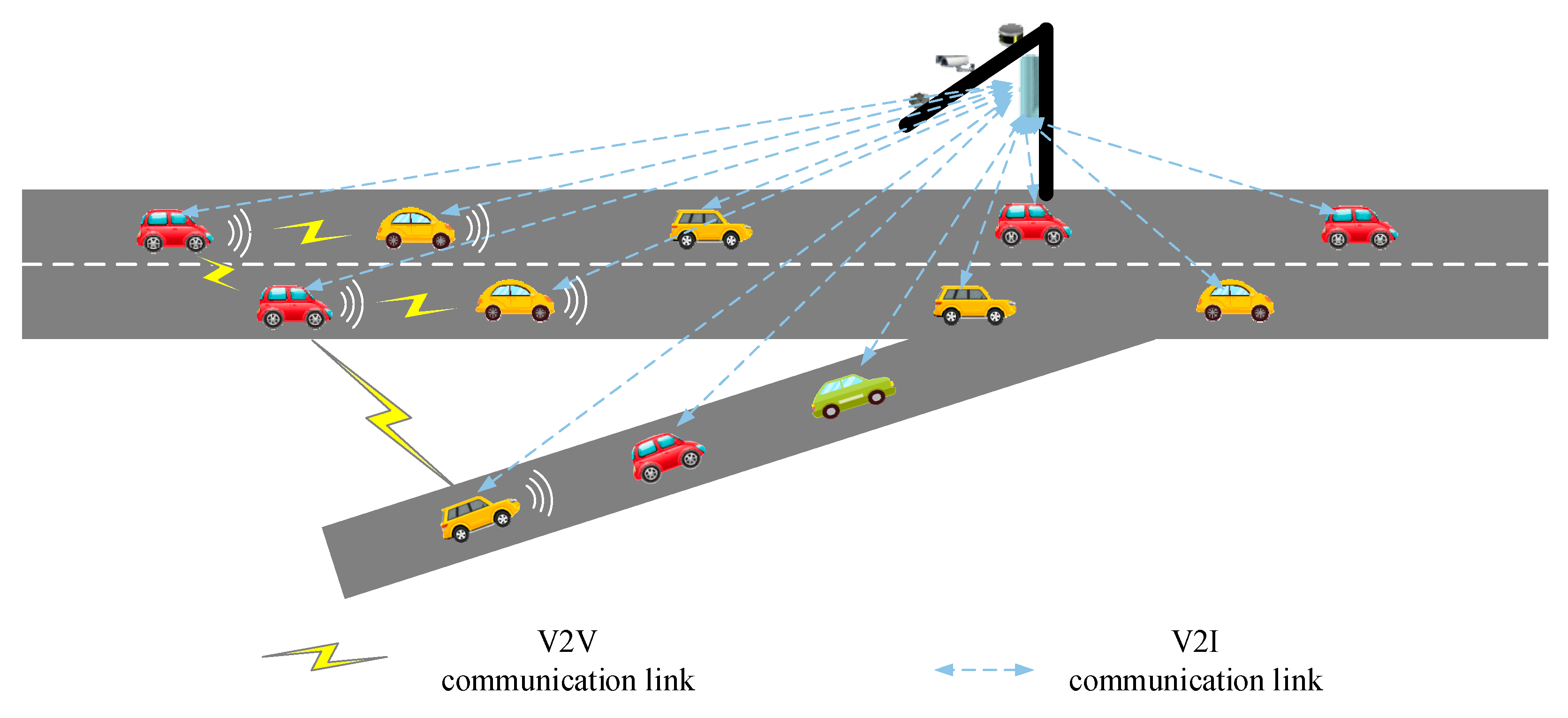
Multilane freeways are widely present in city transportation networks. In this study, we took a two-lane freeway with an on-ramp lane as an example, as shown in Figure 1. The mainstream traffic flow contains two lanes, and the incoming traffic flow is a single lane. CAVs merge at the intersection of the main lane and the ramp.
To simplify the entire model and facilitate optimization, we made the following assumptions for this scenario [25]:
- (1)
- All vehicles on the network are fully automated and equipped with V2V/V2I communication capabilities.
- (2)
- The lane-changing behavior is instantaneous. At the same time, we did not consider lateral vehicle control.
- (3)
- Communication delay and packet loss were not considered in this study.
- (4)
- Overtaking is not allowed throughout the merging process.
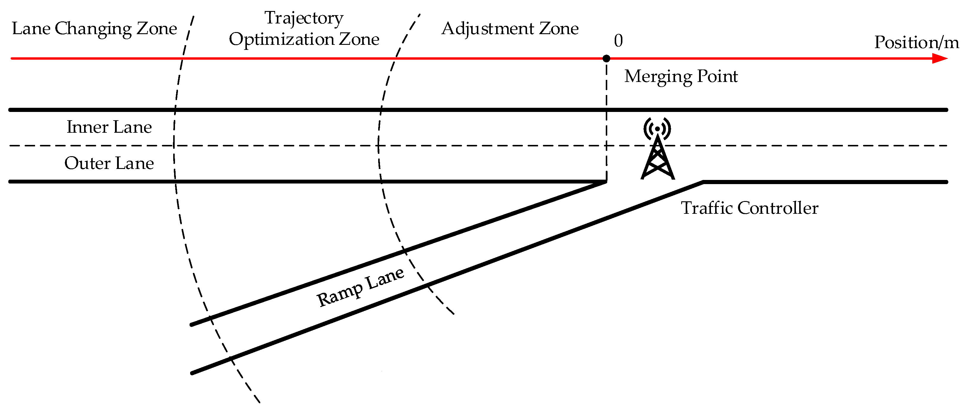
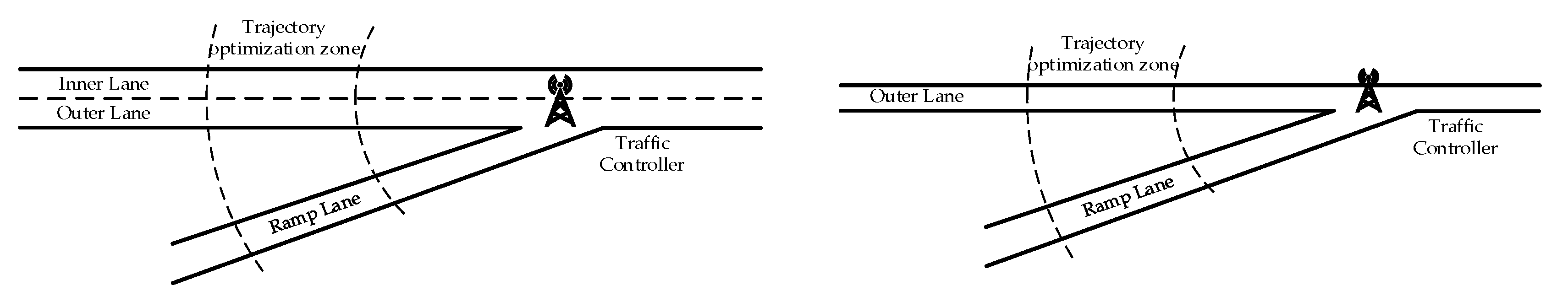
As shown in Figure 2, the two lanes of the mainstream traffic flow are called the Outer Lane and the Inner Lane, respectively, while the ramp lane is called the Ramp Lane. The Outer Lane is the lane close to the ramp, and the Inner Lane is the lane away from the ramp. The intersection of the mainstream traffic flow and the incoming traffic flow is defined as the merging point, which corresponds to the one-dimensional coordinate system’s origin. In this merging area, we set up a centralized control unit called traffic controller. CAVs periodically send their information, including vehicle ID, lane ID, position, speed, and acceleration, to the traffic controller. The traffic controller uses this information to control all input vehicles’ speed, acceleration, and lane-change behavior.
In our framework, the entire scenario was divided into three zones: lane-changing zone, trajectory optimization zone, and adjustment zone, where we mainly focused on the lane-changing and trajectory optimization zones. Lane-changing operation was only allowed in the lane-changing zone when the traffic controller ordered vehicles, while free lane changes were not allowed in other areas. In the trajectory optimization zone, the mainstream traffic vehicles and ramp vehicles adjusted their trajectories according to the corresponding optimal control model. Note that there was no additional optimization operation in the adjustment zone. The vehicle only needed to drive at the optimized speed and acceleration in the trajectory optimization zone before finally passing the ramp smoothly at a constant speed without collision.
3.1. Rule-Based Lane-Changing Strategy
The on-ramp of a freeway is an accident-prone traffic area. An on-ramp vehicle can easily collide with a mainline vehicle due to drivers’ lack of sight distance and vehicles’ inability to slow down in time during the merging process of on-ramp vehicles. We propose a rule-based lane-changing strategy to improve the merging efficiency and safety of freeways. The mainline vehicles change from the Outer Lane to the Inner Lane before the merge, providing sufficient space for the downstream merge.
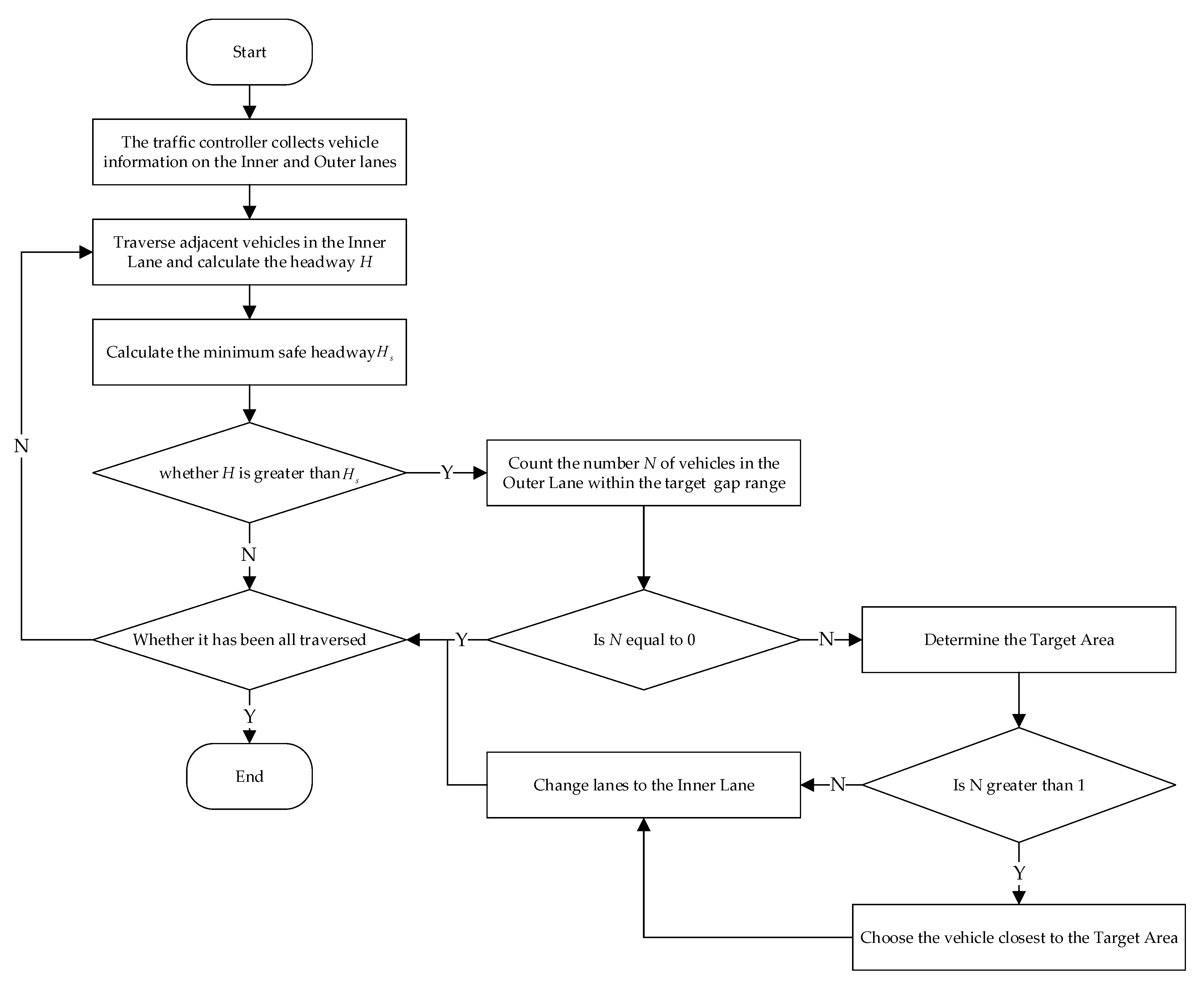
The proposed lane-changing strategy is mainly carried out in two steps: (1) find the appropriate lane-changing gap in the Inner Lane and (2) determine the lane-changing vehicle in the Outer Lane.
3.1.1. Determination of Target Gap for Lane Changing
The core problem of lane changing is finding a suitable entrance gap in the mainline’s adjacent lanes. When a vehicle changes lanes, the lane-changing may cause a rear-end or lateral collision with a vehicle in the target lane if the lane-changing vehicle’s speed is too high/low or the target gap estimation is unreasonable. Therefore, the lane-changing vehicle must meet a certain speed, and the target gap must meet the merging requirements so that the vehicle can safely merge into the adjacent lane.
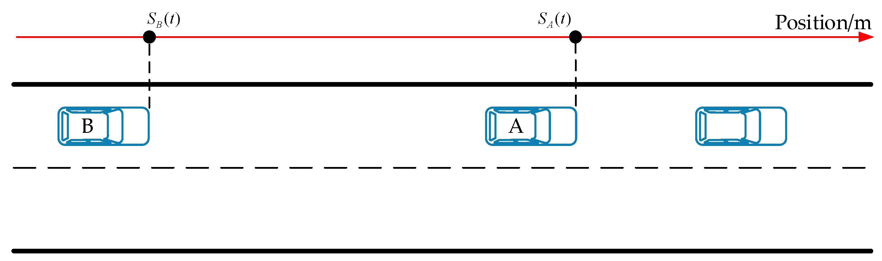
The method to determine the target gap for lane changing is as follows. First, we look for adjacent front and rear vehicles in the Inner Lane and then calculate the above-mentioned vehicles’ headway. The headway of the two adjacent vehicles at time t is calculated as Equation (1), where and are the position coordinates of the front and rear vehicles, respectively, at time t; is the speed of the following vehicle; and L is the length of the vehicle, as shown in Figure 3.
After that, it is necessary to judge whether the headway meets the requirements. A vehicle collision is likely to occur if adjacent vehicles’ headway in the Inner Lane is not enough. Therefore, before the vehicle in the Outer Lane changes lanes, it is necessary to determine whether the headway calculated in Equation (1) is less than the minimum safe headway for lane changing. In this study, the minimum safe headway was calculated as
where is the minimum safe headway between the front and rear two adjacent vehicles in the same lane and is the maximum speed.
The vehicle in the Outer Lane can be selected to change lanes if the headway of two adjacent vehicles in the Inner Lane satisfies Equation (3).
3.1.2. Determination of Lane-Changing Vehicle
After determining the target gap for lane changing of the Inner Lane, we need to select the appropriate vehicle in the Outer Lane to perform the lane-changing operation. The following principles should be followed to reduce acceleration and deceleration behavior and to ensure driving safety when choosing a lane-changing vehicle:
- (1)
- Do not consider vehicles outside the Outer Lane corresponding to the target gap for lane changing.
- (2)
- Preferentially select vehicles in the Outer Lane closest to the Target Area to change lanes.
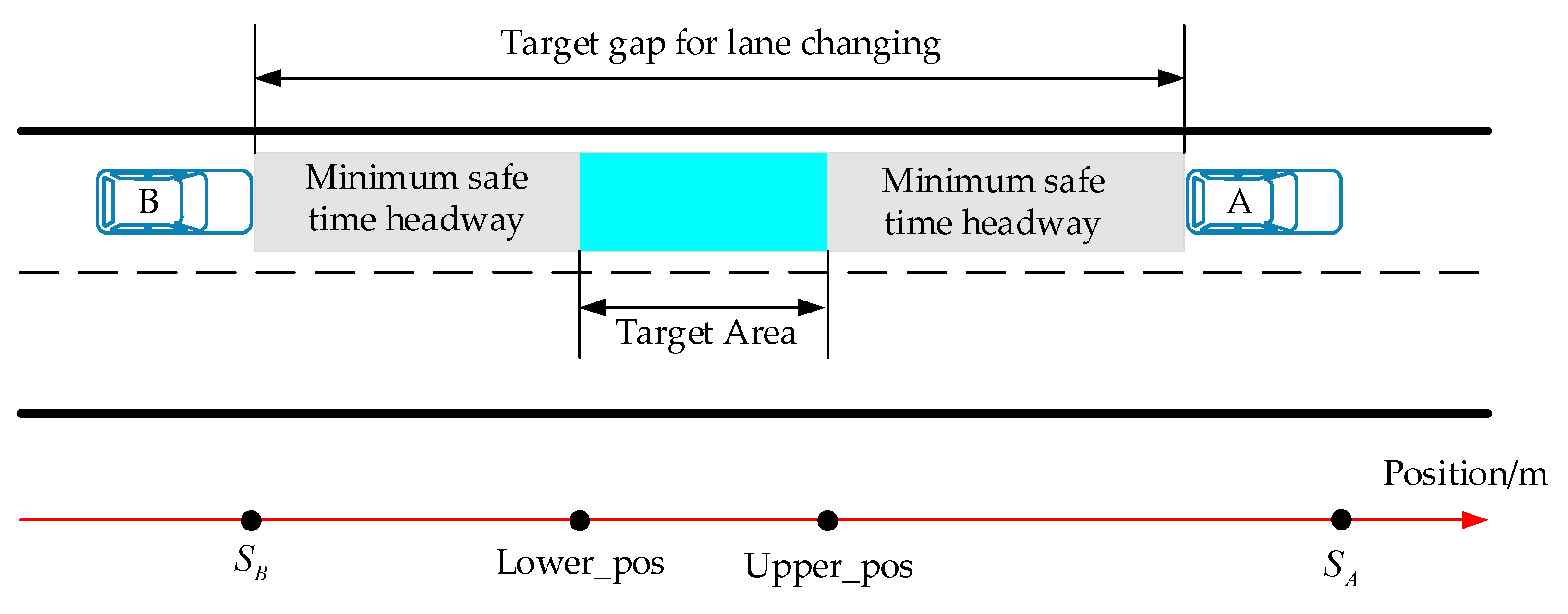
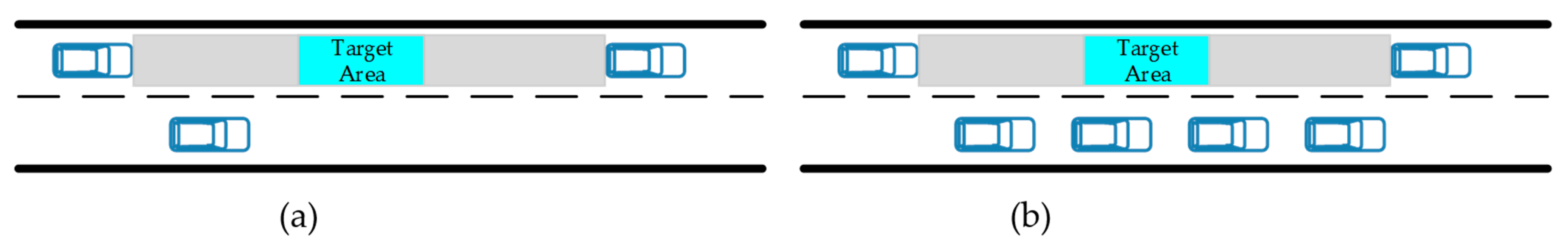
As shown in Figure 4, the target gap for lane changing is divided into three areas to ensure driving safety. The Target Area is the target arrival area of the lane-changing vehicles in the Outer Lane. The two points Lower_pos and Upper_pos on the coordinate axis represent the front and back boundaries of the Target Area, respectively, of the Target Area and are used as reference points for vehicle lane changing. The following vehicle in the Inner Lane needs to maintain a minimum safe headway from the Target Area to avoid rear-end collisions with vehicles in the Target Area. Of course, vehicles in the Target Area also need to maintain a minimum safe headway with the vehicle ahead in the Inner Lane.
Figure 5 shows the different situations of the Outer Lane within the target gap for lane changing. As shown in Figure 5a, when there is only one vehicle within the target gap for lane changing in the Outer Lane, this vehicle is selected as the lane-changing vehicle. It accelerates to the Target Area range and then changes lanes. As shown in Figure 5b, we preferred to select the vehicle closest to the Target Area as the lane-changing vehicle to reduce acceleration and deceleration behavior and to ensure driving safety when there are multiple vehicles within the target gap for lane changing in the Outer Lane.
The entire lane-changing process in the lane-changing zone is shown in Figure 6.
3.2. Trajectory Optimization
CAVs enter the trajectory optimization zone after completing the lane-changing operation. After that, vehicles are no longer allowed to change lanes, so we could convert the problem of merging the main road and the ramp into the merging problem of the Outer Lane of the mainline and the ramp, as shown in Figure 7.
In actual scenarios, vehicles on freeways and ramps enter continuously and in real-time. It is challenging to optimize all vehicles’ trajectories from the global perspective, so we decided to optimize the entering vehicles round by round in the trajectory optimization zone. In detail, the traffic controller starts to optimize all vehicles in the trajectory optimization zone when the first entering vehicle (which may be in the Outer Lane or the Ramp Lane) is about to leave in the trajectory optimization zone. After the optimization, the traffic controller starts to process the next round of incoming vehicles when the first vehicle of the next round of vehicles is about to leave the trajectory optimization area. We decided that we needed to remove the vehicles that are in the other lane during optimization without leaving the trajectory optimization zone in the last round of optimization.
Specifically, the traffic controller firstly collects all vehicles’ information in the trajectory optimization zone, including position, speed, and acceleration, when the traffic controller optimizes the trajectory of vehicles entering the Outer Lane and Ramp Lane. The traffic controller then uses the following control model for optimization to obtain each vehicle’s trajectory in the future seconds. The traffic controller controls each vehicle’s speed and acceleration according to the optimized results so that vehicles can pass the merge point without collision along the optimized trajectory.
Here, we borrowed the optimal control strategy in [26], where the trajectory optimization model is linear time discrete and each time step’s speed is used as a decision variable. The objective function of trajectory optimization is to maximize all vehicles’ speed while minimizing the acceleration rate in the trajectory optimization zone, as shown in Equation (4).
subject to
Constraints (5) and (6) are the limits of speed and acceleration, respectively. Constraints (7) and (8) are vehicle dynamics equations. Constraint (9) means that the distance between two adjacent vehicles in the same lane must meet the minimum safety gap requirement. Constraint (10) is imposed onto the last optimization time step to ensure that the outside lane and ramp vehicles maintain a safe distance after the optimization is completed.
Table 1 details the parameters and symbol descriptions involved in the trajectory optimization model.
4. Simulation Results and Case Study
4.1. Simulation Results and Visualization
To verify the model’s validity, we first established the ramp merging scenario in SUMO and simulated the proposed model. In our simulation, the total length of the mainline was 1000 m, of which the length of the lane-changing zone was 350 m, the length of the trajectory optimization zone was 300 m, and the length of the adjustment zone was 250 m; refer to [10,26].
The simulation parameters are shown in Table 2. In the simulation, we limited the maximum traffic flow of the main line to 2000 vehicles per hour, and the maximum traffic flow of the ramp to 1000 vehicles per hour; refer to [10]. At the beginning of the simulation, the vehicle enters the simulation scenario with random speed and acceleration that meets the parameters shown in Table 2. When vehicles enter the lane-changing zone, the traffic controller controls the vehicle to change lanes. Vehicles then enter the trajectory optimization zone, and the traffic controller specifies the speed and acceleration for the vehicle before it passes the merging point.
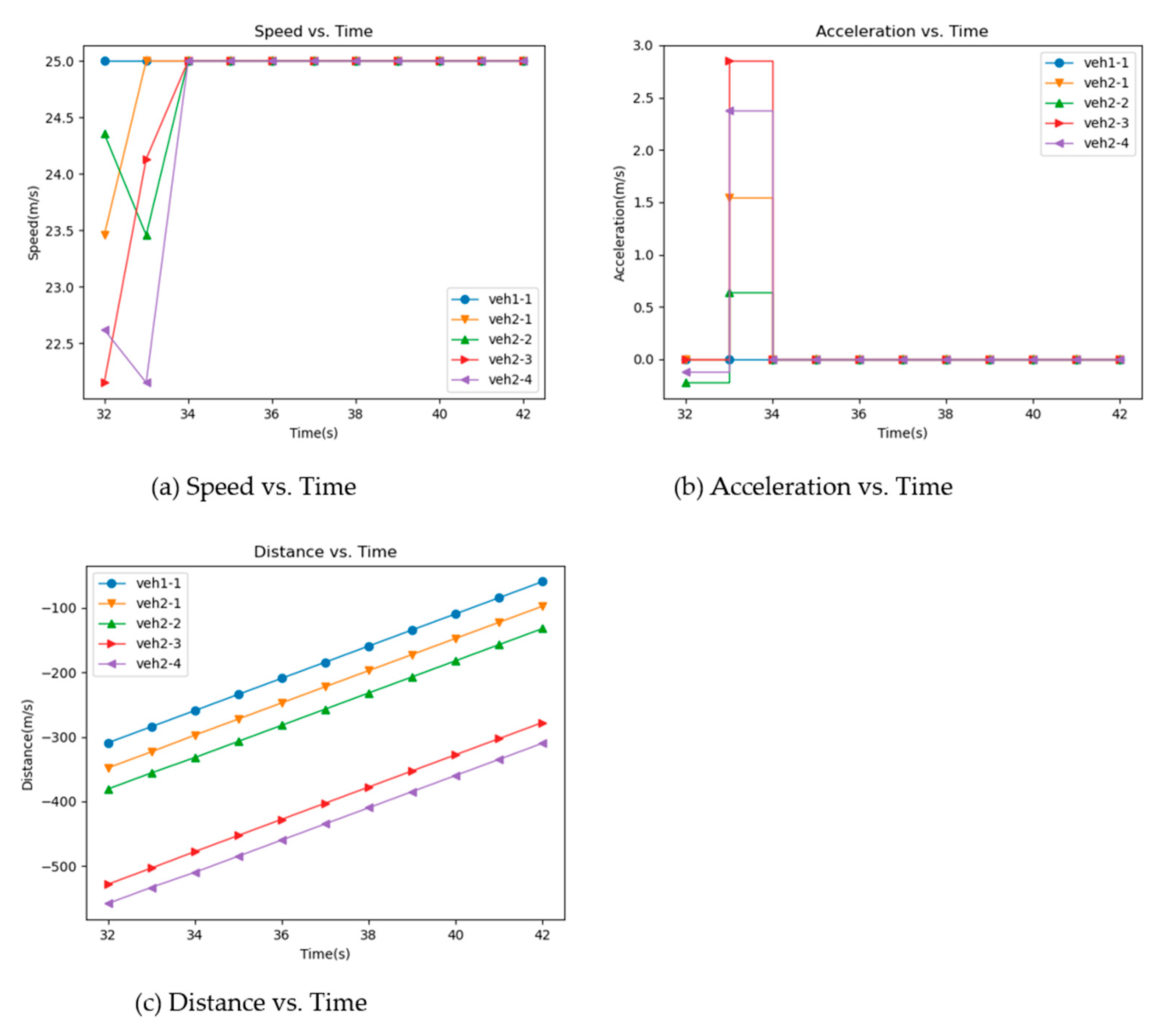
In the trajectory optimization zone, optimization was performed while the vehicle filled the trajectory optimization zone. The first optimization results are shown in Figure 8, where veh1-1 represents the first vehicle in the Outer Lane, veh2-1 represents the first vehicle in the Ramp Lane, and so on.
The optimization results showed that the vehicles traveled at different speeds before optimization. The vehicles maintained a safe distance from the front and rear vehicles through acceleration and deceleration during the optimization process. At the last optimization time step, all vehicles drove at the maximum speed, and the distance–time curve showed that a safe driving gap could be maintained between the same and different lanes after optimization.
We took the first optimization results as an example to make a brief analysis. In 32 s, the traffic controller started to optimize the vehicles in the trajectory optimization zone. Veh1-1 was located on the main road, and veh2-1, veh2-2, veh2-3, and veh2-4 were located on the ramp. In 32–33 s, veh2-2 and veh2-4 slowed down to maintain the distance with the vehicle in front. At 34 s, all vehicles reached their maximum speed and passed the merging point at a constant speed.
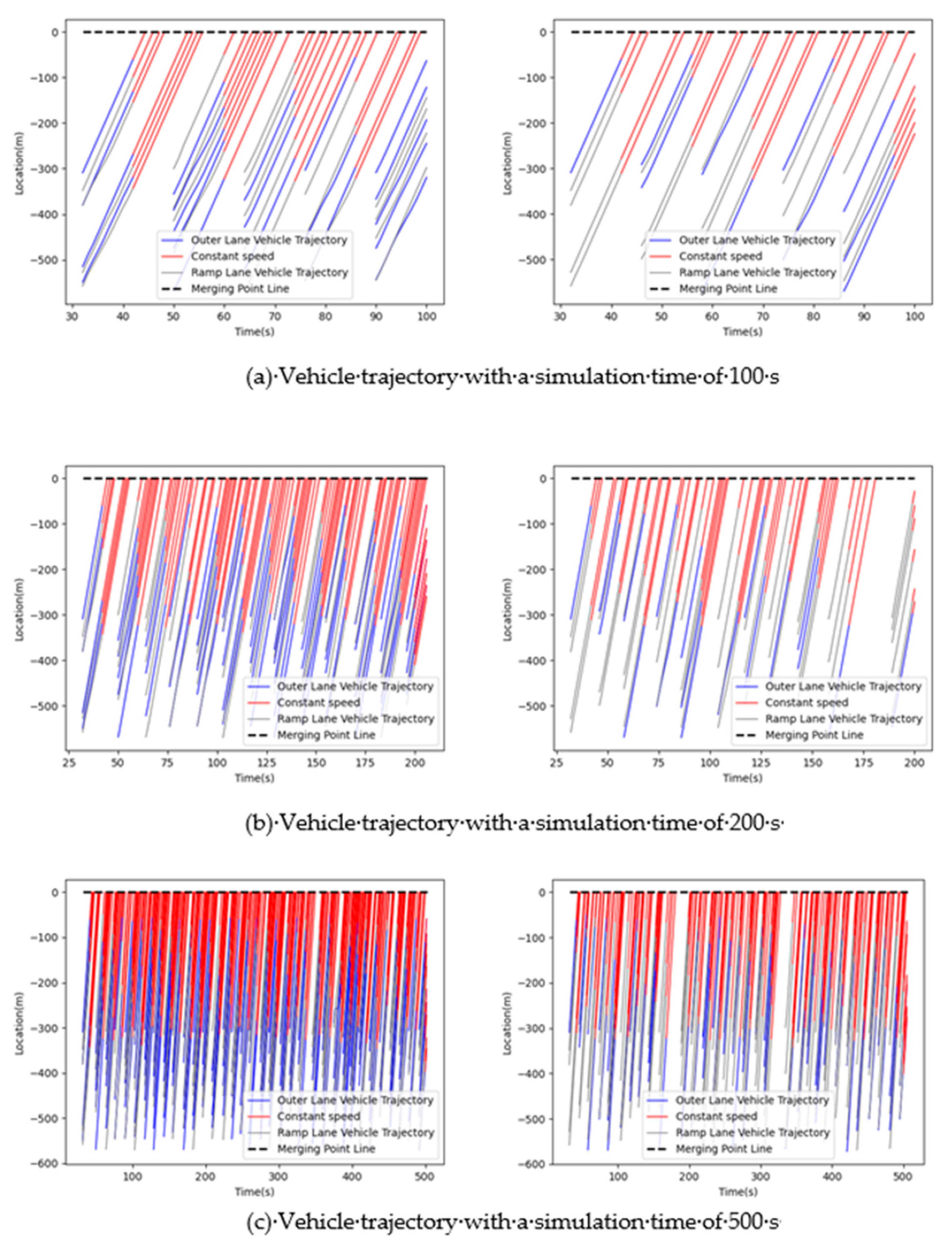
Additionally, all vehicles’ trajectories in the Outer Lane and Ramp Lane are visualized in Figure 9. The gray lines in the figure represent vehicles in the Ramp Lane. The blue lines represent vehicles in the Outer Lane, and the red lines mean that vehicles’ trajectory optimization is over. Vehicles start to drive at a constant speed and finally pass through the merge point. In Figure 9—left, all vehicles had not changed lanes before merging. As the simulation time increased, the number of vehicles optimized in the trajectory optimization zone increased, which increased the delay time and driving risk. In comparison, some vehicles changed lanes from the Outer Lane to Inner Lane in the lane-changing zone before merging in Figure 9—right, reducing the delay caused by deceleration and increasing the travel speed.
4.2. Case Study
To further verify the model proposed above, we considered three different cases and tested four different demand levels of 800, 1200, 1600, and 2000 veh/h; three different demand splits of 50–50, 65–35, and 80–20; and three different safety time gaps of 1.0, 1.2, and 1.5 s according to [25]. The simulation time for each scenario was 3600 s. Additionally, we evaluated the model’s effectiveness through three indicators: number of stops (if the speed was less than 1 m/s, it was regarded as stopping), average delay time, and average speed.
Three different control cases are as follows:
- Case 0: do nothing. The vehicles travelled freely without any optimization control. This case adopted SUMO’s default driving model.
- Case 1: only trajectory optimization. Only the trajectory optimization and adjustment zones were set, and the vehicles were optimized after entering the trajectory optimization zone.
- Case 2: lane-changing strategy and trajectory optimization. With the addition of lane-changing strategy, the vehicle can change lanes in the lane-changing zone, and then enter the trajectory optimization zone for trajectory optimization.
The simulation results under different demands are shown in Table 3, Table 4 and Table 5. Overall, for the three different demand splits, Case 1 was better than Case 0 on the whole, and Case 2 outperformed Case 1.
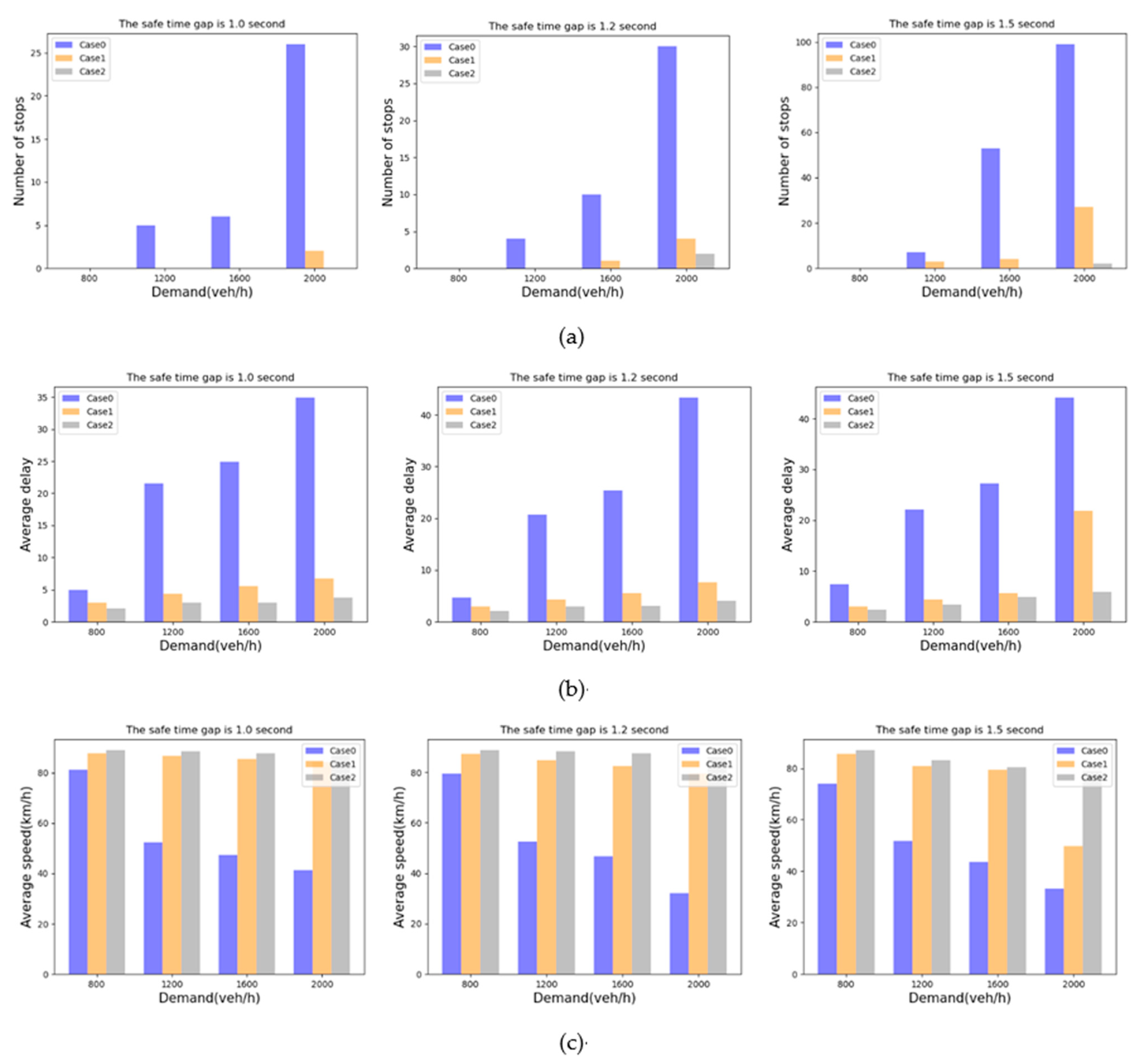
Let us take the 50–50 demand split as an example; see Figure 10. As shown in Figure 10a, vehicles may have stopped because they adjust their speed to ensure a safe gap between vehicles. Unlike Case 0 and Case 1, the cars of Case 2 would basically not stop when the safety time gap was 1.0 s during the simulation. This advantage of Case 2 became more evident as the safety time gap and traffic volume increased. At 800 veh/h, there was no apparent difference between the three cases in terms of average delay and average speed. With the increase of freeway and ramp traffic flow, the difference in performance indicators was gradually significant. Significantly, at 2000 veh/h, the average delay of Case 1 was reduced by about 70.3%, and the average speed was approximately doubled compared to Case 0. The average delay of Case 2 was reduced by about 38.3%, and the average speed was increased by about 18.2% compared with Case 1.
Additionally, the average speed and average delay of Case 0 were not stable. With the change of mainline traffic flow and ramp traffic flow, the average speed and average delay significantly changed, and the average speed and delay changes of Case 1 and 2 were relatively stable due to the vehicle’s trajectory optimization. Furthermore, due to the addition of the lane-changing strategy, the average delay of Case 2 was lower, and traffic flow and safety time gaps had little impact on the average speed. Therefore, compared with Case 1 and Case 0, the merging model based on the lane-changing strategy improved efficiency.
As with the 50–50 demand, the number of stops, average delay, and average speed, split of Case 2 always outperformed those of Case 1 and Case 0, as shown in Table 4 and Table 5. As the demand increased, the performance difference became greater and more obvious. In addition, in the 80–20 demand split, the performance of the three cases was greatly improved when compared to the 50–50 and 65–35 splits. The ramp traffic decreased and vehicles experienced less merging interactions, resulting in lower travel delays and smaller numbers of stops when compared to the more even demand splits.
5. Conclusions
In this paper, we proposed a lane-changing strategy with collaborative merging for CAVs in a multilane freeway on-ramp area under the V2X network. In this environment, vehicles and the traffic controller can exchange information with each other in time, and we divided the freeway into three zones. In the lane-changing zone, we proposed a rule-based lane-changing strategy that enabled vehicles to safely change lanes without affecting other vehicles. Meanwhile, we established a linear time discrete model that could optimize vehicles’ trajectories in real-time. All these proposed models and strategies were implemented in SUMO and Python. We compared three different cases under different demands, safety time gaps, and demand splits. The simulation results showed that the merging model we proposed based on the lane-changing strategy had a good performance in terms of the number of stops, average delay, and average speed.
In future work, we will consider the lane-changing and merging operations of vehicles in an on-ramp area under a 5G cellular network environment and consider the communication delay between the traffic controller and vehicles, which is necessary for vehicles traveling on a freeway.
Author Contributions
Y.S. and H.Y. formulated the problems and proposed the research framework; H.Y. and Y.G. conceived the methodologies and designed the experiments; H.Y. and Z.Y. performed the experiments; Y.S. and H.Y. contributed to the editing of the paper. All authors have read and agreed to the published version of the manuscript.
Funding
This research was funded by the China National Key Research and Development Program (NO.2018YFE0197700).
Acknowledgments
This research was derived from the Advanced Driving Use Case in the 5G-MOBIX project. The 5G-MOBIX project has received funding from the European Union’s Horizon 2020 program. The content only reflects the author’s views.
Conflicts of Interest
The authors declare no conflict of interest.
References
- Ding, J.; Li, L.; Peng, H.; Zhang, Y. A Rule-Based Cooperative Merging Strategy for Connected and Automated Vehicles. IEEE. Trans. Intell. Transp. 2020, 21, 3436–3446. [Google Scholar] [CrossRef]
- Cao, W.; Mukai, M.; Kawabe, T.; Nishira, H.; Fujiki, N. Cooperative vehicle path generation during merging using model predictive control with real-time optimization. Control Eng. Pract. 2015, 34, 98–105. [Google Scholar] [CrossRef]
- Xu, H.; Feng, S.; Zhang, Y.; Li, L. A Grouping-Based Cooperative Driving Strategy for CAVs Merging Problems. IEEE Trans. Veh. Technol. 2019, 68, 6125–6136. [Google Scholar] [CrossRef]
- Rios-Torres, J.; Malikopoulos, A.; Pisu, P. Online Optimal Control of Connected Vehicles for Efficient Traffic Flow at Merging Roads; IEEE: Piscataway, NJ, USA, 2015; pp. 2432–2437. [Google Scholar]
- Wang, Y.; Li, X.; Yao, H. Review of trajectory optimisation for connected automated vehicles. IET Intell. Transp. Syst. 2019, 13, 580–586. [Google Scholar] [CrossRef]
- Guo, Q.; Li, L.; Jeff Ban, X. Urban traffic signal control with connected and automated vehicles: A survey. Transp. Res. Part C Emerg. Technol. 2019, 101, 313–334. [Google Scholar] [CrossRef]
- Olia, A.; Abdelgawad, H.; Abdulhai, B.; Razavi, S.N. Assessing the Potential Impacts of Connected Vehicles: Mobility, Environmental, and Safety Perspectives. J. Intell. Transport. Syst. 2015, 20, 229–243. [Google Scholar] [CrossRef]
- Dong, C.; Wang, H.; Li, Y.; Liu, Y.; Chen, Q. Economic comparison between vehicle-to-vehicle (V2V) and vehicle-to-infrastructure (V2I) at freeway on-ramps based on microscopic simulations. IET Intell. Transp. Syst. 2019, 13, 1726–1735. [Google Scholar] [CrossRef]
- Lozano Domínguez, J.M.; Mateo Sanguino, T.J. Review on V2X, I2X, and P2X Communications and Their Applications: A Comprehensive Analysis over Time. Sensors 2019, 19, 2756. [Google Scholar] [CrossRef] [Green Version]
- Hu, X.; Sun, J. Trajectory optimization of connected and autonomous vehicles at a multilane freeway merging area. Transp. Res. Part C Emerg. Technol. 2019, 101, 111–125. [Google Scholar] [CrossRef]
- Liu, H.; Kan, X.D.; Shladover, S.E.; Lu, X.; Ferlis, R.E. Modeling impacts of Cooperative Adaptive Cruise Control on mixed traffic flow in multi-lane freeway facilities. Transp. Res. Part C Emerg. Technol. 2018, 95, 261–279. [Google Scholar] [CrossRef]
- Xiao, W.; Cassandras, C.G.; Belta, C. Decentralized Optimal Control in Multi-lane Merging for Connected and Automated Vehicles. In Proceedings of the 2020 IEEE 23rd International Conference on Intelligent Transportation Systems (ITSC), Rhodes, Greece, 20–23 September 2020. [Google Scholar]
- Zhang, L.; Wang, S.; Chen, C.; Yang, M.; She, X. Modeling Lane-Change Risk in Urban Expressway Off-Ramp Area Based on Naturalistic Driving Data. J. Test. Eval. 2020, 48, 20190269. [Google Scholar] [CrossRef]
- An, H.; Jung, J. Design of a Cooperative Lane Change Protocol for a Connected and Automated Vehicle Based on an Estimation of the Communication Delay. Sensor 2018, 18, 3499. [Google Scholar] [CrossRef] [Green Version]
- Cheng, S.; Wang, C.; Zhang, S.; Zong, R.; Deng, X. Study on control strategy for personalised lane-change on highway. J. Eng. 2018, 2018, 1724–1730. [Google Scholar] [CrossRef]
- Rios-Torres, J.; Malikopoulos, A.A. A Survey on the Coordination of Connected and Automated Vehicles at Intersections and Merging at Highway On-Ramps. IEEE. Trans. Intell. Transp. 2017, 18, 1066–1077. [Google Scholar] [CrossRef]
- Ye, F.; Guo, J.; Kim, K.J.; Orlik, P.V.; Ahn, H.; Di Cairano, S.; Barth, M.J. Bi-Level Optimal Edge Computing Model for On-Ramp Merging in Connected Vehicle Environment; IEEE: Piscataway, NJ, USA, 2019; pp. 2005–2011. [Google Scholar]
- Ding, J.; Peng, H.; Zhang, Y.; Li, L. Penetration effect of connected and automated vehicles on cooperative on-ramp merging. IET Intell. Transp. Syst. 2020, 14, 56–64. [Google Scholar] [CrossRef]
- Pei, H.; Feng, S.; Zhang, Y.; Yao, D. A Cooperative Driving Strategy for Merging at On-Ramps Based on Dynamic Programming. IEEE Trans. Veh. Technol. 2019, 68, 11646–11656. [Google Scholar] [CrossRef]
- Jing, S.; Hui, F.; Zhao, X.; Rios-Torres, J.; Khattak, A.J. Cooperative Game Approach to Optimal Merging Sequence and on-Ramp Merging Control of Connected and Automated Vehicles. IEEE Trans. Intell. Transp. 2019, 20, 4234–4244. [Google Scholar] [CrossRef]
- Min, H.; Fang, Y.; Wang, R.; Li, X.; Xu, Z.; Zhao, X. A Novel On-Ramp Merging Strategy for Connected and Automated Vehicles Based on Game Theory. J. Adv. Transp. 2020, 2020, 1–11. [Google Scholar] [CrossRef]
- Milanes, V.; Godoy, J.; Villagra, J.; Perez, J. Automated On-Ramp Merging System for Congested Traffic Situations. IEEE. Trans. Intell. Transp. 2011, 12, 500–508. [Google Scholar] [CrossRef] [Green Version]
- Ntousakis, I.A. Assessing the Impact of a Cooperative Merging System on Highway Traffic Using a Microscopic Flow Simulator; ASME: New York, NY, USA, 2014; pp. 1–10. [Google Scholar]
- Jin, Q.; Wu, G.; Boriboonsomsin, K.; Barth, M. Platoon-Based Multi-Agent Intersection Management for Connected Vehicle; IEEE: Piscataway, NJ, USA, 2013; pp. 1462–1467. [Google Scholar]
- Letter, C.; Elefteriadou, L. Efficient control of fully automated connected vehicles at freeway merge segments. Transp. Res. Part C Emerg. Technol. 2017, 80, 190–205. [Google Scholar] [CrossRef]
- Xie, Y.; Zhang, H.; Gartner, N.H.; Arsava, T. Collaborative merging strategy for freeway ramp operations in a connected and autonomous vehicles environment. J. Intell. Transp. Syst. 2016, 21, 136–147. [Google Scholar] [CrossRef]
Figure 1.
Schematic illustration of a typical two-lane freeway merging area.

Figure 2.
Regional division of ramp area on a two-lane freeway.

Figure 3.
Schematic diagram of the position of target vehicle at time t.

Figure 4.
Schematic diagram of the target gap for lane changing in the lane-changing zone.

Figure 5.
Vehicle conditions in the Outer Lane within the target gap for lane changing: (a) only one vehicle exists; (b) there are multiple vehicles.
Figure 5.
Vehicle conditions in the Outer Lane within the target gap for lane changing: (a) only one vehicle exists; (b) there are multiple vehicles.

Figure 6.
Flow chart of vehicle lane changing in the lane-changing zone.

Figure 7.
Simplified diagram of the trajectory optimization zone.

Figure 8.
The first optimization in the trajectory optimization zone.

Figure 9.
Schematic diagram of vehicle trajectory. The left side is the scenario without lane changing, and the right side is the lane-changing scenario.
Figure 9.
Schematic diagram of vehicle trajectory. The left side is the scenario without lane changing, and the right side is the lane-changing scenario.

Figure 10.
Comparison of different cases under different demands and safety time gaps: (a) The number of stops, (b) average delay, and (c) average speed.
Figure 10.
Comparison of different cases under different demands and safety time gaps: (a) The number of stops, (b) average delay, and (c) average speed.


Table 1.
Parameter and symbol description of the trajectory optimization model.
| Parameter | Unit | Description |
|---|---|---|
| The speed of the n-th vehicle on lane l at time step t | ||
| The acceleration of the n-th vehicle on lane l at time step t | ||
| The position of the n-th vehicle on lane l at time step t | ||
| Maximum speed allowed | ||
| Minimum acceleration allowed | ||
| Maximum acceleration allowed | ||
| , | Weight coefficient | |
| The minimum safety time gap | ||
| Time interval of trajectory optimization zone | ||
| Timestep | ||
| Lane identifier (Outer Lane is 1 and Ramp Lane is 2) | ||
| The index of each vehicle in the corresponding lane | ||
| Total number of vehicles in the lane | ||
| Total simulation step for trajectory optimization | ||
| Index of the vehicle in the Outer Lane | ||
| Index of the vehicle in the Ramp Lane | ||
| T | s | Total simulation time |
Table 2.
Simulation parameters.
| Parameter | Unit | Value |
|---|---|---|
| 25 | ||
| , | −5, 5 | |
| , | - | 1 |
| s | 1.5 | |
| 1.0 | ||
| 10 | ||
| T | 100 | |
| L | m | 5 |
Table 3.
Simulation results under the 50–50 demand.
| Number of Stops | Average Delay (s) | Average Speed (km/h) | |||||||||||
|---|---|---|---|---|---|---|---|---|---|---|---|---|---|
| Demand (veh/h) | Demand (veh/h) | Demand (veh/h) | |||||||||||
| 800 | 1200 | 1600 | 2000 | 800 | 1200 | 1600 | 2000 | 800 | 1200 | 1600 | 2000 | ||
| 1.0 | Case 0 | 0 | 5 | 6 | 26 | 4.93 | 21.56 | 24.92 | 34.90 | 81.2 | 52.4 | 47.3 | 41.2 |
| Case 1 | 0 | 0 | 0 | 2 | 3.03 | 4.35 | 5.59 | 6.79 | 87.9 | 86.8 | 85.5 | 84.3 | |
| Case 2 | 0 | 0 | 0 | 0 | 2.12 | 2.96 | 3.02 | 3.74 | 89.0 | 88.6 | 87.9 | 87.1 | |
| 1.2 | Case 0 | 0 | 4 | 10 | 30 | 4.73 | 20.67 | 25.40 | 43.30 | 79.6 | 52.5 | 46.6 | 32.2 |
| Case 1 | 0 | 0 | 1 | 4 | 3.02 | 4.35 | 5.59 | 7.66 | 87.4 | 84.9 | 82.6 | 79.4 | |
| Case 2 | 0 | 0 | 0 | 2 | 2.13 | 2.97 | 3.05 | 4.10 | 88.8 | 88.3 | 87.5 | 86.2 | |
| 1.5 | Case 0 | 0 | 7 | 53 | 99 | 7.42 | 22.06 | 27.23 | 44.12 | 74.0 | 51.7 | 43.5 | 33.1 |
| Case 1 | 0 | 3 | 4 | 27 | 3.03 | 4.36 | 5.69 | 21.86 | 85.6 | 80.8 | 79.3 | 49.7 | |
| Case 2 | 0 | 0 | 0 | 2 | 2.39 | 3.45 | 4.93 | 5.94 | 87.0 | 83.0 | 80.4 | 78.9 | |
Table 4.
Simulation results under the 65–35 demand.
| Number of Stops | Average Delay (s) | Average Speed (km/h) | |||||||||||
|---|---|---|---|---|---|---|---|---|---|---|---|---|---|
| Demand (veh/h) | Demand (veh/h) | Demand (veh/h) | |||||||||||
| 800 | 1200 | 1600 | 2000 | 800 | 1200 | 1600 | 2000 | 800 | 1200 | 1600 | 2000 | ||
| 1.0 | Case 0 | 0 | 0 | 1 | 24 | 3.02 | 4.72 | 7.32 | 32.09 | 84.6 | 81.9 | 72.3 | 40.6 |
| Case 1 | 0 | 0 | 0 | 0 | 3.07 | 3.55 | 4.46 | 5.24 | 88.8 | 88.4 | 87.9 | 87.2 | |
| Case 2 | 0 | 0 | 0 | 0 | 2.61 | 2.82 | 3.18 | 3.37 | 89.3 | 89.0 | 88.5 | 88.0 | |
| 1.2 | Case 0 | 0 | 0 | 9 | 16 | 2.51 | 5.28 | 25.26 | 45.72 | 84.3 | 77.4 | 47.0 | 32.5 |
| Case 1 | 0 | 0 | 0 | 2 | 3.07 | 3.55 | 4.31 | 7.24 | 88.6 | 88.1 | 87.4 | 86.4 | |
| Case 2 | 0 | 0 | 0 | 0 | 2.61 | 2.83 | 3.19 | 3.39 | 89.2 | 88.7 | 88.2 | 87.5 | |
| 1.5 | Case 0 | 1 | 3 | 9 | 31 | 2.71 | 5.23 | 27.48 | 43.62 | 83.9 | 74.1 | 44.3 | 33.1 |
| Case 1 | 0 | 0 | 0 | 8 | 3.08 | 3.55 | 5.47 | 10.17 | 88.2 | 87.1 | 85.3 | 76.2 | |
| Case 2 | 0 | 0 | 0 | 0 | 2.61 | 2.84 | 3.28 | 3.50 | 89.1 | 88.2 | 86.1 | 83.3 | |
Table 5.
Simulation results under the 80–20 demand.
| Number of Stops | Average Delay (s) | Average Speed (km/h) | |||||||||||
|---|---|---|---|---|---|---|---|---|---|---|---|---|---|
| Demand (veh/h) | Demand (veh/h) | Demand (veh/h) | |||||||||||
| 800 | 1200 | 1600 | 2000 | 800 | 1200 | 1600 | 2000 | 800 | 1200 | 1600 | 2000 | ||
| 1.0 | Case 0 | 0 | 0 | 0 | 0 | 2.14 | 2.81 | 4.36 | 6.22 | 85.1 | 83.8 | 81.3 | 77.1 |
| Case 1 | 0 | 0 | 0 | 0 | 2.62 | 3.00 | 3.38 | 4.92 | 88.7 | 88.2 | 88.1 | 87.9 | |
| Case 2 | 0 | 0 | 0 | 0 | 2.67 | 2.75 | 2.76 | 3.03 | 89.3 | 88.9 | 88.4 | 88.0 | |
| 1.2 | Case 0 | 0 | 0 | 0 | 8 | 4.19 | 3.08 | 4.89 | 8.50 | 84.9 | 84.0 | 80.2 | 70.6 |
| Case 1 | 0 | 0 | 0 | 0 | 2.62 | 4.92 | 6.00 | 6.38 | 88.5 | 88.0 | 87.9 | 87.6 | |
| Case 2 | 0 | 0 | 0 | 0 | 2.68 | 2.75 | 2.76 | 3.07 | 89.2 | 88.9 | 88.2 | 87.7 | |
| 1.5 | Case 0 | 0 | 0 | 0 | 26 | 4.32 | 3.15 | 6.96 | 21.07 | 84.6 | 82.4 | 77.7 | 49.8 |
| Case 1 | 0 | 0 | 0 | 1 | 2.62 | 6.01 | 6.39 | 4.92 | 88.3 | 87.5 | 86.8 | 85.1 | |
| Case 2 | 0 | 0 | 0 | 0 | 3.08 | 2.76 | 2.76 | 2.69 | 89.2 | 88.9 | 88.0 | 87.1 | |
Publisher’s Note: MDPI stays neutral with regard to jurisdictional claims in published maps and institutional affiliations. |
© 2021 by the authors. Licensee MDPI, Basel, Switzerland. This article is an open access article distributed under the terms and conditions of the Creative Commons Attribution (CC BY) license (https://creativecommons.org/licenses/by/4.0/).
Share and Cite
MDPI and ACS Style
Shi, Y.; Yu, H.; Guo, Y.; Yuan, Z. A Collaborative Merging Strategy with Lane Changing in Multilane Freeway On-Ramp Area with V2X Network. Future Internet 2021, 13, 123. https://0-doi-org.brum.beds.ac.uk/10.3390/fi13050123
AMA Style
Shi Y, Yu H, Guo Y, Yuan Z. A Collaborative Merging Strategy with Lane Changing in Multilane Freeway On-Ramp Area with V2X Network. Future Internet. 2021; 13(5):123. https://0-doi-org.brum.beds.ac.uk/10.3390/fi13050123
Chicago/Turabian StyleShi, Yanjun, Hao Yu, Yijia Guo, and Zhiheng Yuan. 2021. "A Collaborative Merging Strategy with Lane Changing in Multilane Freeway On-Ramp Area with V2X Network" Future Internet 13, no. 5: 123. https://0-doi-org.brum.beds.ac.uk/10.3390/fi13050123
Note that from the first issue of 2016, this journal uses article numbers instead of page numbers. See further details here.