Article

Quantifying the Density of mmWave NR Deployments for Provisioning Multi-Layer VR Services

1
Department of Applied Probability and Informatics, Peoples’ Friendship University of Russia (RUDN University), 117198 Moscow, Russia
2
Department of Applied Economics, Peoples’ Friendship University of Russia (RUDN University), 117198 Moscow, Russia
3
Faculty of Information Technology and Communication Sciences, Tampere University, 33720 Tampere, Finland
4
Federal Research Center “Computer Science and Control” of Russian Academy of Sciences, 119333 Moscow, Russia
*
Author to whom correspondence should be addressed.
Future Internet 2021, 13(7), 185; https://0-doi-org.brum.beds.ac.uk/10.3390/fi13070185
Submission received: 28 June 2021 / Revised: 14 July 2021 / Accepted: 17 July 2021 / Published: 20 July 2021
(This article belongs to the Special Issue 5G Wireless Communication Networks)

Abstract

:
The 5G New Radio (NR) technology operating in millimeter wave (mmWave) frequency band is designed for support bandwidth-greedy applications requiring extraordinary rates at the access interface. However, the use of directional antenna radiation patterns, as well as extremely large path losses and blockage phenomenon, requires efficient algorithms to support these services. In this study, we consider the multi-layer virtual reality (VR) service that utilizes multicast capabilities for baseline layer and unicast transmissions for delivering an enhanced experience. By utilizing the tools of stochastic geometry and queuing theory we develop a simple algorithm allowing to estimate the deployment density of mmWave NR base stations (BS) supporting prescribed delivery guarantees. Our numerical results show that the highest gains of utilizing multicast service for distributing base layer is observed for high UE densities. Despite of its simplicity, the proposed multicast group formation scheme operates close to the state-of-the-art algorithms utilizing the widest beams with longest coverage distance in approximately 50–70% of cases when UE density is λ 0.3 . Among other parameters, QoS profile and UE density have a profound impact on the required density of NR BSs while the effect of blockers density is non-linear having the greatest impact on strict QoS profiles. Depending on the system and service parameters the required density of NR BSs may vary in the range of 20–250 BS/km2.

1. Introduction

Nowadays, 3rd Generation Partnership Project (3GPP) has already finished the major steps in New Radio (NR) technology standardization in Release 15 and Release 16 [1]. Operating in both microwave (μWave) and millimeter wave (mmWave) bands these systems promise to deliver extraordinary rates to the air interface [2]. The current focus of both 3GPP and the research community is shifting towards delivering value-added services on top of this new radio access technology (RAT) with multicasting capabilities being on the list of tasks for 2020–2021 Release 17 agenda [3].
NR technologies come with several unique solutions. To compensate for high propagation losses and efficiently suppress interference NR systems heavily rely on antenna arrays forming directional radiation patterns, especially, at NR BSs [4]. The latter induces the inherent trade-off for multicast service, i.e., the use of smaller half-power beamwidths (HPBW) allows expanding the coverage of a single mmWave base station (BS) due to higher gain while, at the same time, decreases the number of user equipment (UE) devices that can be served in a single transmission. Furthermore, it has been shown in [5] the presence of multicast traffic negatively affects the service performance of unicast one making provisioning of services requiring both types of transmissions a complex problem. Thus, the choice of the optimal density of mmWave BSs is a non-trivial task that becomes even more complicated when advanced services need to be provisioned.
In this paper, we consider multi-layer virtual reality (VR). This application inherently requires both multicast and unicast network services for efficient provisioning in mmWave NR systems presenting extremely challenging conditions for mmWave NR systems. To the best of the authors’ knowledge, most of the studies performed so far for multi-layer multicast/unicast services concentrated on optimizing an already provisioned deployment for given traffic conditions. However, for network operators, the question of estimating the required density of mmWave NR BSs for a given stochastic traffic load in a given area is equally important. This question has been loosely addressed in the literature. In this paper, we fill the above-mentioned void by proposing a simple model for the only provisioning of multi-layer VR service in prospective mmWave deployments. Based on this model, we develop the algorithm allowing us to assess the sought parameter.
The main contributions of our study are as follows:
  • a mathematical model characterizing the fraction of VR multi-layer multicast sessions that can be served as a function of system parameters and the traffic load;
  • numerical analysis of the minimum mmWave NR BS density that can deliver a given performance to multi-layer VR service as a function of the system and service characteristics.
The rest of the paper is organized as follows. In Section 2 we briefly describe the considered service and related work. The system model is defined in Section 3. We solve the model and specify the algorithm for estimating the required density of NR BSs in Section 4. Numerical results are reported in Section 5. Conclusions are drawn in Section 6.

2. Related Work

As an example of the service requiring both multicast and unicast transmissions, we consider a multi-layer VR service. In this service, the base layer may provide the standard quality, and each enhancement layer contains additional data. The new user always requests the base layer. Then, the quality of experience (QoE) can be improved by adding the enhancement layers to the lower one [6]. However, the latter capability of the service is heavily affected by the mmWave NR BS capacity provisioning the service. We also note that additional layers may have different purposes. For example, instead of enhancing quality, it may deliver different angles/perspectives as requested by the user in an on-demand way.
To reduce bandwidth consumption when delivering multi-layer services, the authors [7] propose a multi-level SVC coding algorithm for 360-degree video. According to it, a base layer of video is provided to all the UEs, and higher quality is available at users’ requests. Thus, instead of losing the user in case of incorrect prediction of being in the viewpoint, SVC only asks for improvement of video quality. This algorithm reduces the likelihood of video freezing and also minimizes the response delays to the changing position of VR displays located on users’ heads, however, performance evaluation of this algorithm is not provided.
The study of multicast opportunities for efficient 360 VR video transmission is performed in [8]. The authors build a mathematical model that shows the impact of multicast transmission capabilities on improving transmission efficiency with and without transcoding. Particularly, they demonstrate the importance of using transcoding-enabled multicast capabilities in the user transcoding case. Another approach based on multi-session multicasting is presented in [9]. A grouping algorithm allows to achieve better spectral efficiency and obtain an optimal resource allocation using convex optimization. Their algorithm provides the opportunity to create sessions with many tiles of different quality, therefore, the number of sessions is equal to the number of user groups. However, at the same time, users can request several multicast sessions, so the number of multicast sessions and multicast groups can be different. The interesting solution to improve the quality of the provided video with low latency is provided in [10]. In order to provide high throughput along with limited latency for 360 VR streaming, it is proposed to use a multicast scheme at the physical layer, which takes into account changes in content and the location of users, which is especially significant for communication in the millimeter-wave band.
In [11], the authors consider the problem of intensive use of VR video bandwidth. The authors noted that such video content is difficult to broadcast with an acceptable level of quality. This article proposed a bandwidth-efficient, adaptive 360 VR video streaming system using a divide and conquer approach. The video was spatially split into multiple chunks during encoding and packaging using MPEG-DASH SRD to describe the spatial relationships of the chunks in 360 degrees. Also, the authors have set clear priorities for fragments in the field of view (FoV). To describe such tiled representations, the authors extended the MPEG-DASH SRD to the 3D space of 360 VR video. The results of this evaluation paper show bandwidth savings of up to 72% when streaming 360 VR videos with little negative impact on quality when compared to other scenarios that did not use onboarding schemes.
In [12], the authors outline that multicast transmission is the most suitable option for providing video content to a large audience. This article proposes various schemes for efficiently grouping and allocating resources for multicast transmission in LTE, and the authors propose heuristic algorithms for both of these tasks. In addition, an algorithm based on simulated annealing was formulated to approximate the optimal resource allocation. It was demonstrated that the resource allocation based on LP-relaxation proposed in the work leads to a distribution that is very close to the calculated optimal one. The authors in [13] draw attention to the problem of downlink multicast data transmission in large MIMO systems. This paper notes that serving a large number of users in one multicast group can degrade system performance because the overall multicast data rate is limited by the rate of the user with the worst signal-to-noise ratio (SNR). To solve this problem, it has been proposed to dynamically divide the set of serving users into multiple multicast groups using the spatial degrees of freedom offered by a large number of transmit antennas. User grouping patterns and co-channel beamforming vectors of these groups were also jointly developed. The scheme proposed by the authors provided a significantly higher performance of the average total speed in comparison with the previously known schemes.
Differently from the studies presented above, in our paper, we concentrate on estimating the required density of NR BS deployments as a function of UE density and their service requirements. To achieve this goal, we combine the tools of stochastic geometry and queuing theory. Particularly, the overall approach consists of a multicast grouping scheme and evaluation of the VR enhancement layer drop probability. Finally, we develop the algorithm allowing us to assess the required inter-site distance between NR BS that is further utilized the assess the density of NR BSs.

3. System Model

In this section, we introduce our system model by specifying its components including propagation, antenna models, traffic, and resource allocation models. We conclude this section by introducing the metrics of interest. The notation utilized in the paper is shown in Table 1.

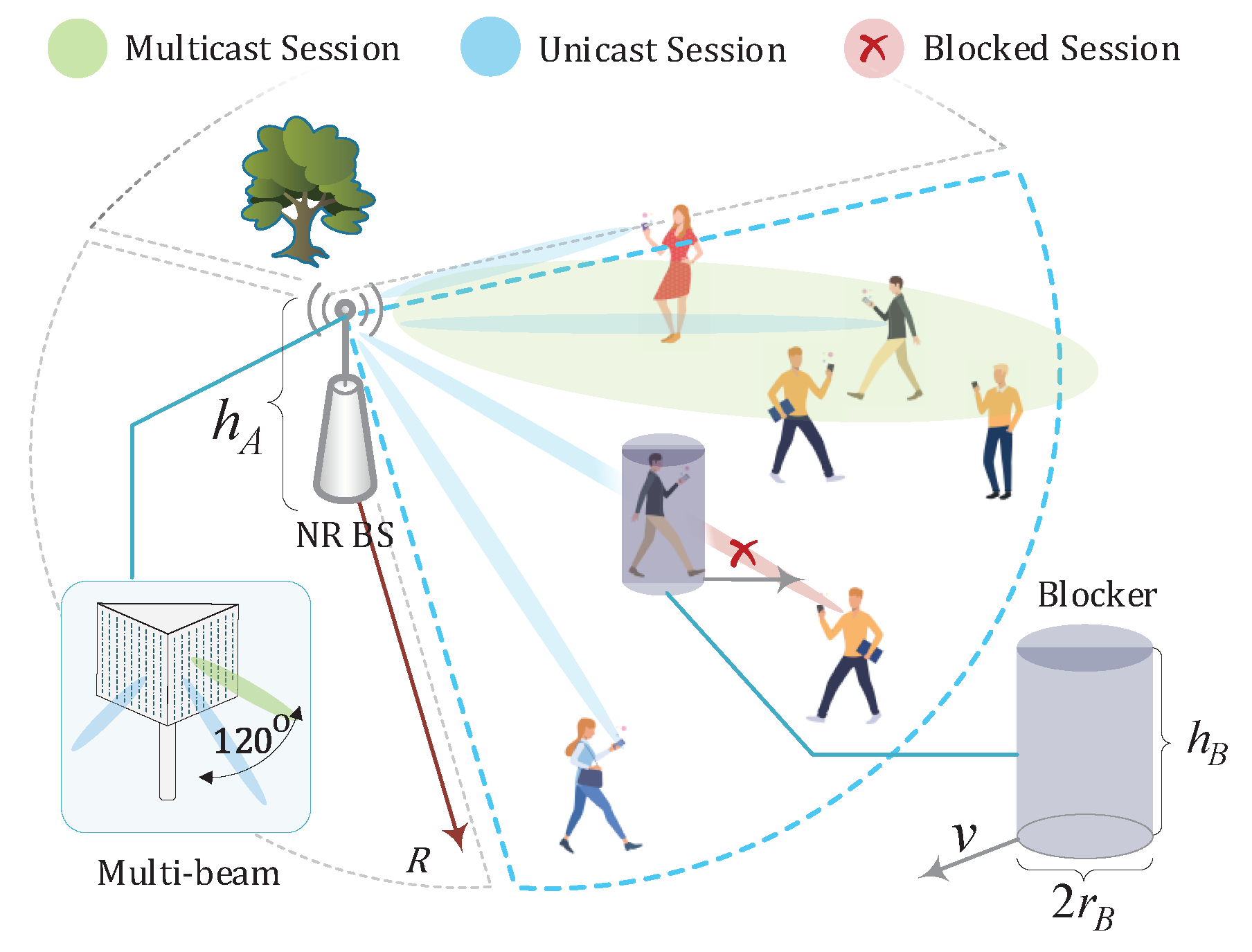
3.1. Deployment Model

We consider a cellular deployment of mmWave NR BS as shown in Figure 1. The coverage area of each BS is approximated by a circularly-shaped area of radius R estimated using the mmWave propagation model and the set of MCS [14]. Each site is associated with three antennas each covering the sector with the angle of 120 . The height of mmWave NR BS is fixed and set to h A . The operational frequency is f c . Each mmWave NR BS antenna is assumed to operate over B resource blocks. Recall, that the bandwidth of the resource block is affected by the utilized NR numerology. In our study, we use numerology 3.
We consider a field of humans forming a Poisson point process (PPP) with density λ B blocking the propagation paths. Blockers are modeled by cylinders with the fixed height and width, h B and r B , respectively. The height of UE is h U , h U < h B .

3.2. Propagation and Antenna Models

The value of SNR at the UE can be written as
S ( x ) = P T G A G U x ζ T e K x N 0 + M T ,
where ζ T is path loss exponents in LoS non-blocked state, M T is the constant capturing interference and shadow fading on LoS non-blocked state, N 0 is density of noise, P T is emitted power, G A and G U are the BS and UE gains.
To define the path loss, L ( y ) , for mmWave systems one utilize the urban-micro (UMi) providing path loss in the following form
L d B ( y ) = 32.4 + 21 log 10 y + 20 log 10 f c , non-bl . , 32.4 + 31.9 log 10 y + 20 log 10 f c , blocked ,
where f c is the carrier measured in GHz.
The path loss defined in (1) can also be converted to the linear scale by utilizing the generic representation A i y ζ i , where A i , ζ i , i = 1 , 2 , are the propagation coefficients corresponding to LoS non-blocked ( i = 1 ) and blocked ( i = 2 ) conditions, i.e,
A = A 1 = A 2 = 10 2 log 10 f c + 3.24 , ζ 1 = 2.1 , ζ 2 = 3.19 .

3.3. Antenna Model

We assume planar antenna arrays at both the BS and the UE. Similarly to [15,16], we utilize the cone model with the beamwidths corresponding to the HPBW of the antenna radiation pattern. The BS transmit and UE receive antenna gains are denoted by G A and G U , respectively. Using [17] the mean antenna gain over HPBW is calculated as
G = 1 θ 3 d b + θ 3 d b θ 3 d b θ 3 d b + sin ( N · π cos ( θ ) / 2 ) sin ( π cos ( θ ) / 2 ) d θ ,
where N · is the number of antenna elements at the side of interest.
The HPBW of the array, α , can be determined as α = 2 | θ m θ 3 d b ± | , where θ m is the array maximum that can be computed as θ m = arccos ( 1 / π ) , θ 3 d b ± are the upper and lower 3-dB points estimated as θ 3 d b ± = arccos [ ± 2.782 / ( J π ) ] . For practical calculations we employ HPBW approximation given by 102 / N · , where N · is the number of antenna arrays in the appropriate plane [17,18]. Similarly, the linear gain can be approximated by the number of elements [17].
Note that in practice, the antenna parameters may drastically deviate from the theoretically predicted one as they heavily depend on the utilized technology. The research of the antenna system for 5G mmWave NR has been fairly productive so far. Particularly, the use of metamaterials for constructing efficient antennas is considered in [19,20]. Microstrip antennas have been proposed in [21,22]. The on-chip implementation with an extension of the application to terahertz band is considered in [23]. However, the approach proposed in the rest of the paper can be applied to any antenna as long as HPBW and gains can be explicitly calculated.

3.4. Service and Traffic Models

We consider a multi-layer NR service with four layers, one base layer, and three enhancement ones. The rate of the base layer is d M . Each user is assumed to be subscribed to the base layer. All the users also want to receive enhancement layers which are associated with the rate d U , l , l = 1 , 2 , 3 . The intensity of user requests for service is assumed to be Poisson with parameter Λ = λ δ π R 2 , where λ is the parameter of exponentially distributed intervals between two consecutive requests and δ is the density of users. Recalling the PPP assumption of the human distribution in 2 , the geometric location of a new session request is distributed uniformly within the coverage area of a BS [24]. Utilizing this observation, one may estimate the amount of resource required for base and enhancement layers as shown in, e.g., [25,26]. The VR session holding times are assumed to be exponentially distributed with the parameter μ .
Upon arrival of a new session from the UE located in the area with no multicast service provisioned, a multicast session is initiated and the user is always allocated a base layer. Otherwise, if the new session is established in the area that is already covered by multicasting service, it joins the corresponding multicast group and proceeds without additional resources. Then, if there is a sufficient amount of resources available at BS, it allows a user to be also provided with the enhancement layers. However, if the amount of resources is insufficient the enhancement layer is dropped.

3.5. Metrics of Interest

For the described system model we first interested in the enhancement layer provisioning probability, p i , i = 1 , 2 , 3 , as a function of BS deployment density. Once the task is solved we proceed to specify the algorithm allowing us to assess the required density of BS deployment.

4. Performance Evaluation

In this section, we develop our performance evaluation framework. We start developing a mathematically tractable user grouping algorithm for multicast service. Then, we formulate the problem of enhancement layer provisioning as a queuing system. Finally, we propose the algorithm for assessing the required BS density.

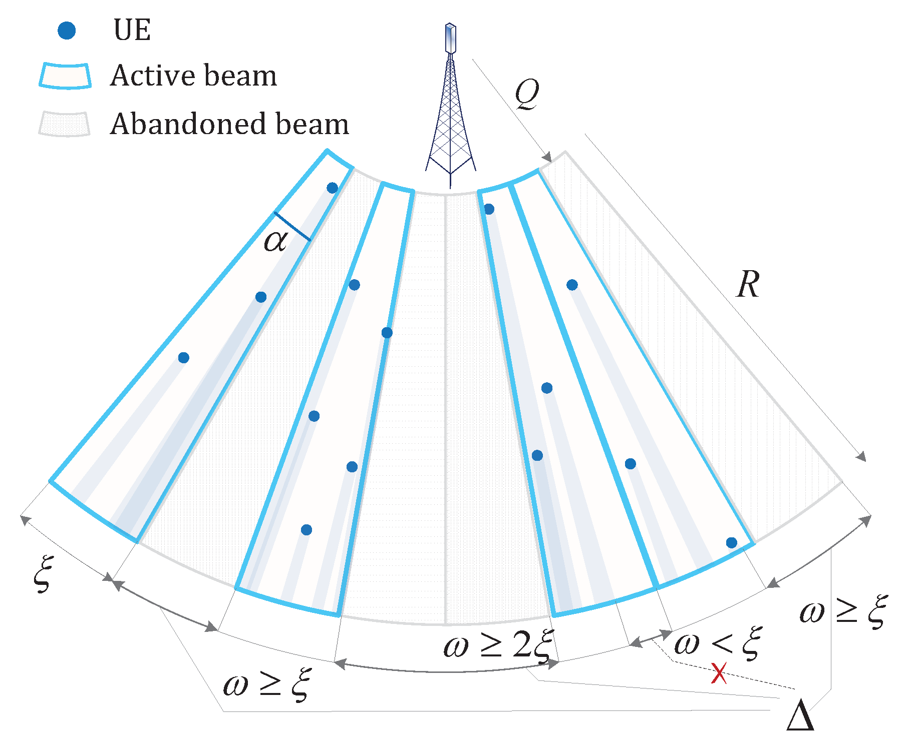
4.1. Multicast Group Formation

We propose to form multicast groups according to the maximum HPBW angle α for a given coverage radius R. To evaluate α , we first define the appropriate antenna gain as
G A = S R N 0 + M T P A G U R ζ T e K R p B R .
Then, once we obtain G A , we can easily define the HPBW value for specified antenna parameters the way it is presented in Table 2. Here we denote α G A as HPBW angle corresponding to the next nearest predefined value of G A .
Now, we can establish the number of multicast groups N as
N = Θ 120 α G A α G A ,
where Θ is the arc segment of the BS antenna. To employ Hellman’s model, we convert the HPBW angle to the length of the corresponding arc segment circumference
ξ = α G A π R 180 ,
as shown in Figure 2.
Following [27], the gaps between two neighbor shadows follow exponential distribution with parameter λ K 2 2 R , allowing us to find the probability q k that a gap ω is confined between k and k + 1 segments as
q k = e λ K 2 k ξ 2 R e λ K 2 ( k + 1 ) ξ 2 R ,
and can eventually not be covered by beams. This allows us to estimate the mean number of void beams Δ as
Δ = π λ K 2 3 e λ B R Q + λ k = 1 N k q k .
Finally, the mean number of required beams is calculated as N Δ .
The demand for resource of a single beam depends on whether all the covered UEs are in LoS conditions, or there at least one UE is blocked and requires the whole group to lower its MCS [28]. Thus, to estimate the mean resource required by an active beam, we first calculate the probability of having u UEs covered by the beam that follows Poisson distribution in accordance with the PPP as
q u = e λ n λ n u u ! ,
where λ n = λ π ( R 2 Q 2 ) ( α / 360 ) .
Eventually, the mean demand for an active beam is calculated as
b M = u = 1 q u b M , L i = 1 u 1 p B , i + ( 1 i = 1 u 1 p B , i ) b M , B ,
where b M , L and b M , B are the demands for resource blocks in LoS non-blocked and LoS blocked conditions respectively, while p B , i is the LoS blockage probability of the UE that is i-s closest to the NR BS.
Following [25], LoS blockage probability depends on both intensity of blockers entering the blockage zone, i.e.,
μ B , i = 0 f i x x h B h U + r B h T h U ( 2 r B λ B v ) 1 h T h U d x .
where h A , h U , and h B are the heights of NR BS, UE, and blockers respectively, r B and v are the radius and speed of blockers; and the distance between a UE and NR BS that follows the pdf of the distance to the i-s nearest neighbor in PPP [24]
f i ( x ) = 2 ( π λ ) i ( i 1 ) ! x 2 i 1 e π λ x 2 , x > 0 , i = 1 ,
Then, LoS blockage probability of the UE can be found as
p B , i = μ B , i μ B , i + v 2 r B ,
where 2 r B / v is the mean time for a blocker to cross the LoS blockage zone at right angle to its long side.
Another grouping approach based on multi-session multicasting is presented in [29]. A grouping algorithm allows to achieve better spectral efficiency and obtain an optimal resource allocation using convex optimization. The proposed incremental multicast grouping (IMG) scheme provides the opportunity to create sessions with many tiles of different quality, therefore, the number of sessions is equal to the number of user groups. However, at the same time, as users can request several multicast sessions, so the number of multicast sessions and multicast groups can be different. The work [30] presents an optimization algorithm for combinatorial clustering, in which multicast groups are divided into smaller subgroups, and subcarriers are allocated to each subgroup. The authors propose a new multicast grouping scheme based on generalized gradient approximation (GGA) and a genetic grouping algorithm to maximize the aggregate data rate. GGA is an evolutionary clustering technique in which the corresponding structures of the clustering problem are encoded as genes on the chromosomes. An initial group of chromosomes is first created by matching the multicast clustering solution to the chromosome structure. And then, according to the fitness values, all chromosomes are ranked from best to worst, and they are assigned the probability of selection based on the normalized geometric distribution.

4.2. Enhancement Layer Service

To evaluate the mean amount of resources required to deliver the additional layers of video via unicast service, we first estimate the resource amount needed to deliver each of the L layers to the specified share of users. We model the delivering process of a layer as M / M / C queuing system [31], where λ is the intensity of requests for the layer delivery, μ 1 is the mean duration of the requested video fragment that is supposed to follow exponential distribution, and C is the number of active unicast sessions that should be maintained to fulfill the specified probability of successful delivery. The drop probability, p C = E C ρ , for the queue can be found by utilizing the celebrated Erlang-B expression
E C ( ρ ) = ρ C / C ! m = 0 C ( ρ m / m ! ) , 0 ρ < .
To avoid computational complexity we use the recursive algorithm for calculating the M / M / C steady-state distribution [32], i.e.,
I 0 ρ = 1 , I v ρ = 1 + ρ v I v 1 ρ , v = 1 , 2 ,
where I v ρ = E v ρ 1 .
Finally, we evaluate the mean demand for delivery of l-s enhancement layer as
E l U = C l p B , i b U l , B + 1 p B , i b U l , L ,
where b U l , B and b U l , L are the demands for a single UE to download the l-s layer in LoS blocked and non-blocked conditions.

4.3. Deployment Density Assessment

Having solved the direct problem, we now proceed developing the algorithm for estimating the required mmWave NR BS deployment density satisfying a given enhancement layer drop probabilities, p U .
The proposed algorithm is presented in the form of pseudo-code in Algorithm 1. According to it, at step 1 we start with the maximum possible cell radius R = d E . Then, we define the appropriate antenna gain G A to form beams (step 2) that allow serving an active session at the distance R even in LoS blocked conditions. Once we have the HPBW angle, we obtain the number of beams N needed to provide full coverage of the cell’s sector at step 3. Note that some of the beams may not be effective, as they do not cover any users. To abandon the void beams, at step 4 we estimate the number of gaps between shadows, Δ , that are greater than the beamwidth as in (2). Afterward, we subtract these gaps from the number of beams to retain only “active” ones and calculate the amount of the required resource (step 5) for the base layer.
Then, at steps 6–20, we estimate the amount of resources for the enhancement layers using Erlang-B formula. We first start with one server in the M / M / C queuing system and check whether it is enough to meet the QoS profile requirement defined by 8, i.e., whether the loss probability p C ( l ) is lower than the share of users without successful layer delivery. If the condition is not satisfied, we increment the number of servers C l (step 9) and perform the calculations again till the appropriate number of servers is found. Once C l is obtained, it is treated as the mean number of active unicast sessions needed to deliver l-s layer to users, allowing us to estimate the total resource demand for l-s layer at step 19.
Finally, if the calculated demands for all the layers fit into the given bandwidth (step 21), we conclude that the coverage radius and corresponding density (step 25) of BSs are optimal. However, if the demands are greater than the given resource, we reduce the coverage radius (step 22) and perform the algorithm once again.
Algorithm 1 NR BS Deployment Density Assessment
Input: d E , λ , μ , p U , b , Q, p B , i
Output: λ A
Initialization:
1:
R = d E , ρ = λ / μ , K = R 2 Q 2
Assessment of resource amount for base layer:
2:
G A = S 1 R N 0 W A P A G U R ζ p B R
3:
ξ = α G A π R 360 , N = 120 120 α G A α G A
4:
Δ = π λ K 2 3 e λ B ¯ R Q + λ · k = 1 N e λ K 2 k ξ 2 R e λ K 2 ( k + 1 ) ξ 2 R
5:
E W = b M N Δ
Assessment of resource amount for enhancement layers:
6:
for l = 2 to L do
7:
      C l = 0 , p C ( l ) = 1
8:
      while   p C ( l ) > 1 p U ( l ) do
9:
            C l = C l + 1
10:
          p 0 ( l ) = 1
11:
        for   υ = 1 to C l do
12:
      p υ ( l ) = ρ · p υ 1 ( l ) υ + ρ · p υ 1 ( l )
13:
  end for
14:
          G = υ = 0 C p υ ( l )
15:
        for   υ = 1 to C do
16:
      p υ ( l ) = p υ ( l ) G
17:
   end for
18:
   end while
19:
      E l U = C l p B , i b U l , B + 1 p B , i b U l , L
20:
end for
Stop criteria:
21:
if l = 2 L E l U + E W > B then
22:
      R = R 1
23:
   return to Step 6
24:
else
25:
      λ A = π R 2 1
26:
   return λ A
27:
end if

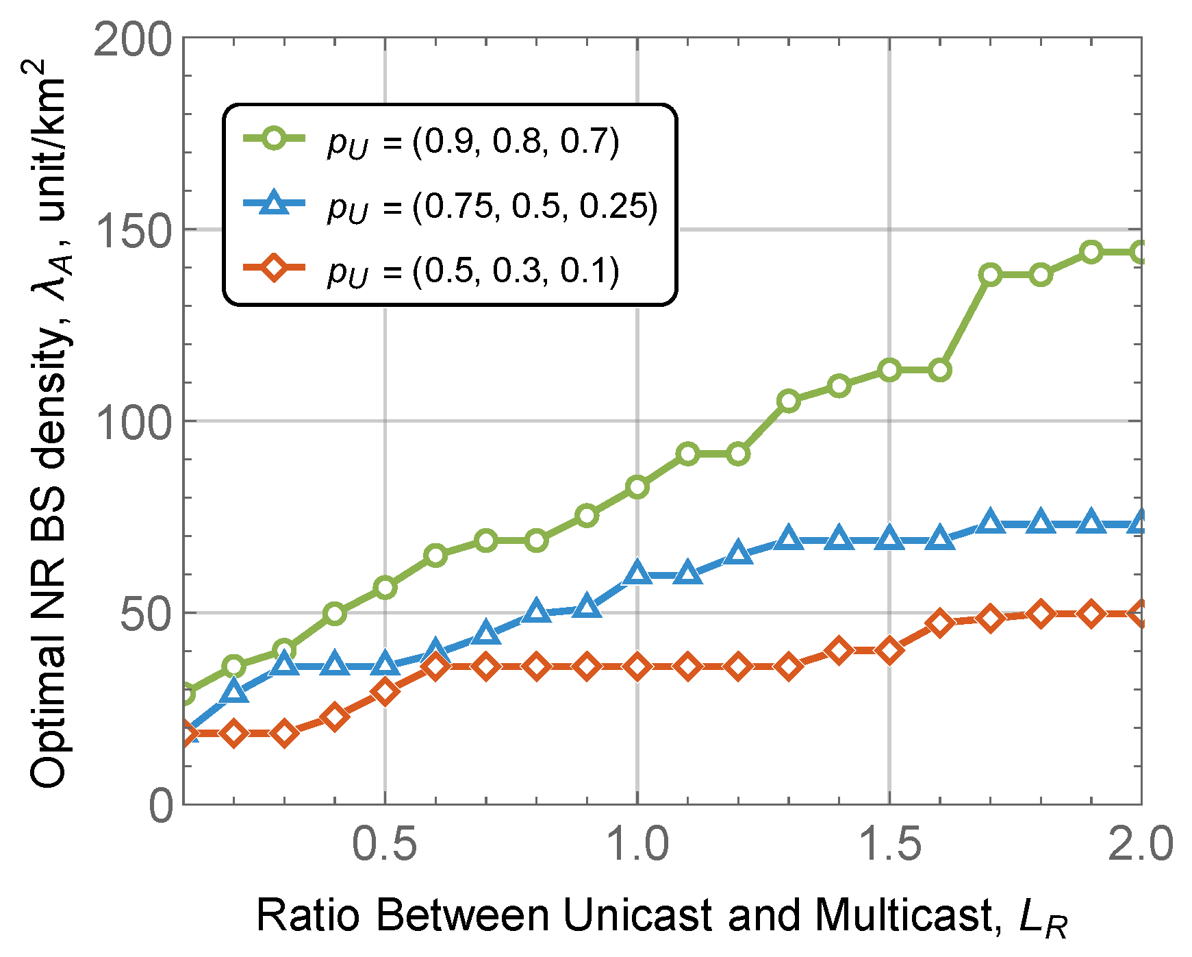
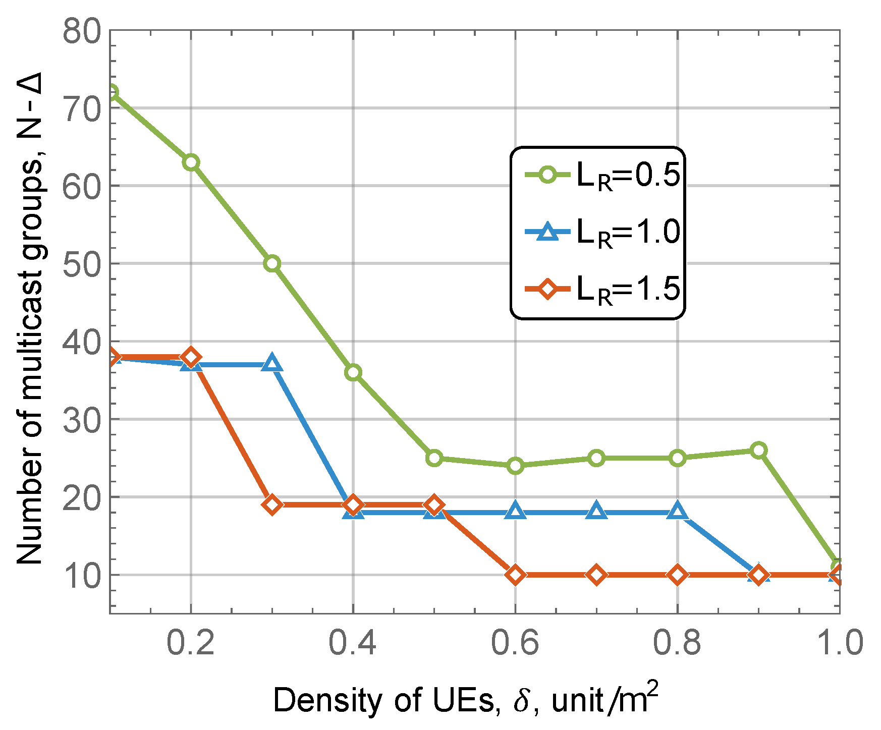
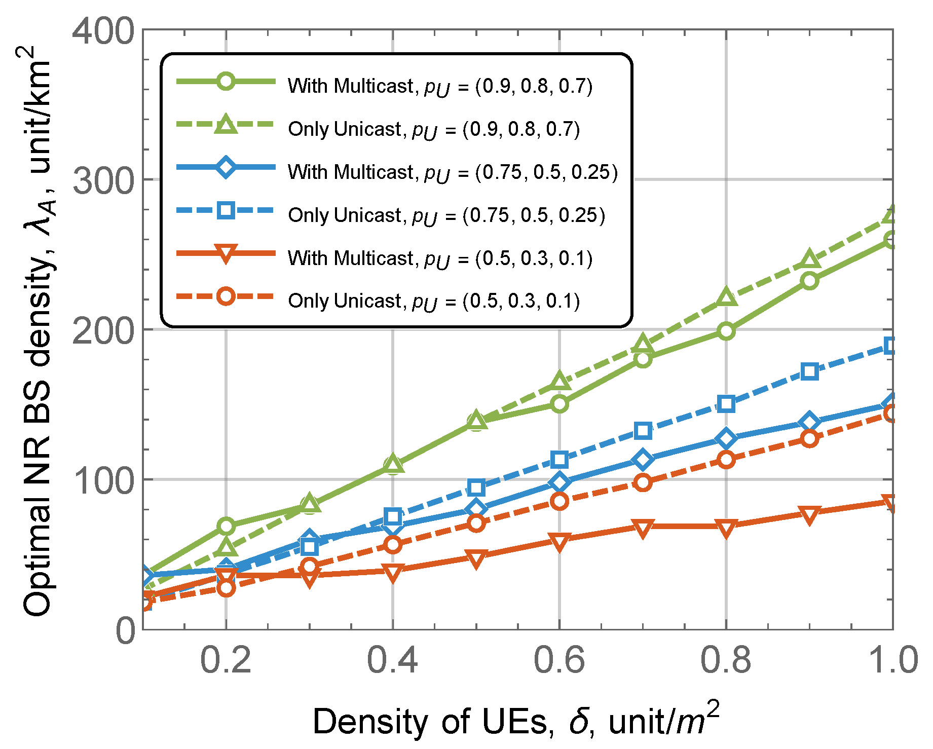
5. Numerical Results

In this section, we numerically elaborate on the proposed multi-layer VR delivery scheme. To this aim, we first compare the proposed multicast grouping scheme with the ones reported in the literature. Then, by utilizing the density of NR BS deployment as the main metric of interest, we report our main performance evaluation results. The antenna parameters utilized in our calculations are provided in Table 2. The default system parameters utilized in this section are shown in Table 3.

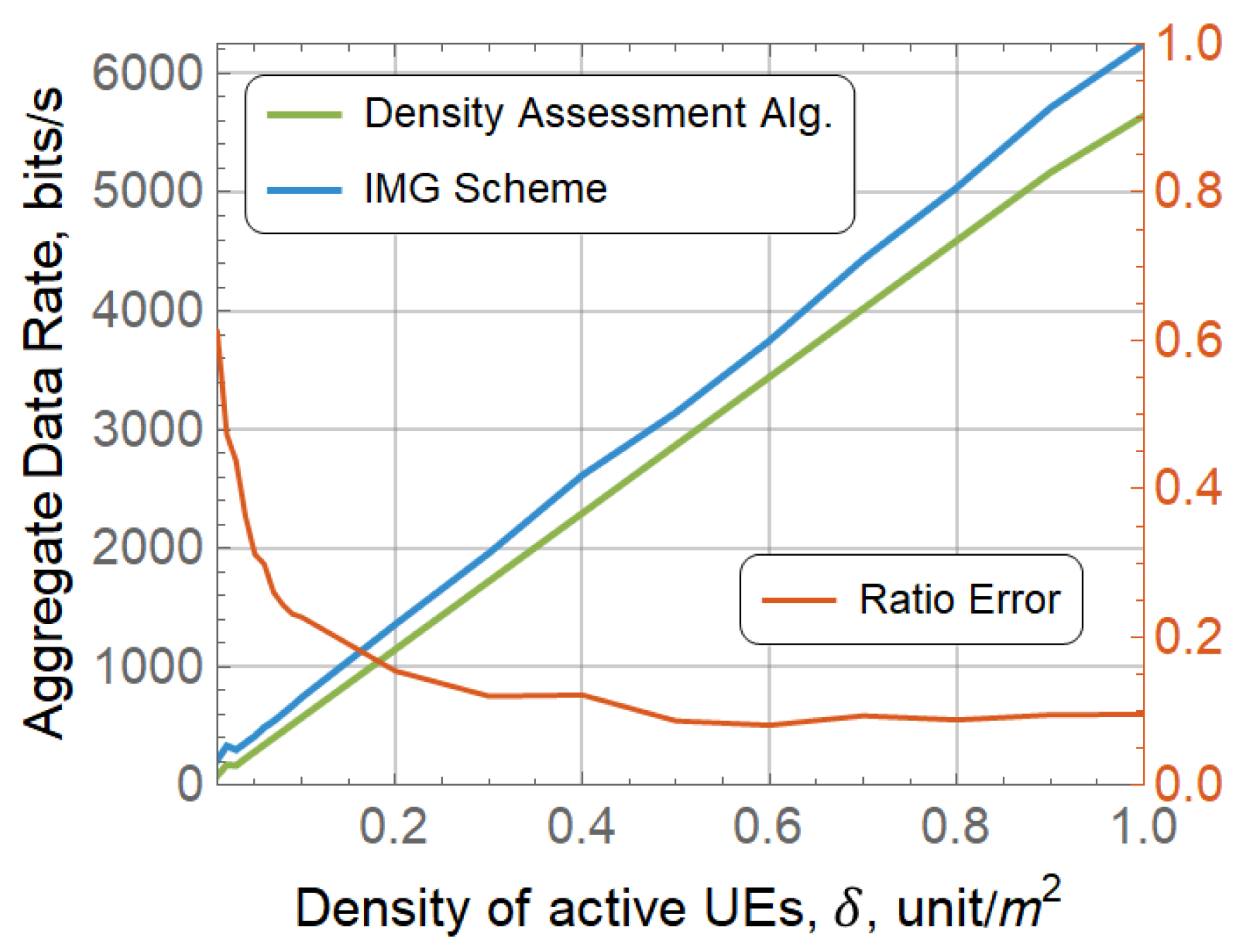
5.1. Comparison with Other Grouping Schemes

We start by comparing the average data rate (ADR) parameter for the proposed scheme and the one reported by Park et al. in [29], so-called IMG scheme. To this aim, in Figure 3 both schemes are compared using the same default setup from from Table 2 and Table 3. Here, we first define optimal radius with our algorithm and then put it to the IMG scheme for subgrouping. Once we obtain this subgrouping, we calculate and compare ADR for multicast service only. Recall, that Park et al. [29] utilizes an increment of 10 degrees for HPBW at each iteration.
By analyzing the presented data, one may observe that IMG scheme utilizes the widest beams with the longest coverage distance in approximately 50–70% of cases when UE density is λ 0.3 . Similar numbers are observed for our algorithm. In fact, the two considered grouping schemes converge in dense conditions. Recall, that, at the same time, the proposed scheme is much simpler in terms of implementation as the number of groups can be directly computed. Thus, in what follows, we utilize the proposed scheme to present the performance evaluation results for multi-layer VR service.

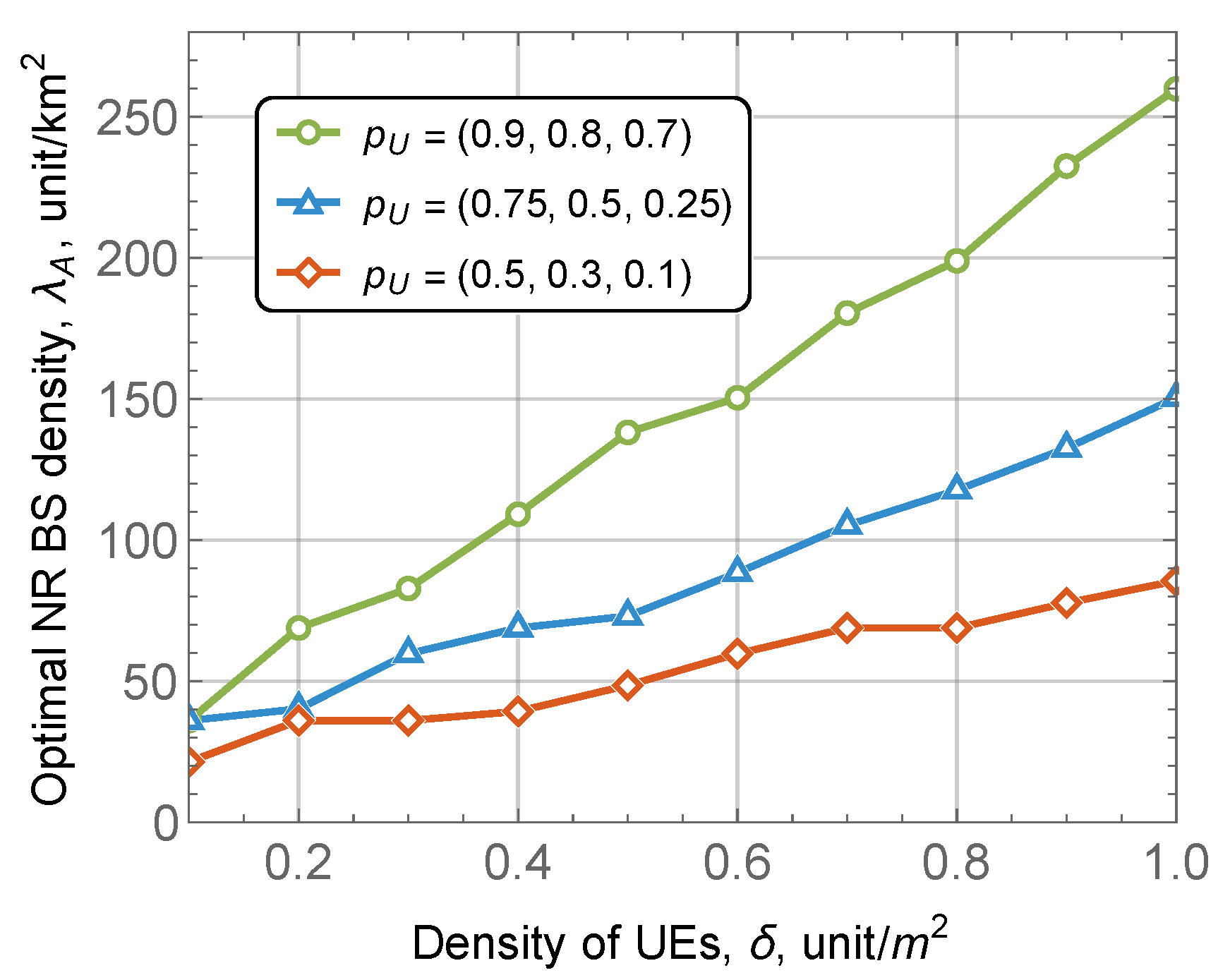
5.2. Performance Assessment

Having observed the performance of the proposed grouping algorithm we now proceed to assess multi-layer VR service performance. We start with Figure 4 showing the optimal BS deployment density as a function of UE density for 3 QoS profiles defined by p U and λ B is set to 0.3 . Recall that QoS profiles p U specifies the share of users that should receive l-th layer of quality enhancement. That is, the profile ( 0.5 , 0.3 , 0.1 ) impose mild data rate requirements than the one with ( 0.75 , 0.5 , 0.25 ) . The latter, in its turn, is characterized by smaller data rate requirements than the one with ( 0.9 , 0.8 , 0.7 ) .
By analyzing the data presented in Figure 4 one may observe that the scheme with ( 0.5 , 0.3 , 0.1 ) is logically characterized with the least required NR BS density. On top of this, this QoS profile is also associated with the lowest increase in terms of the required NR BS density. Particularly, for the density of approximately 0.2 UE/m2 and 1.0 UE/m2 the associated NR BS densities are just 25 BS/km2 and 90 BS/km2, respectively. The latter values are as large as 150 and 250 for ( 0.75 , 0.5 , 0.25 ) and ( 0.9 , 0.8 , 0.7 ) QoS profiles, respectively. Also, logically, the stricter the QoS profile the higher the required BS density. The latter trend holds for all considered ranges of UE densities.
A critical parameter affecting the performance of mmWave system is the blockers’ density. To assess its effect on the performance of the proposed scheme for QoS-aware multi-layer VR distribution service we show the optimal NR BS deployment density as a function of λ B in Figure 5, where the UE density is set to 0.3 . Here, we observe clearly non-linear trends. More specifically, both ( 0.5 , 0.3 , 0.1 ) and ( 0.75 , 0.5 , 0.25 ) QoS profiles are only mildly affected by the blockers’ density across the whole considered range. However, ( 0.9 , 0.8 , 0.7 ) QoS profile leads to the larger increase in the amount of required NR BS reaching 110 BS/km2 for λ B = 1.0 bl./m2. Note that the corresponding NR BS densities for ( 0.5 , 0.3 , 0.1 ) and ( 0.75 , 0.5 , 0.25 ) QoS profiles are just 60 BS/km2 and 40 BS/km2 respectively.
One of the critical advantages of the considered multi-layer VR service is that it allows implementing the basic layer by multicast service, thus, decreasing the demands to the rate at the air interface. To assess the efficiency of utilizing the multicast for delivering the base layer of the considered multi-layer VR service, we introduce the coefficient L R specified as the ratio of unicast layers to the basic layer. In other words, demands of unicast layers are multiplied by coefficient L R resulting in varying unicast traffic load. The results are illustrated in Figure 6 shows the required density of NR BSs as a function of the ratio between unicast and multicast layers, L R , for UE and blockers density set to 0.3 UE/m2 and 0.3 bl./m2, respectively.
Analyzing the results presented in Figure 6 one may observe that the density of NR BSs logically increases with the increase the ratio of unicast to multicast traffic, L R , required to provision the service. Here, the gap between different QoS profiles also increases with the increase in L R coefficient. The rationale is that user-specific unicast sessions enhancing quality for users start to take occupy a significant share of resources.
Note that the ratio between unicast and multicast traffic also affects the choice of the groups utilized for service provisioning. This trend is shown in Figure 7 as a function of UE density for blockers density set to 0.3 bl./m2. Here, one may observe that there is significant difference between very strict QoS profile ( 0.9 , 0.8 , 0.7 ) and milder ones, ( 0.75 , 0.5 , 0.25 ) and ( 0.5 , 0.3 , 0.1 ) . Note that the gap is highest for smaller values of UE density reaching 30–40 groups and decreases and UE densities grow. The rationale is that for high UE density the whole sectors served by NR NB antenna need to be covered. For sparse UE deployment, this is not the case leading to the noticeable difference in the number of utilized groups.
To complement the analysis above, we also compare the proposed scheme utilizing multicast transmissions for distributing the basic layer with the one relying upon the unicast service only. The results of this comparison are shown in Figure 8 as a function of UE density for blockers density set to 0.3 bl./m2. By analyzing these data, one may observe that at low UE densities multicast service for distributing the basic layer is ineffective. The highest gain is observed when the demand for the base layer is much higher than for enhancement ones.

6. Conclusions

In this paper, we proposed and evaluated the performance of a multi-layer VR distribution service that utilizes both multicast and unicast transmissions to deliver the service to the users. Our numerical results indicate that the proposed grouping scheme providing closed-form expressions for the number of groups and their configurations is characterized by similar performance as iterative algorithms provided in the literature. At low UE densities, the use of multicast service for distributing the basic layer is ineffective. The highest gains are observed when the demand for the base layer is much higher than for enhancement ones. QoS profile, as well as UE density, have a profound impact on the required density of NR BS. At the same time, the effect of blockers density is non-linear having the greatest impact on strict QoS profiles. In general, depending on the parameters the required density of NR BSs may vary in the range of 20–250 BS/km2.
The presented study provides a simple and efficient algorithm to evaluate the density of NR BSs required to support a given density of multi-layer VR UEs with prescribed QoS guarantees. One of the potential extensions of the study is related to considering the 5G NR deployments serving a mixture of unicast and multicast traffic.

Author Contributions

Conceptualization, D.M. and Y.G.; methodology, D.M.; software, V.B.; validation, D.M. and Y.G.; formal analysis, V.B. and D.O.; investigation, V.B., R.K. and E.G.; writing—original draft preparation, D.M., V.B. and D.O.; writing—review and editing, D.M., A.C. and D.O.; visualization, R.K. and E.G.; supervision, D.M. and Y.G.; funding acquisition, Y.G. and A.C. All authors have read and agreed to the published version of the manuscript.

Funding

This paper has been supported by the RUDN University Strategic Academic Leadership Program (recipient Alexander Chursin). The reported study has been funded by RFBR, projects 19-07-00933, 20-07-01064.

Institutional Review Board Statement

Not applicable.

Informed Consent Statement

Not applicable.

Data Availability Statement

The data presented in this study are available on request from the corresponding author.

Conflicts of Interest

The authors declare no conflict of interest.

Abbreviations

The following abbreviations are used in this manuscript:
3DThree-dimensional
3GPP3rd Generation Partnership Project
BSBase station
FoVField of view
GGAGeneralized gradient approximation
HPBWHalf-power bandwidth
IMGIncremental multicast grouping
LoSLine-of-sight
LTELong term Evolution
MCSModulation and coding scheme
MIMOMultiple input multiple output
mmWaveMillimeter wave
NRNew Radio
PPPPoisson point process
QoEQuality of experience
QoSQuality of service
SNRSignal to noise ratio
SVCScalable video coding
UEUser equipment
UMiUrban-micro
VRVirtual reality

References

  1. Holma, H.; Toskala, A.; Nakamura, T. 5G Technology: 3GPP New Radio; John Wiley & Sons: New York, NY, USA, 2020. [Google Scholar]
  2. Lin, X.; Li, J.; Baldemair, R.; Cheng, J.F.T.; Parkvall, S.; Larsson, D.C.; Koorapaty, H.; Frenne, M.; Falahati, S.; Grovlen, A.; et al. 5G new radio: Unveiling the essentials of the next generation wireless access technology. IEEE Commun. Stand. Mag. 2019, 3, 30–37. [Google Scholar] [CrossRef] [Green Version]
  3. Le, T.K.; Salim, U.; Kaltenberger, F. An overview of physical layer design for Ultra-Reliable Low-Latency Communications in 3GPP Releases 15, 16, and 17. IEEE Access 2020, 9, 433–444. [Google Scholar] [CrossRef]
  4. Hoppari, M.; Uitto, M.; Mäkelä, J.; Harjula, I.; Rantala, S. Performance of the 5th Generation Indoor Wireless Technologies-Empirical Study. Future Internet 2021, 13, 180. [Google Scholar] [CrossRef]
  5. Samuylov, A.; Moltchanov, D.; Kovalchukov, R.; Pirmagomedov, R.; Gaidamaka, Y.; Andreev, S.; Koucheryavy, Y.; Samouylov, K. Characterizing Resource Allocation Trade-Offs in 5G NR Serving Multicast and Unicast Traffic. IEEE Trans. Wirel. Commun. 2020, 19, 3421–3434. [Google Scholar] [CrossRef]
  6. Karembai, A.K.; Thompson, J.; Seeling, P. Towards Prediction of Immersive Virtual Reality Image Quality of Experience and Quality of Service. Future Internet 2018, 10, 63. [Google Scholar] [CrossRef] [Green Version]
  7. Nasrabadi, A.T.; Mahzari, A.; Beshay, J.D.; Prakash, R. Adaptive 360-degree video streaming using layered video coding. In Proceedings of the 2017 IEEE Virtual Reality (VR), Los Angeles, CA, USA, 18–22 March 2017; pp. 347–348. [Google Scholar] [CrossRef]
  8. Long, K.; Cui, Y.; Ye, C.; Liu, Z. Optimal Transmission of Multi-Quality Tiled 360 VR Video by Exploiting Multicast Opportunities. In Proceedings of the 2019 IEEE Global Communications Conference (GLOBECOM), Waikoloa, HI, USA, 9–13 December 2019; pp. 1–6. [Google Scholar] [CrossRef] [Green Version]
  9. Park, J.; Hwang, J.; Wei, H. Cross-Layer Optimization for VR Video Multicast Systems. In Proceedings of the 2018 IEEE Global Communications Conference (GLOBECOM), Abu Dhabi, United Arab Emirates, 9–13 December 2018; pp. 206–212. [Google Scholar] [CrossRef]
  10. Perfecto, C.; Elbamby, M.S.; Ser, J.D.; Bennis, M. Taming the Latency in Multi-User VR 360°: A QoE-Aware Deep Learning-Aided Multicast Framework. IEEE Trans. Commun. 2020, 68, 2491–2508. [Google Scholar] [CrossRef] [Green Version]
  11. Hosseini, M.; Swaminathan, V. Adaptive 360 VR Video Streaming: Divide and Conquer. In Proceedings of the IEEE International Symposium on Multimedia (ISM), San Jose, CA, USA, 11–13 December 2016; pp. 1–4. [Google Scholar]
  12. Zuhra, S.u.; Chaporkar, P.; Karandikar, A. Toward Optimal Grouping and Resource Allocation for Multicast Streaming in LTE. IEEE Trans. Veh. Technol. 2019, 68, 12239–12255. [Google Scholar] [CrossRef]
  13. Tran, T.X.; Yue, G. GRAB: Joint Adaptive Grouping and Beamforming for Multi-Group Multicast with Massive MIMO Networks. In Proceedings of the IEEE Globecom Workshops (GC Wkshps), Waikoloa, HI, USA, 9–13 December 2019; pp. 1–6. [Google Scholar]
  14. 3GPP. Physical Channels and Modulation (Release 16). 3GPP TR 38.211 V16.5.0. Available online: https://www.3gpp.org/ftp/Specs/archive/38_series/38.211/38211-g50.zip (accessed on 25 May 2021).
  15. Petrov, V.; Komarov, M.; Moltchanov, D.; Jornet, J.M.; Koucheryavy, Y. Interference and SINR in Millimeter Wave and Terahertz Communication Systems With Blocking and Directional Antennas. IEEE Trans. Wirel. Commun. 2017, 16, 1791–1808. [Google Scholar] [CrossRef]
  16. Singh, S.; Mudumbai, R.; Madhow, U. Interference Analysis for Highly Directional 60-GHz Mesh Networks: The Case for Rethinking Medium Access Control. IEEE/ACM Trans. Netw. 2011, 19, 1513–1527. [Google Scholar] [CrossRef]
  17. Constantine, A.B. Antenna theory: Analysis and design. In Microstrip Antennas; John Wiley & Sons: New York, NY, USA, 2005. [Google Scholar]
  18. Gerasimenko, M.; Moltchanov, D.; Gapeyenko, M.; Andreev, S.; Koucheryavy, Y. Capacity of multiconnectivity mmWave systems with dynamic blockage and directional antennas. IEEE Trans. Veh. Technol. 2019, 68, 3534–3549. [Google Scholar] [CrossRef]
  19. Alibakhshikenari, M.; Virdee, B.S.; Azpilicueta, L.; Naser-Moghadasi, M.; Akinsolu, M.O.; See, C.H.; Liu, B.; Abd-Alhameed, R.A.; Falcone, F.; Huynen, I.; et al. A comprehensive survey of “metamaterial transmission-line based antennas: Design, challenges, and applications”. IEEE Access 2020, 8, 144778–144808. [Google Scholar] [CrossRef]
  20. Alibakhshikenari, M.; Babaeian, F.; Virdee, B.S.; Aïssa, S.; Azpilicueta, L.; See, C.H.; Althuwayb, A.A.; Huynen, I.; Abd-Alhameed, R.A.; Falcone, F.; et al. A comprehensive survey on “Various decoupling mechanisms with focus on metamaterial and metasurface principles applicable to SAR and MIMO antenna systems”. IEEE Access 2020, 8, 192965–193004. [Google Scholar] [CrossRef]
  21. Shirkolaei, M.M.; Jafari, M. A new class of wideband microstrip falcate patch antennas with reconfigurable capability at circular-polarization. Microw. Opt. Technol. Lett. 2020, 62, 3922–3927. [Google Scholar] [CrossRef]
  22. Mohammadi Shirkolaei, M. Wideband linear microstrip array antenna with high efficiency and low side lobe level. Int. J. RF Microw. Comput. Aided Eng. 2020, 30, e22412. [Google Scholar] [CrossRef]
  23. Althuwayb, A.A. On-chip antenna design using the concepts of metamaterial and SIW principles applicable to terahertz integrated circuits operating over 0.6–0.622 THz. Int. J. Antennas Propag. 2020, 2020, 6653095. [Google Scholar] [CrossRef]
  24. Moltchanov, D. Distance distributions in random networks. Ad Hoc Netw. 2012, 10, 1146–1166. [Google Scholar] [CrossRef]
  25. Begishev, V.; Moltchanov, D.; Sopin, E.; Samuylov, A.; Andreev, S.; Koucheryavy, Y.; Samouylov, K. Quantifying the impact of guard capacity on session continuity in 3GPP new radio systems. IEEE Trans. Veh. Technol. 2019, 68, 12345–12359. [Google Scholar] [CrossRef]
  26. Begishev, V.; Sopin, E.; Moltchanov, D.; Kovalchukov, R.; Samuylov, A.; Andreev, S.; Koucheryavy, Y.; Samouylov, K. Joint Use of Guard Capacity and Multiconnectivity for Improved Session Continuity in Millimeter-Wave 5G NR Systems. IEEE Trans. Veh. Technol. 2021, 70, 2657–2672. [Google Scholar] [CrossRef]
  27. Gapeyenko, M.; Samuylov, A.; Gerasimenko, M.; Moltchanov, D.; Singh, S.; Akdeniz, M.R.; Aryafar, E.; Himayat, N.; Andreev, S.; Koucheryavy, Y. On the temporal effects of mobile blockers in urban millimeter-wave cellular scenarios. IEEE Trans. Veh. Technol. 2017, 66, 10124–10138. [Google Scholar] [CrossRef] [Green Version]
  28. Samuylov, A.; Beschastnyi, V.; Moltchanov, D.; Ostrikova, D.; Gaidamaka, Y.; Shorgin, V. Modeling Coexistence of Unicast and Multicast Communications in 5G New Radio Systems. In Proceedings of the 2019 IEEE 30th Annual International Symposium on Personal, Indoor and Mobile Radio Communications (PIMRC), Istanbul, Turkey, 8–11 September 2019; pp. 1–6. [Google Scholar] [CrossRef]
  29. Park, H.; Park, S.; Song, T.; Pack, S. An incremental multicast grouping scheme for mmWave networks with directional antennas. IEEE Commun. Lett. 2013, 17, 616–619. [Google Scholar] [CrossRef]
  30. Tan, C.; Chuah, T.; Tan, S.; Sim, M. Efficient clustering scheme for OFDMA-based multicast wireless systems using grouping genetic algorithm. Electron. Lett. 2012, 48, 184–186. [Google Scholar] [CrossRef]
  31. Gorbunova, A.V.; Naumov, V.A.; Gaidamaka, Y.V.; Samouylov, K.E. Resource queuing systems as models of wireless communication systems. Inform. Primen. 2018, 12, 48–55. [Google Scholar]
  32. Khintchine, A.Y. Mathematical Methods in the Theory of Queueing; Griffin: London, UK, 1960. [Google Scholar]
Figure 1. System model.
Futureinternet 13 00185 g001
Figure 2. Illustration of the proposed multicast group formation procedure.
Futureinternet 13 00185 g002
Figure 3. ADR performance comparison.
Futureinternet 13 00185 g003
Figure 4. Optimal NR BS density as function of UE density.
Futureinternet 13 00185 g004
Figure 5. Optimal NR BS density as function of blocker density.
Futureinternet 13 00185 g005
Figure 6. Optimal NR BS density as function of QoS profile.
Futureinternet 13 00185 g006
Figure 7. Number of multicast groups as function of UE density.
Futureinternet 13 00185 g007
Figure 8. Comparison of multicast and unciast services for basic layer.
Futureinternet 13 00185 g008
Table 1. Notation utilized in the paper.
NotationDescription
f c operational frequency
Bnumber of available RBs
λ A density of NR BSs
λ B density of blockers
μ 1 mean UE passage time
r B blocker radius
h B blocker height
h U UE height
h A NR BS height
vUE speed
P A transmit power
G A BS antenna array gain
G U UE antenna array gain
ζ T path loss exponent in LoS non-blocked state
M T interference and shadow fading margin
α array HPBW
θ m array maximum
θ 3 d b ± upper and lower 3-dB points
Jnumber of antenna arrays
N U number of UE antenna array configurations
N T number of NR BS antenna array configurations
N 0 density of noise
Λ intensity of user requests
δ density of UEs
RNR BS cell radius
p B LoS blockage probability
ξ beam’s arc circumference
Δ number of void beams
Qminimum UE to NR BS distance
b M base layer demand
b U l l-s enhancement layer demand
C l mean number of sessions with l-s enhancement layer
p U QoS profile
Table 2. Antenna parameters utilized in calculations.
ArrayGain, dBiHPBW, o
64 × 417.581.59
32 × 414.583.18
16 × 411.576.37
8 × 48.5712.75
4 × 45.5725.50
Table 3. Default system parameters.
NotationDescriptionValues
f c operational frequency73 GHz
Bnumber of available RBs264
r B blocker radius0.4 m
h B blocker height1.7 m
h U UE height1.5 m
h A NR BS height4 m
vUE speed1.5 m/s
P T transmit power2 W
N U UE antenna array configurations64
N 0 density of noise−84 dBi
λ B density of blockers0.3 units/m2
ζ T path loss exponent2.1
λ intensity of video sessions from a UE 1 3600 sessions/s
μ mean session length15 s
d M base layer downloading rate 7.78 Mbps
d U enhancement layer downloading rates { 19.78 , 25.81 , 31.96 } Mbps
Qminimum UE to NR BS distance1 m
Publisher’s Note: MDPI stays neutral with regard to jurisdictional claims in published maps and institutional affiliations.

