Article

Computationally Efficient Energy Management in Hybrid Electric Vehicles Based on Approximate Pontryagin’s Minimum Principle

1
School of Mechanical and Precision Instrument Engineering, Xi’an University of Technology, Xi’an 710048, China
2
Department of Mechanical Engineering, Tarsus University, Tarsus, Mersin 33400, Turkey
*
Author to whom correspondence should be addressed.
World Electr. Veh. J. 2020, 11(4), 65; https://0-doi-org.brum.beds.ac.uk/10.3390/wevj11040065
Submission received: 8 September 2020 / Revised: 25 September 2020 / Accepted: 5 October 2020 / Published: 9 October 2020
(This article belongs to the Special Issue Power System and Energy Management of Hybrid Electric Vehicles)

Abstract

:
This article presents an energy management method for a parallel hybrid electric vehicle (HEV) based on approximate Pontryagin’s Minimum Principle (A-PMP). The A-PMP optimizes gearshift commands and torque distribution for overall energy efficiency. As a practical numerical solution in PMP, the proposed methodology utilizes a piecewise linear approximation of the engine fuel rate and state of charge (SOC) derivative by considering drivability and fuel economy simultaneously. Moreover, battery aging is explicitly studied by introducing a control-oriented model, which aims to investigate the effect of battery aging on the optimization performance in the development of the HEVs. An approximate energy management strategy with piecewise linear models is then formulated by the A-PMP, which targets a better performance for the Hamiltonian optimization. The gearshift map is extracted from the optimal results in the standard PMP to hinder frequent gearshift by considering both drivability and fuel economy. Utilizing an approximated Hamilton function, the torque distribution, gearshift command, and the battery aging degradation are jointly optimized under a unified framework. Simulations are performed for dynamic programming (DP), PMP, and A-PMP to validate the effectiveness of the proposed approach. The results indicate that the proposed methodology achieves a close fuel economy compared with the DP-based optimal solution. Moreover, it improves the computation efficiency by 50% and energy saving by 3.5%, compared with the PMP, while ensuring good drivability and fuel efficiency.

1. Introduction

1.1. Research Motivation

Environmental pollution and an energy crisis are pressuring the automotive industry to develop energy-efficient vehicle technology. From a technology perspective, the development of energy-efficient vehicles is one of the effective ways to realize a sustainable transportation system, therefore upgrading the automotive sector. As an energy-efficient vehicle, hybrid electric vehicles (HEVs) attract increasing attention in recent years due to excellent energy efficiency, smaller battery size, and longer range of mileage compared with battery electric vehicles [1]. The main challenge of devising HEVs depends on how to distribute the power among multiple power sources associated with the vehicular power demand. It is acknowledged that improvements in the fuel efficiency of HEVs as well as reduced emissions are highly dependent on their energy management strategies (EMSs) [2]. The EMS is one of the most popular topics for HEVs/Plug-in HEVs and has attracted more attention in the past decades. It is well known that the EMSs are generally realized as rule-based EMS and optimization-based EMSs. The rule-based EMSs can be implemented by predefining a set of logical rules according to HEV system characteristics and operation mode [3]. Thus, the rule-based EMSs are widely employed in the commercial application of vehicle controllers. However, the benefits from the rule-based EMSs are quite limited and generally sub-optimal, resulting in limited energy-savings. To this end, great efforts have been made in the field of optimization-based EMSs that can theoretically guarantee optimality. Among many methods, Pontryagin’s minimum principle (PMP), which is derived from dynamic programming (DP) through a variational approach, transforms the global optimization problem into an instantaneous Hamiltonian optimization problem. The optimal solution of traditional PMP is obtained by an interpolation method, while approximated models/simplified models is utilized for approximate PMP. Taking advantage of this fact, we aim to develop an optimal energy management strategy based on the approximate-PMP solution for parallel HEVs.

1.2. Literature Review

Pontryagin’s Minimum Principle offers necessary condition of co-state and system state for optimization of energy management in hybrid electric vehicles. As a representative global optimization approach, dynamic programming and Pontryagin’s minimum principle are usually employed to develop EMSs for HEVs. As a benchmark, DP is a numerical method for solving multistage decision-making problems [4]. It can obtain globally optimal results [5]; however, it cannot be directly applied to vehicles in practice due to the need of prior knowledge of an entire driving cycle (speed, road slope, etc.) as well as high computational burden. In the literature, Guzzella et al. [6] put forward DP-based energy management strategy for parallel hybrid electric vehicles. DP is firstly developed to devise an optimal gear shift strategy in [7]. Faras et al. [8] utilized a weighted improved DP to optimize the power allocation for the fuel cell hybrid electric vehicles. To improve the computation efficiency, Yang et al. [9] presented a fast DP approach for a power-split hybrid vehicle, which jointly optimizes the power split and the component parameter. Harselaar et al. [10] proposed two methods to enhance the implementation of DP by reducing the number of grid points. Modified DP with a velocity prediction is also presented in [11,12] to optimize the power split.
As stated, PMP, which is an analytical optimization approach derived from a DP-based global optimization problem, presents some advantages. For example, the form of instantaneous optimization in PMP makes real-time control possible. PMP-based EMS is proposed by minimizing the Hamiltonian function at each instant to optimize the power distribution in [13]. PMP provides necessary conditions for locally optimal trajectories in [14], which can be adopted to find optimal control candidates. Kim et al. [15] presented a PMP-based energy management strategy considering battery efficiency for PHEVs and derived an additional condition for the inequality state constraints. Using instantaneous driving conditions, an adaptive PMP for extended-range electric vehicles is investigated in [16]. Li et al. [17] proposed an adaptive EMS based on PMP for a fuel cell/battery hybrid vehicle to estimate the co-state with the predicted traffic information. Xie et al. [18] employed PMP to solve the model predictive control problem over a prediction horizon. Masood et al. [19] optimized the power split with PMP for multiple automated power-split HEVs with flexible power demand. In real conditions, the driving cycle is influenced by numerous factors (e.g., driver behaviors and traffic conditions). Thus, to improve the adaptability of PMP, Park et al. [20] investigated a PMP-based energy management strategy for plug-in HEV by considering the driver’s characteristics. The PMP utilized in fuel cell hybrid vehicles is also developed in [21,22].
Most of the works in the literature focus on the interpolation method for implementing PMP that may be computationally demanding. Although PMP transforms the global optimization problem into a local optimization, the challenge of optimizing the Hamiltonian still remains, particularly for a parallel HEV with automated mechanical transmission (AMT). The parallel HEVs with AMT are very popular in the HEV market, especially for commercial heavy-duty vehicles such as trucks. These vehicles need to fulfill the increasing requirements for fuel economy, emissions, and purchase cost. Their energy management cannot solely be specified by the optimal torque distribution but needs to be designed by taking into account the gearshift command. Due to the clutch on/off and discrete gearshift, the optimal solution cannot be directly obtained since it requires a derivative of the objective function. To solve this problem, numerical PMP [23] is usually employed using discrete models (e.g., engine and motor models with interpolation method), in which gearshift and torque split are considered as control input. This method may lead to the interpolation error and deterioration in the optimization in terms of accuracy of the result. Ritzmann et al. [24] optimized the torque split and gear selection based on a mixed-integer convex problem and a non-smooth PMP to improve the computation efficiency; however, frequent gear switching is not properly penalized. Steinbuch et al. [25] utilized a numerical PMP to optimize the gearshift command by directly adding a penalty function. Murgovski et al. [26] optimized the battery size for Plug-in HEVs by approximating the power limits using convex/concave functions in kinetic energy. Ambuhl et al. [27] utilized a simplified model to derive an explicit optimal control policy based on PMP for hybrid electric powertrains. Zheng et al. [28] compared a numerical equivalent consumption minimization strategy (ECMS) and PMP for a fuel cell hybrid vehicle. Hou et al. [29] proposed an approximate PMP considering the engine on/off state for a plug-in HEV.
However, frequent gearshift is not well studied, which results in discomfort of drivability. From the aforementioned literature, it is very challenging to optimize gearshift command and torque distribution simultaneously due to the tradeoff between fuel economy and drivability.
It is noted that tremendous progress has been achieved in synthesizing EMSs with PMP for HEVs; however, two major issues still exist. The first one is the fuel consumption, which is mainly considered in PMP implementation without considering drivability and battery aging together using approximate engine fuel and motor models. Many related works have been reported on energy management for power-split HEVs without involving gearshift command for better drivability. Moreover, it is essential to include battery aging in energy management for improved battery lifetime. The second one is the heavy computation burden even though some numerical PMP approaches are adopted. The computational load restricts the real-time application of PMP, especially when integrating a discrete gearshift with continuous torque-split optimization.
In the light of these issues and missing research gap, as an alternative method, we develop an approximate energy management based on PMP by simultaneously taking into account drivability and computation efficiency for a parallel HEV. To this end, gearshift command and torque split are firstly optimized using PMP to extract a gearshift map. This can then be applied in the approximate PMP framework to hinder frequent gearshift. Afterward, the approximate PMP that utilizes piecewise linear models for a parallel HEV is investigated to enhance its computation efficiency while guaranteeing good drivability and fuel economy. A battery aging model is introduced to incorporate the battery aging degradation into fuel consumption optimization for the approximate PMP. We then optimize the torque distribution by introducing the extracted gearshift map and approximated models. Comparative studies are also performed with DP and PMP to validate the effectiveness of the proposed method. To the best of our knowledge, utilizing piecewise linear models of the engine fuel rate and state of charge (SOC) derivative to devise an EMS for parallel HEVs by incorporating fuel economy, drivability, and battery aging has not been well studied.

1.3. Main Contributions

The primary purpose of this paper is to come up with a computationally efficient energy management approach based on the A-PMP, which utilized linear models of the engine fuel rate and SOC derivative for a parallel HEV. In this method, the drivability, fuel economy and battery aging are considered simultaneously. The A-PMP with piecewise linear models is developed to optimize the fuel efficiency for powertrain control by solving the Hamiltonian optimization. The main contributions are summarized as follows:
(1) First, the gearshift map is obtained using PMP to hinder frequent gearshift by compromising fuel economy and drivability and employed in an approximate PMP for a parallel HEV for the first time. This is essential to the success of the real-time implementation of PMP.
(2) Second, an approximate PMP approach with piecewise linear models is developed to optimize the torque distribution with the extracted gearshift map. To evaluate the fuel-saving potential, the optimization problem is formulated for a parallel HEV in terms of drivability and fuel efficiency. The computation efficiency is also improved for powertrain control, yielding a potential for real-time control.
(3) A control-oriented battery aging model is introduced into the A-PMP to better integrate fuel economy and battery aging by considering battery life degradation in the fuel consumption minimization.
(4) Finally, the approximate PMP is evaluated by comparing its performance to the DP and PMP under china typical city cycle (CTCC) in terms of optimal performance and computation efficiency. The performance of A-PMP is also analyzed by considering battery aging degradation. China’s typical city condition is assessed to reveal the optimization performance of the approximate PMP.

1.4. Outline

The rest of this paper is organized as follows. The vehicle model for a parallel HEV is detailed in Section 2. Section 3 introduces the overall scheme of the proposed energy management approach based on approximate models. The principle of the approximate PMP approach by incorporating the drivability and the battery cycle aging model is reformulated via an optimization problem. In Section 4, numerous simulation results are presented and discussed. Section 5 concludes this paper.

2. Powertrain Modelling

2.1. Powertrain Configuration

A single-shaft parallel hybrid electric vehicle (HEV) is utilized in this study, and its configuration is presented in Figure 1. The simplified structure makes it more popular in the HEV markets. With a clutch, several operation modes can be offered, such as motor-only, engine-only, hybrid driving, regenerative braking, and recharging modes. A motor is located between an automated mechanical transmission (AMT) and a clutch.

2.2. Modeling Processes

2.2.1. Engine Model

The engine is complex system that includes many components, and it is hard to precisely model the engine. For energy management, the quasi-static model is usually adopted since it can satisfy the design objective (e.g., fuel consumption) for energy management. Thus, the engine model is established based on experimental data without considering dynamic characteristics. The engine efficiency is generally determined in Equation (1), which is based on the experimental data shown in Figure 2 that were obtained by the bench test. The engine output torque is formulated as Equation (2). The engine maximum torque curve is fitted as a function of speed, shown in Equation (3), and the fitting coefficients are obtained by the MATLAB’s curve-fitting tool.
η e = f ( n e , T e )
T e = α T e max ( n e )
T e max = k 0 + k 1 cos ( n e c ) + p 1 sin ( n e c ) + k 2 cos ( 2 n e c ) + p 2 sin ( 2 n e c )
where ne is the engine speed, Te is the engine torque, ηe is the engine efficiency, α is the engine throttle opening, Temax(ne) is the engine maximum torque at the current speed, and c, k0, k1, k2, p1, and p2 are 0.002, 394.6, −198.8, −95.43, 3.788, and −72.48, respectively.

2.2.2. Motor Model

The motor can operate in driving mode or in regenerative mode for EMS. The main purpose of modeling the motor is to obtain the correlation between battery power and motor speed. In this paper, the motor model is constructed based on the motor efficiency map obtained by experimental data, which is shown as Figure 3. The motor efficiency is modeled as described by Equation (4) below. The battery power is calculated by Equation (5).
η m = ψ ( n m , T m )
P b ( n m , T m ) = { T m n m 9550 η m T m > 0 T m n m η m 9550 T m 0
where nm is the motor speed, Tm is the motor torque, ηm is the motor efficiency, and Pb is the required battery power (kW).

2.2.3. Battery Model

The battery charging and discharging process is an extremely complex electrochemical process, and its performance is affected by external conditions, operating environment, and other factors (e.g., the internal resistance, temperature, open circuit voltage, and State of Charge (SOC)). It is difficult to build the exact model due to its strong nonlinear characteristics. The internal resistance battery model is commonly adopted in designing vehicle-level EMS, due to its simplicity. Variability in battery performance is ignored due to wear, temperature, and age. As a key state for EMS, the battery SOC dynamic is commonly computed by Equation (6) [32].
S O ˙ C ( t ) = V o c V o c 2 4 R i n P b 2 R i n Q max
where Rin is the battery resistance, Voc is the open circuit voltage, and Qmax is the maximum capability.

2.2.4. Transmission model

The purpose of the transmission model is to obtain the relation between the torque of the input shaft and torque of output shaft. For transmission modeling, each rotating component in the driveline is presented as a concentrated mass, with an assumption of being considered as rigid. Thus, the torque and speed are determined by Equations (7) and (8) without including torsional and lateral vibration of each rotating component.
T o u t = { T i n η G R i g ( G e a r ) i 0 T i n > 0 ( T i n / η G R ) i g ( G e a r ) i 0 T i n 0
w i n = w o u t i g ( G e a r ) i 0
where Tin is the torque of the transmission input shaft (Nm), Tout is the transmission output shaft torque (Nm), ηGR is the transmission efficiency, ig (Gear) is the gear ratio at each transmission gear, Gear is the gear number, i0 is the gear ratio of the final drive, win is the angular velocity of the transmission input shaft (rad/s), and wout is the angular velocity of the transmission output shaft (rad/s).

2.2.5. Vehicle Dynamics Model

The longitudinal vehicle dynamics are only considered. The vehicle driving resistance includes rolling resistance, air resistance, ramp resistance, and acceleration resistance. It is assumed that the vehicle operates on a flat road, i.e., road grade being zero. Thus, the vehicle dynamic is presented by Equation (9) according to the mechanical equilibrium equation. The speed at the transmission input shaft is calculated as Equation (10).
δ m v ˙ ( t ) = T d e m ( t ) i g i 0 / r C A D 21.15 v a 2 ( t ) m g f
n i n ( t ) = 30 i g i 0 v a ( t ) / π r
where T d e m ( t ) is the torque demand at the input shaft of the transmission, CD is the air resistance (drag) coefficient, A is the frontal area, v a ( t ) is the longitudinal vehicular velocity (km/h), m is the complete vehicle curb mass, f is the rolling resistance coefficient, δ is the correction coefficient of the rotating mass, r is the wheel radius, and nin is the speed of the transmission input shaft.

3. The Proposed Energy Management Framework

PMP aims to obtain the optimal solution by optimizing the instantaneous Hamilton function. The traditional PMP for HEV is usually implemented using the interpolation method, leading the distortion to engine map and higher computation burden. Moreover, the drivability (e.g., frequent gearshift) and battery aging degradation are not well considered in the optimization formulation. With the proposed approximation method utilized in PMP solution, we obtain a continuous Hamilton function for PMP with the extracted gearshift map by incorporating the battery aging. This is called approximate PMP (A-PMP) in this paper. Thus, the EMS of HEVs yields a potential in real-time control while improving the computation efficiency. In this paper, the engine fuel rate and SOC derivative are approximated by a linear function of its associated torque (given below) for parallel HEVs.
In this section, a computationally efficient energy management framework based on A-PMP, which explicitly considers the battery aging for parallel HEV is presented, and its overall scheme is shown in Figure 4. The proposed energy management strategy includes three steps as follows:
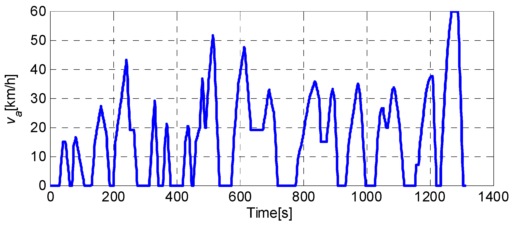
(1) First, the optimal results are obtained by PMP to optimize the gearshift command and torque distribution by considering drivability and fuel economy simultaneously. This is realized under China Typical City Cycle (CTCC), which offers an extracted gearshift map for approximate PMP.
(2) Second, the engine and motor piecewise linear models are introduced into the optimization of torque distribution, aiming to enhance the fuel and computation efficiencies. Based on the piecewise linear models, a computationally efficient energy management approach is then formulated with the extracted gearshift map.
(3) Lastly, the approximate Hamilton function is derived by piecewise linear models, and a control-oriented battery aging model is then incorporated by explicitly including the battery aging degradation into the design. The proposed strategy results in a better control performance for fuel economy and battery lifetime. This is indeed essential to ensure the potential in real-time control.

3.1. The Principle of PMP

As a global optimization method, PMP can be implemented by transforming the global optimization problem into instantaneous optimization. In this section, PMP is formulated for a parallel HEV to jointly optimize gearshift command and torque distribution. The optimization objective (Hamilton function) is formulated as follows (Equation (11)).
H ( u g ( t ) , S O C ( t ) , λ ( t ) ) = m ˙ f ( u g ( t ) ) + λ ( t ) S O ˙ C ( t )
where u g ( t ) consists of the optimal gearshift command and torque split, respectively; λ(t) is the co-state, and S O ˙ C ( t ) is the battery dynamic.
The dynamic of co-state is presented in Equation (12).
λ ˙ ( t ) = H ( u g   ( t ) ,   S O C ( t ) , λ ( t ) ) S O C ( t )
The state dynamic is shown in Equation (13).
S O ˙ C ( t ) = H ( u g ( t ) , S O C ( t ) , λ ( t ) ) λ
For optimality, to determine the optimal control, Equation (14) should be considered.
H ( u g * ( t ) ,   S O C ( t ) , λ * ( t ) ) H ( u g ( t ) ,   S O C ( t ) , λ * ( t ) )
The constraints should be satisfied in Equation (15) as follows.
{ T d e m ( t ) = T e ( t ) + T m ( t ) T m _ m i n ( n m ( t ) ) T m ( t ) T m _ m a x ( n m ( t ) ) 0 T e ( t ) T e _ m a x ( n e ( t ) ) 0 n m ( t ) n m _ m a x n e _ m i n n e ( t ) n e _ m a x S O C m i n S O C ( t ) S O C m a x
where Te(t) and Tm(t) are the engine torque and motor torque, respectively; Te_max(ne(t)) is the engine maximum torque at the current speed, Tm_max(nm(t)) is the motor maximum torque at the current speed, Tm_min(nm(t)) is the motor minimum torque at the current speed, nm_max is the motor maximum speed, ne_max and ne_min are the engine maximum and minimum speed, respectively, and SOCmin, SOCmax are the minimum and maximum SOC, respectively.

3.2. Optimization of Gearshift Command and Torque Distribution

To optimize the torque distribution, the torque demand at the input shaft of the transmission is adopted as shown in Equations (16) and (17).
F v = ( m g f ( ( v a 1 ) · ( v a 1 ) + ( v a > 1 ) ) + C D A 21.15 v a 2 + δ m v ˙
T d e m = F v / i g ( G e a r ) i 0
As previously mentioned, the optimal control input includes gearshift command and torque split. Thus, the optimal gearshift number g(t) can be obtained by Equation (18), which is constrained as seen in Equation (19). The value {−1,0,1} denotes downshift, maintaining, and upshift, respectively.
g ( t ) = g ( t 1 ) + sh ( t ) ,   s h ( t ) { 1 , 0 , 1 }
1 g ( t ) 5
Correspondingly, motor torque and gearshift command are selected as an optimal control input shown in Equation (20), which can be obtained by Equation (21) by satisfying the constraints in Equation (15).
u g ( t ) = [ s h ( t ) , T m ( t ) ]
u o p t ( t ) = arg min { H ( u g ( t ) ,   S O C ( t ) , λ ( t ) ) }
The engine torque is obtained as follows:
T e ( t ) = T d e m ( t ) T m ( t )
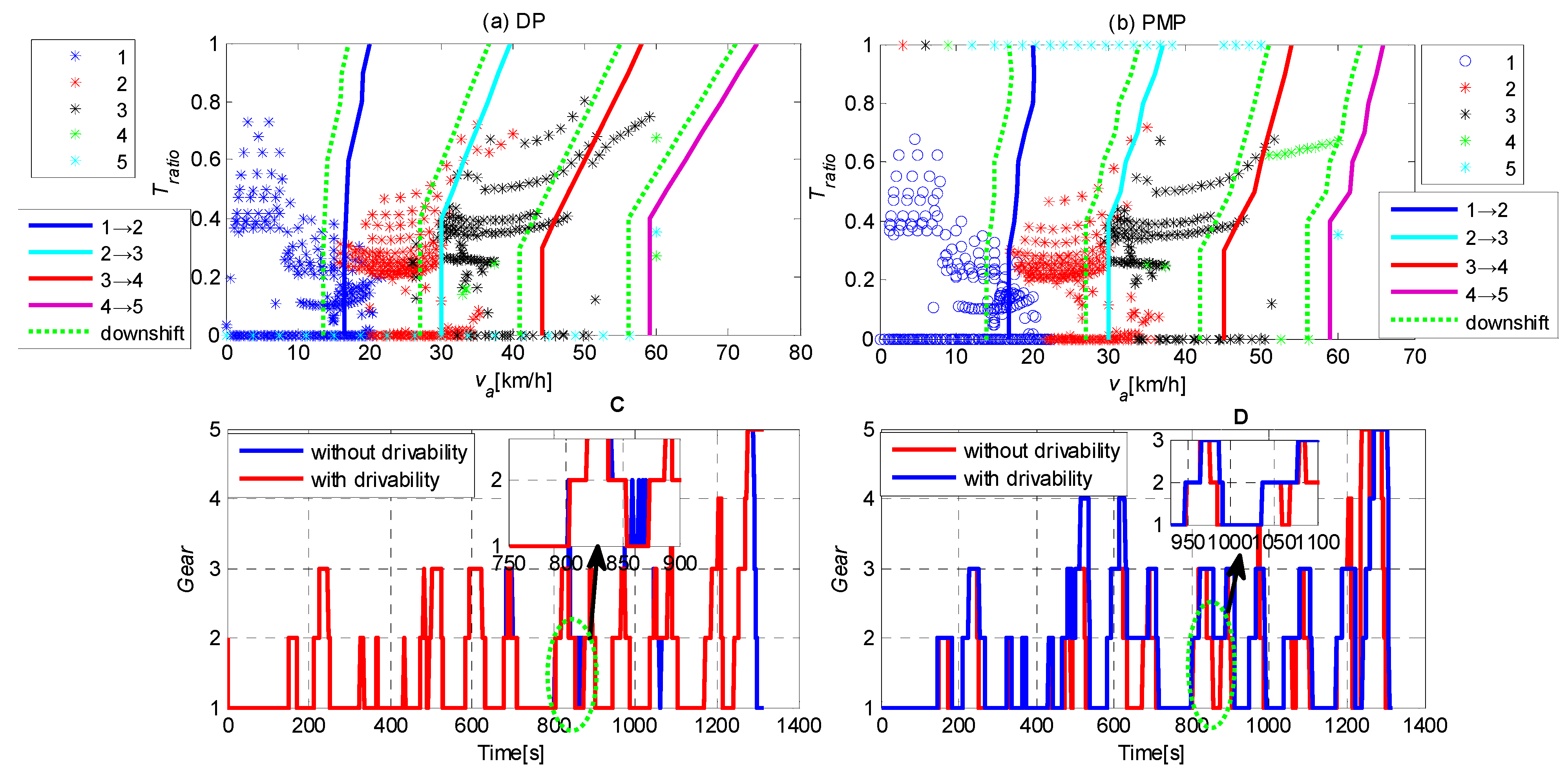
Based on the instantaneous optimization of PMP, the optimal gearshift command can be determined at each time instant with the driving cycle. An optimal torque distribution is then calculated accordingly. Furthermore, a gearshift map is extracted from the optimal results under a specific driving cycle, and employed in approximate PMP to obtain the optimal torque split.

3.3. Approximate PMP

A. Models Approximation
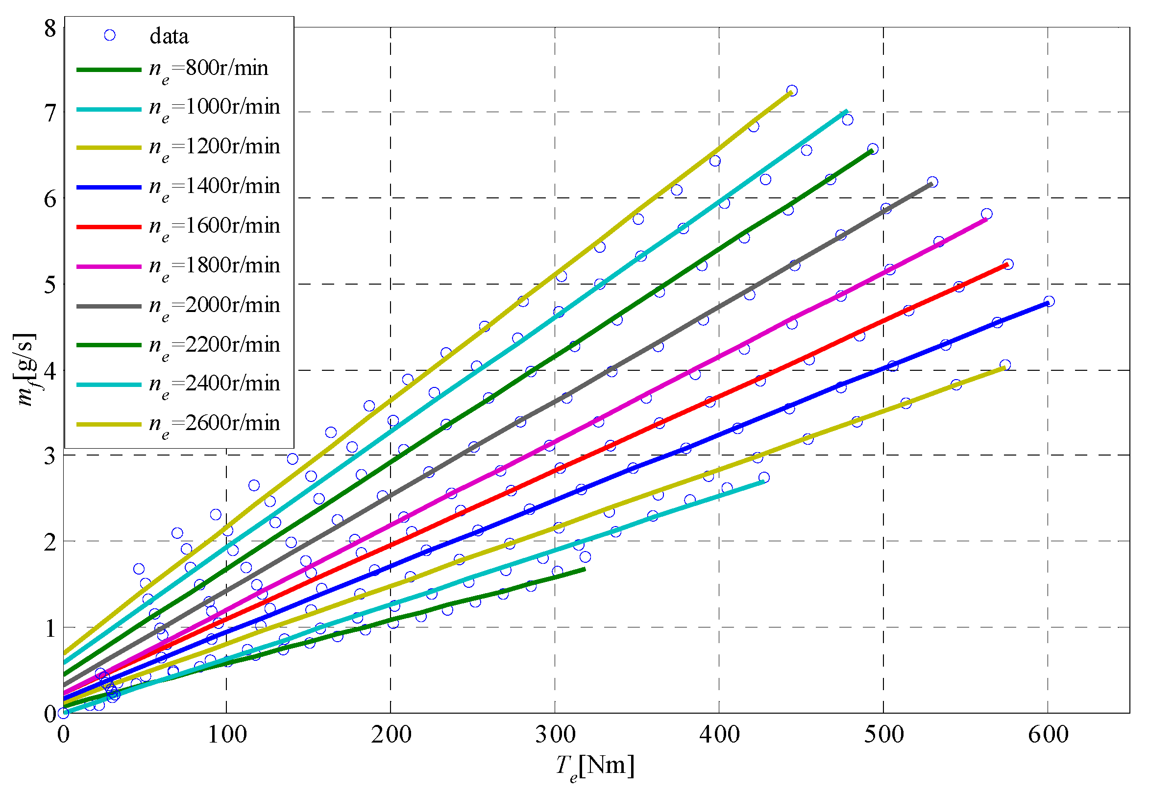
To derive the optimal control of PMP, the piecewise linear approximation is introduced to the engine fuel rate and the SOC derivative, which can be approximated as a function of the corresponding torque. As a result, the Hamiltonian function equals to a piecewise linear function as a summation of the two terms. The engine fuel rate can be approximated by engine torque, as shown in Equation (23). The fitting coefficients that depend on the engine speed are shown in Table 1.
m ˙ f = a ( n e ) T e + b ( n e )
where a(ne) and b(ne) are fitting coefficients related to the engine speed.
To further show the fitting results, the engine fuel rate fitting curve is created by the piecewise linear approximation, as shown in Figure 5.
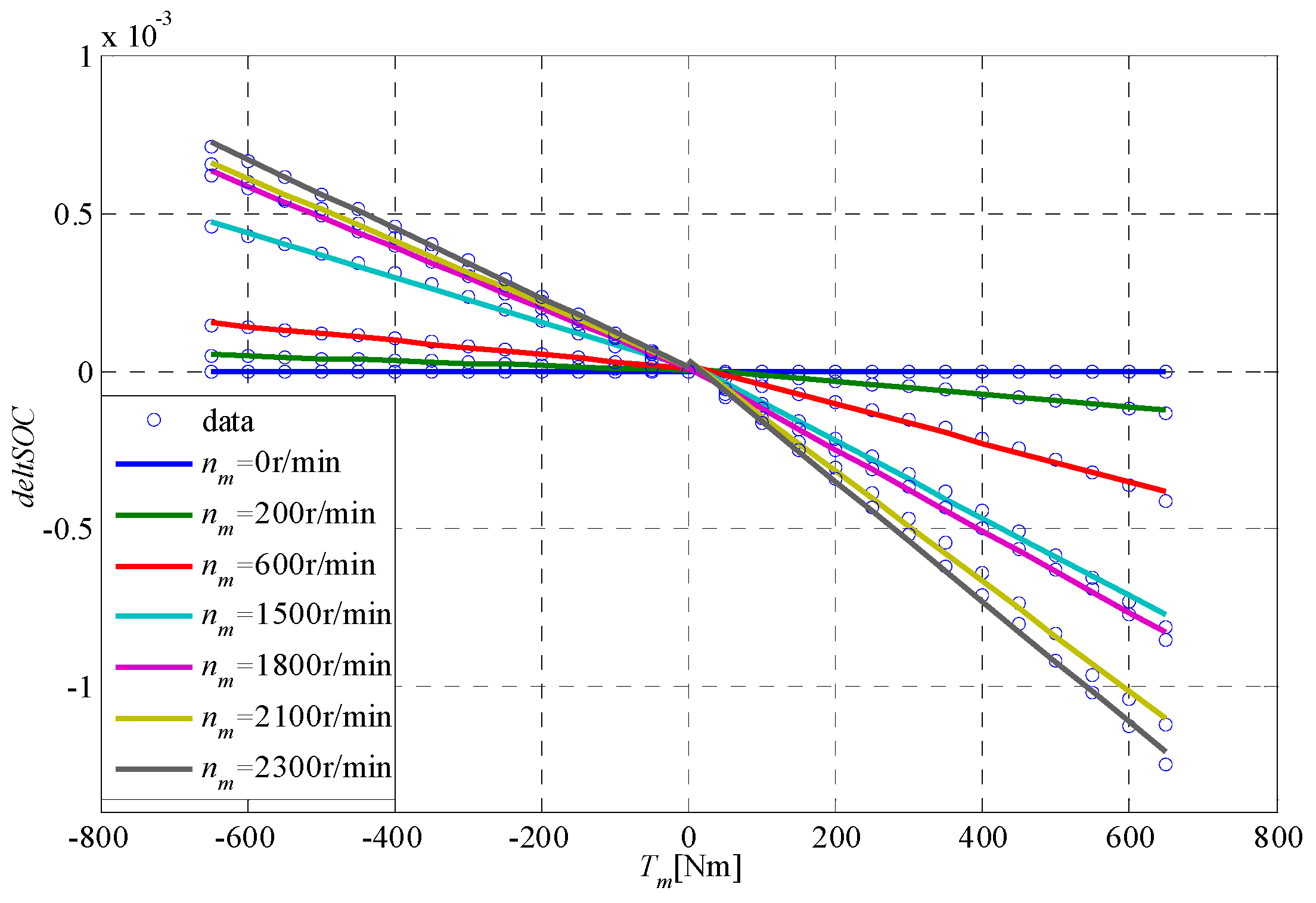
Similarly, the approximation of SOC derivative ( S O ˙ C ) is simplified by piecewise linear approximation, which can be presented as Equation (24).
S O ˙ C = { c ( n m ) T m + d ( n m ) T m > 0 0 T m = 0 g ( n m ) T M + f ( n m ) T m < 0
where c(nm), d(nm), g(nm), f(nm) are fitting coefficients associated with the motor speed.
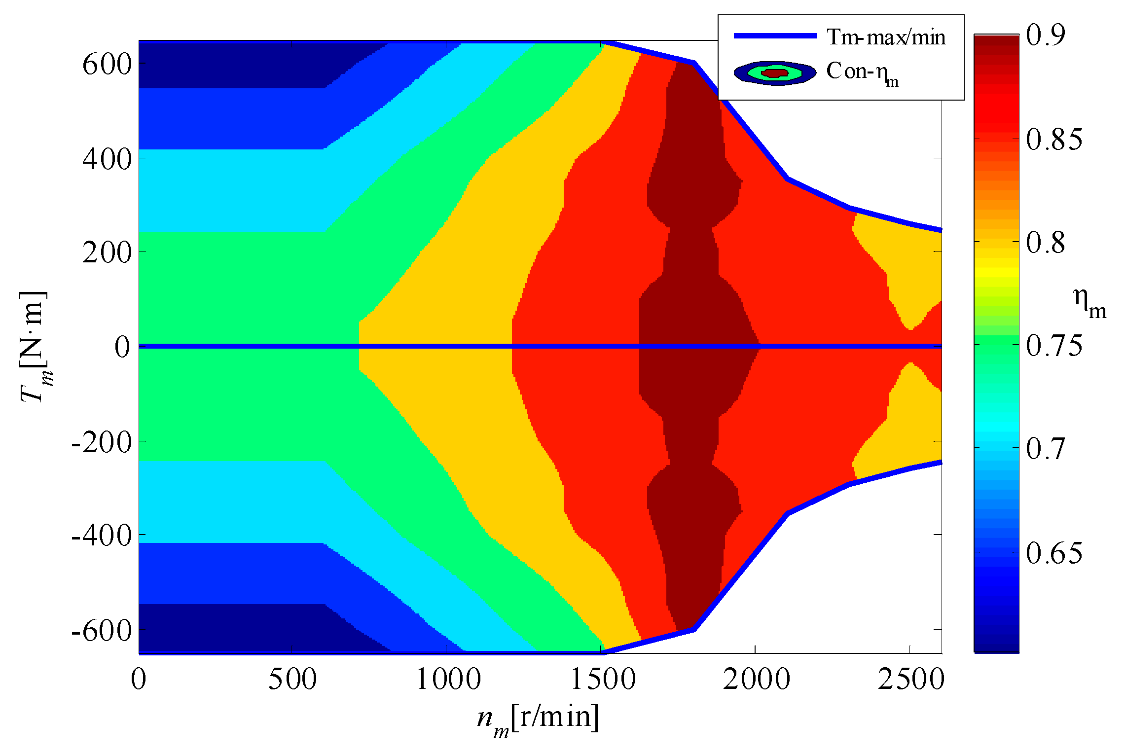
It is observed that the SOC derivative curve (deltSOC) is divided into two regions by the zero motor torque due to the opposite directions of power flow on both sides. The released battery power is equal to the output motor mechanical power, which is divided by the motor efficiency if the motor torque is positive. For the opposite direction, the absorbed battery power is equal to the motor power multiplied by the motor efficiency. To clearly present the results, the fitting curve is obtained by the piecewise linear approximation shown in Figure 6. It can be observed from Table 1; Table 2 that the R-square for engine fuel rate and SOC derivative is around 0.99, achieving a good fitting. Thus, piecewise linear fitting is considered to be an appropriate approximation approach.
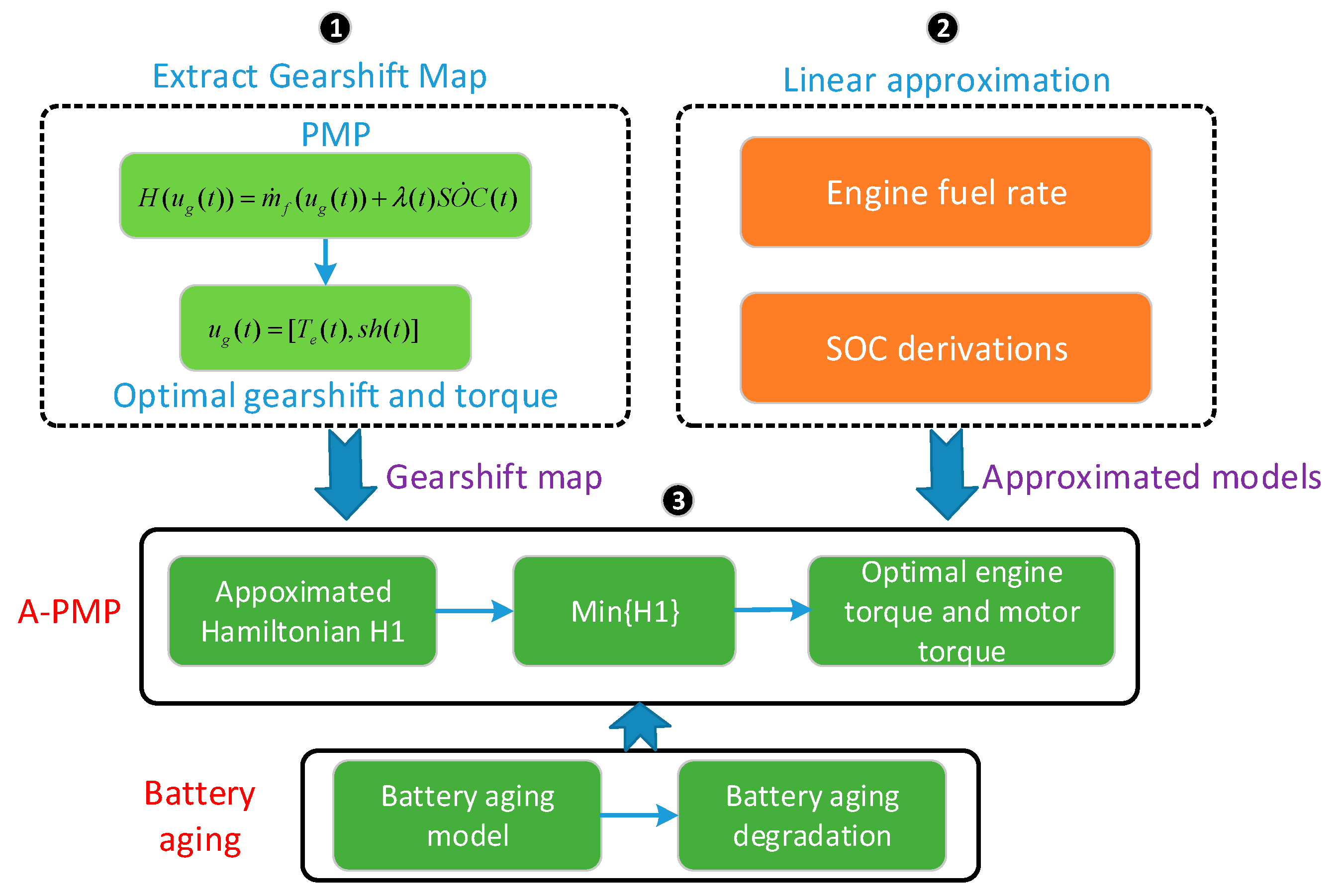
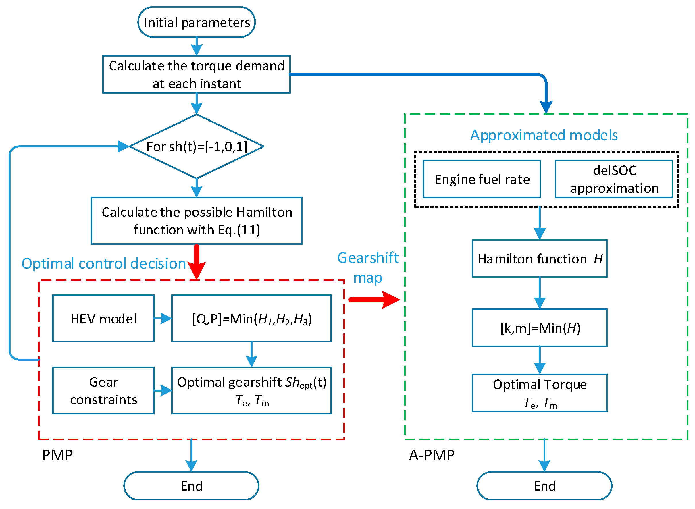
Based on the approximated engine and motor models, the detailed procedure of A-PMP is summarized in Figure 7.
B. A-PMP Formulation
Basically, the A-PMP has the same optimization structure as the standard PMP except for the instantaneous Hamiltonian optimization. By introducing linear approximation models to the local optimization problem and calculating the Hamiltonian; thus, the computational load is reduced. In the optimization scheme, the extracted gearshift map is employed in the A-PMP, and only the torque split is enforced by minimizing the Hamilton function. According to the principle of PMP, the Hamilton function is formulated as Equation (25).
H ( u ( t ) , S O C ( t ) , λ ( t ) ) = m ˙ f ( u ( t ) ) + λ ( t ) S O ˙ C
where u(t) includes the engine torque and motor torque (Nm).
Correspondingly, with the approximated models of Equations (23) and (24), the Hamilton function can be reformulated as a piecewise linear function shown in Equation (26).
H ( u ( t ) , λ ( t ) ) = { a ( n e ) T e + b ( n e ) + λ ( t ) [ c ( n m ) T m + d ( n m ) ] T m > 0 a ( n e ) T e + b ( n e ) T m = 0 a ( n e ) T e + b ( n e ) + λ ( t ) [ g ( n m ) T m + f ( n m ) ] T m < 0
The co-state dynamic is presented in Equation (27).
λ ˙ ( t ) = H ( u ( t ) , λ ( t ) ) S O C
The optimal engine and motor torque can be determined as follows.
T e = ( 1 R r a t i o ) T d e m
T m = R r a t i o · T d e m
where Rratio represents the motor torque divided by the total torque demand.
In this method, the torque distribution can be optimized by minimizing the instantaneous Hamilton function Equation (26) to guarantee the drivability.
[ T e _ o p t , T m _ o p t ] = arg min { H ( u ( t ) , λ ( t ) ) }
In addition, the optimal engine torque and motor torque should satisfy the following constraint.
T d e m ( t ) = T e _ o p t ( t ) + T m _ o p t ( t )
C. The Battery Aging Model
In this part, a multi-objective optimization problem by including the battery aging is constructed. To this aim, a battery aging model is required to blend the battery life into energy management. Generally, the battery is a complex electrochemical system. Two types of battery model are usually used to predict battery degradation: cycle life aging and calendar aging model. In this paper, a control-oriented battery cycle life aging is considered in optimizing the power split. For these models, electrochemical aging models and semi-empirical aging models are proposed in the literature [33,34]. The latter one is more suitable for HEV control design. Thus, we adopted the cycle semi-empirical battery aging model, presented in [35]. The battery pack adopts the LiFePO4 cells in this study. To measure the battery degradation, the battery capacity loss Qloss is presented in Equation (32).
Q l o s s = ( α S O C + β ) exp ( E a + η I r a t e R g T ) A h z
where Q l o s s is the battery capacity loss (%), α, β and η are the fitting coefficients related to SOC, and Ea is the activation energy (J/mol), Rg is the gas constant, T is the battery temperature in Kelvin [K], Ah is the accumulated charge throughput, i.e., the total amount of charge that can flow in and out of the battery during its operation, I r a t e is the current rate, z is the power law factor.
The accumulated charge throughput is calculated in Equation (33) and I r a t e is defined as the ratio of the current (A) to the nominal charge capacity (Ah) in Equation (34).
A h = 1 3600 0 t | I b ( t ) | d t
I r a t e = I b ( t ) Q
where I b ( t ) is the current during the trip.
For an HEV application, it is generally realized that the battery should be replaced with a new one when the battery capacity reaching 80% of the original value [36]. Therefore, the end of life is defined as 20% loss of capacity. The nominal conditions defined in this study are Irate,norm = 2.5[1/h], SOCnorm = 0.35, and Tnorm = (273.15 + 25) K [37], and the nominal battery life is then calculated in Equation (35). In this paper, the battery temperature is assumed to be constant (25 °C).
Γ ( I r a t e , n o r m , S O C n o r m , T n o r m ) = [ 20 ( α S O C n o r m + β ) · exp ( E a + η I r a t e , n o r m R g T n o r m ) ] 1 z
The battery life is defined in Equation (36) in terms of Ah-throughput related to specific operating conditions.
γ ( I r a t e , S O C , T ) = [ 20 ( α S O C + β ) · exp ( E a + η I r a t e R g T ) ] 1 Z
Thus, the severity factor is obtained using Equation (37) for a given cycle, which indicates the battery relative aging effect.
σ ( I r a t e , S O C , T ) = Γ ( I r a t e , n o r m , S O C n o r m , T n o r m ) γ ( I r a t e , S O C , T )
To consider the battery aging, the effective Ah-throughput can be expressed by Equation (38). Generally, minimizing the battery aging degradation is to minimize the effective Ah-throughput.
A h e f f ( t ) = 0 t σ ( I r a t e , S O C , T ) | I b ( t ) | d t
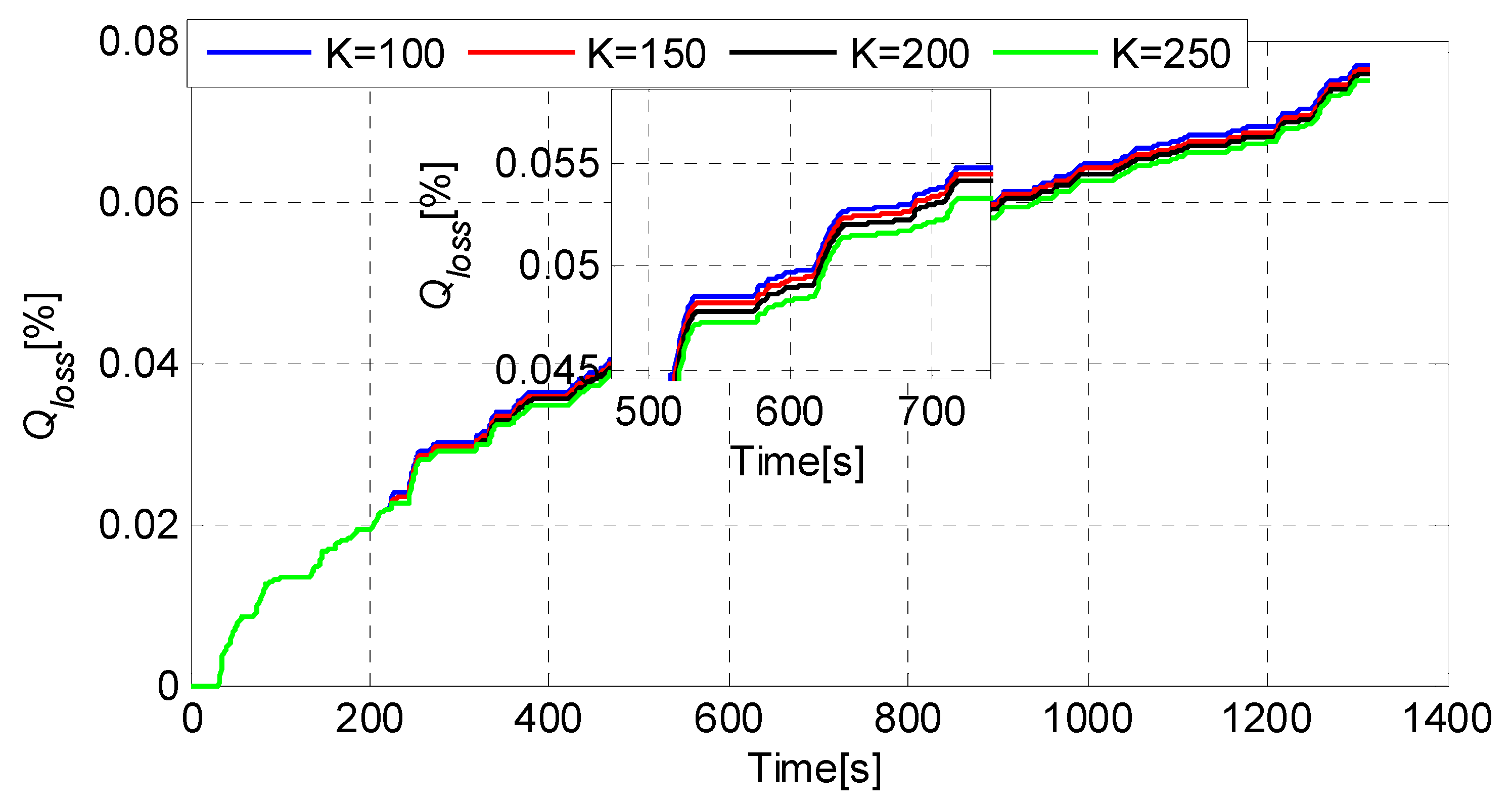
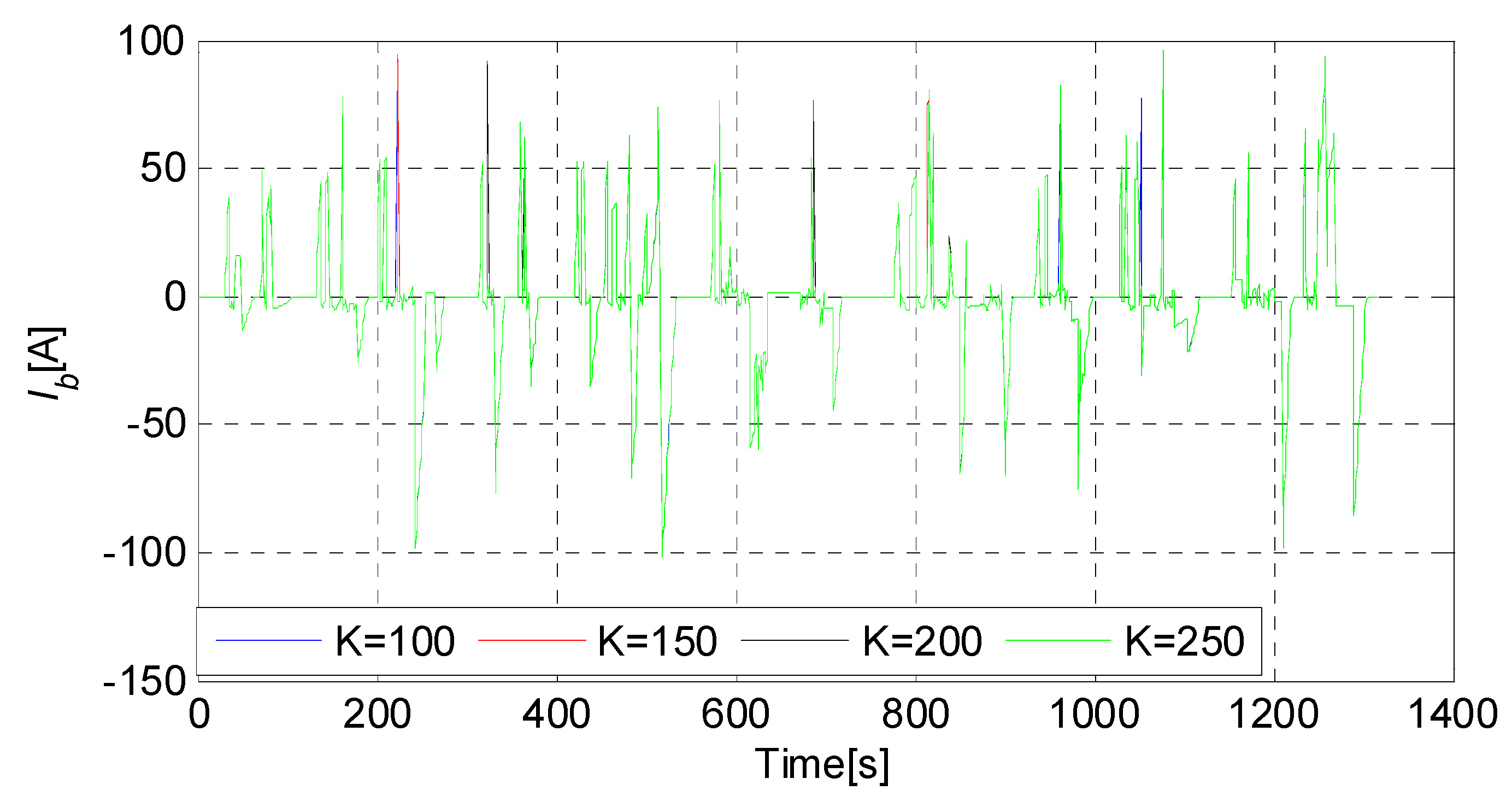
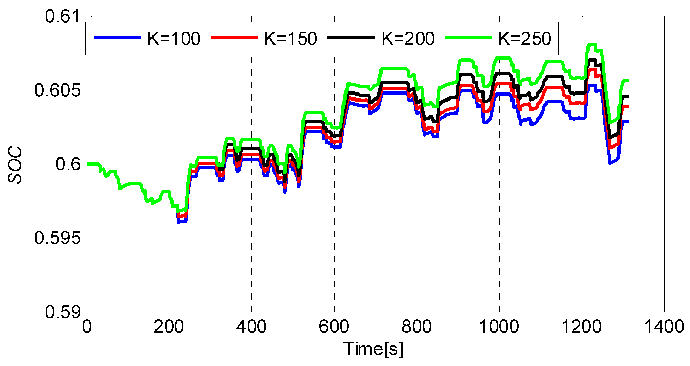
Therefore, the approximated Hamilton function is reformulated in Equation (39) by considering fuel economy and battery aging simultaneously. The optimal control of A-PMP is then solved by minimizing Equation (39).
H ( u ( t ) , λ ( t ) ) = { a ( n e ) T e + b ( n e ) + λ ( t ) [ c ( n m ) T m + d ( n m ) ] + K C a σ ( I r a t e , S O C , T ) Γ ( I r a t e , n o r m , S O C n o r m , T n o r m ) | I b ( t ) | T m > 0 a ( n e ) T e + b ( n e ) + K C a σ ( I r a t e , S O C , T ) Γ ( I r a t e , n o r m , S O C n o r m , T n o r m ) | I b ( t ) | T m = 0 a ( n e ) T e + b ( n e ) + λ ( t ) [ g ( n m ) T m + f ( n m ) ] + K C a σ ( I r a t e , S O C , T ) Γ ( I r a t e , n o r m , S O C n o r m , T n o r m ) | I b ( t ) | T m < 0
where K is the weight factor for battery aging cost, Ca is the ratio of battery replacement cost of 1 kg of gasoline.

4. Results and Discussion

In this section, piecewise linear approximations of the engine fuel rate and SOC derivative are proposed to solve the Hamiltonian optimization. To show the workings of the design, a set of simulations are conducted and the performance of the A-PMP is compared with the DP and PMP.
The energy management optimization (gearshift command and torque distribution) is firstly conducted using DP and PMP under China’s typical city condition (CTCC) by incorporating the drivability into the EMS. CTCC represents a typical city driving condition in China, and as a benchmark, DP is employed to optimize the gearshift command and torque split. To incorporate the drivability, the gearshift map is extracted from the optimal results by PMP and then employed in the PMP/A-PMP. To verify the effectiveness of the proposed EMS, a commercial hybrid electric bus model is adopted and its parameters are given in Table 3. It is noted that the models and algorithms are implemented using MATLAB m.file.
To assess the drivability for the EMS, we compare the performance of the PMP with DP in terms of gearshift command and torque split. First, an extracted gearshift map is obtained by the PMP under CTCC. Second, with the gearshift map, the approximate PMP based on approximated models is evaluated. Lastly, the performance of A-PMP including battery aging is analyzed under CTCC. Figure 8 shows the driving cycle for evaluation.

4.1. The DP-based Energy Management Formulation

According to the bellman principle, DP can obtain a global optimal solution that can be used as a benchmark. Thus, in this case, DP is firstly formulated to optimize the power split for parallel HEV. The objective function is formulated with respect to the fuel consumption and drivability (gearshift command) as shown in Equation (40).
J = m i n k = 0 N L k ( x ( k ) , u ( k ) ) = m i n   k = 0 N β m ˙ f ( u ( k ) ) + γ | d ( k ) |
s . t   Equation   ( 15 )
where m ˙ f ( u ( k ) ) is the fuel consumption at k instant, γ | d ( k ) | is the penalty function to avoid frequent gearshift, and β and γ are the weight factors.
According to the problem formulation, the state includes the battery SOC and gear number, and the control variables are selected as the torque ratio (defined below) and gearshift command, which are shown in Equations (42) and (43), respectively.
x ( k ) = [ S O C ( k ) g ( k ) ]
u ( k ) = [ r ( k ) d ( k ) ]
where k is the time instant, x ( k ) is the state variable at time instant k, SOC(k) is the battery state of charge at current instant, g(k) is the gear number at time instant k, g ( k ) [ 1 , 2 , 3 , 4 , 5 ] ,   u ( k ) is the control variable, r(k) is defined as the ratio of the motor torque to the total torque demand, d(k) is the gearshift command, and d ( k ) [ 1 , 0 , 1 ] is defined as follows.
d ( k ) = { 1             u p s h i f t 0       m a i n t a i n 1     d o w n s h i f t
The gear number at k + 1 instant is derived by Equation (45).
g(k + 1) = g(k) + d(k)
DP is a multi-stage optimization process, and its optimal solution can be obtained by a numerical method. It is necessary to solve the optimal problem backward duration of the trip from the future state to find the initial control input in feasible region. Thus, the state and control variable should be gridded at a certain range as presented in Table 4 and satisfy corresponding constraints. To this aim, the time step is set as 1 s. As such, DP usually suffers from heavy computing time, because the computation burden increases as the dimension of the system states raise.

4.2. Extracting the Gearshift Map

The effectiveness of the gearshift command and torque distribution optimization is evaluated under CTCC, computed by the DP and PMP. As a benchmark, DP is employed to obtain an optimal solution over an entire driving cycle. It is well known that PMP mainly aims at minimizing the instantaneous Hamilton and thus produces frequent gearshift, especially during frequent velocity changes. To prevent this phenomenon from occurring, a gearshift map is firstly extracted from the optimal operating points obtained by PMP. Specifically, the upshift line is the boundary of operation points between the adjacent gears, which is composed of the lower line and the upper line. The lower line is vertical and the upper line leans towards the right to improve the dynamic performance. The upshift line moves leftwards about 3 km/h, which is defined as the downshift line to avoid the frequent gearshift.
Figure 9 shows the optimal gearshift map for both DP and PMP approaches under CTCC. The optimal gearshift patterns for both approaches are very consistent. Particularly, we can note from ‘D’ in Figure 9 that there is a frequent gearshift phenomenon without consideration of drivability. Therefore, the PMP with the extracted gearshift map can effectively avoid frequent gearshift. This demonstrates the feasibility of the standard PMP in determining the gearshift schedule. Table 5 further summarizes the optimization performance. It is noted that the number of gearshift events is reduced by considering the drivability under CTCC relative to the one without incorporating drivability. It can also be observed that the average fuel economy of the standard PMP with the gearshift map decreases around 5%, compared with the one without considering the drivability. The reason is that the gearshift of the standard PMP is approximated by considering the drivability. Additionally, the standard PMP achieves near-optimal fuel economy compared to the DP.

4.3. Optimization Performance Assessment

To assess the performance of the proposed energy management, the extracted gearshift map from PMP is adopted for both PMP and A-PMP to determine the torque distribution. The initial SOC is set to 0.6 for all cases. The co-state values are chosen as −9100 and −8000 by a trial and error method for PMP and A-PMP under the CTCC.

4.3.1. The Performance Index

(1) Fuel Consumption
In simulation results, the fuel economy for different energy management strategies is assessed. We adopted SOC compensated fuel consumption (see Equations (46) and (47)) due to the deviations of final SOC value from the reference one.
E Δ s o c = ( S O C f S O C 0 ) · Q m a x · 3600 · N c e l l U o c v _ d i s c h a r g e d ( 1 S O C )
F C Δ s o c _ c o m p = F C E Δ s o c E d i e s e l η d i e s e l η I C E η E M ρ d i e s e l d c y c l e · 10 5
where E Δ S o C is the energy produced by SOC deviation (J), Qmax is the capacity of battery (Ah), Ncell is the cell number of battery, SOC0, SOCf is the SOC initial and final value, respectively, Uocv_discharge is the cell voltage (V), Ediesel is the energy content of diesel fuel (J/kg), η d i e s e l is the efficiency of conversion from diesel engine output to the motor input, η I C E is the diesel engine efficiency, η E M is the motor efficiency, ρdiesel is the density of diesel (0.835 kg/L), dcycle is the distance traveled (m). F C Δ S o C _ c o m p is the SOC compensated fuel consumption (L/100 km), FC is the actual fuel consumption without calculating SOC compensated fuel (kg).
(2) Final SOC
The final SOC at the end of the cycle is employed to evaluate the performance of SOC charge-sustainability.
(3) Drivability Performance
The drivability performance indicates that the gearshift would not be ‘hunting’, that is, the rapid shifting between the same two gears. Thus, better drivability performance means less gearshift event without frequent gearshift (e.g., frequent downshift and upshift).
(4) Computation Efficiency
The computation efficiency indicates the computation time for PMP/A-PMP, while the consumed time for DP over an entire driving cycle. Thus, less computation time implies that a higher computation efficiency is obtained.

4.3.2. Optimization Performance analysis

To achieve a better understanding of the proposed method, the results under CTCC are detailed in Figure 10; Figure 11. Figure 10 shows the state trajectory using three different methods, i.e., DP, PMP, and A-PMP. The gearshift pattern remains consistent for PMP and A-PMP since they adopted the same gearshift map that is extracted from the PMP. It is observed that the gear number shows a slight difference for DP and PMP/A-PMP, since the extracted gearshift schedule from PMP is adopted in PMP/A-PMP, whereas both gearshift command and torque distribution are co-optimized by DP. Additionally, the torque distribution (e.g., engine torque, motor torque) and SOC exhibit a similar pattern for PMP and A-PMP. Consequently, the torque trajectory between A-PMP and PMP is almost consistent, so that the approximation of the PMP by the A-PMP was confirmed. However, these traces are different from the results obtained from DP. This is due to the fact that DP is considered as a global optimization method, achieving the best fuel economy.
Figure 11 displays the engine and motor operation points for three approaches. It is shown that the engine can operate in higher efficiency regions (0.35–0.4) for three approaches, whereas the engine efficiency map for A-PMP is smooth due to the linear approximation. Different from the interpolation method adopted in previous works, the severe distortion to the engine efficiency map can be avoided by using the proposed piecewise linear approximation. It is an important factor in the optimization process. This is interpreted as the main reason why the A-PMP achieves a better fuel economy compared to the numerical PMP. For the linear approximated map, the engine efficiency increases monotonically with the engine torque at each speed.
To further demonstrate the merits of the proposed approach, the comparison for three control strategies is summarized in Table 6. It is noted that PMP is conducted by an interpolation method and A-PMP adopts the piecewise linear approximation for comparison study. PMP and A-PMP adopt the same gearshift map extracted from PMP. The computation time of numerical PMP is 7.55 s over the entire driving cycle, while it only takes 3.98 s for A-PMP. It is also shown that the A-PMP with drivability improves the fuel economy by 3.5% compared with the PMP under the same headline, whereas it achieves a fuel economy reduction of about 3.9% relative to the DP. The SOC deviation between the final SOC and initial SOC is less than 0.01 for both approaches. The final SOC converges to 0.6 at the end of the cycle. Thus, the SOC charge-sustainability is well maintained. On the other hand, the gearshift events are reduced using the extracted gearshift map as treated to the one without considering drivability. Due to the utilization of the extracted gearshift map, there is no frequent gearshift for both PMP and A-PMP in the optimization process, guaranteeing good drivability, especially in real-time control. As a result, the computation efficiency can be improved for A-PMP, and we can obtain good accuracy. It is concluded that the fast computation speed of A-PMP also renders that it can easily be utilized for real-time control. Moreover, it is verified that the piecewise linear approximation of the fuel rate provides an accurate approximation in terms of the efficiency map.
The computation time of DP, PMP and A-PMP are obtained over the 1315 s driving cycle.
As a consequence, the approximate PMP utilizing the piecewise linear approximation achieves better accuracy with higher computation efficiency while ensuring the better fuel efficiency as compared with the PMP. No frequent gearshift occurs for PMP with drivability, and the drivability is also guaranteed by using the extracted gearshift map for both PMP and A-PMP. This means that the proposed approach is potentially implementable in real time.

4.3.3. Battery Aging Performance Analysis

The gearshift map is firstly extracted by PMP and then employed in A-PMP. To obtain the best fuel economy, the gearshift map is extracted only considering the fuel economy. In the A-PMP, we consider the battery degradation. The reason is that there is a tradeoff between fuel consumption and battery degradation. It is hard to select a proper weight between fuel consumption and battery degradation. The selection of weight factor depends on the design objective, that is, if one wants to obtain better fuel economy, then the smaller weight K is selected, or, if one wants to get a better battery lifetime, then the larger weight K is needed. Thus, there is a tradeoff between fuel economy and battery degradation. For our work, the gearshift map is obtained to achieve the best fuel economy, so battery degradation is not considered in extracting the gearshift map. Then, the battery degradation is considered in A-PMP to investigate the tradeoff between fuel economy and battery degradation.
We analyze the battery aging performance with the extracted gearshift map. The A-PMP strategy including the battery aging is conducted by minimizing Equation (39). The parameters are given in Table 7 [35]. Different K are chosen for simulations (note that K is the weight factor for battery aging cost). The effect of K on battery capacity loss under the CTCC is presented in Figure 12. It is clear that the battery capacity loss decreases as K expands since more battery aging is considered for a larger K to slow down the battery aging degradation, leading to less battery power used and more fuel consumed. On the other hand, the current curve during operation is reported in Figure 13. Similarly, for a larger K, the battery yields smaller average current value for the operation cycle. Since the most important aging effect in HEVs takes place in SOC deviations for a given driving cycle, the SOC trajectory is also shown in Figure 14. It is obvious that the SOC tends to increase due to less battery power utilized as K increases. As a result, lower battery degradation is achieved.
In summary, taking into account the battery aging has a significant effect on the battery lifetime depleted during the cycle. By adding the battery aging cost, a tradeoff between fuel economy and expected battery life is obtained. Increasing the K will reduce the battery aging degradation, and thus longer the battery life. Thus, it is necessary to include the battery aging in the optimization process.
To further display the effect of K on the fuel economy and battery aging, the results with different K are summarized in Table 8. It can be observed that the battery aging is weighted more as the K increases; thus, less effective Ah-throughput over the cycle and more aging is expected, whereas more fuel consumption is observed. In addition, when only fuel consumption is considered in the optimization process without including the battery aging (K = 0), we can observe the best fuel economy.

4.4. Summary of Results

The average fuel reduction of PMP is approximately 5% less compared to the one without taking drivability into account. By introducing the extracted gearshift map, the excessive frequent gearshift is avoided. Moreover, the approximate PMP with piecewise linear approximation can effectively improve the computation efficiency while ensuring a better accuracy than that of the PMP. The approximation method is considered to be an effective approach without loss of accuracy. As a result, the approximate PMP with piecewise linear models yields more potentials in real-time control. Moreover, the fuel economy of A-PMP decreases, whereas the battery aging degradation can be low by including the battery aging.

5. Conclusions and Future Work

In this work, a computationally efficient energy management approach based on approximate PMP with piecewise linear models for a parallel HEV is proposed. The proposed method optimizes the gearshift command and torque distribution simultaneously. As a consequence, better fuel efficiency is obtained with a good drivability to avoid frequent gearshift while improving the computation efficiency. The proposed design also considers the battery aging, which leads to potentials in real-time applications.
We can further enumerate the findings as follows. First, the gearshift map is efficiently extracted with PMP by optimizing gearshift command and torque distribution to avoid the frequent gearshift. The drivability and fuel economy are both considered by comparing to the DP-based strategy under CTCC. Second, an approximate energy management strategy with piecewise linear models for a parallel HEV is developed. Consequently, the proposed method presents a computation efficiency by 50% as compared with the PMP. Moreover, the fuel economy of A-PMP is very close to the one of PMP, indicating good accuracy of the proposed approximation method. PMP and A-PMP share a similar pattern in the torque distribution, which reveals that the proposed approach guarantees the overall performance in terms of fuel economy, SOC charge-sustainability, and computation efficiency. Finally, a battery capacity degradation model in the A-PMP is introduced to consider the fuel consumption and battery aging degradation simultaneously. The results show that the A-PMP can lower the battery aging, but the fuel economy is decreased. This reveals that there is a tradeoff between fuel economy and battery aging degradation. This study is a preliminary exploration of modeling an EMS using the A-PMP. Further studies will be done to develop adaptive PMP to optimize energy management in various driving cycles. Another possible extension is to solve a more general energy management formulation by considering both the engine and the catalytic converter temperature as well as including the emission of pollutants in the objective function. Seasonal weather changes, individual driving factors, and the impact of infrastructural communication can also be considered by utilizing a set of driving cycles in the future work. Moreover, experimental tests will be carried out to ensure the effectiveness in more general environments. Additionally, the battery cycle aging model is mainly incorporated into the energy management without considering the battery calendar aging model. It is necessary to consider the battery calendar aging model with energy management for longer mileage in future work.

Author Contributions

Conceptualization and methodology, F.Z.; software, L.W.; data analysis, S.C.; validation, H.P.; investigation, Y.C.; writing—original draft preparation, F.Z.; writing—review and editing, L.W.; S.C.; H.P. and Y.C. All authors have read and agreed to the published version of the manuscript.

Funding

This work was supported in part by the National Natural Science Foundation of China (Grant No.51905419), the Natural Science Basic Research Program in Shaanxi Province of China (Grant No.2019JQ-503) and the Fundamental Research Fund for the Central Universities of China (Grant No.300102229514).

Conflicts of Interest

The authors declare no conflict of interest.

Nomenclatures

Abbreviations
HEVshybrid electric vehicles
PMPPontryagin’s Minimum Principle
DPdynamic programming
EMSsenergy management strategies
PHEVplug-in HEV
AMTautomated mechanical transmission
SOCstate of charge
CTCCChina typical city cycle
FCfuel consumption
ECMSEquivalent consumption minimization strategy
Symbols
neengine speed
Teengine torque
ηeengine efficiency
αengine throttle opening
Temax(ne)engine maximum torque at the current speed
nmmotor speed
Tmmotor torque
ηmmotor efficiency
Pbrequired battery power
Rinbattery resistance
Vocopen circuit voltage
Qmaxmaximum capability
Touttransmission output shaft torque
Tintorque of the transmission input shaft
ηGRtransmission efficiency
iggear ratio of each transmission gear
i0gear ratio of the final drive
winangular velocity of the transmission input shaft
woutangular velocity of the transmission output shaft
Tdem(t)torque demand at the input shaft of the transmission
CDair resistance (drag) coefficient
Afrontal area
va(t)vehicular velocity
mcomplete vehicle curb mass
frolling resistance coefficient
δcorrection coefficient of the rotating mass
rwheel radius
ninspeed of the transmission input shaft
λ (t)co-state
Pb(ug(t))battery power
ug(t)the optimal torque and gearshift command
Tm_min(nm(t))motor minimum torque at the current speed
Tm_max(nm(t)motor maximum torque at the current speed
Te_max(ne(t))engine maximum torque at the current speed
nm_maxmotor maximum speed
ne_maxengine maximum speed
ne_minengine minimum speed
SOCminminimum SOC
SOCmaxmaximum SOC
sh(t)gearshift command
g(t)optimal gear number
u(t)engine torque and motor torque
Te_optengine torque for the flexible torque demand
Tm_optmotor torque for the flexible torque demand
E△SOCenergy produced by SOC deviation
SOCfSOC final value
SOC0SOC initial value
Ncellcell number of battery
FC△SOC_compSOC compensated fuel consumption
Uocv_dischargecell voltage
Edieselenergy content of diesel fuel
ηdieselefficiency of conversion from diesel energy to electricity
ηICEdiesel engine efficiency
ηEMmotor efficiency
ρdieseldensity of diesel
dcycledistance traveled
Qlossbattery capacity loss
α β η fitting coefficients related to SOC
Eaactivation energy
Rggas constant
Tbattery temperature in Kelvin
Ahaccumulated charge throughput
Iratecurrent rate
zpower law factor
Rratiomotor torque divided by the total torque demand
Ib(t)current during the trip
Kweight factor for battery aging cost
Caratio of battery replacement cost of 1 kg of gasoline
m ˙ f ( u ( k ) ) fuel consumption at k instant
x(k)state variable at time instant k
SOC(k)battery state of charge at current instant
g(k)gear number at time instant k
u(k)control variable
r(k)ratio of the motor torque to the total torque demand
d(k)gearshift command

References

  1. Qin, Y.; Tang, X.; Jia, T.; Duan, Z.; Zhang, J.; Li, Y.; Zheng, L. Noise and vibration suppression in hybrid electric vehicles: State of the art and challenges. Renew. Sustain. Energy Rev. 2020, 124, 109782. [Google Scholar] [CrossRef]
  2. Zhang, F.; Hu, X.; Langari, R.; Cao, D. Energy management strategies of connected HEVs and PHEVs: Recent progress and outlook. Prog. Energy Combust. Sci. 2019, 73, 235–256. [Google Scholar] [CrossRef]
  3. Zhang, F.; Wang, L.; Coskun, S.; Pang, H.; Cui, Y.; Xi, J. Energy Management Strategies for Hybrid Electric Vehicles: Review, Classification, Comparison, and Outlook. Energies 2020, 13, 3352. [Google Scholar] [CrossRef]
  4. Onori, S.; Serrao, L.; Rizzoni, G. Hybrid Electric Vehicles: Energy Management Strategies; Springer: Berlin/Heidelberg, Germany, 2016. [Google Scholar]
  5. Jeong, J.; Kim, N.; Lim, W.; Park, Y.-I.; Cha, S.W.; Jang, M.E. Optimization of power management among an engine, battery and ultra-capacitor for a series HEV: A dynamic programming application. Int. J. Automot. Technol. 2017, 18, 891–900. [Google Scholar] [CrossRef]
  6. Donitz, C.; Vasile, I.; Onder, C.; Guzzella, L. Dynamic Programming for Hybrid Pneumatic Vehicles. In Proceedings of the 2009 American Control Conference, St. Louis, MO, USA, 10–12 June 2009; IEEE: New York, NY, USA, 2009; pp. 3956–3963. [Google Scholar] [CrossRef]
  7. Lin, C.-C.; Peng, H.; Grizzle, J.; Kang, J.-M. Power management strategy for a parallel hybrid electric truck. IEEE Trans. Control. Syst. Technol. 2003, 11, 839–849. [Google Scholar] [CrossRef] [Green Version]
  8. Fares, D.; Chedid, R.; Panik, F.; Karaki, S.; Jabr, R.A. Dynamic programming technique for optimizing fuel cell hybrid vehicles. Int. J. Hydrogen Energy 2015, 40, 7777–7790. [Google Scholar] [CrossRef]
  9. Yang, Y.; Pei, H.; Hu, X.; Liu, Y.; Hou, C.; Cao, D. Fuel economy optimization of power split hybrid vehicles: A rapid dynamic programming approach. Energy 2019, 166, 929–938. [Google Scholar] [CrossRef]
  10. Van Harselaar, W.; Schreuders, N.; Hofman, T.; Rinderknecht, S. Improved Implementation of Dynamic Programming on the Example of Hybrid Electric Vehicle Control. IFAC-PapersOnLine 2019, 52, 147–152. [Google Scholar] [CrossRef]
  11. Li, G.; Görges, D. Energy management strategy for parallel hybrid electric vehicles based on approximate dynamic programming and velocity forecast. J. Frankl. Inst. 2019, 356, 9502–9523. [Google Scholar] [CrossRef]
  12. Zhou, W.; Yang, L.; Cai, Y.; Ying, T. Dynamic programming for New Energy Vehicles based on their work modes part I: Electric Vehicles and Hybrid Electric Vehicles. J. Power Sources 2018, 406, 151–166. [Google Scholar] [CrossRef]
  13. Onori, S.; Tribioli, L. Adaptive Pontryagin’s Minimum Principle supervisory controller design for the plug-in hybrid GM Chevrolet Volt. Appl. Energy 2015, 147, 224–234. [Google Scholar] [CrossRef]
  14. Kim, N.; Cha, S.W.; Peng, H. Optimal Equivalent Fuel Consumption for Hybrid Electric Vehicles. IEEE Trans. Control. Syst. Technol. 2011, 20, 817–825. [Google Scholar] [CrossRef]
  15. Kim, N.; Rousseau, A.; Lee, D. A jump condition of PMP-based control for PHEVs. J. Power Sources 2011, 196, 10380–10386. [Google Scholar] [CrossRef]
  16. Lee, W.; Jeoung, H.; Park, D.; Kim, N. An Adaptive Concept of PMP-Based Control for Saving Operating Costs of Extended-Range Electric Vehicles. IEEE Trans. Veh. Technol. 2019, 68, 11505–11512. [Google Scholar] [CrossRef]
  17. Li, X.; Wang, Y.; Yang, D.; Chen, Z. Adaptive energy management strategy for fuel cell/battery hybrid vehicles using pontryagin’s minimal principle. J. Power Sources 2019, 440, 227105. [Google Scholar] [CrossRef]
  18. Xie, S.; Hu, X.; Xin, Z.; Brighton, J. Pontryagin’s Minimum Principle based model predictive control of energy management for a plug-in hybrid electric bus. Appl. Energy 2019, 236, 893–905. [Google Scholar] [CrossRef] [Green Version]
  19. Ghasemi, M.; Song, X. Powertrain Energy Management for Autonomous Hybrid Electric Vehicles with Flexible Driveline Power Demand. IEEE Trans. Control. Syst. Technol. 2018, 27, 2229–2236. [Google Scholar] [CrossRef]
  20. Park, K.; Son, H.; Bae, K.; Kim, Y.; Kim, H.; Yun, J.; Kim, H. Optimal Control of Plug-In Hybrid Electric Vehicle Based on Pontryagin’s Minimum Principle Considering Driver’s Characteristic. In Proceedings of the 3rd International Conference on Vehicle Technology and Intelligent Transport Systems, Porto, Portugal, 22–24 April 2017; Scitepress: Setúbal, Portugal, 2017; Volume 2, pp. 151–156. [Google Scholar]
  21. Zheng, C.H.; Xu, G.Q.; Park, Y.I.; Lim, W.S.; Cha, S.W. Comparison of PMP and DP in fuel cell hybrid vehicles. Int. J. Automot. Technol. 2014, 15, 117–123. [Google Scholar] [CrossRef]
  22. Song, K.; Wang, X.; Li, F.; Sorrentino, M.; Zheng, B. Pontryagin’s minimum principle-based real-time energy management strategy for fuel cell hybrid electric vehicle considering both fuel economy and power source durability. Energy 2020, 205, 118064. [Google Scholar] [CrossRef]
  23. Yuan, Z.; Teng, L.; Fengchun, S.; Peng, H. Comparative Study of Dynamic Programming and Pontryagin’s Minimum Principle on Energy Management for a Parallel Hybrid Electric Vehicle. Energies 2013, 6, 2305–2318. [Google Scholar] [CrossRef]
  24. Ritzmann, J.; Christon, A.; Salazar, M.; Onder, C. Fuel-Optimal Power Split and Gear Selection Strategies for a Hybrid Electric Vehicle. SAE Tech. Pap. Ser. 2019. [Google Scholar] [CrossRef]
  25. Ngo, D.D.; Hofman, T.T.; Steinbuch, M.M.; Serrarens, A. Optimal Control of the Gearshift Command for Hybrid Electric Vehicles. IEEE Trans. Veh. Technol. 2012, 61, 3531–3543. [Google Scholar] [CrossRef]
  26. Murgovski, N.; Johannesson, L.; Egardt, B. Optimal Battery Dimensioning and Control of a CVT PHEV Powertrain. IEEE Trans. Veh. Technol. 2014, 63, 2151–2161. [Google Scholar] [CrossRef]
  27. Ambühl, D.; Sundström, O.; Sciarretta, A.; Guzzella, L. Explicit optimal control policy and its practical application for hybrid electric powertrains. Control. Eng. Pr. 2010, 18, 1429–1439. [Google Scholar] [CrossRef]
  28. Zheng, C.H.; Xu, G.; Cha, S.W.; Liang, Q. Numerical comparison of ECMS and PMP-based optimal control strategy in hybrid vehicles. Int. J. Automot. Technol. 2014, 15, 1189–1196. [Google Scholar] [CrossRef]
  29. Hou, C.; Ouyang, M.; Xu, L.; Wang, H. Approximate Pontryagin’s minimum principle applied to the energy management of plug-in hybrid electric vehicles. Appl. Energy 2014, 115, 174–189. [Google Scholar] [CrossRef]
  30. Zhang, F.; Xi, J.; Langari, R. Real-Time Energy Management Strategy Based on Velocity Forecasts Using V2V and V2I Communications. IEEE Trans. Intell. Transp. Syst. 2016, 18, 416–430. [Google Scholar] [CrossRef]
  31. Zhang, F.; Hu, X.; Langari, R.; Wang, L.; Cui, Y.; Pang, H. Adaptive Energy Management in Automated Hybrid Electric Vehicles with Flexible Torque Request. Energy 2020, 118873. [Google Scholar] [CrossRef]
  32. Hu, X.; Moura, S.J.; Murgovski, N.; Lindroth, P.; Cao, D. Integrated Optimization of Battery Sizing, Charging, and Power Management in Plug-In Hybrid Electric Vehicles. IEEE Trans. Control. Syst. Technol. 2015, 24, 1036–1043. [Google Scholar] [CrossRef] [Green Version]
  33. Safari, M.; Morcrette, M.; Teyssot, A.; Delacourt, C. Multimodal Physics-Based Aging Model for Life Prediction of Li-Ion Batteries. J. Electrochem. Soc. 2009, 156, A145. [Google Scholar] [CrossRef]
  34. Wang, J.; Liu, P.; Hicks-Garner, J.; Sherman, E.; Soukiazian, S.; Verbrugge, M.; Tataria, H.; Musser, J.; Finamore, P. Cycle-life model for graphite-LiFePO4 cells. J. Power Sources 2011, 196, 3942–3948. [Google Scholar] [CrossRef]
  35. Suri, G.; Onori, S. A control-oriented cycle-life model for hybrid electric vehicle lithium-ion batteries. Energy 2016, 96, 644–653. [Google Scholar] [CrossRef]
  36. Serrao, L.; Onori, S.; Sciarretta, A.; Guezennec, Y.; Rizzoni, G. Optimal Energy Management of Hybrid Electric Vehicles Including Battery Aging. In Proceedings of the 2011 American Control Conference, San Francisko, CA, USA, 29 June–1 July 2011; IEEE: New York, NY, USA, 2011; pp. 2125–2130. [Google Scholar]
  37. Tang, L.; Rizzoni, G.; Onori, S. Energy Management Strategy for HEVs Including Battery Life Optimization. IEEE Trans. Transp. Electrif. 2015, 1, 211–222. [Google Scholar] [CrossRef]
Figure 1. Powertrain topology of a parallel hybrid electric vehicle (HEV) [30].
Wevj 11 00065 g001
Figure 2. Engine efficiency map [31].
Wevj 11 00065 g002
Figure 3. Motor efficiency map [31].
Wevj 11 00065 g003
Figure 4. Overall scheme of the proposed method.
Wevj 11 00065 g004
Figure 5. Engine fuel fitting curve.
Wevj 11 00065 g005
Figure 6. Battery state of charge (SOC) fitting curve.
Wevj 11 00065 g006
Figure 7. Flowchart of the optimization of approximate Pontryagin’s minimum principle (A-PMP).
Wevj 11 00065 g007
Figure 8. Driving cycle under china typical city cycle (CTCC).
Wevj 11 00065 g008
Figure 9. Optimal gearshift map using the dynamic programming (DP) and PMP under CTCC.
Wevj 11 00065 g009
Figure 10. The state trajectory using DP, PMP and A-PMP.
Wevj 11 00065 g010
Figure 11. The operation points using DP, PMP and A-PMP.
Wevj 11 00065 g011
Figure 12. Battery capacity loss of A-PMP including the battery aging.
Wevj 11 00065 g012
Figure 13. Current of A-PMP including the battery aging. ( | I b ¯ | ( t ) = 11.4569 ( K = 100 ) , | I b ¯ | ( t ) = 11.1624 ( K = 200 ) ).
Wevj 11 00065 g013
Figure 14. SOC of A-PMP including the battery aging.
Wevj 11 00065 g014
Table 1. Engine fuel rate fitting coefficients.
ne (r/min)abR2
8000.0050.07610.9851
9000.00550.07530.9921
10000.0063−0.00530.9976
11000.00650.08920.9961
12000.00680.12290.9971
13000.00720.13260.9974
14000.00770.16910.9969
15000.00810.20200.9959
16000.00870.22610.9958
17000.00920.26990.9950
18000.00980.21770.9960
19000.01040.26600.9952
20000.01100.32170.9942
21000.01180.35750.9934
22000.01240.43770.9915
23000.01280.49230.9903
24000.01340.58480.9878
25000.01410.63480.9858
26000.01470.68770.9837
Table 2. Fitting coefficients.
nm (r/min)c (×10−6)d (×10−6)R2g (×10−6)f (×10−6)R2
200−0.2026.0490.989−0.0752.7270.987
600−0.62019.820.988−0.2238.3190.986
1500−1.23124.750.995−0.71213.330.996
1800−1.29410.410.999−0.9685.5770.999
2100−1.75133.340.996−0.99515.640.996
2300−1.91131.760.997−1.09913.420.997
2500−2.30654.030.996−1.09720.250.999
2600−2.38258.750.994−1.15222.200.997
Table 3. Specifications of the vehicle [29].
ItemParameterValue
EngineMaximum Power (kW)125
Maximum Torque (Nm)600
Maximum speed (r/min)2600
MotorMaximum Power (kW)120
Maximum Torque (Nm)650
Maximum speed (r/min)2600
BatteryCell open circuit voltage (V)3.8
Capacity (Ah)70
Voltage (V)650
TransmissionAMT gear ratio[3.583 2.22 1.36 1 0.74]
Final gear ratio6.17
VehicleVehicle mass (kg)18,000
Roll coefficient0.015
Cd0.65
A6.73
Radius (m)0.5715
δ1.04
Table 4. Variables constraints.
VariablesUpper LimitLower LimitGrid Number
SOC(k)0.80.261
g(k)405
r(k)−1121
d(k)−113
Table 5. Performance comparisons for different control strategies.
MethodsCyclesStrategiesFuel (L/100 km)Final_SOCFuel Changes (%)Gearshift Events
DPCTCCWithout drivability24.360.5954085
With drivability24.360.5940059
PMPCTCCWithout drivability24.770.5996064
With drivability26.230.59895.854
Note: CTCC—China typical city cycle; Fuel—fuel consumption; Gearshift event—the number of upshift and downshift; Without drivability—the objective function only includes fuel consumption; With drivability—drivability is considered to avoid frequent gearshift (the gearshift map is extracted).
Table 6. Comparisons of different energy management strategies.
MethodsCyclesStrategiesFuel (L/100 km)Final_SOCFuel Changes (%)Gearshift EventsComputation Time (s)
DPCTCCWithout drivability24.360.595408526.88
With drivability24.360.5940059
PMPCTCCWithout drivability24.770.59961.7647.55
With drivability26.230.5989054
A-PMPCTCCWithout drivability24.820.599402123.98
With drivability25.310.59951.954
Note: PMP: the torque distribution is conducted with an interpolation method; A-PMP: approximate PMP with piecewise linear approximation. Without drivability: the gearshift command is directly determined by the algorithms (DP/PMP); with drivability: using the extracted gearshift. The computations are performed on a Thinkpad laptop equipped with Intel Core i7 2.6 GHz CPU and 8 GB of RAM running MATLAB 2012a.
Table 7. Parameters.
ParameterValue
α2694.5
β6022.2
η152.5
Rg8.314 J/(mol·K)
Ea31,500 J/mol
z0.56
Ca950
Table 8. Results summary of A-PMP including the battery aging for different K.
KFuel (L/100 km)SOC FinalAheff
025.270.5995-
10025.820.60294.0973
15025.980.60394.0331
20026.120.60463.9885
25026.250.60563.9241

