Drivability Optimization by Reducing Oscillation of Electric Vehicle Drivetrains


Faculty of Mechanical Engineering and Marine Engineering, Chair of Transmission and Drive Technology, University of Rostock, Justus-von-Liebig-Weg 6, 18059 Rostock, Germany
*
Author to whom correspondence should be addressed.
World Electr. Veh. J. 2020, 11(4), 68; https://0-doi-org.brum.beds.ac.uk/10.3390/wevj11040068
Submission received: 20 October 2020
/
Accepted: 3 November 2020
/
Published: 5 November 2020
Abstract
:The drivetrain of electric vehicles differs significantly from vehicles with combustion engines. Current concepts of electric vehicle drivetrains usually have a low damping. Typically, there is no clutch to separate the inertial mass of the electric drive machine from the rest of the vehicle drivetrain. External (road unevenness, potholes, etc.) and internal excitation (torque changes of the electric machine, brake interferences, etc.) cause jerk oscillation and sometimes high component stress. These excitations can be reduced by suitable drivability functions, to which a reference filter can also be assigned. A common approach known from conventional drivetrains is to limit the gradient of the demand torque of the drive machine or the driver′s desired torque in order to influence the torque build-up of the drive machine and to reduce the excitation of jerk oscillations. A second approach is the use of a prefilter. The prefilter uses the inverse dynamics of the drivetrain to influence the demand torque of the drive machine. In this paper, the influence of a prefilter based on the inverse dynamics of electric vehicle drivetrains to reduce oscillations is investigated. In addition, an anti-jerk control enhances the drivability function afterwards. All investigations are made on a hardware-in-the-loop test bench to create reproducible results.
1. Introduction
A commonly known vehicle drivetrain topology is the single-wheel drive. Typically, one drive machine is connected to one wheel of the driven axle via a gearbox and a vehicle side shaft. Single-wheel drives normally do not have clutches for shifting or for separating the drive machine and the drivetrain, but they usually have a disc brake on the wheel hub.
The presence of a vehicle side shaft acting as a torsion spring causes oscillation of the large inertia of the vehicle against the inertia of the drive machine during excitation. Dynamic load changes, interferences of the vehicle brake system and external disturbances, such as road unevenness, represent different excitations. These can cause jerk oscillations of the vehicle as well as torsional oscillations in the drivetrain. Such jerk oscillations are often perceived as unpleasant by vehicle passengers. They can also lead to high component stress as well as considerable constraints on driving comfort and safety.
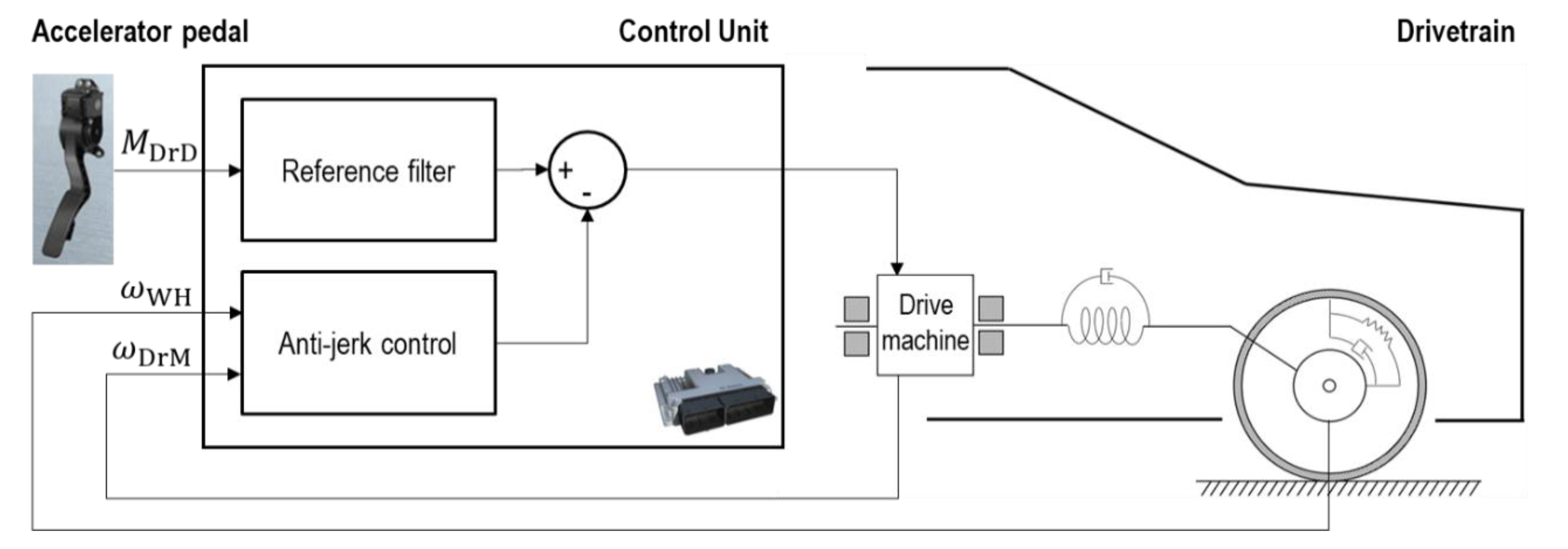
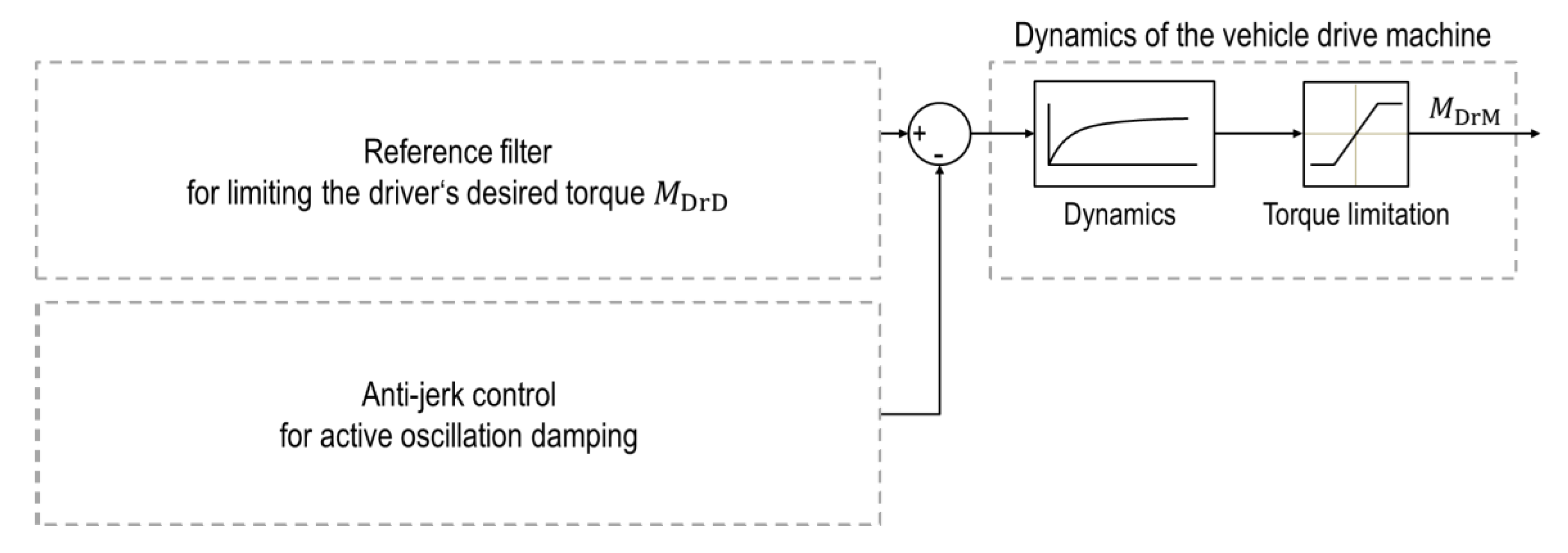
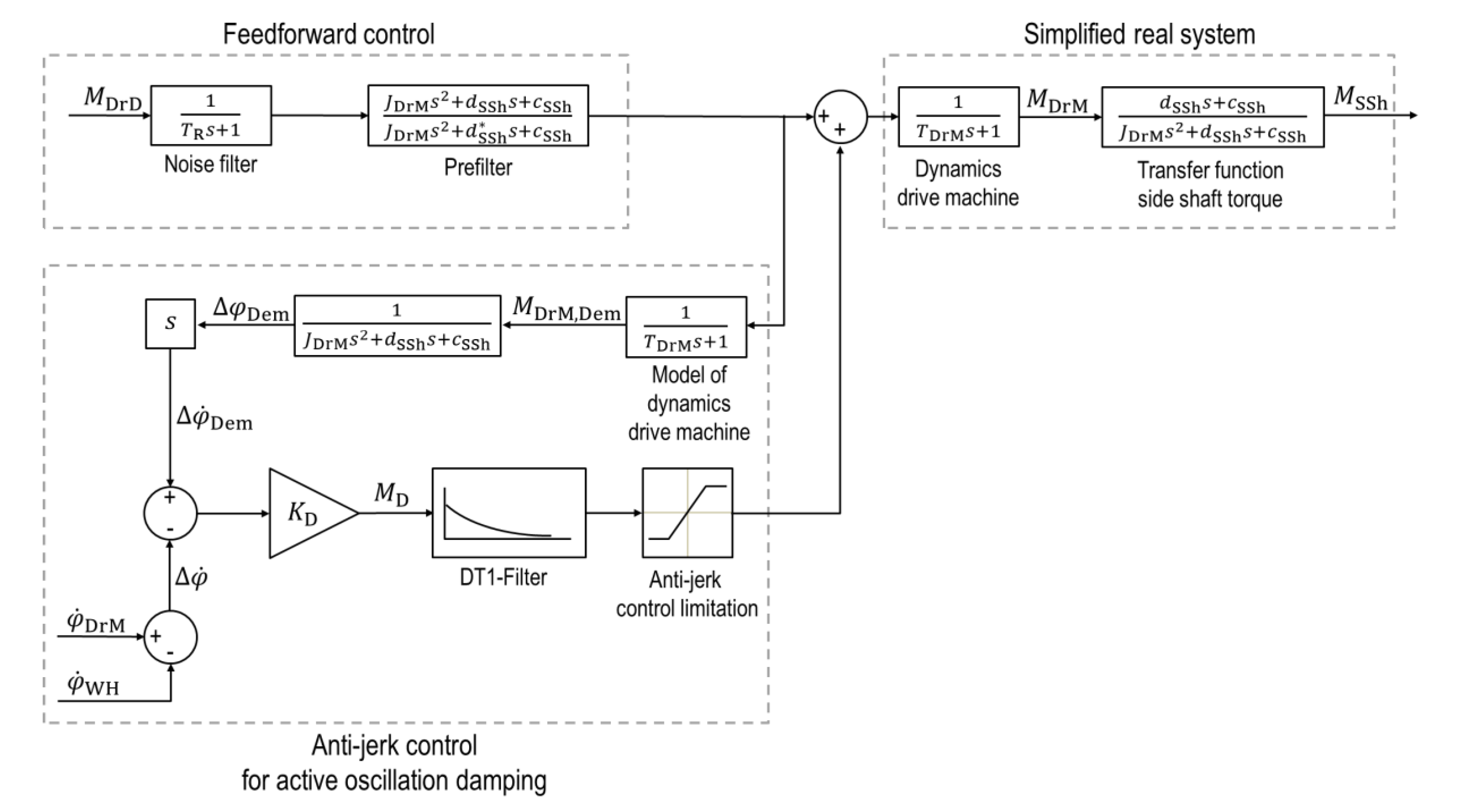
Jerk oscillations can be reduced by various approaches. For this purpose, drivability functions are implemented in the vehicle control system, which are intended to reduce the oscillation excitations and minimize occurring oscillations by means of suitable control of the drive machine(s). The drivability functions are subject to a decisive conflict of aims, which simultaneously demands the maintenance of the acceleration capacity of the vehicle as well as the avoidance of unpleasant oscillations affecting driving comfort [1]. The considered drivability function typically consists of the elements reference filter and anti-jerk control (see Figure 1).
In this paper, the driving off as well as the tip-in behavior and the resulting oscillations of an electrical single-wheel drivetrain are investigated. For oscillation damping, drivability functions are used that influence the torque of the drive machine. In this case, the main focus is an optimization of the reference filter.
An important requirement for drivability functions is an easy integration into a real vehicle. For this purpose, the required measurement signals should be easily available. Therefore, only the driver′s desired torque and the speed of the drive machine as well as the wheel are used as inputs for the algorithm. The output is the desired torque of the electric machine.
A slip model for the tire-road contact should be avoided due to its dependence on the road conditions [2,3,4].
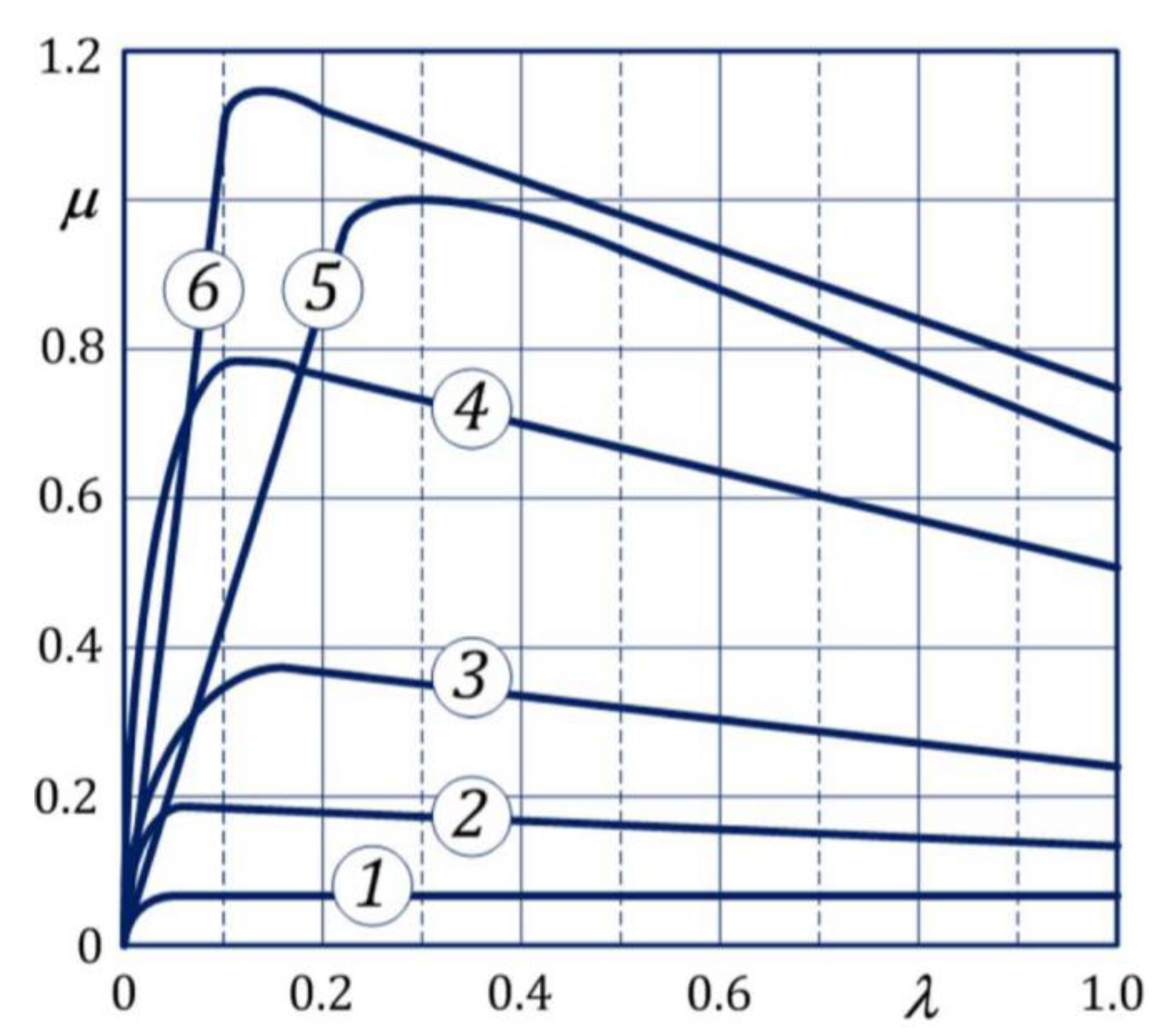
Figure 2 shows some generic tire friction-slip curves for different road conditions. These curves illustrate that the friction coefficient depends on the road conditions and the actual wheel slip .
It is further considered that the performance of the vehicle computer hardware is limited. Therefore, online optimization should be avoided. In addition, according to the explanations in [1], a simple way of monitoring for the correct functionality of the implemented algorithms in real vehicles must be ensured.
2. State of Research
For the active damping of drivetrain oscillations, several approaches exist. In [5,6,7,8,9,10], corresponding algorithms are considered and investigated by simulation and on test benches. In these cases, the oscillation damping is realized by modulating the nominal torque of the drive machine based on the difference between the rotor angular velocity of the drive machine and the equivalent vehicle angular velocity.
In [9,10] a further approach is described, consisting of the linear modelling of the drivetrain in the state space and a displacement of the pole points of the oscillation system by means of state feedback.
In addition, an observer is introduced in [5,6,9,10]. It serves for estimation of the torque applied to the wheel or the wheel speed. In this way, for example, additional sensors can be avoided.
Furthermore, in [11,12] an anti-jerking control for the first-series produced Nissan Leaf is presented. This control system is primarily demonstrated by tip-in maneuvers. The model of the electric vehicle drivetrain is described in [11]. The derived equations of motion include, for example, the vehicle mass and the coefficient of friction between tires and road surface. The described anti-jerk control consists of the parts’ feedforward and feedback compensator. The feedforward compensator is based on an inverse model of the electric vehicle; more specifically, of the transfer function from the torque of the drive machine to the angular velocity of the drive machine. This introduces a desired dynamics and means that the response can be specified by the designer. The desired dynamics is specified oscillation-free. The natural frequency of the desired transfer function acts as a design parameter.
The descriptions from [12] are based on the explanations in [11]. The transfer function of the model of the electric vehicle drivetrain is approximated.
In [13] a detailed overview of various approaches for anti-jerk control for automotive applications is given.
3. Test Environment
The functionality of the drivability functions can be demonstrated directly on the vehicle or on a hardware-in-the-loop test bench (HiL test bench). HiL test benches represent a cost-effective alternative to testing a whole vehicle on a test track and ensure reproducible results.
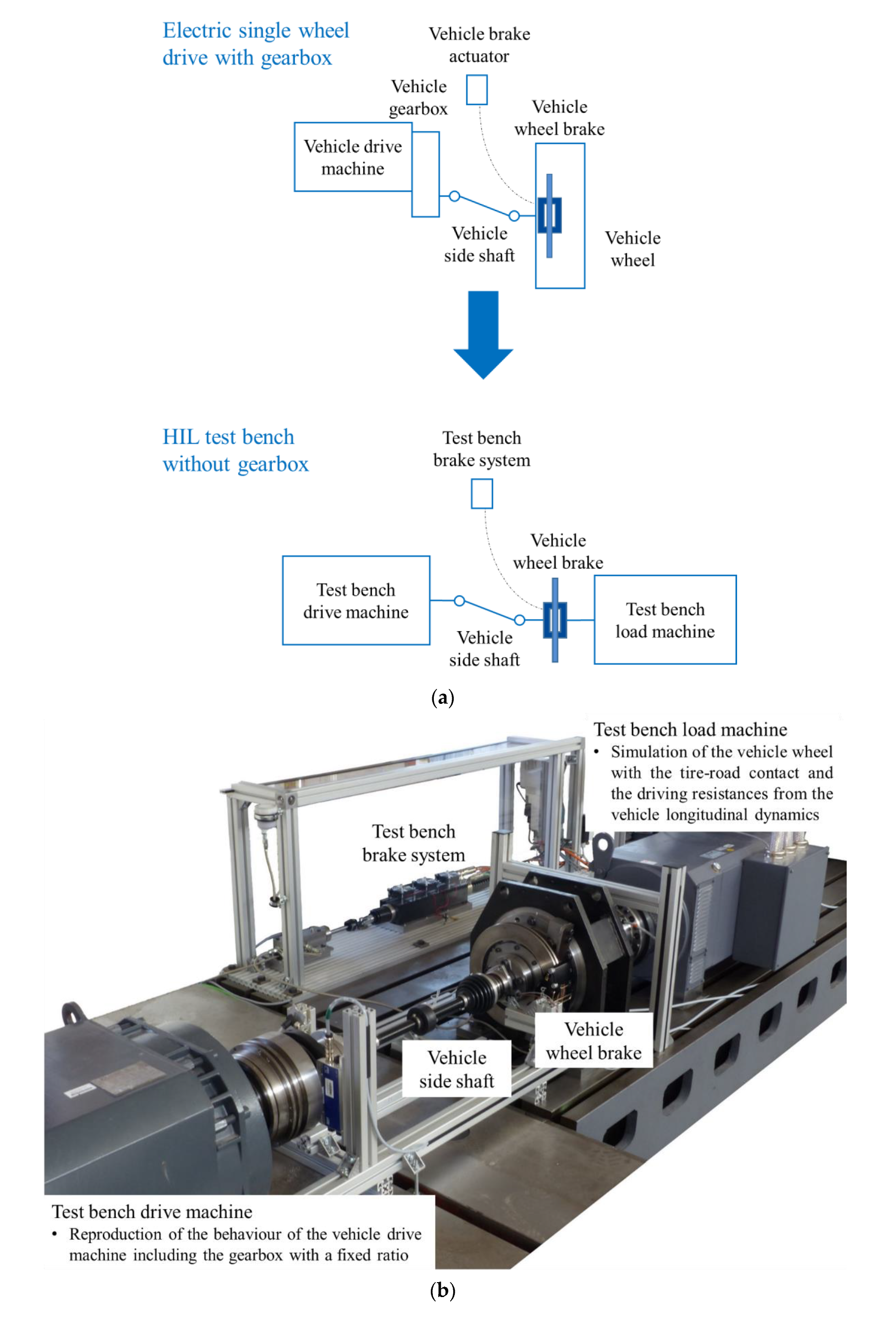
A reduction of a real single-wheel drive to the HiL test bench application is shown schematically in Figure 3a. In addition, Figure 3b shows the structure of the applied HiL test bench.
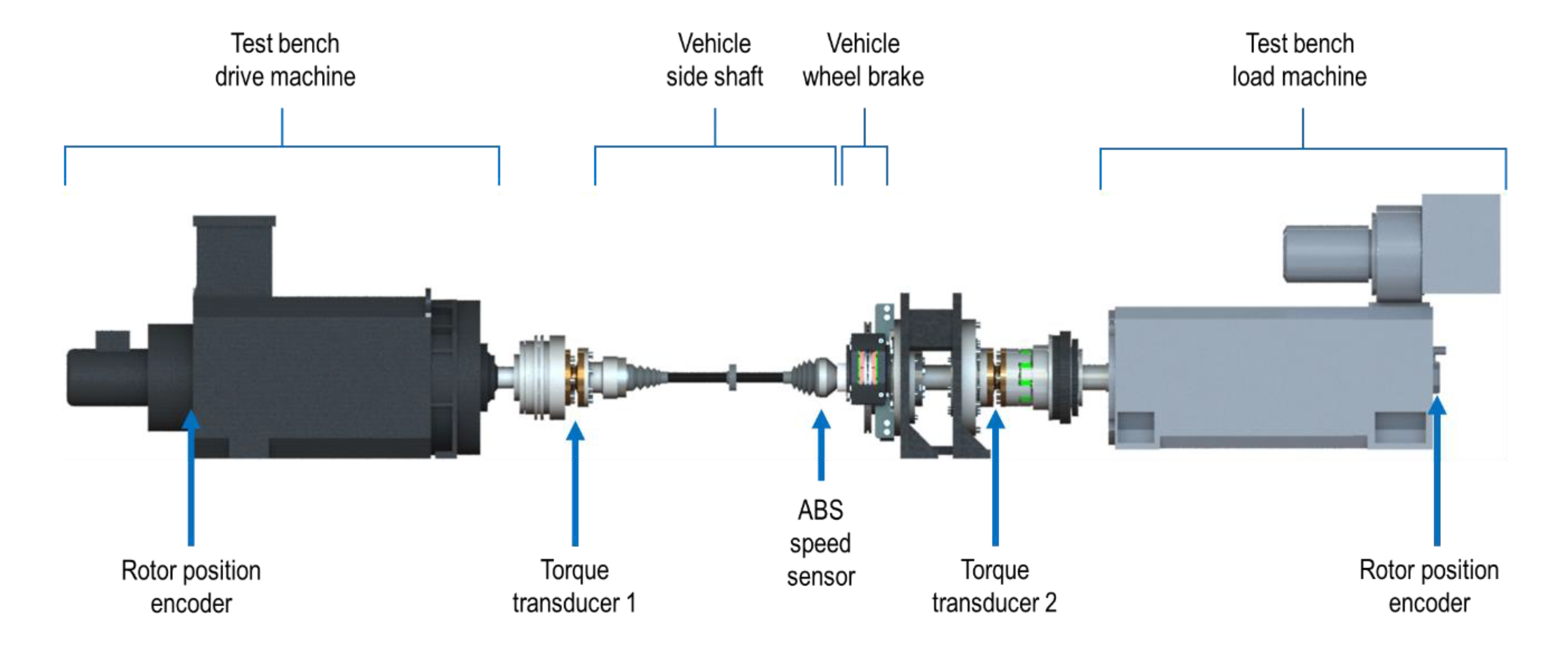
The applied HiL test bench reproduces an electric vehicle of the compact class with single-wheel drive on the front axle. The test bench drive machine reproduces the behavior of an electric vehicle drive machine including a gearbox (inertia, torque, and angular velocity related to the gearbox output shaft). A gearbox with a fixed gear ratio of 7.03 is assumed, according to the specifications in [14]. The test bench drive machine applies the driver′s desired torque modified by the investigated drivability function on the drivetrain of the HiL test bench. The test bench load machine applies the resulting torque, calculated from the simulation of the vehicle wheel with the tire-road contact and the driving resistance forces from the vehicle longitudinal dynamics (gradient, rolling, and air resistance forces), against the test bench drive machine. A suitable HiL simulation model is used for this purpose, which is described in detail in [15,16]. The reacting torques are determined by the HiL simulation model and the angular velocity at the vehicle wheel hub is reproduced by the test bench load machine. The HiL test bench also integrates a series-produced vehicle side shaft with low torsional stiffness and a vehicle-related wheel brake system [17]. The high dynamics of the HiL test bench are supported by real-time control and a network with programmable logic (FPGA) using EtherCAT communication to a test bench inverter system with 250 microseconds cycle time [15,18,19]. In addition, the HiL test bench has many high-resolution sensors, which ensure the detailed registration of torques and angular velocities (see Figure 4). Furthermore, automotive-typical sensors such as ABS speed sensors are integrated.
4. Drivability Function
Software functions are used to reduce the above-mentioned oscillations and are constantly being further developed. These are called drivability functions and, as shown in Figure 5, typically consist of a reference filter and an active anti-jerk control [1,13,21]. Both are described below.
Figure 5 also shows the typical dynamics of an electric drive machine controlled by an inverter. The dynamics are similar to a first order lag behavior with a typical time constant of . In addition, the maximum possible torques are limited. The output is the air gap torque acting on the rotor of the drive machine.
4.1. Reference Filter with Torque Gradient Limitation
As a starting point for the development of a suitable prefilter by means of inverse dynamics, the oscillation behavior with a typically used gradient limitation as a reference filter has to be considered first. The investigation of this reference filter is shown in [20].
4.1.1. Functionality of the Reference Filter
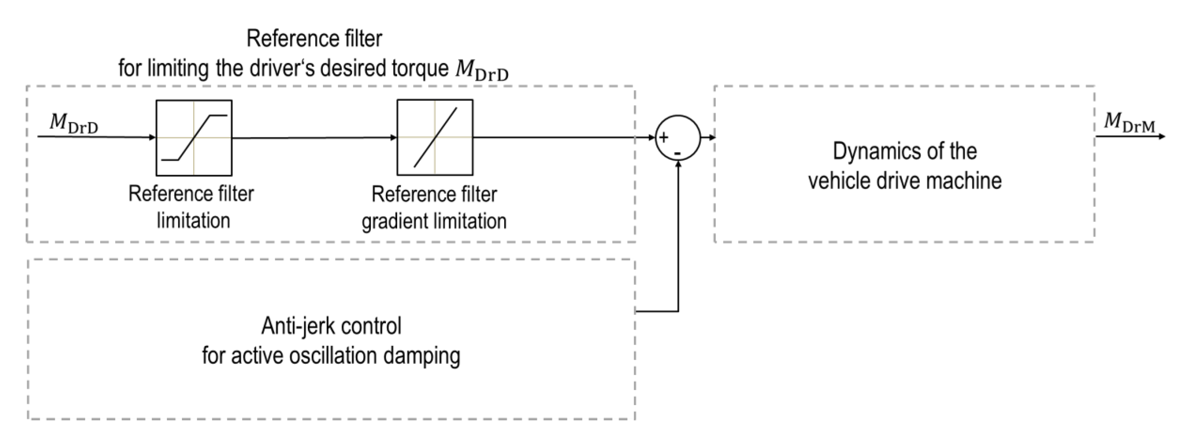
In addition to first- and second-order low-pass filters, gradient limitation is a common approach to reduce oscillations of the drivetrain by dynamic changes of the driver′s desired torque [1,13]. The gradients of the driver′s desired torque are limited, whereby the corresponding air gap torque changes more slowly (see Figure 6).
The individual components of the driveline acting as rotational springs become tensed over a longer period of time, which results in lower oscillation excitations. Changes between the tension and thrust area are filtered much more strongly than torque changes in the pure tension or thrust area [1]. A decisive conflict of interest in this point is the maintenance of the vehicle′s acceleration capacity and simultaneous the avoidance of unpleasant oscillations.
4.1.2. Measurement by Using the Reference Filter
On the described HiL test bench, driving off procedures are examined under ideal road conditions (dry asphalt, no unevenness). At the beginning of each measurement, the simulated vehicle is at standstill. At the time , a setpoint step of the driver′s desired torque is performed from to referring to the gearbox output shaft. According to the specifications in [14], a transmission ratio of is assumed. This means that a torque setpoint step at the gearbox output shaft of corresponds to one of the vehicle drive machine of approximately .
The setpoint step of the driver′s desired torque is filtered by the described reference filter during all measurements. Each measurement is parameterized with one of the three gradient limits from Table 1.
The rise time defines the time after which the desired torque of is reached at the vehicle side shaft for the first time. The overshoot shows how far the first amplitude of the vehicle side shaft torque overshoots in relation to the torque setpoint step.
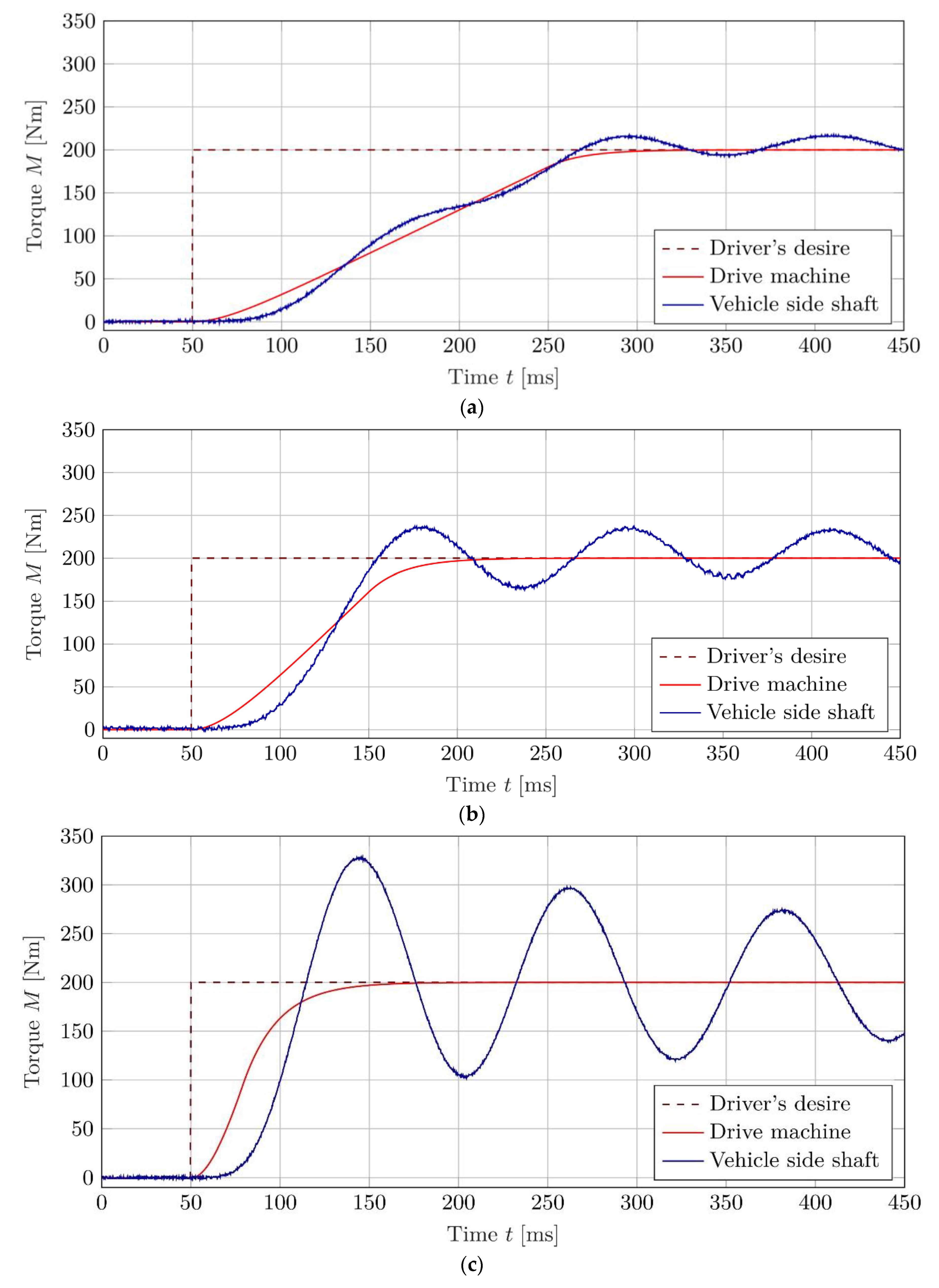
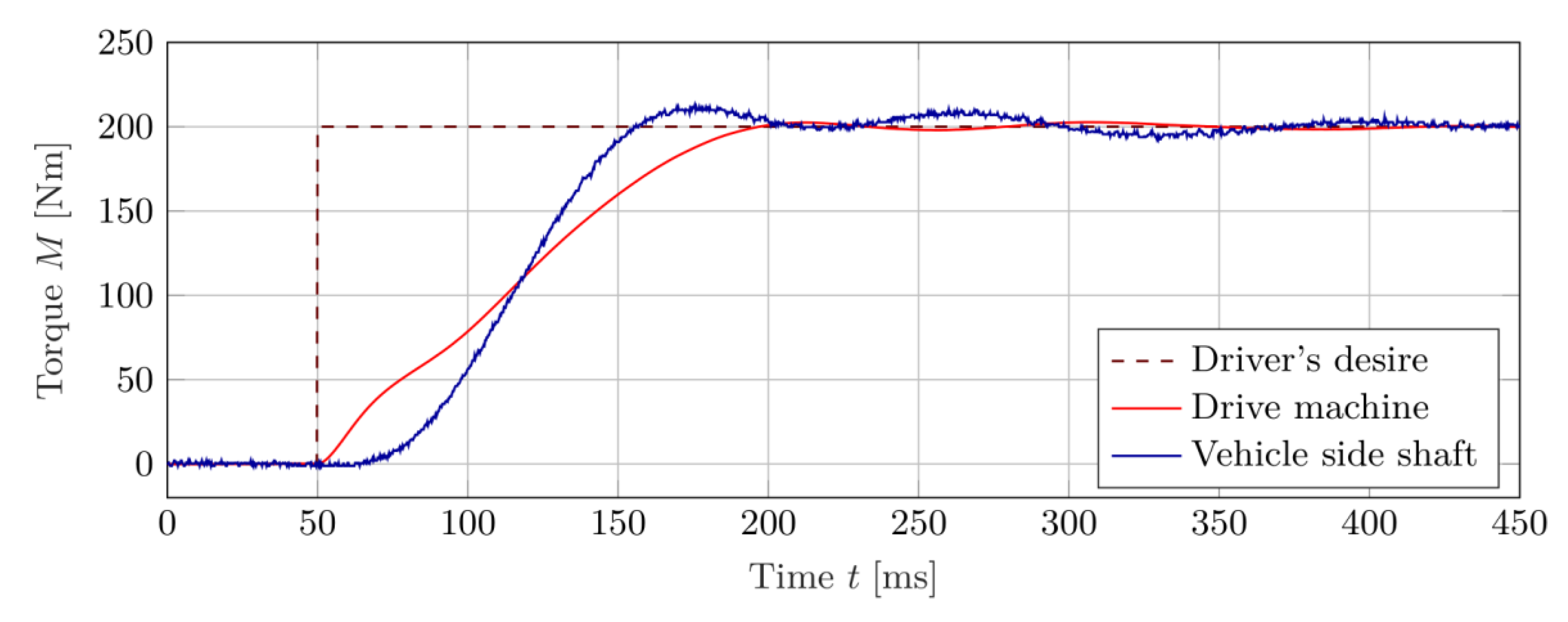
Figure 7 shows the driver′s desired torque , the air gap torque of the drive machine and the torque of the vehicle side shaft . The torque of the vehicle side shaft is measured with the torque transducer 1 (see Figure 4). The first are already sufficient to consider the different influence of the gradient limits.
In the first measurement with a gradient of for the driver′s desired torque, a delayed behavior of the air gap torque of the drive machine and the torque of the vehicle side shaft can be noticed. The torque of the vehicle side shaft oscillates only slightly in comparison to the air gap torque of the drive machine and has an overshooting amplitude of only after reaching the setpoint for the first time. Due to the low gradient limitation of the driver′s desire torque, the torque build-up on the vehicle side shaft is comparatively slow; the torque of is reached after . The oscillation amplitudes are afterwards below of the setpoint.
The second measurement with a gradient of shows a significant difference compared to the first measurement. At first, a constantly increasing torque of the vehicle side shaft can be detected without oscillation around the air gap torque of the drive machine. The vehicle side shaft is more tensioned and causes a larger overshooting amplitude. This overshooting amplitude of nearly is higher in comparison to the first measurement. Because of the higher gradient, the torque of is already reached after in this measurement but continues to oscillate for a longer time with an amplitude of more than of the setpoint.
The third measurement with a gradient of does not strongly differ from the second measurement. A constantly increasing torque of the vehicle side shaft without oscillation around the air gap torque of the drive machine can also be detected. The torque of the vehicle side shaft has an overshooting amplitude of after reaching the setpoint and is therefore more than 1.5 times higher than the setpoint. Because of the higher gradient, the torque of is reached after but oscillates more strongly.
A further increase in the gradient of the driver′s desired torque is no longer useful for a setpoint step of . The drive machine dynamics limits the gradient more than the reference filter does.
The measurements demonstrate clearly the mentioned conflict of aims in the development of suitable algorithms for reference filters. High dynamics in the control of the drive machine leads to strong oscillation excitation caused by the low torsional stiffness of the vehicle side shaft. However, a significant reduction of these oscillations by limiting the gradients leads to an unacceptable loss of vehicle dynamics.
4.2. Anti-Jerk Control
Another approach for active damping of jerk oscillations is an anti-jerk control. This also compensates disturbances that are not compensated by the reference filter. Examples for such disturbances are backlash in the gearbox, brake interferences, road unevenness, modelling errors, and other factors.
The anti-jerk control typically relies on the feedback of various angular velocity as well as torque signals to modify the demand torque of the drive machine. Additionally, in several approaches, the longitudinal vehicle acceleration is taken into account. In addition to the references mentioned in Section 2, in [13] a detailed review of various anti-jerk controllers for automotive applications is given. A detailed description of the anti-jerk control used in this research is presented in Section 6.
The following investigations focus on the optimization of the reference filter. The interaction of the further developed reference filter and the anti-jerk control is finally demonstrated. A reduction of the oscillation by an optimal reference filter relieves the anti-jerk control.
5. Prefilter Using Inverse Dynamics
A prefilter is a commonly used procedure for improving the reference behavior. For this purpose, the prefilter implements a corresponding influence on the setpoint. This allows for compensation of the poles of the reference transfer function partially or completely [22,23]. In addition, according to [24], the reference behavior can be independently adjusted within certain limits by means of prefilters. Oscillations excited by the reference value can be reduced by selecting a suitable filter transfer function with appropriate parameter selection. For physical systems, this can be realized by inverting the dynamic system behavior.
5.1. Prefilter Design
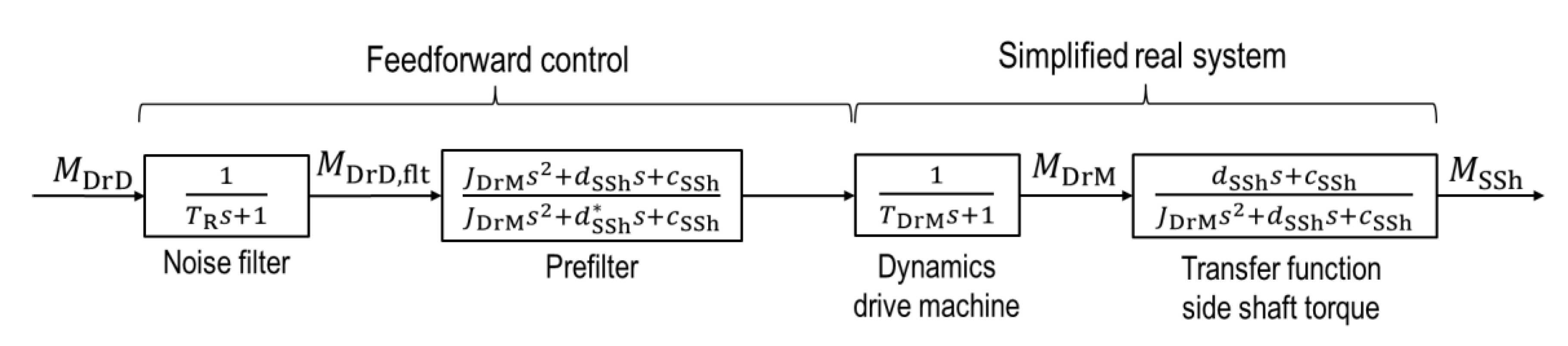
According to the explanations in [24], the first step is to consider the elastic, electrified vehicle drive system (see Figure 8). The dynamics for the air gap torque of the drive machine , the moment of inertia of the drive machine as well as the torsional stiffness and torsional damping of the vehicle side shaft are taken into account. Furthermore, for an optimal design and parameterization of the prefilter, a good knowledge of the system properties that characterize the transfer behavior is necessary.
The prefilter should reduce the vehicle side shaft oscillations during load changes. However, the dynamics of the vehicle should be maintained as far as possible.
In order to ensure the requirements in Section 1, the vehicle wheel hub is defined as the system boundary. This system boundary eliminates a necessary determination of the tire–road contact and the vehicle longitudinal dynamics. Observers and estimation methods for, e.g., the vehicle mass , vehicle speed, the vertical wheel contact forces, the friction coefficient of the tire , and other parameters, especially for different road conditions, can be avoided. Further, the parameterization effort for the prefilter for different vehicle types and configurations can be reduced. Additionally, there is no more need to consider the moments of inertia of the wheel hub and the tire belt , the dynamic behavior of the rotation angle of the tire belt and the dynamic tire radius . Additionally, the torsional stiffness and the torsional damping of the tire sidewall, which both depend on many factors, are not required.
Furthermore, ABS speed sensors are fitted as standard in all modern vehicles directly on the vehicle wheel hub. This makes it possible to measure the angular velocity or the rotation angle of the vehicle wheel hub. Likewise, the electric machines typically used are equipped with corresponding sensors to measure the angular velocity or the rotation angle The driver’s desired torque is used as the input to the prefilter. This value is typically detected using potentiometers on the accelerator pedal. A first order lag filter with a time constant is used to reduce the noise of the analogue signal representing the actuation of the accelerator pedal.
For the determination of the prefilter, the motion differential equations of the reduced drive system are set up in the form of
Conversion and Laplace transformation of the two equations lead to the form
By inserting the Equation (3) for the rotation angle of the drive machine into the Equation (4) with subsequent forming, the transfer function for the torque of the vehicle side shaft can be determined to
The Equation (5) shows that the torque of the vehicle side shaft , in addition to the air gap torque of the drive machine, , depends on the angular acceleration of the wheel hub . In principle, it is possible to compensate the right term in Equation (5) at least partially, for example by a dependence of the air gap torque on the measured angular acceleration of the wheel hub . Especially at low angular velocity of the wheel hub the measurement of the angular acceleration is quite difficult [2,16,25]. The main reason for this is the typical encoder resolution of the ABS speed sensors of present vehicles. At a low angular velocity of the wheel hub the typical encoder resolution leads to high noisy signal for the angular acceleration . Therefore, and due to its minor influence on the system behavior, the term dependent on the angular acceleration in Equation (5) is neglected. In the following, driving off and tip-in maneuvers are examined to show this approach.
The used, simplified transfer function results in
This equation, together with the dynamics of the drive machine, forms the simplified model of the real system. The dynamics can be assumed as a first order lag element with the time constant as described in Section 4. The torque limitation is not considered here.
The prefilter can now be derived from the simplified system model conforming to Equation (6). According to the explanations in [22,24], the poles of the stable real system are to be compensated by the transfer function of the prefilter. Therefore, the prefilter includes a pair of zeros, which eliminates the underdamped poles of the real system.
The selected transfer function of the prefilter is calculated in the form
It is suggested to choose the parameters of the prefilter of Equation (7) according to the real physical parameters of the drive system. Only the damping constant is significantly increased compared to the real system. This increases the damping ratio of the poles added by the prefilter. As a result, the desired transfer function is close to that of the simplified real system. This keeps the dynamics of the required air gap torque at a low level. Thus, the dynamic loads of the electric system are kept minimal and less problems with limitations of control variables occur.
The damping constant represents a design parameter for the trade-off between the comfort level and the acceleration capacity. For a very high comfort level the first acceleration peak during tip-ins should be completely damped, as presented in [12] and suggest by [26,27]. In contrast, for a sports-oriented vehicle behavior, a lightly damped first peak with absence of subsequent oscillation is preferable [27]. In this research, the damping constant is designed to achieve a damping ratio of the torque of the vehicle side shaft of 0.76 and corresponds to other known approaches [13]. However, it is possible to adjust the damping constant during operation of the vehicle to various driving modes (comfort, sport, eco, etc.).
5.2. Measurement by Using the Designed Prefilter
The measuring sequence for driving off procedure is identical to the measurement with the gradient limitation as reference filter (see Section 4.1.2). At the beginning of each measurement, the simulated vehicle is at standstill. At time , a setpoint step of the driver’s desired torque from to related to the gearbox output shaft takes place, which corresponds to a step in the setpoint of the vehicle drive machine of approximately .
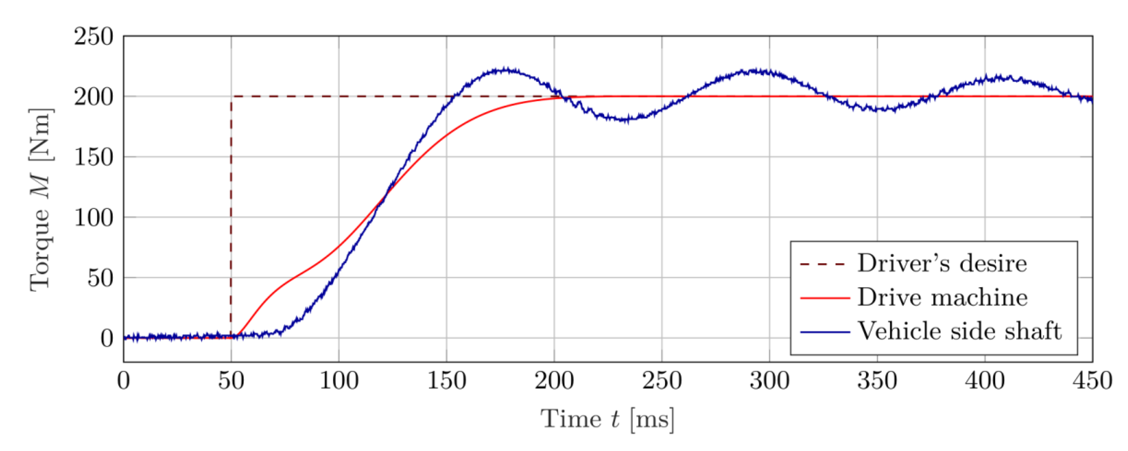
Figure 11 shows a modified sequence behavior of the air gap torque of the drive machine and the torque of the vehicle side shaft. The torque of the vehicle side shaft is measured again with the torque transducer 1 (see Figure 4).
The torque of the vehicle side shaft shows no oscillations during torque build-up. In comparison to the measurement with a gradient limitation of as reference filter (Figure 7b) the driver’s desired torque is also reached after , but only a slight overshoot occurs in the side shaft torque. This overshoot is already within the tolerance of of the driver’s desired torque. The oscillation is slightly damped, so that the oscillation amplitude decreases only slowly. In comparison to the measurements shown in Figure 7 with gradient limitation as reference filter, the oscillations in the side shaft torque are considerably reduced with acceptable vehicle dynamics.
In Figure 11, the air gap torque is adjusted at time , and then runs with slightly smaller gradients. Thus, the side shaft is not strongly tensed and the overshoot is reduced.
The prefilter only acts on the driver’s desired torque. After it is reached, the air gap torque remains constant. The lag of control of the oscillations causes the natural oscillation behavior of the drivetrain to show up with a frequency of approximately in the side shaft torque. This behavior also reflects an oscillation excitation by the road or the wheel brake, which would not be compensated by the prefilter. Corresponding interferences as well as parameter inaccuracies and model uncertainties must therefore be compensated by an additional anti-jerk control [28,29].
In addition to the driving off procedure above and in comparison to [11] it is useful to look at the behavior of the drivetrain while tip-in procedures. Therefore, the test conditions are the same as in the measurements before.
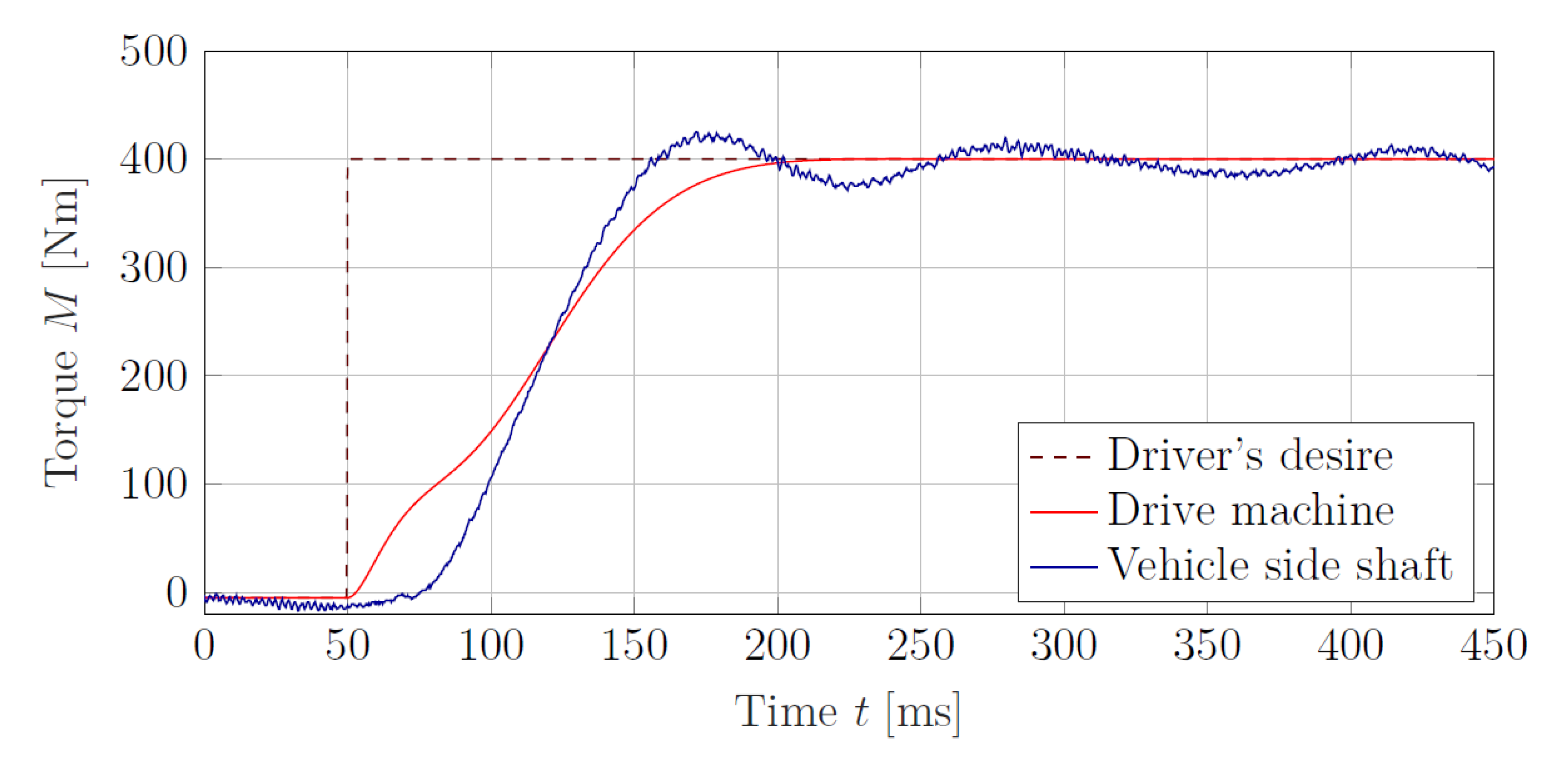
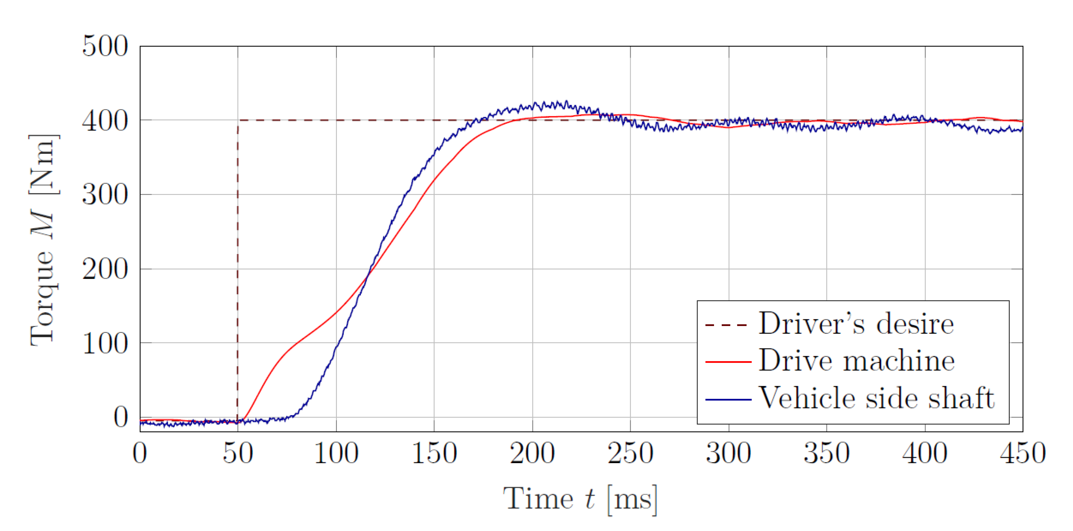
The examination is performed under ideal road conditions (dry asphalt, no unevenness). At the beginning of each measurement, the simulated vehicle runs down to . At the time , a setpoint step of the driver′s desired torque is performed from to , referring to the gearbox output shaft of a single wheel drive. With the before-mentioned transmission ratio of the torque setpoint step at the gearbox output shaft to corresponds to one of the vehicle drive machine of approximately .
Figure 12 shows the driver′s desired torque referring to the gearbox output shaft of a single wheel drive, the air gap torque of the drive machine and the vehicle side shaft torque measured with the torque transducer 1. The behavior of the air gap torque of the drive machine and the torque of the vehicle side shaft is similar in comparison to Figure 11.
The torque of the vehicle side shaft shows no oscillations during torque build-up. In comparison to the measurement at standstill the driver’s desired torque is also reached after , with a reduced overshoot in the side shaft torque. This overshoot is within a tolerance of of the driver’s desired torque. The oscillation is slightly damped and the oscillation amplitude decreases only slowly.
The measurements in [11] present a similar tip-in driving test with an experimental electrical vehicle. In [11], the first oscillation touches the setpoint step within a range of 10% at the time after the setpoint step and oscillates afterwards near the setpoint step.
The motor torque in [11] shows a torque peak shortly after the setpoint step with approximately 90% of the setpoint step and is then reduced to approximately 40%. The setpoint is reached after approximately .
Figure 12 shows slighter adjustments with a monotonically increased torque build-up and no decrease. After approximately the torque of the drive machine reaches the setpoint without oscillation.
6. Prefilter Using Inverse Dynamics and Anti-Jerk Control
Finally, the designed reference filter is supplemented by an anti-jerk control. In addition to the adjustment of the driver’s desired torque, a filtered and limited correction torque is also applied.
6.1. Anti-Jerk Control Design
The applied anti-jerk control is based on the algorithm described in [15,16]. This algorithm was already used, among other things, to investigate the influence of low-resolution rotor position encoders on the drivability functions [16]. Additionally, the use of the designed reference filter enables a modification of this anti-jerk control algorithm.
For the anti-jerk control, in a first step the angular velocities of the vehicle drive machine (related to the gearbox output shaft) and the vehicle wheel hub are compared with each other in accordance to [15,16]. This results in a differential angular velocity . In modification to the descriptions in [15,16] this differential angular velocity is compared with a demand differential angular velocity . The demand differential angular velocity is determined from the system model of the prefilter, as shown in Figure 13.
The differential angle of the side shaft is defined as
Using the transfer function of the side shaft (Equation (4)) this differential angle can be calculated by
Furthermore, from Equations (6) and (9) the differential angle in dependence of the torque of the vehicle drive machine can be represented in the form
Finally, with Equation (10), a model for the dynamics of the vehicle drive machine as well as a derivative, the above described demand differential angular velocity can be determined (see Figure 13).
Any variations using a positive gain factor result in a corresponding damping torque in form of
The gain factor can be interpreted as an equivalent to a viscous damping constant of the drivetrain. The damping torque is calculated by using a derivative element with first order lag filter and a torque limiter. This torque is added to the driver′s desired torque modified by the reference filter. The result represents the demand torque of the vehicle drive machine (see Figure 13).
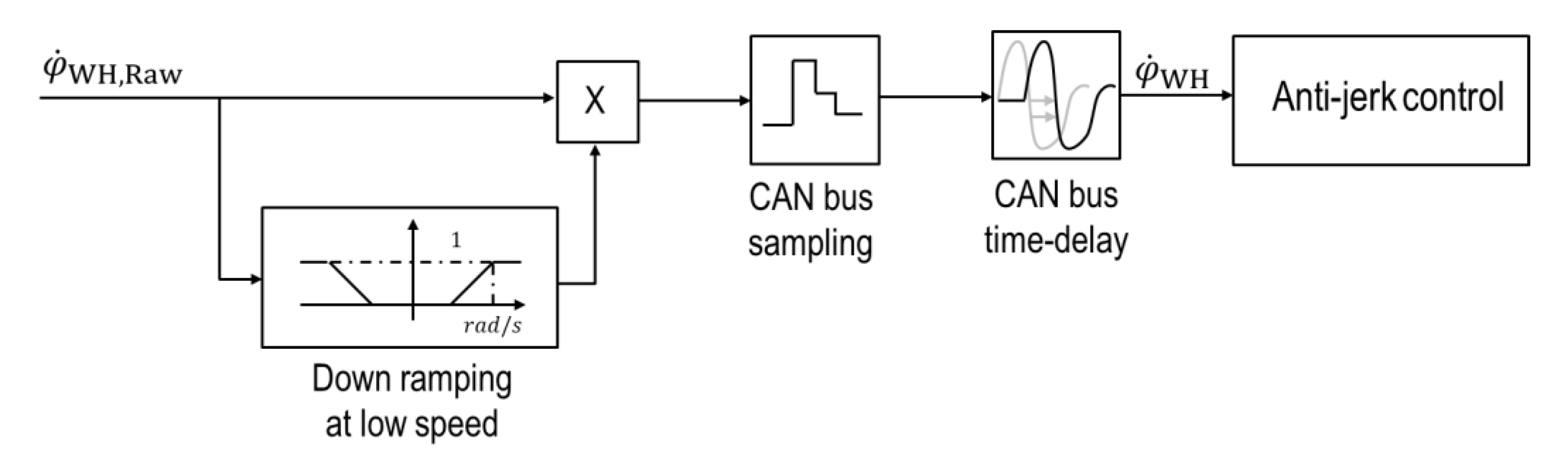
In contrast to the descriptions in [11,12], the angular velocity of the vehicle wheel hub detected by an ABS speed sensor is used here. In vehicles, the signals of the ABS speed sensors are typically transmitted via a CAN bus network. For the investigations an ABS speed sensor of a real vehicle is integrated in the HiL test bench (see Figure 4). The ABS speed sensor is evaluated by the FPGA of the HiL test bench. According to the descriptions in [10], the raw value of the angular velocity of the vehicle wheel hub is ramped down at low values. Further, the CAN bus network is emulated via a sample rate of and an additionally time-delay of is applied (see Figure 14).
Compared to the explanations in [11,12], the dynamics of the drive machine are taken into account here. Furthermore, the designed algorithms for the prefilter and the anti-jerk control do not contain varying vehicle parameters, such as the vehicle mass and the tire–road contact. However, the measured angular velocity of the vehicle wheel hub is required here.
For optimization, it is advised to adjust not only the damping constant of the prefilter but also the gain factor of the anti-jerk control to the various driving modes (comfort, sport, eco, etc.).
The effectiveness of this prefilter in combination with the anti-jerk control is again verified with the HiL test bench.
6.2. Measurement by Using the Designed Prefilter and the Anti-Jerk Control
The measuring sequence for a driving off procedure is identical to the measurement with the gradient limitation as reference filter (see Section 4.1.2) and the designed prefilter (see Section 5.2). At the beginning of each measurement, the simulated vehicle is at standstill. At time , a setpoint step of the driver’s desired torque from to related to the gearbox output shaft takes place, which corresponds to a step in the setpoint of the vehicle drive machine of approximately .
Figure 15 shows a modified sequence behavior of the air gap torque of the drive machine and the torque of the vehicle side shaft. The torque of the vehicle side shaft is measured again with the torque transducer 1 (see Figure 4). The angular velocity of the vehicle wheel hub , which is required for the anti-jerk control, is detected with an ABS speed sensor. The time-delay of a CAN bus network is simulated as described in Section 6.1.
A further reduction of the occurring torsional oscillation can be seen in the curves of the measured torque of the vehicle side shaft (see Figure 15). The side shaft torque builds-up as before, without oscillation, within approximately , but again exceeds the required driver’s desired torque. The overshooting amplitude of the side shaft torque with active anti-jerk control is about. This overshoot is within the tolerance of of the driver’s desired torque and decreases over the time. The system is more damped compared to Figure 11.
The influence of the anti-jerk control can be seen in the air gap torque of the drive machine. In comparison to Figure 11, the air gap torque is restored at time with slightly smaller gradients. Thus, the side shaft is not strongly tensed and the overshoot is reduced. In Figure 15, the air gap torque does not remain constant as in Figure 11, but counteracts the oscillations of the side shaft torque. This ensures a faster reduction of the oscillation amplitudes, which at the end of the time window oscillate only approximately to each side around the driver’s desired torque.
Again in addition to the driving off procedure above, and in comparison to [11], tip-in procedures are examined. The test conditions are the same as in the measurements before.
At the beginning of each measurement, the simulated vehicle is at . At the time , a setpoint step of the driver′s desired torque is performed from to referring to the gearbox output shaft of a single wheel drive. With the before mentioned transmission ratio of the torque setpoint step at the gearbox output shaft to corresponds to one of the vehicle drive machine of approximately .
Figure 16 shows again the driver′s desired torque, referring to the gearbox output shaft of a single wheel drive, the air gap torque of the drive machine and the torque of the vehicle side shaft, which is measured with the torque transducer 1. The required angular velocity of the vehicle wheel hub is detected again with the integrated ABS speed sensor.
The torque of the vehicle side shaft shows no oscillations during torque build-up. The driver’s desired torque is reached at after the setpoint step. The overshoot in the torque of the vehicle side shaft is within a range of approximately . The oscillation is well damped.
Again, a similar tip-in driving test with an experimental electrical vehicle is presented in [11]. In comparison to Figure 16, the overshoot in the torque of the vehicle side shaft is slightly lower in [11]. In addition, the setpoint in [11] is reached faster.
In [11], the build-up of the motor torque again shows a torque peak shortly after the setpoint step with approximately 90% of the setpoint step and a reduction to approximately 40%. In contrast, the torque build-up of the drive machine in Figure 16 shows no torque peak, as well as a slighter adjustment with a monotonic increase and no decrease. By avoiding this torque peak, the dynamic load of the electric system, for example, is reduced.
7. Summary and Outlook
This article shows the problem of oscillation excitation in electrical single-wheel drivetrains of vehicles and suggests a possible solution. A developed reference filter for the reduction of drivetrain oscillations provides an optimization in the conflict between driving comfort and acceleration capacity of the vehicle. An additional anti-jerk control approach improves the results and reduces jerk oscillations even further.
The development of this reference filter is based on driving off and tip-in investigations of the drivetrain on a HiL test bench with a setpoint step of the driver′s desired torque. For this purpose, a reference filter with gradient limitation is used for comparing. A typically used additional anti-jerk control in the drivability function is not used for the comparative measurements.
By implementing a prefilter using the inverse dynamics of the drivetrain, the drivetrain oscillations can already be reduced considerably. However, by coupling the prefilter to the driver′s desired torque alone, it is not possible to react to excitations from the road or the vehicle wheel brake.
The addition of an anti-jerk control to the prefilter solves this problem and enhances the responsiveness to excitations from the road or the vehicle wheel brake. The anti-jerk control also effectively compensates excited oscillations after the driver′s desired torque has been reached.
For further development of the prefilter, an implementation of the nonlinearity of the torsional stiffness and the torsional damping of the vehicle side shaft is planned.
In addition, investigations on the influence of different resolutions of vehicle-related encoders on the presented algorithms are also in focus. With the existing brake system, the operating points with brake intervention will then be investigated with regard to drivetrain oscillations, their detection and their active damping.
Author Contributions
Conceptualization, A.K. and J.F.; methodology, A.K. and L.S.; software, A.K. and L.S.; validation, A.K., L.S. and G.J.; investigation, A.K. and L.S.; resources, J.F.; writing—original draft preparation, A.K., L.S., G.J. and J.F.; writing—review and editing, A.K., L.S., G.J. and J.F.; visualization, G.J. and A.K.; project administration, J.F. and A.K. All authors have read and agreed to the published version of the manuscript.
Funding
This research received no external funding.
Conflicts of Interest
The authors declare no conflict of interest.
References
- Reif, K. Automobilelektronik; 4. Aufl.; Vieweg + Teubner Verlag: Wiesbaden, Germany, 2012; ISBN 978-3-8348-1498-2. [Google Scholar]
- Burkhardt, M. Fahrwerktechnik: Radschlupf-Regelsysteme; 1 Aufl.; Vogel Verlag: Würzburg, Germany, 1993; ISBN 3-8023-0477-2. [Google Scholar]
- Reif, K. Brakes, Brake Control and Driver Assistance Systems: Function, Regulation and Components; Springer Vieweg GmbH: Wiesbaden, Germany, 2014. [Google Scholar] [CrossRef]
- Ivanov, V.; Savitski, D.; Shyrokau, B. A Survey of Traction Control and Antilock Braking Systems of Full Electric Vehicles with Individually Controlled Electric Motors; IEEE Transactions on Vehicular Technology: Sendai, Japan, 2015; Volume 64. [Google Scholar] [CrossRef]
- Amann, N.; Bocker, J.; Prenner, F. Active damping of drive train oscillations for an electrically driven vehicle. IEEE/ASME Trans. Mechatron. 2004, 9. [Google Scholar] [CrossRef]
- Götting, G.; De Doncker, R.W. Active drive control of electric vehicles using a modal state observer. In Proceedings of the 2004 IEEE 35th Annual Power Electronics Specialists Conference (IEEE Cat. No.04CH37551), Aachen, Germany, 20–25 June 2004. [Google Scholar]
- Orus, J.; Theunissen, J.; Meneses, R.; Rodriguez-Fortun, J.-M. Active vibration control for torsional oscillations in powertrains for fully electric vehicles. In F2014-Special Session ‘Vehicle Dynamics Control for Fully Electric Vehicles—Outcomes of the European Project E-VECTOORC; Flanders’ Drive Belgium: Lommel, Belgium, 2014. [Google Scholar]
- Menne, M. Drehschwingungen im Antriebsstrang von Elektrostraßenfahrzeugen–Analyse und aktive Dämpfung; Wissenschaftsverlag Mainz: Mainz, Germany, 2001; ISBN 3-86073-684-1. [Google Scholar]
- Rodríguez, J.-M.; Meneses, R.; Orús, J. Active vibration control for electric vehicle compliant drivetrains. In Proceedings of the IECON 2013—39th Annual Conference of the IEEE Industrial Electronics Society, Vienna, Austria, 10–13 November 2013. [Google Scholar] [CrossRef]
- Zhao, S.; Lasson, A.; Wallmark, O.; Leksell, M. Off-Vehicle Evaluation of Active Oscillation Damping Schemes. IEEE J. Emerg. Sel. Top. Power Electron. 2014, 2. [Google Scholar] [CrossRef]
- Karikomi, T.; Itou, K.; Okubo, T.; Fujimoto, S. Development of the shaking vibration control for electric vehicles. In Proceedings of the 2006 SICE-ICASE International Joint Conference, Busan, Korea, 18–21 October 2006. [Google Scholar] [CrossRef]
- Kawamura, H.; Ito, K.; Karikomi, T.; Kume, T. Highly-responsive acceleration control for the Nissan LEAF electric vehicle. SAE Tech. Pap. 2011. [Google Scholar] [CrossRef]
- Scamarcio, A.; Gruber, P.; De Pinto, S.; Sorniotti, A. Anti-jerk controllers for automotive applications: A review. Annu. Rev. Control. 2020. [Google Scholar] [CrossRef]
- Rosenberger, M. Audi Dissertationsreihe. Bd. 89: Regelung Radnaher Elektrischer Einzelradantriebe Während der ABS-Bremsung; Cuvillier Verlag: Göttingen, Germany, 2014; ISBN 978-3-95404-655-3. [Google Scholar]
- Koch, A. Entwicklung eines Hardware-In-The-Loop-Prüfstandes zur Untersuchung der Drehschwingungen und Bremssystemkoordination bei Einzelradantrieben von Elektrofahrzeugen; Verlag: Dr. Hut: München, Germany, 2018; ISBN 978-3-8439-3750-4. [Google Scholar]
- Koch, A.; Schulz, L.; Jakstas, G.; Falkenstein, J. Untersuchung und Optimierung des Einflusses von niedrig auflösenden Rotorlagegebern auf die Fahrbarkeitsfunktionen elektrifizierter Fahrzeugantriebssysteme mittels eines Hardware-in-the-Loop-Prüfstands. In Forschung im Ingenieurwesen; Springer Nature: Heidelberg, Germany, 2020. [Google Scholar] [CrossRef] [Green Version]
- Koch, A.; Jakstas, G.; Falkenstein, J. Elektrohydraulischer Bremsaktuator zur Nachbildung von Fahrzeug-Bremssystemen; antriebstechnik 11/2017; Vereinigte Fachverlage GmbH: Mainz, Germany, 2017; pp. 136–145. [Google Scholar]
- Beckhoff Automation GmbH. EtherCAT System-Dokumentation; Version: 5.1; Beckhoff Automation GmbH.: Verl, Germany, 2016. [Google Scholar]
- Nidec Control Techniques Ltd. User Guide: Unidrive M700/M701/M702; Version: 2.0; Nidec Control Techniques Ltd.: Newtown, UK, 2018. [Google Scholar]
- Jakstas, G.; Schulz, L.; Koch, A.; Falkenstein, J.; Gössner, S. 13. Kolloquium Getriebetechnik: Untersuchung und Optimierung des Anfahrverhaltens bei Elektrifizierten Fahrzeugantriebssystemen Mittels Hardware-In-The-Loop-Prüfstand; Logos Verlag Berlin: Berlin, Germany, 2019; ISBN 978-3-8325-4979-4. [Google Scholar]
- Götting, G. Dynamische Antriebsregelung von Elektrostraßenfahrzeugen unter Berücksichtigung eines Schwingungsfähigen Antriebsstrangs; Shaker Verlag GmbH: Herzogenrath, Germany, 2004; ISBN 978-3-8322-2804-0. [Google Scholar]
- Unbehauen, H. Regelungstechnik 1: Klassische Verfahren zur Analyse und Synthese Linearer kontinuierlicher Regelsysteme, Fuzzy-Regelsysteme; 15. Auflage; Vieweg + Teubner Verlag: Wiesbaden, Germany, 2008; ISBN 978-3-8348-0497-6. [Google Scholar]
- Unbehauen, H.; Ley, F. Das Ingenieurwissen: Regelungs- und Steuerungstechnik; Springer GmbH: Berlin/Heidelberg, Germany, 2014. [Google Scholar] [CrossRef]
- Janschek, K. Systementwurf Mechatronischer Systeme: Methoden–Modelle–Konzepte; Springer GmbH: Berlin/Heidelberg, Germany, 2010. [Google Scholar] [CrossRef]
- Reif, K. Bosch Autoelektrik und Autoelektronik: Bordnetze, Sensoren und Elektronische Systeme; 6. Aufl.; Vieweg + Teubner Verlag: Wiesbaden, Germany; Springer Fachmedien Wiesbaden GmbH: Wiesbaden, Germany, 2011; ISBN 978-3-8348-1274-2. [Google Scholar]
- Berriri, M.; Chevrel, P.; Lefebvre, D. Active damping of automotive powertrain oscillations by a partial torque compensator. Control Eng. Pract. 2008, 16. [Google Scholar] [CrossRef]
- Grotjahn, M.; Quernheim, L.; Zemke, S. Modelling and identification of car driveline dynamics for anti-jerk controller design. IEEE Int. Conf. Mechatron. 2006. [Google Scholar] [CrossRef]
- Lunze, J. Regelungstechnik 2: Mehrgrößensysteme, Digitale Regelung; 3. Auflage; Springer GmbH: Berlin/Heidelberg, Germany, 2005; ISBN 3-540-22177-8. [Google Scholar]
- Lunze, J. Regelungstechnik 1: Systemtheoretische Grundlagen, Analyse und Entwurf einschleifiger Regelungen; 11. Auflage; Springer GmbH: Berlin/Heidelberg, Germany, 2016. [Google Scholar] [CrossRef]
Figure 1.
Overview of the drivability function.

Figure 2.
Generic tire friction-slip curves. 1–glaze ice; 2–snow; 3–wet cobbled roadway; 4–wet worn-out asphalt; 5–dry cobbled roadway; 6–dry asphalt. [4].
Figure 2.
Generic tire friction-slip curves. 1–glaze ice; 2–snow; 3–wet cobbled roadway; 4–wet worn-out asphalt; 5–dry cobbled roadway; 6–dry asphalt. [4].

Figure 3.
HiL test bench to reproduce an electric single-wheel drive. (a) Schema of an electric single-wheel drive with gearbox and HiL test bench without gearbox. (b) Structure of the HiL test bench.
Figure 3.
HiL test bench to reproduce an electric single-wheel drive. (a) Schema of an electric single-wheel drive with gearbox and HiL test bench without gearbox. (b) Structure of the HiL test bench.

Figure 4.
Positions of the relevant sensors of the applied HiL test bench.

Figure 5.
Drivability function and dynamics of the vehicle drive machine.

Figure 6.
Drivability function with the reference filter and dynamics of the vehicle drive machine.

Figure 7.
Torque curves as a result of the setpoint step in the driver′s desired torque without anti-jerk control with a gradient limitation of (a) , (b) , and (c) while driving off.
Figure 7.
Torque curves as a result of the setpoint step in the driver′s desired torque without anti-jerk control with a gradient limitation of (a) , (b) , and (c) while driving off.

Figure 8.
Simplified system visualization of an electrified vehicle drive system.

Figure 9.
Signal flow diagram of the prefilter and the simplified real system.

Figure 10.
Pole-zero map for the prefilter and the simplified real system.

Figure 11.
Torque curves as a result of the setpoint step in the driver′s desired torque with prefilter and without anti-jerk control while driving off.
Figure 11.
Torque curves as a result of the setpoint step in the driver′s desired torque with prefilter and without anti-jerk control while driving off.

Figure 12.
Torque curves as a result of the setpoint step in the driver′s desired torque with prefilter while tip-in.
Figure 12.
Torque curves as a result of the setpoint step in the driver′s desired torque with prefilter while tip-in.

Figure 13.
Drivability functions with prefilter, anti-jerk control and simplified real system.

Figure 14.
Emulation of a CAN bus network for the signals of the angular velocity of the vehicle wheel hub.
Figure 14.
Emulation of a CAN bus network for the signals of the angular velocity of the vehicle wheel hub.

Figure 15.
Torque curves as a result of the setpoint step in the driver′s desired torque with prefilter and active anti-jerk control while driving off.
Figure 15.
Torque curves as a result of the setpoint step in the driver′s desired torque with prefilter and active anti-jerk control while driving off.

Figure 16.
Torque curves as a result of the setpoint step in the driver′s desired torque with prefilter and active anti-jerk control while tip-in.
Figure 16.
Torque curves as a result of the setpoint step in the driver′s desired torque with prefilter and active anti-jerk control while tip-in.


Table 1.
Parameters and compared values of the measurements.
| 200 | 1000 | 218 | 10.8 |
| 200 | 2000 | 105 | 18.4 |
| 200 | 7000 | 64 | 62.5 |
Table 2.
Poles of the Transfer function of the prefilter and the simplified real system.
| Prefilter | Dynamics Drive Machine | Transfer Function Side Shaft Torque |
|---|---|---|
Table 3.
Zeros of the Transfer function of the prefilter and the simplified real system.
| Prefilter | Transfer Function Side Shaft Torque |
|---|---|
| (not shown in Figure 10) |
Publisher’s Note: MDPI stays neutral with regard to jurisdictional claims in published maps and institutional affiliations. |
© 2020 by the authors. Licensee MDPI, Basel, Switzerland. This article is an open access article distributed under the terms and conditions of the Creative Commons Attribution (CC BY) license (http://creativecommons.org/licenses/by/4.0/).
Share and Cite
MDPI and ACS Style
Koch, A.; Schulz, L.; Jakstas, G.; Falkenstein, J. Drivability Optimization by Reducing Oscillation of Electric Vehicle Drivetrains. World Electr. Veh. J. 2020, 11, 68. https://0-doi-org.brum.beds.ac.uk/10.3390/wevj11040068
AMA Style
Koch A, Schulz L, Jakstas G, Falkenstein J. Drivability Optimization by Reducing Oscillation of Electric Vehicle Drivetrains. World Electric Vehicle Journal. 2020; 11(4):68. https://0-doi-org.brum.beds.ac.uk/10.3390/wevj11040068
Chicago/Turabian StyleKoch, Andreas, Ludwig Schulz, Gabrielius Jakstas, and Jens Falkenstein. 2020. "Drivability Optimization by Reducing Oscillation of Electric Vehicle Drivetrains" World Electric Vehicle Journal 11, no. 4: 68. https://0-doi-org.brum.beds.ac.uk/10.3390/wevj11040068