1. Introduction
Hybrid electric vehicles are known for improved fuel efficiency compared to conventional internal combustion engine-powered vehicles and in India, this technology has attracted two-wheeler manufacturers due to the higher production volume [
1,
2]. In the Indian context, two-wheelers are much preferred for daily self-commutation to easily navigate through narrow roads and urban congestions, ease of parking, last-mile connectivity, and low operational cost compared to other modes of transport [
3,
4]. All these benefits make the two-wheeler significant in both urban as well as rural markets [
5,
6,
7,
8]. As scooters are gaining popularity among the two-wheelers, they are selected in this study for the hybrid conversion to optimize the energy usage. Component-wise vehicle design, modeling, and simulation in Matlab and Simulink is preferred for energy optimization [
1,
9]. There are various HEV control parameters that are discussed. It has been found that energy consumption factors are not only dependent on vehicle components like battery capacity, etc., but also on road types. These parameters are modeled and simulated for configured HEVs [
10,
11,
12]. This paper details fuel economy analysis and the simulations that are carried out for a test vehicle in Matlab and Simulink; to validate the simulation results, a conventional popular Indian scooter is converted to a hybrid electric vehicle for quantifying the energy consumption.
Retro-fitment of an electric powertrain for the hybridization of existing conventional old two-wheelers is necessary as they pollute more than new vehicles and effective energy management can be achieved with lesser complexity in older vehicles. The energy management also depends on the appropriate selection of hybrid architecture to not compromise the drivability during the conversion. Parallel architecture is usually found to be effective for enhancing fuel economy and range extension in HEV without much complication on the powertrain integration, add-on weight and cost. When both the power sources (internal combustion engine and electric motor) propel the vehicle wheel (together or separately), this is termed as a Parallel system which is a little complex compared to a series configuration [
12,
13].
In a hybrid vehicle, switching between the powertrain or power sources depends on “The State of Charge” (SoC) of the battery pack. SoC is the amount of energy available in the Lithium battery pack in terms of percentage. Usually, multiple optimization techniques are applied for energy management in powertrain and fuzzy rule-based global optimization technique is useful wherein SoC membership functions are optimized by various optimization algorithms like Genetic Algorithm (GA), Particle Swarm Optimization (PSO), Thermostat optimization, etc. [
14,
15,
16,
17,
18,
19,
20,
21,
22,
23]. Energy optimization is also being carried out by Torque-split techniques [
23,
24,
25,
26,
27]. The torque splitting technique is efficient and is being used in high-end four-wheeled vehicles. In the scooter segment, the power splitting-based architectures are not possible due to architecture complexities.
Conventional two-wheelers are powered by small gasoline-fueled internal combustions that are less efficient at lower loads. Including the transmission losses, the overall tank to wheel efficiency of two-wheelers is merely in single digits at lower loads and lower speeds. Gasoline engines operate at their maximum efficiency at its maximum load. So, it is better to operate the vehicle on electric mode at lower speeds (during traffic conditions) and switch to engine power at higher speeds and loads for effective energy optimization [
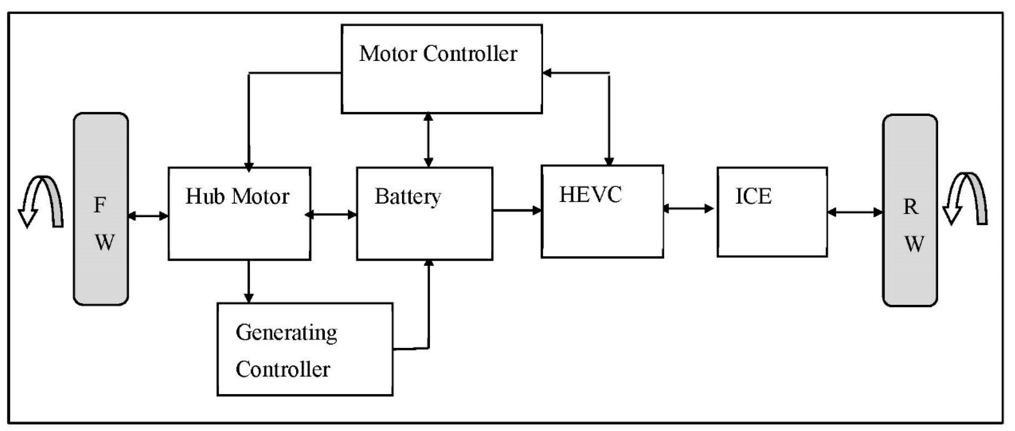
28]. In reference to the two-wheelers where conventional engines directly power the rear wheel of the vehicle using Continuous Variable Transmission (CVT), the easiest hybridization is possible by installing a hub motor to the front wheel. This is the best achievable parallel combination in scooters called “Through-the-Road” (TTR). The benefit of TTR architecture is to power the wheels directly by either a conventional or electrical power source with minimum energy losses. In TTR, throttle position corresponding to speed can be read by the controller; if the corresponding speed is less than 30 km/h, then the motor will be functional, whereas for higher speed ranges, the engine will be functional based on the efficiencies of power sources. This type of parallel architecture mainly benefits from either power source activation for optimized energy utilization [
12].
As energy management of an HEV depends on vehicle speed (traffic conditions), using power demand and acceleration traffic conditions can be detected. When the controller is integrated with the access to the real-time traffic data (google maps API), energy consumption forecasts are possible and the energy-efficient route can be suggested or energy consumption can be predicted and displayed in the odometer [
28,
29,
30]. The Fuzzy logic-based TTR HEV model and simulation for increased fuel economy using the current vehicle rate and Gross Discharge Rate (GDR) parameter is explained in this paper. A fuzzy logic-based system is synthesized wherein power flow is decided by energy management and GDR is derived from the current SoC value. The priori knowledge of trip distance based efficient energy management system is modeled [
28]. This paper integrates various control parameters and the effect of combined behavior of control parameters is tabulated with fuzzy and NN (Neural Networks) technique.
2. HEV Design Process
This paper details the research carried on a two-wheeler powered by an engine that is less than 100 cubic centimeters (CC) in capacity.
Table 1 gives the vehicle specifications. The hybrid conversion of two-wheelers has multiple challenges concerning EV kit placement, weight management, vehicle balancing, speed synchronization, throttle integration, smooth switching between power sources, add-on weight compensation, efficiency improvisation in traffic, and energy optimization, out of which the first three challenges are related to the physical placement of EV components on the vehicle.
Even electric vehicles are operated by fuel cells which are powered by hydrogen [
31,
32,
33,
34,
35,
36]. In a TTR-configured scooter, speed synchronization is an added advantage with simplicity in hybrid conversion. It also reduces driveline losses as the hub motor is placed in the front-wheel directly. Similarly, with engine mode active, the front wheel (motor wheel) is freely moving which helps to generate electricity for charging the battery. The motor also generates electricity during braking. These regenerations will enhance charge and fuel economy.
Figure 1 represents the vehicle architecture for TTR configuration with conventional and electrical subsystems. As most of the electric two-wheelers in India and China are powered by a hub motor and gasoline engines operate at a maximum of 25–30% efficiency, one-fourth of power equivalent to the engine is considered to select a hub motor.
2.1. Hub Motor Selection
The crucial component of an electric scooter is the electric motor selection which at the end decides the amount of torque at the wheel that meets the requirement of tractive effort at various speeds [
37,
38,
39]. Total vehicle weight is calculated including two passengers (driver and pillion), a hub motor, and a lithium-ion battery. The vehicle kerb weight of 95 kg, passenger weight of 148 kg, and 8.5 kg of hub and battery pack. The tractive effort is calculated assuming the maximum road inclination of
for gradient resistance [
16]. As the two-wheeler used in this study comes with CVT, the minimum wheel engagement speed of the CVT is adjusted to 2000 RPM which is close to 20 km/h vehicle speed. A detailed discussion on the alteration of the minimum engagement speed is discussed in
Section 2.4 of this paper. Resistive forces are calculated using the following relations:
The different forces acting on the vehicle are estimated assuming 0.015 of the coefficient of rolling friction, 0.33 coefficient of drag and 9.81 m/s
2 as acceleration due to gravity for
Froll. The frontal area of the vehicle is calculated to be 0.92 m
2 by including the driver’s approximate dimensions.
Net tractive effort is calculated to be 269.48 N and total wheel torque is calculated to be 54.699 Nm using a wheel radius of
. Finally, for 35 km/h speed, the total required motor power is calculated to be 531.6837 W. Based on these power requirement calculations, usually, a 1.2 times bigger motor power is chosen practically considering other unforeseen losses [
13] and it is the proper fitment in the wheel rim. To overcome the overload factors and other losses, the 850 W motor is chosen for hybrid conversion. The motor chosen is of a BLDC (Brushless Direct Current) direct drive with the specification given in
Table 2.
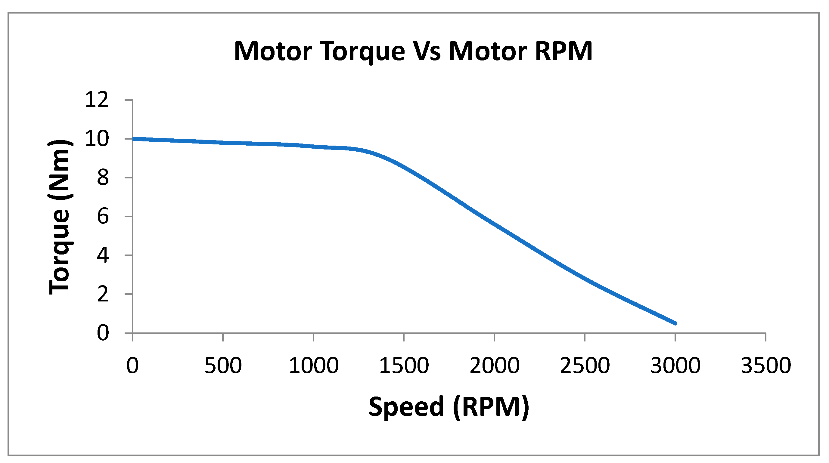
The motor, its controller, converter, and electronic throttle are installed on the vehicle for converting the conventional vehicle to hybrid. Energy optimization algorithms are simulated as per later details in the article for the specified objectives of fuel economy enhancement, energy management, and range extension. The controller drives the motor using a PWM signal and
Figure 2 shows the selected motor’s characteristics.
The BLDC hub motor uses three Hall sensors which are given as inputs to the motor controller. The motor controller is based on an Arm controller. Each phase of the motor has one Hall sensor which is used to read the speed of the motor. As per speed requirement, MOSFET-based three-phase converter switches are utilized for DC to AC conversion. It is observed that motor efficiency is high at lower speeds which is found to be convenient and economical for urban driving conditions.
2.2. Hybridization Factor (HF)
The Hybridization Factor (HF) is the percentage of maximum power of an installed electric motor to the sum of maximum power of an installed electric motor and a conventional IC Engine.
For an 850 W BLDC hub motor and ICE rated power of 3.68 kW, the HF is estimated as 18.76%. The detailed understanding of HEV development is applied for various powertrain architectures. The complexity of these architectures is based on HF, viz., micro-hybrid, mild-hybrid, series-hybrid, parallel-hybrid, series-parallel, complex-hybrid, power split etc. As formulated above, HF value can be chosen for any of the architectures with conventional power configurations. This value can be raised to enhance more dominant electrification by selecting more ratings of electrical systems. This factor enhances the percentage of electrification relative to conventional power, meaning that 100% HF determines full electrification which in turn indicates no conventional powertain system is present, i.e., pure-electric architecture. Similarly, 0% HF determines pure conventional architecture with no electrification present. Usually, in passanger cars the HF factor is in the range of 20% to 40%.
2.3. Battery Pack Selection
Lithium ferrous phosphate (LiFePO4) is chosen for the battery pack with a capacity of 1.44 kWh.
Table 3 shows the technical specifications of the battery pack. The battery pack is made by combining a set of cells in series and parallel for the required voltage and current. The form factor of selected cells is 18,650 cylindrical cells.
2.4. Throttle Integration
The installation and synchronization of an electronic throttle is a big challenge for two-wheelers as most of the conventional scooters have a mechanical throttle. Separate throttles for engine and motor are available but their integration is difficult for scooters. The integration of both throttles is necessary for hybrid mode. Various possible methods were explored to build a combined throttle for the engine and motor. The use of a variable resistor is found to be appropriate for building a combined throttle. Initially, experiments were carried out with a flex sensor which changes its resistance based on the bending angle. Later, it was found to be inconvenient as it was not producing repetitive values for the same throttle position.
It was finally found that regular potentiometers can be fixed at zero position of the throttle and its placement is made such that when the throttle is rotated, it will together rotate the shaft of the potentiometer correspondingly.
Figure 3 shows the placement on the potentiometer in mechanical throttle. A necessary reference supply is given to the potentiometer externally to convert resistance variation into voltages. This is unique, simple, and easily configurable with simple voltage divider circuitry. This configuration will be convenient for the driver as with a single throttle for two power sources, the driver does not need to focus on a separate EV throttle. Presently, this throttle is functional for part throttle range and the same is utilized for further development of the hybrid model.
2.5. Increasing the Variable Transmission (CVT) Engagement RPM
In addition to the throttle integration, one more challenge that arises in the integration and operation of the power sources is the minimum engagement RPM of the CVT. In India, 90% of the existing two-wheelers are fuelled using a carburetor. Carburetion technology cannot restrict the fuel entry during motor mode (when the engine rotated using the wheels). This leads to unnecessary fuel wastage and affecting the fuel economy. During motor mode, the vehicle should be powered only by a motor and the rear-wheel which is connected to the engine should freely rotate without engaging the engine. As the engine is directly coupled to the rear wheel using the CVT, the existing counterweights in the CVT will not engage the engine with wheels and vice versa at lower RPM of both the engine and wheel (at engine idling/vehicle being rolled by the diver manually). When the engine RPM increases (with the throttle) or wheel RPM increases during coasting down a slope, the engine engages CVT or CVT engages the engine. This will result in wastage of energy (fuel loss, engine friction, motor overloading and battery energy drain). Engagement RPM is the speed tuned by flyweights in the CVT to start moving the vehicle just above the idle speed. As such, the threshold for the engagement of the engine with wheels depends on the RPM of the engine and wheel.
The fuel wastage problem can be minimized by tuning the CVT. This will involve optimization of the driver and driven pulley weights based on experimentations to overcome the above-stated problem. The driver pulley was recalibrated with a different flyweight for adjusting engagement RPM. The flyweights were experimented with and adjusted such that it will increase the engagement RPM (by lowering the driver pulley weight). The increased engagement RPM ensures the attainment of the threshold. The flyweights play an important role in driving clutch and engagement RPM and it works on the principle of centrifugal force (
F) with flyweight mass (
M).
The experimentation is carried out with multiple iterations, out of which two iterations are: default flyweight and reduced flyweight. Reducing flyweight will reduce centrifugal force which extends clutch engaging RPM. Lighter flyweights will increase engagement RPM and heavier flyweights will decrease engagement RPM [
40,
41].
An experimental setup was built with a 1 kW BLDC motor, motor controller, CVT, and DAQ system. A lithium battery pack of 60 V, laser tachometers are used in the setup. Results are discussed here for the stock flyweight and reduced flyweight after integrating the CVT with the motor. For simplicity and precise control, an electric motor is mounted on the CVT instead of an engine [
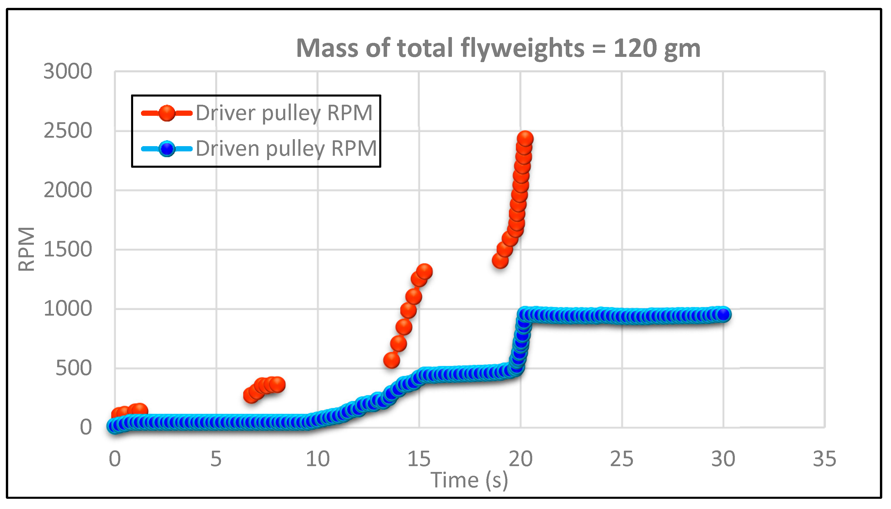
40]. The integrated throttle is used to drive the power source. Driver and driven pulley RPM are measured at 25%, 50% and 100% throttle with the help of tachometers and the results are presented in
Figure 4. The corresponding RPM readings are tabulated in
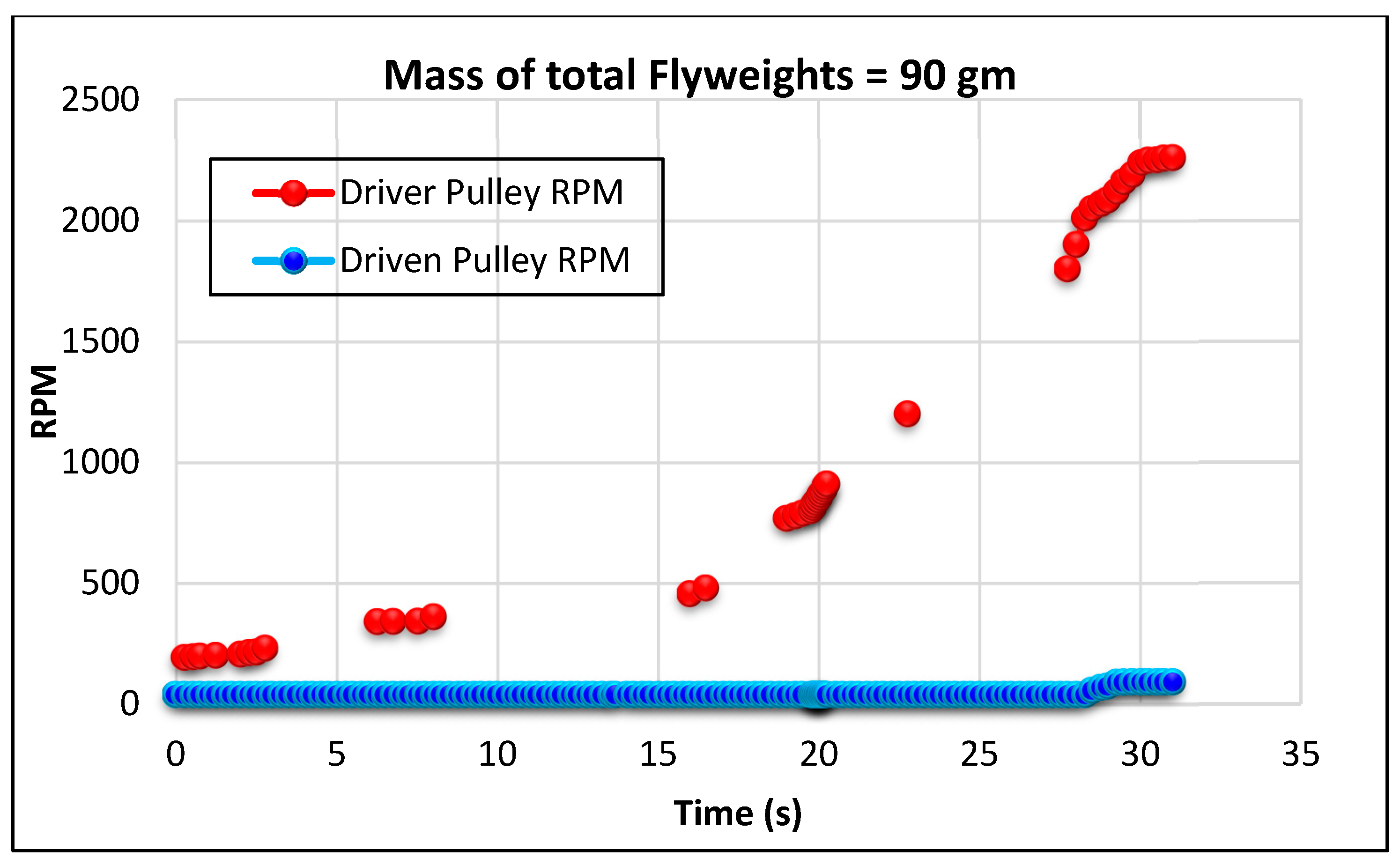
Table 4. In test-I default flyweights of a total 120 gm is used. In the test-II reduced mass of total flyweights is 90 gm and the corresponding results are given in
Figure 5 and corresponding RPM readings are tabulated in
Table 5.
As the motor is directly coupled to the front wheel, for 20 km/h vehicle speed, engine engagement RPM should be greater than 2000 (calculated according to the vehicle CVT specifications). This RPM is set for engagement of driven shaft to drive shaft. It is observed from the experiments that, reduced mass of flyweights increases the engaging RPM and the test-II indicates that the minimum engaging RPM is set for 20 km/h of vehicle speed. Tests were conducted on a chassis dynamometer to ensure the minimum engagement RPM of the CVT which will significantly reduce the fuel consumption during motor operation.
2.6. IMU (Inertial Measurement Unit) Based Data Acquisition System (DAS)
Before the actual test on the vehicle, DAS is designed which logs the real-time parameters into SD card-based memory. Data logging is carried out using the Arduino Mega platform for 6-axis Motion Tracking. Bosch BMI088 IMU sensor is interfaced with ATmega 2560 using I2C protocol with the output data rate of 100 Hz for acceleration and gyroscope. This semiconductor chip is useful for high-performance applications. The logged dataset in memory shows the precise measurements for acceleration and gyroscope which helps to obtain the actual road profile and also the road inclinations. The mathematical relation mentioned below is used for calculation,
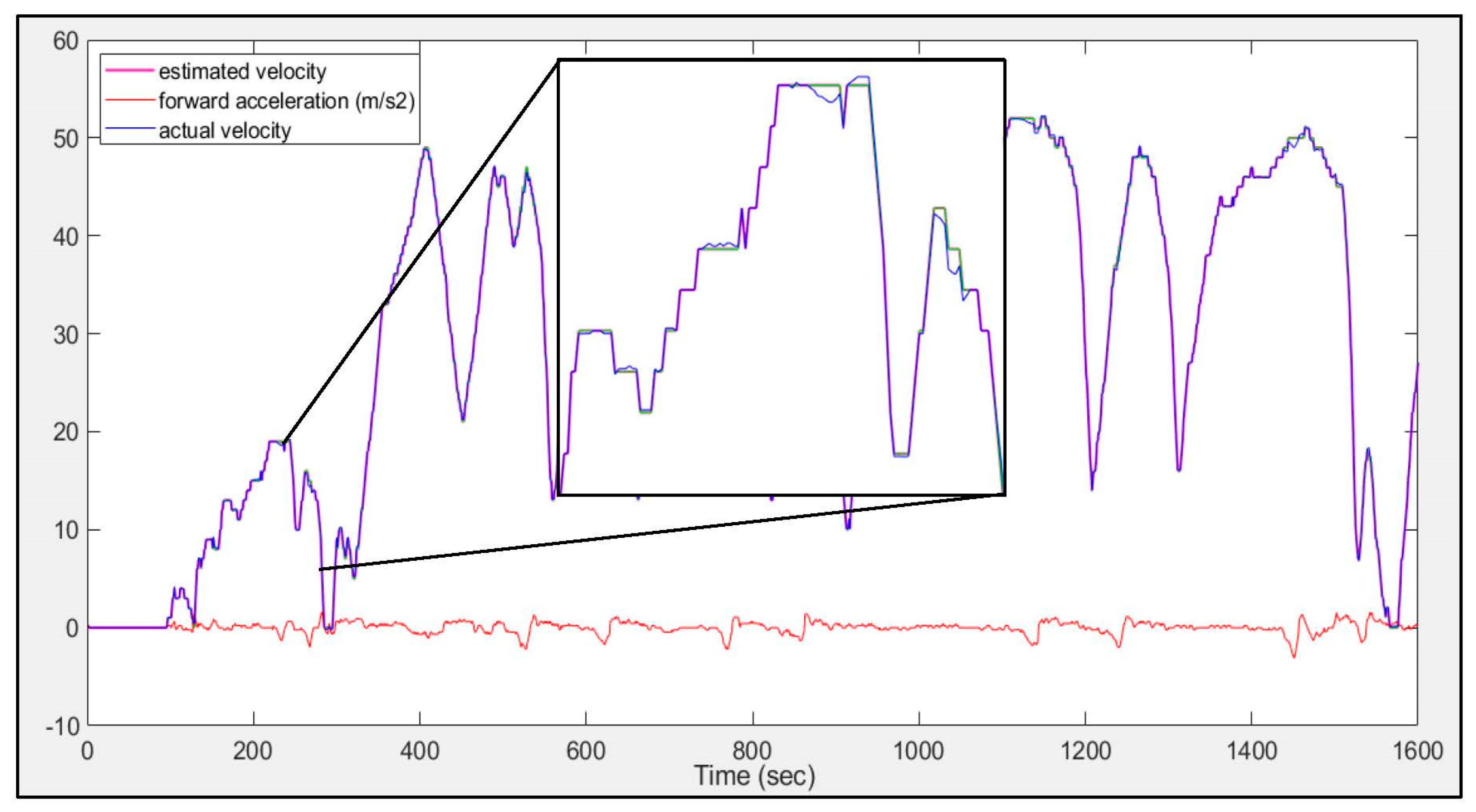
The sensor arrangement was kept such that the X-values of the accelerometer interpret lateral displacements, Y-values interpret forward and backward and Z-values interpret vertical displacements in terms of g-factor. As the vehicle does not have the speed sensor, DAS estimates the vehicle velocity correctly from Y-dataset. For verification purposes, the experiment was carried out in another vehicle that has a built-in vehicle speed sensor. The actual vehicle velocity and calculated velocity from IMUs acceleration are plotted in the Matlab environment as shown in
Figure 6.
A similar method is used in the simulation model for interpreting the velocity from inertial forces. This technique is useful to log the vehicle speed information from acceleration and also to check the profile of the road with a lower development cost. Real-time 6-axis clock data improve the data accessibility which eliminates the need for a vehicle speed sensor.
2.7. Compensation for Add-On Weight
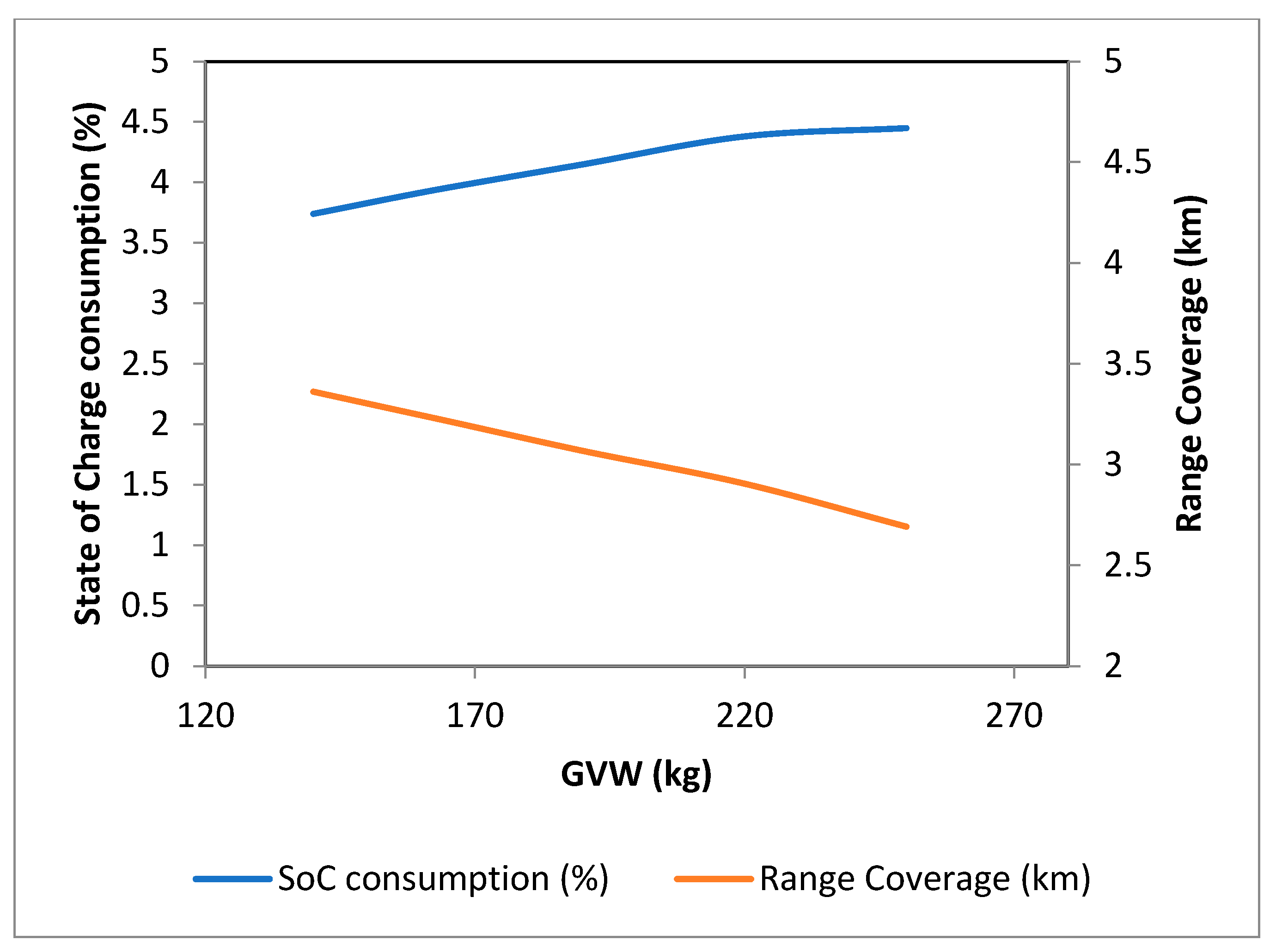
One more challenge with this system is when the vehicle is modified for hybrid, extra components get added which finally adds to the weight of the vehicle. This extra weight will additionally load for the engine as well as the EV. Usually, a conventional vehicle’s major weight contributor is the engine and its components. Based on the vehicle weight difference that is calculated below, EV kit weight addition can be compensated by engine downsizing. Lowering the vehicle weight will improve the range of the vehicle. This is verified in the Simulink model. The weights of all Indian scooters are tabulated. The approximately 110 CC scooters running on roads are chosen here. Minimum weight of scooter is found to be 82 kg whereas maximum weight is found as 115 kg. Hence, using these weights with passanger is selected for gross vehicle weight (GVW) range and model is simulated. As the weight of the vehicle increases, SoC consumption will surely increase.
Figure 7 shows the simulation result for GVW-wise variation on SoC consumption and range coverage for scooters with one drive cycle of “World Harmonized Motorcycle Test Cycle” (WMTC) part-1. Here, SoC consumption is the battery energy utilized by the vehicle to propel the vehicle concerning specified GVW on the x-axis. Hence, to increase the range in EV mode, GVW should be lower.
3. Operation of HEV Modes
The usual operation of HEV is distinguished based on three selection modes. The driver can select any mode for vehicle propulsion.
3.1. Engine Mode
This mode resembles a conventional vehicle. In this mode, the rear wheel will propel the vehicle. Motor and hybrid modes are OFF in this case; there is also no charge generation.
3.2. Motor Mode
This mode resembles a pure electric vehicle. The hub motor will drive the front wheel using the energy from the lithium battery pack. During this mode, engine is in the OFF state and regeneration is carried out during braking.
3.3. Hybrid Mode
When hybrid mode is selected, the hybrid controller decides the switching of two sources based on optimization algorithms. This is the most energy-efficient mode where the controller decides which power source to operate [
42,
43,
44,
45,
46]. In parallel with TTR configuration, when the motor is functional, charging the battery is done using regeneration during braking alone and when the engine is functional, based on the SoC, the hub motor will generate electricity to charge the battery pack.
Table 6 summarizes various operational modes of the system.
4. HEV Control Design Parameters
For efficient energy utilization, vehicle-level hybrid control is constructed with four control parameters which are given in
Table 7. The first parameter is the battery pack energy regulation. The state of charge is the indicatior of the battery pack energy content in terms of percentage. When a vehicle is propelled, energy drains from the battery and gradually decreases the available SoC. This parameter needs to be monitored continuously and regulated by the controller as rapid discharging, overcharging, and discharging below the minimum cutoff voltage may lead to battery failure. Studies show that for the capacity retention, SoC of the battery should be maintained above the lower threshold [
42,
43,
44,
45] and once the energy limit is beneath the lower threshold then the battery pack needs to charge instead of being used more [
46,
47,
48].
The second important control parameter I thes driver torque demanded. It is a known fact that conventional engines have better efficiency at higher load or torque ranges. On the other hand, the motor has better operating efficiencies at start-up (lower operating speeds). Hence, for urban driving, motors are preferred. Vehicle speed and traffic are the additional intelligent controls that also decide the switching algorithm. Maximum motor operation enhances the economy which is optimized for traffic conditions in urban areas. As scooters are primarily useful for intra-city commutation, optimization for traffic conditions enhances economy considerably. A control strategy for traffic detection with the remaining control parameters is applied and switching is regulated based on it. The vehicle speed and traffic conditions are simulated and controls are applied.
The
Table 7 shows the summary of the control strategy based on which controller switching is implemented. SoC Low_threshold is set as 0.3 and SoC High_threshold is set as 0.9. For demanded torque, threshold is set as 10 Nm. Vehicle speed threshold is set to 10 km/h.
The multiple methods of switching optimization, SoC, torque demand, vehicle velocity including traffic-based optimization are implemented in scooters and the challenges faced during optimization and implementation of these methods are discussed in the next section. This hybrid mode functionality is verified with three switching methods and simulation results are discussed in the controller part.
5. HEV Control Strategies
To apply the control strategy, base model of TTR configuration is prepared in Matlab and Simulink environments.
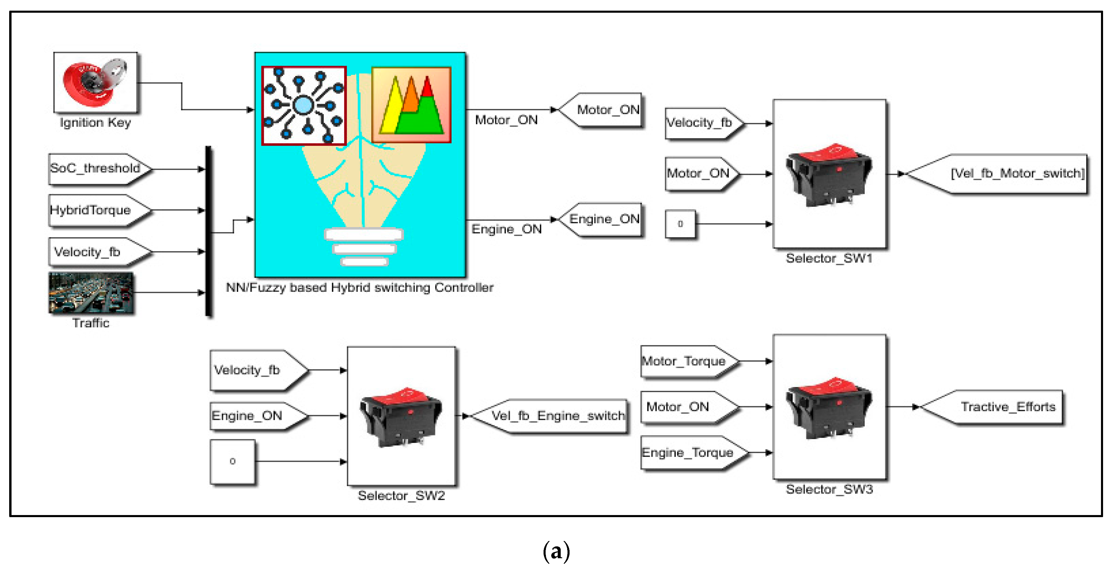
Figure 8 shows the simulation model for the specifications of chosen electrical components and vehicle for TTR configuration. The switching performance of the Motor and ICE are decided by Fuzzy based or NN based controller. Control algorithm and parameters are discussed in
Section 6.1 for Fuzzy logic and
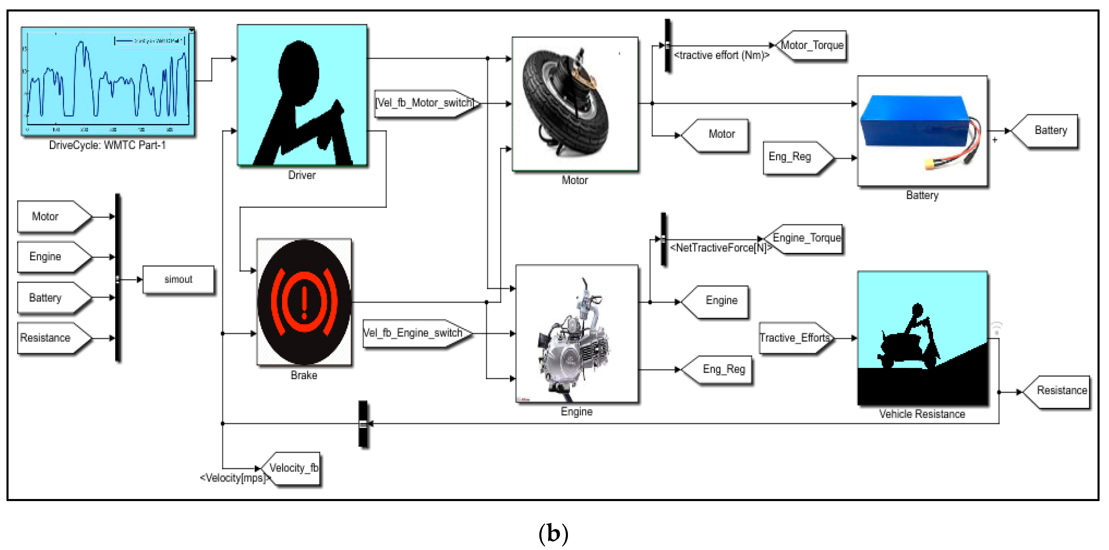
Section 6.2 for NN based methods. WMTC drive cycle is selected for the model and it gives vehicle speed in km/h to the driver subsystem as shown in
Figure 8b.
The driver block is responsible for driving the vehicle as per the drive cycle speed. This subsystem calculates differences between true vehicle velocity and the drive cycle velocity with respect to the vehicle’s torque demand and torque losses determined. In short, it also has vehicle-demanded speed as feedback velocity (Vf/b) which is the estimation from net forces and torques acting on the vehicle in the resistance subsystem discussed in further points. The estimated difference and PI control block is tuned as per the automated driver behavior.
The motor subsystem is the primary propelling subsystem for a hybrid vehicle. As it is an in-wheel motor it directly provides power without any transmission ratio factor. It is responsible for running the vehicle on EV mode with estimation of net propelling torque
as follows,
This net tractive effort is given to vehicle resistance subsystem where different on-road resistive forces are applied on the vehicle. The lithium-based battery subsystem estimates battery capacity using battery current consumption.
where,
is the internal resitance of lithium cell and
is open circuit voltage of battery. The full charged battery pack is of 1.44 kW represents 100% SoC. The SoC is determined by the below equation which indicates the remaining battery pack capacity,
where,
indicates battery energy capacity,
is initial SoC available with battery and
represents consumed or used battery energy. A suitable working range of the lithium battery pack is decided in
Section 6 with switching control algorithms. Actual road forces are estimated in the resistance subsystem, viz., rolling, aerodynamic and gradient forces decide the inertial force and accordingly velocity is generated. This feedback velocity is useful for driver subsystem.
Engine subsystem is the conventional power source which includes all necessary engine and transmission data generated on a dynamometer. Hence, activation of ICE or motor is carried by fuzzy- or NN-based switching controller one by one. The results and observations of both controls are discussed in
Section 7. The controller starts working as soon as ignition key is moved to ‘ON’, the initial check will be for SoC when the vehicle is idle. If sufficient SoC is available, then the controller will start using the lithium battery pack to power the motor, otherwise it will crank the ICE. Further logical parameters are explained in the fuzzy logic-based hybrid switching controller (FLC) and NN controller sections.
6. Adaptive Control Strategy for Optimization
A controller should always perform efficient energy management. Better energy management can be achieved with efficient control strategies to fulfill the following goals:
- (1)
Consistent driving performance for a full driving range including switching performance.
- (2)
The battery is sufficiently charged.
- (3)
Optimized system efficiency of the engine, motor, and battery.
Adaptive control for energy management is implemented using two different control strategies. Initially modeling of hybrid switching is carried out only based on battery capacity. The classical fuzzy control system is demonstrated for various multivariable systems in the automobile. Hence, fuzzy control-based rules are set for control parameters which intelligently decide the switching. Neural network-based machine control algorithms also help to train the controller for decision making. Initially, the fuzzy rule-based switching controller is developed and a further NN-based switching controller is developed and results are tabulated.
6.1. Fuzzy Logic-Based Hybrid Switching Controller (FLC)
The fuzzy control system was invented in 1965 by Lotfi Zadeh which has been found to be very appropriate for multiple parameter control applications. Mamdani-type and Sugeno-type processing methodologies can be executed with the fuzzy control system. This system is wellknown for machine control especially when set rules are for partially true conditions. Hence it refers to the term “fuzzy” which implicates the logic in dealing with the concepts which cannot be expressed as TRUE or FALSE. These concepts are called as partial true concepts or degrees of truth. A fuzzy rule-based switching controller works on the predefined set of rules. It has extensive applications in industrial process control, securities and instrumentation.
Complex physical systems can be designed using FLC by the following steps:
Large systems are decomposed into a collection of various small subsystems.
Vary the plant dynamics in order to linearize the nonlinear dynamics about a set of operating conditions.
Organizing the a set of all control and output variables for the objective system.
Testing the output functionality for the defined set rules.
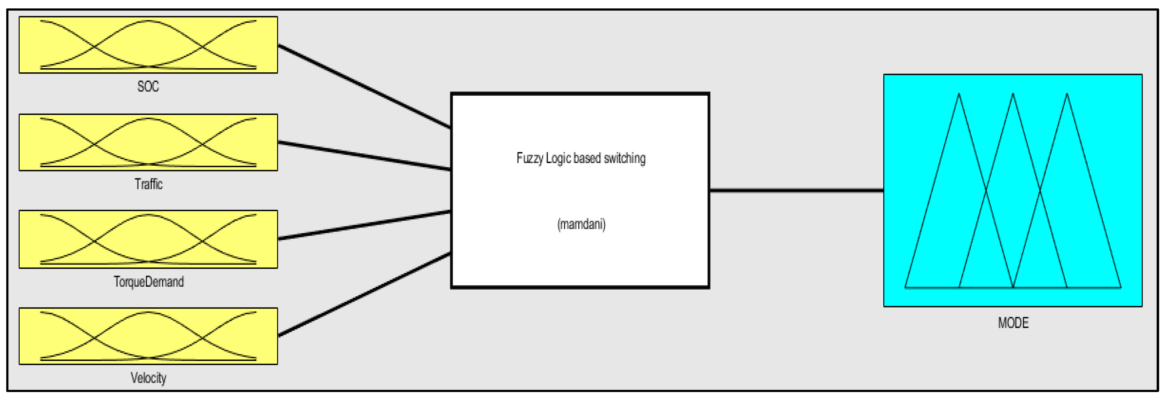
The fuzzy controller block is functional only when the ignition key is switched ON. Later, it decides the switching based on battery capacity, torque demand, vehicle speed, and road traffic condition. Hence, four input parameters are controlled in such a way as to decide the output state. Each input variable consists of multiple membership functions which classify it for appropriate ranges.
Figure 9 shows the controller block with control parameters showing the Mamdani-type fuzzy controller. According to the improvisation of efficient switching, all the parameters are expressed in the set of control rules. The defuzzification module uses the Center of Area as the defuzzification strategy. Each parameter is set for (Xmin, Xmax) boundary conditions. The SoC parameter is given a trapezoidal membership function with three ranges from its minimum to maximum range and transcription data were collected to form an input parameter vector. Similarly, all the other parameters are set for the membership functions from their minimum to maximum range. Road traffic conditions lead to a significant fuel consumption.
Acceleration and braking continuously increase fuel consumption and also braking leads to loss of energy in the form of heat. This challenging situation is taken care of by the hybrid controller and if sufficient battery pack capacity is available, the controller may decide to use motor mode wherein braking energy is also utilized in regeneration.
Figure 10 shows SoC ranges SoC_Low, SoC_Moderate and SoC_High. EV functionality will be ON if SoC is higher than SoC_Low threshold.
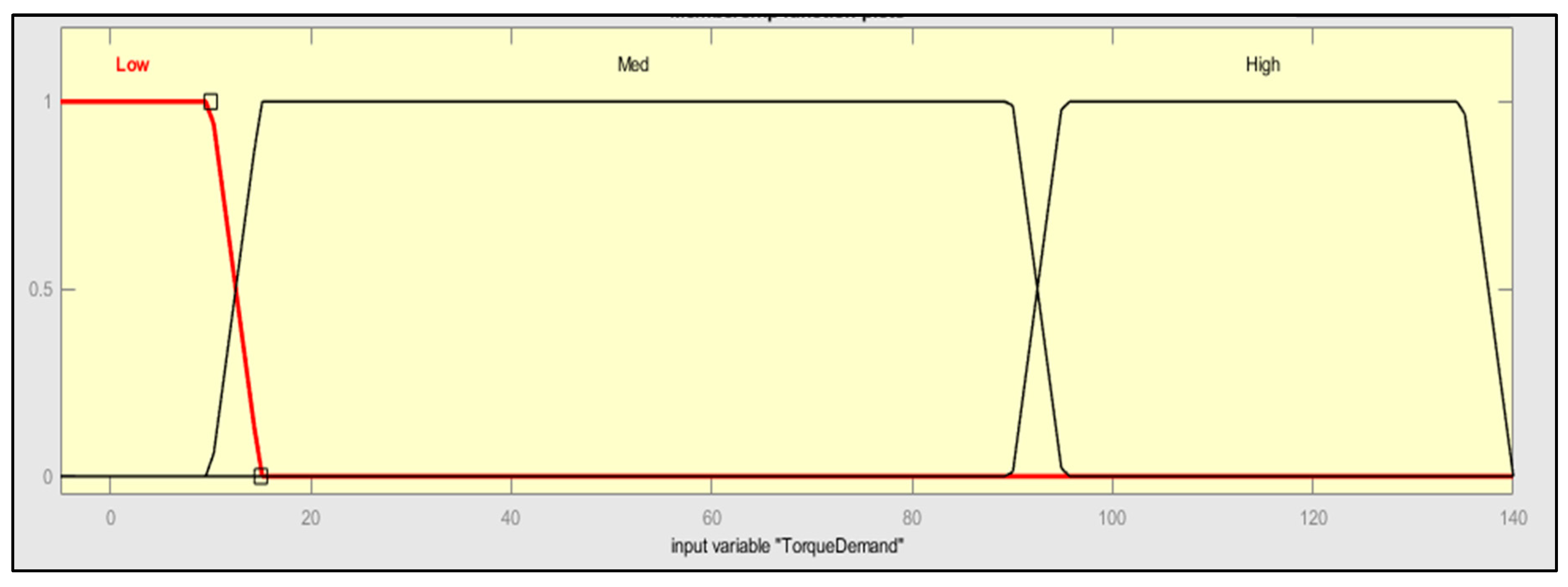
The torque demand parameter is distributed from 0 to 140 Nm, the motor is capable of delivering a rate of 9Nm, and hence if more torque is needed, the controller starts the engine. If the controller estimates uphill driving from velocity and torque demand, controller will start in hybrid mode.
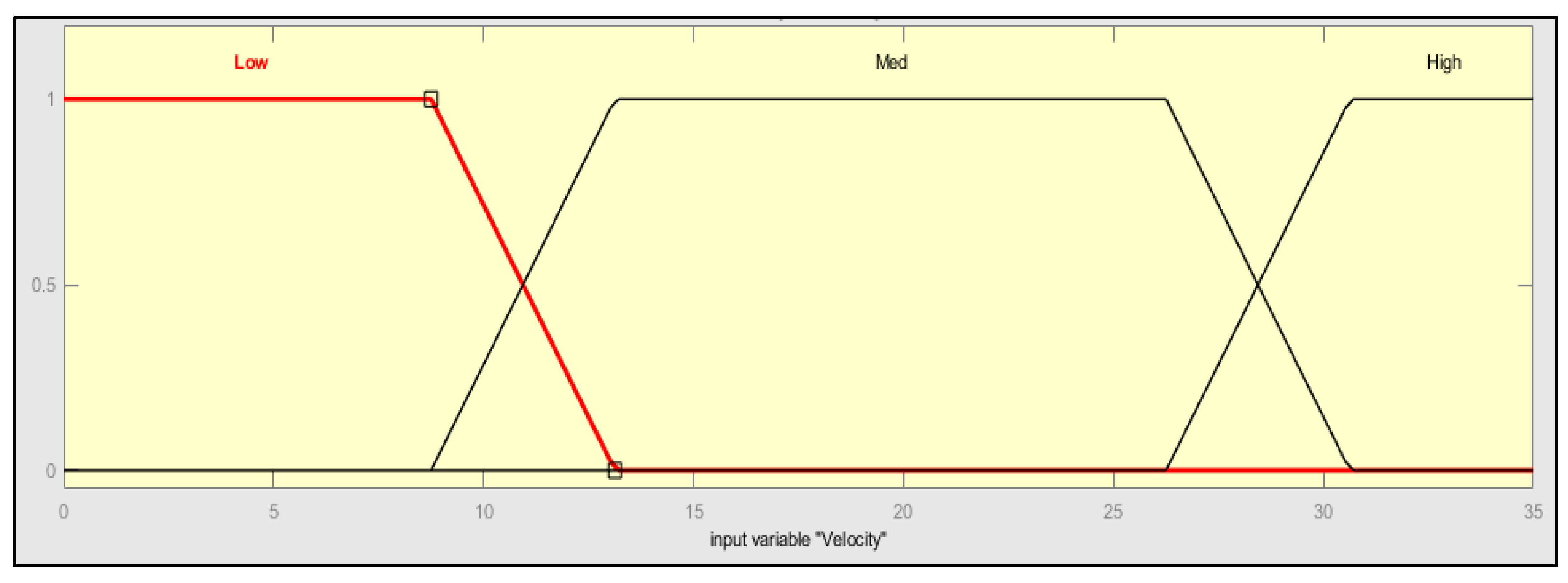
Velocity and traffic are interrelated in the model. Velocity is the parameter used for understanding the gradient and torque demand. For simulation, traffic is detected from the velocity data. The driving condition “Low” torque demand from
Figure 11 and “Low” velocity from
Figure 12 and are determined as traffic.
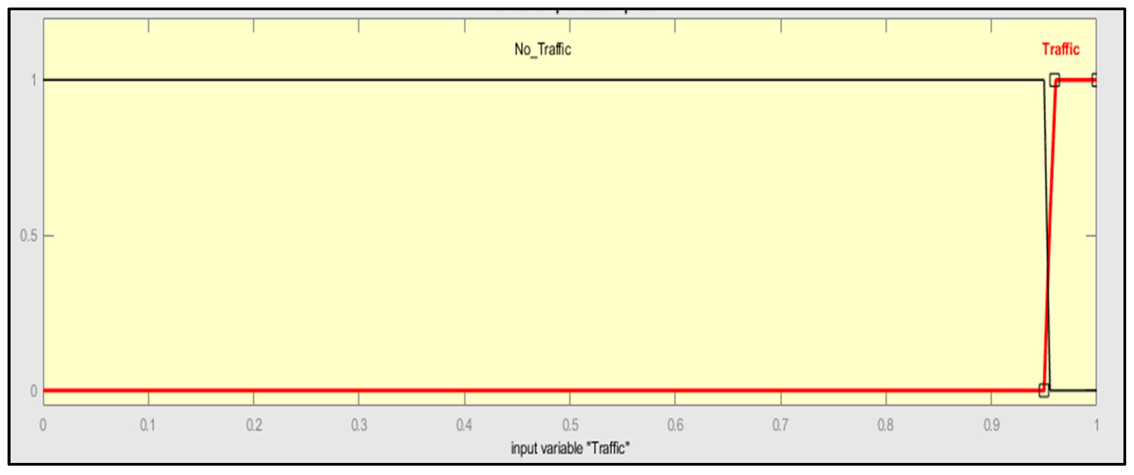
Figure 13 shows the membership functions for SoC and if traffic is estimated, traffic parameter is set to binary “1”. All the membership functions and rules are represented as below:
SoC > 100 (unit- percentage).
TorqueDemand > 140 (unit-Nm).
Velocity > 35 (unit-km/h).
Traffic >1 (unit-binary bit).
Efficiency-based rules are applied to decide switching between engine and motor. The traffic bit is decided based on the following rule:
If ((velocity < OR = previous velocity) AND (velocity < threshold), traffic = 1; or else traffic = 0;
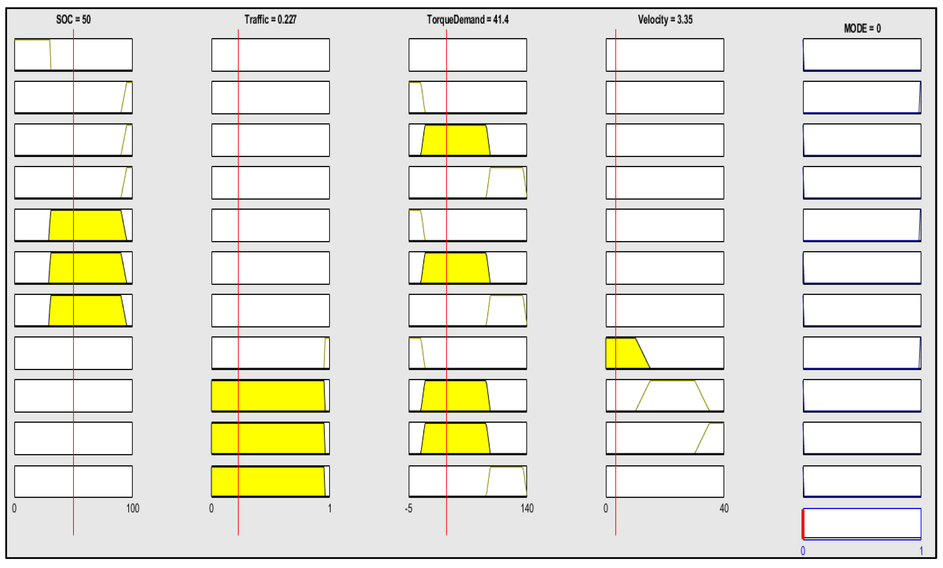
It defines the traffic condition for the simulation. All the rules are shown in the rule check (
Figure 14). The testing of the different vehicle conditions can be done manually using the rule check bar. Once the testing is done successfully, the fuzzy logic-based switching is based on the input parameters. Hence, in such cases, energy management plays a vital role. Each control parameter has been assigned appropriate membership functions and each set rule is tested in the Simulink environment as given below. In the rule check interface, the user can check all sets of rules by the manual method and can predict the output in the last output column.
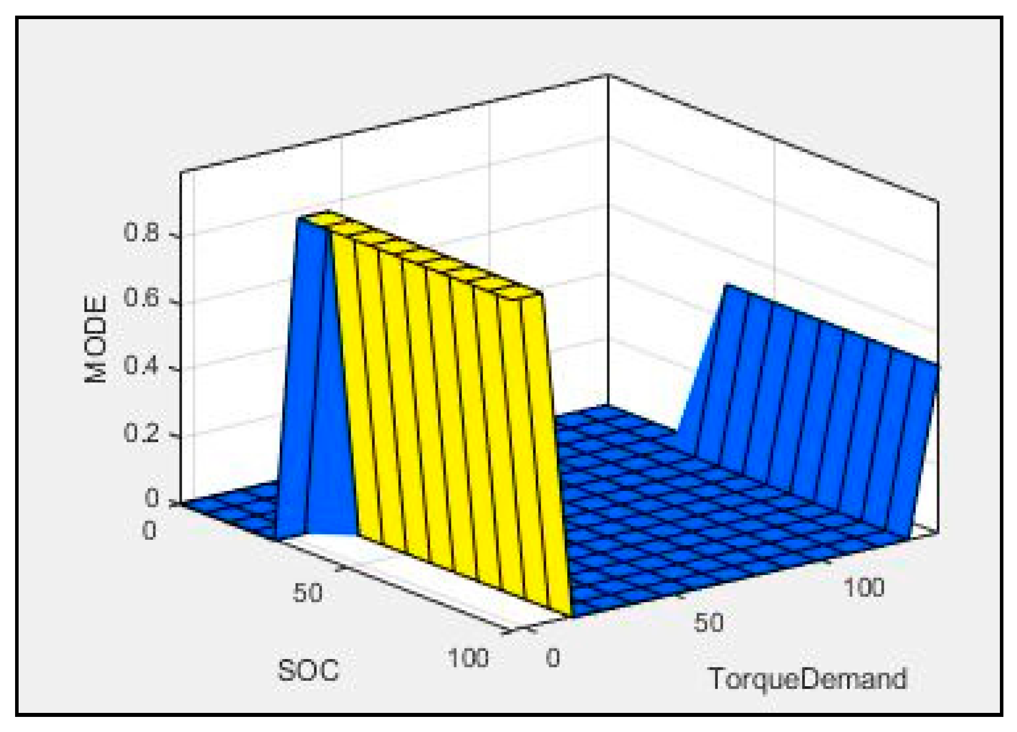
The surface plot is an interface that graphically indicates the applied rules in the three dimensions.
Figure 15 shows the surface plot for fuzzy control based switching algorithm. This surface plot depicts the output concerning any two control parameters, as below it indicates “MODE” output along with “SoC” and “TorqueDemand” control parameters. Users can select any two control parameters and accordingly observe the surface plot for output.
6.2. Neural Network-Based Hybrid Switching Controller
Artificial neural networks, commonly known as neural nets, are a network of activation functions based on statistical error measurements introduced with non-linearity. The activation functions interact with each other and together form a structure emulating the human brain with neurons. The network takes in input from several parameters and processes the information to deliver the desired output. The development cycle of a neural network involves determining the number of input nodes, the number of hidden layers, the number of activation function units in each layer, and finally the output layer. The addition of multiple units in a single layer or multiple layers as a whole tends to increase the computation time but renders accuracy and precision in terms of decision making.
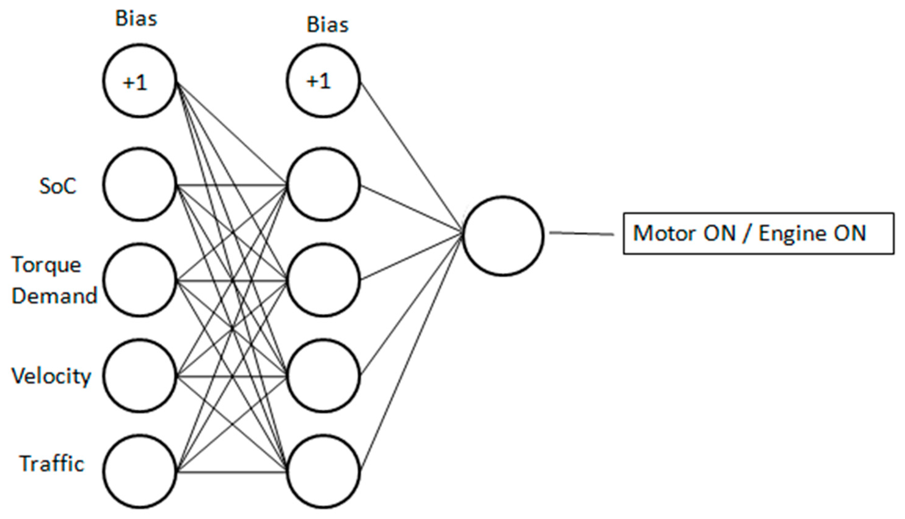
Concerning the current application of NN in the HEV switching controller, the four input parameters—battery SoC, traffic condition, velocity, and torque—demanded the percentage of true positive and true negatives from the output model, and depends on the training used to determine the suitable weights for the neural network. The data required for training the model are determined using a combination of some real-time scenarios and some holistic assumptions. This is the application of NN for machine learning wherein training of a machine for set rules with an output is used. The offline classification method is used wherein recorded datasets are used to train the model. Four input parameters are inputed to the first layer and most output layers define the switching of motor and engine based on control logic. The middle hidden layer has four neurons. The training data with 18,012 data points were used to train the model.
The supervised learning method is implemented using labeled data to feed as an input vector in the NN model. The data obtained from the experimentation phase is then categorized as training, cross-validation and testing data in the ratio 70:15:15. The purpose of using a cross-validation dataset is to ensure that the data generalize well enough before being fed into the test model. There can be multiple models using the activation functions and the regularization parameters if used might seem to fit well with a certain test dataset which mitigates the chances of complete generalization. Training neural networks involves procedures like stochastic gradient descent (SGD) and backpropagation.
The development and testing of NN have been carried out using the NN toolbox from MATLAB. The size of hidden units in a single layer was varied to obtain the best possible outcome in terms of accuracy and performance using the confusion matrix and ROC.
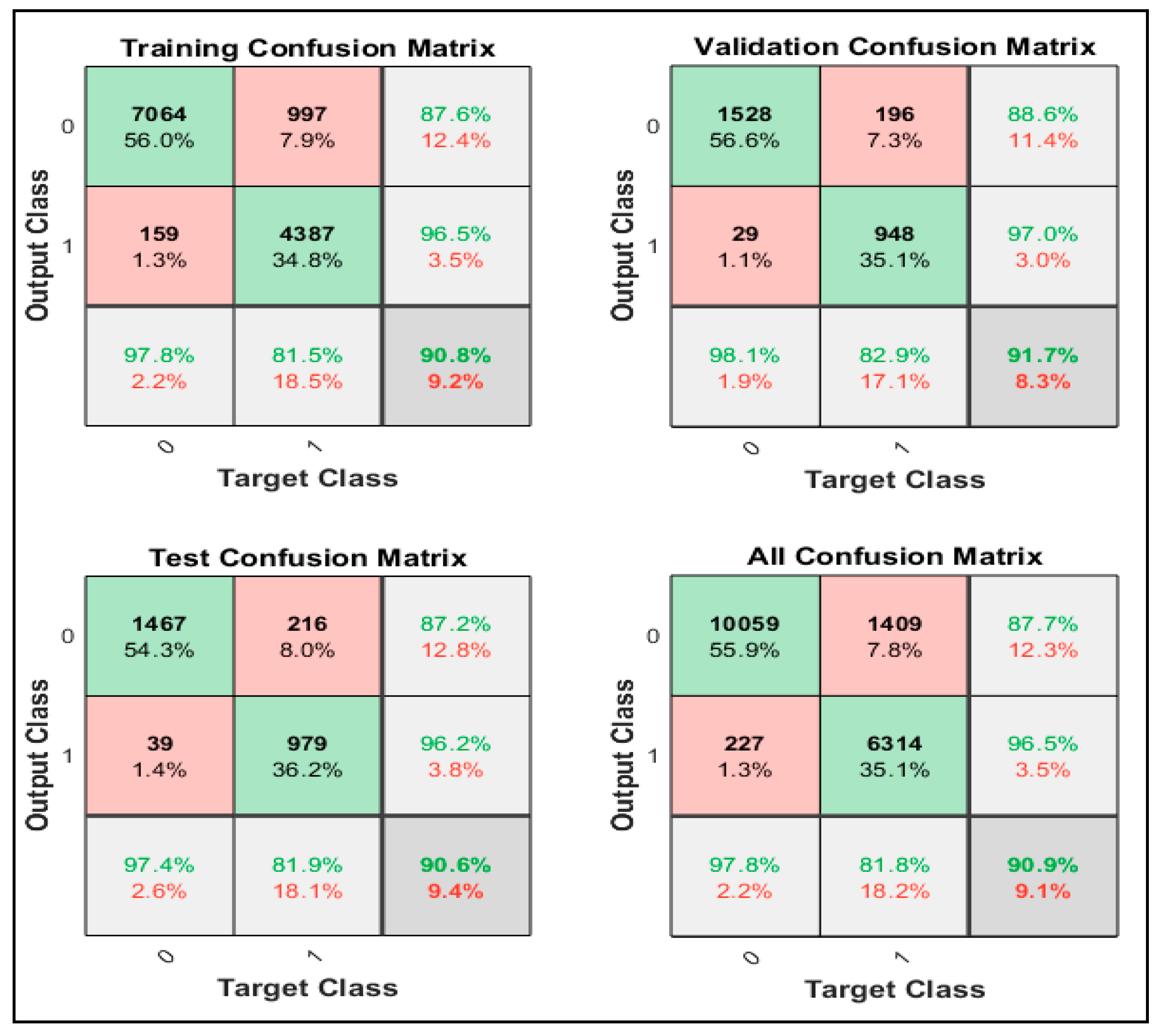
Figure 16 shows the block diagram of Neural Network based switching control for the best possible outcome. The best performance metrics were observed in four units in a single hidden layer. The confusion matrix defines the true positive and true negative. The confusion matrix is an N × N matrix. It is a base matrix for evaluating the performance of a classification model. Here, N represents the number of target classes. The network compares the real target values with those anticipated by the machine learning model. This gives us an all-encompassing view of how well our classification model is performing and what sorts of mistakes it is making. The confusion matrix obtained for the current model is shown in
Figure 17.
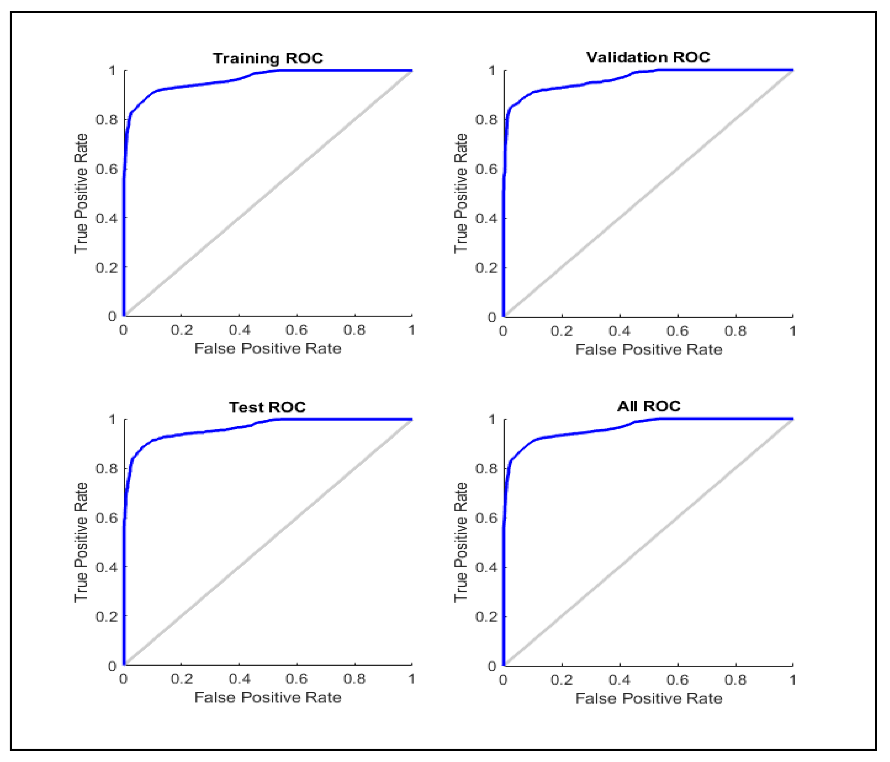
The ROC or receiver operating characteristic curve is a probability depiction of the true positives and false positives. The area under this curve is often referred to as AUC which has a range from 0 to 1 and determines how well the model performs in classifying the input data correctly as motor mode or engine mode; it defines the measure of separability between two classes.
Figure 18 depicts the ROC-AUC of the model which indicates that the area is close to one and the model performs well in classifying the modes.
Use of NN is a performance- or metrics-driven approach as it depends heavily on the data collected, processed and fed for decision making. Thereare some more metrics that define accuracy and model performance. After validating all the metrics, the model can be referred for deployment in the testing phase for unseen data.
The few fundamental terminologies are precision, recall, accuracy and F1-score. Precision determines correctly predicted positive values with respect to the total positive predicted values. It is also referred to as “Specificity” estimated. Recall defines correctly predicted positive values with respect to the total correctly predicted values. It is also referred to as “Sensitiviy”. Accuracy defines the correctly predicted values to the total predicted values and F-1 score is the harmonic mean of precision and recall. It is a widely used statistical term that provides statistical inference of the data at hand. Based on its mathematical equations, estimated precision is 0.877, recall is 0.978, accuracy is 0.909 and F1 score is 0.925.
7. Results and Discussion
Energy consumption calculations and results are carried out with the below steps. Initially, model is simulated on engine mode only with WMTC part-I, II, III drive cycles with speed limit of 50 kmph. It is observed that the vehicle is covering 18.86 km for one drive cycle as shown below. For pure electric mode, initial SoC is set at 100; the same for hybrid models is set at 31.5 for estimating switching results.
Fuel consumption for engine is calculated based on mileage (M) of the vehicle. Typical mileage is between 55 and 60 km and assumed as 55 km/L. Hence, fuel consumption (FC) in g/h (unit) for vehicle power (
, break-specific fuel consumption (BSFC) is calculated as below,
FC can also be calculated with mileage as below:
Considering 55 km/L as M value and
. as
, FC is estimated 680.81 g/h. Hence, fuel consumption estimation of vehicle with 50 kmph speed for 55 km/L mileage is 680.81 g/h. With a pure conventional configuration, simulation results in 0.3036 kg fuel consumption.
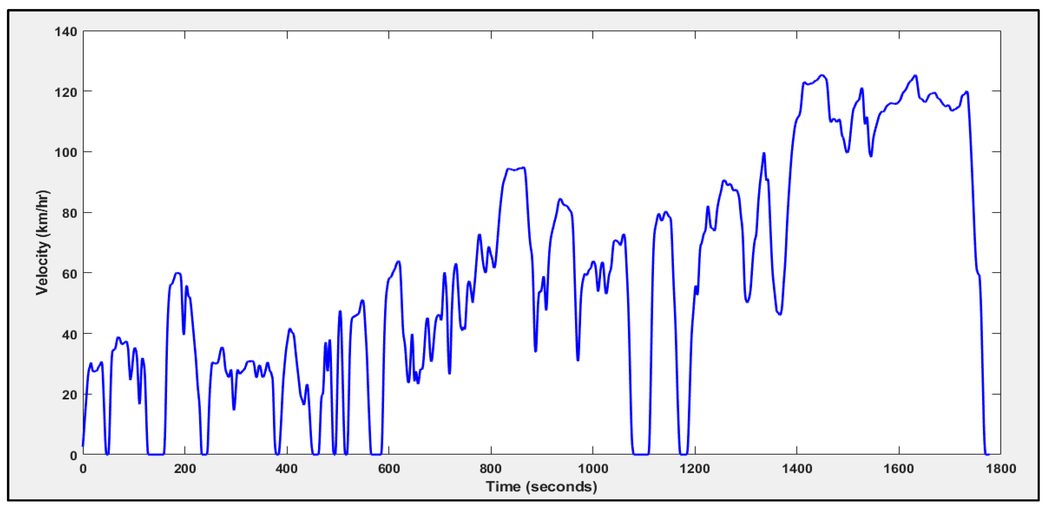
Figure 19 shows the WMTC driving cycle used for Matlab and Simulink based simulations.
Figure 20 shows the fuel consumption results during simulation of WMTC with switching methods.
When pure EV mode is functional then battery pack energy is utilized by hub motor where it consumed 0.464 kWh of energy. The total consumption is from 1.44 kWh of battery pack capacity in SoC term. In this mode, 66.35 SoC is utilized by battery hub motor with an approximate mileage of 38 kms. Fuzzy- and NN-based switching methods consumed 0.2152 kg and 0.1738 kg of fuel, respectively. The observations section discusses about energy consumption in detail.
8. Observations
Energy consumption for the pure SoC-based, fuzzy logic-based and NN-based switching controller are given below in the
Table 8. In engine-only mode, the conventional IC engine-based two-wheeler powertrain is simulated to comprehend the energy consumption for the defined duration of the drive cycle. The total fuel consumption amounted to 0.3036 kg which potentially provided 3.8550 kWh of energy to drive the vehicle. The energy consumption, in this case, seems to be at the higher end, thereby accounting for a higher quantity of carbon emission. From the fuel economy point of view, this model provided driving mileage of 46.85 km/L.
In motor-only mode, the entire energy requirement is provided by an onboard lithium-ion battery. The hub motor driving the wheels demands 0.4640 kWh of energy for driving range of 18.86 kms using the part-1 drive cycle of WMTC. The net energy consumption, however, is reduced because of the higher efficiency of the motor compared to IC engines. This provides the substantial benefit of an electric energy-based propulsion system for automobiles.
In the hybrid mode, conventional SoC-based hybrid switching accounts for 0.2233 kg of petrol consumption alongside 0.0544 kWh of energy consumption from the battery. However, the energy consumption seems to be increased in this case due to the charge sustenance mode of operation of the vehicle by starting the engine when SoC drops below 30.
Fuzzy logic-based switching takes in multiple inputs like SoC, torque demand, velocity, and traffic condition. Using these input parameters, superior control is achieved over SoC-based hybrid switching model. This accounts for better energy efficiency for the reduced energy consumption of 2.7756 kWh. The fuel consumption as well as the energy consumption from the battery has reduced due to the improved accuracy of the control system. Neural network-based switching witnesses a further drop in total energy consumption resulting in minimum carbon emissions among all the considered types of operations. The emulation of the human brain in the network for decision making provides better control and accuracy.
Author Contributions
Conceptualization, S.K.-N., R.K.C. and S.P.; methodology, S.K.-N.; software, S.K.-N.; validation, S.K.-N. and R.K.C.; formal analysis, S.K.-N. and R.K.C.; writing—original draft preparation, S.K.-N.; writing—review and editing, S.K.-N. and R.K.C., funding acquisition, S.K.-N.; All authors have read and agreed to the published version of the manuscript.
Funding
This research received no external funding.
Conflicts of Interest
The authors declare no conflict of interest.
References
- Schaltz, E. Electrical Vehicle Design and Modeling; APA: Washington, DC, USA, 2011. [Google Scholar] [CrossRef] [Green Version]
- Venkat, T.; Dhruv, S.; Sadashiv, K.A. Study on the Implementation of Hybrid Two Wheelers in the Indian Market 2008. Available online: www.irjet.net (accessed on 9 February 2020).
- SIAM. Available online: http://www.siam.in/statistics.aspx?mpgid=8&pgidtrail=14 (accessed on 15 May 2019).
- Rajashekara, K. History of Electric Vehicles in General Motors. IEEE Trans. Ind. Appl. 1994. [Google Scholar] [CrossRef]
- Han, H.; Yu, J.; Zhu, H.; Chen, Y.J.; Yang, J.; Zhu, Y.; Chen, Z.; Xue, G.; Li, M. SenSpeed: Sensing driving conditions to estimate vehicle speed in urban environments. IEEE Trans. Mob. Comp. 2014, 727–735. [Google Scholar] [CrossRef]
- Ehsani, M.; Gao, Y.; Gay, S.E.; Emadi, A. Modern Electric, Hybrid Electric, and Fuel Cell Vehicles: Fundamentals, Theory, and Design; CRC Press: Boca Raton, FL, USA, 2004. [Google Scholar]
- Walker, P.D.; Roser, H.M. Energy consumption and cost analysis of hybrid electric powertrain configurations for two wheelers. Appl. Energy 2015, 146, 279–287. [Google Scholar] [CrossRef]
- Wang, J.; Besselink, I.; Nijmeijer, H. Electric vehicle energy consumption modelling and prediction based on road information. World Electr. Veh. J. 2015, 7, 447–458. [Google Scholar] [CrossRef] [Green Version]
- Chehresaz, M. Modeling and Design Optimization of Plug-in Hybrid Electric Vehicle Powertrains. Master’s Thesis, University of Waterloo, Waterloo, ON, Canada, June 2013. [Google Scholar]
- Yao, E.; Yang, Z.; Song, Y.; Zuo, T. Comparison of Electric Vehicle’s Energy Consumption Factors for Different Road Types. Discret. Dyn. Nat. Soc. 2013, 2013, 328757. [Google Scholar] [CrossRef]
- Chang, W.-Y. The State of Charge Estimating Methods for Battery: A Review. ISRN Appl. Math. 2013, 2013, 1–7. [Google Scholar] [CrossRef]
- Sabri, M.F.M.; Danapalasingam, K.A.; Rahmat, M.F. Improved Fuel Economy of Through-the-Road Hybrid Electric Vehicle with Fuzzy Logic-Based Energy Management Strategy. Int. J. Fuzzy Syst. 2018, 20, 2677–2692. [Google Scholar] [CrossRef]
- Das, A.; Jain, Y.; Agrewale, M.R.B.; Bhateshvar, Y.K.; Vora, K. Design of a concept electric mini tractor. In Proceedings of the IEEE Transportation Electrification Conference (ITEC-India), Bengaluru, India, 17–19 December 2019. [Google Scholar]
- Tran, D.D.; Vafaeipour, M.; el Baghdadi, M.; Barrero, R.; van Mierlo, J.; Hegazy, O. Thorough state-of-the-art analysis of electric and hybrid vehicle powertrains: Topologies and integrated energy management strategies. Renew. Sustain. Energy Rev. 2020, 119. [Google Scholar] [CrossRef]
- Shen, C.; Shan, P.; Gao, T. A Comprehensive Overview of Hybrid Electric Vehicles. Int. J. Veh. Technol. 2011, 2011. [Google Scholar] [CrossRef]
- Shimizu, H.; Harada, J.; Bland, C.; Kawakami, K.; Chan, L. Advanced concepts in electric vehicle design. IEEE Trans. Ind. Electron. 1997. [Google Scholar] [CrossRef]
- Martínez, L.R.; Prieto, M.D. New Trends in Electrical Vehicle Powertrains; IntechOpen: London, UK, 2019. [Google Scholar] [CrossRef] [Green Version]
- Lanzarotto, D.; Marchesoni, M.; Passalacqua, M.; Prato, A.P.; Repetto, M. Overview of different hybrid vehicle architectures. IFAC PapersOnLine 2018, 51, 218–222. [Google Scholar] [CrossRef]
- Singh, K.V.; Bansal, H.O.; Singh, D. A comprehensive review on hybrid electric vehicles: Architectures and components. J. Mod. Transp. 2019, 27, 77–107. [Google Scholar] [CrossRef] [Green Version]
- Zurich, E.T.H. Energy Management Strategies for Hybrid Electric Vehicles, no. 18435. Ph.D. Thesis, ETH Zurich, Zurich, Switzerland, October 2009. [Google Scholar]
- Sciarretta, A.; Back, M.; Guzzella, L. Optimal Control of Parallel Hybrid Electric Vehicles. IEEE Trans. Control Syst. Technol. 2013, 2004. [Google Scholar] [CrossRef]
- Shankar, R.; Marco, J. Method for estimating the energy consumption of electric vehicles and plug-in hybrid electric vehicles under real-world driving conditions. IET Intell. Transp. Syst. 2013, 7, 138–150. [Google Scholar] [CrossRef]
- Haddoun, A.; Benbouzid, M.E.H.; Diallo, D.; Abdessemed, R.; Ghouili, J.; Srairi, K. Comparative analysis of control techniques for efficiency improvement in electric vehicles. In Proceedings of the IEEE Vehicle Power and Propulsion Conference, Arlington, TX, USA, 9–12 September 2007. [Google Scholar] [CrossRef] [Green Version]
- Danhong, Z.; Yan, Z.; Kai-Pei, L.; Qing-Quan, C. A study on fuzzy control of energy management system in hybrid electric vehicle. In Proceedings of the Asia-Pacific Power and Energy Engineering Conference, Wuhan, China, 28–30 March 2009; pp. 1–3. [Google Scholar]
- Cheng, Y.H.; Lai, C.M. Control strategy optimization for parallel hybrid electric vehicles using a memetic algorithm. Energies 2017, 10, 305. [Google Scholar] [CrossRef] [Green Version]
- Ahmadi, S.; Bathaee, S.M.T. ScienceDirect Multi-objective genetic optimization of the fuel cell hybrid vehicle supervisory system: Fuzzy logic and operating mode control strategies. Int. J. Hydrogen Energy 2015, 1–10. [Google Scholar] [CrossRef]
- Yuan, Y.; Zhang, T.; Shen, B.; Yan, X.; Long, T. A Fuzzy Logic Energy Management Strategy for a Photovoltaic/Diesel/Battery Hybrid Ship Based on Experimental Database. Energies 2018, 11, 2211. [Google Scholar] [CrossRef] [Green Version]
- Melsert, R.; Chandrasekaran, R.; Bandhauer, T.; Fuller, T.F.; Meisel, J. Design of a hybrid electric vehicle. In Proceedings of the 2008 IEEE Energy 2030 Conference, Energy 2008, Atlanta, GA, USA, 17–18 November 2008. [Google Scholar] [CrossRef]
- Song, G.; Yu, L. Estimation of Fuel Efficiency of Road Traffic by Characterization of Vehicle-Specific Power and Speed Based on Floating Car Data. Transp. Res. Rec. 2009, 11–20. [Google Scholar] [CrossRef]
- Morlock, F.; Rolle, B.; Bauer, M.; Sawodny, O. Forecasts of Electric Vehicle Energy Consumption Based on Characteristic Speed Profiles and Real-Time Traffic Data, Institute of Electrical and Electronics Engineers Inc. IEEE Trans. Veh. Technol. 2020, 69, 1404–1418. [Google Scholar] [CrossRef]
- Coralli, A.; Sarruf, B.J.M.; de Miranda, P.E.V.; Osmieri, L.; Specchia, S.; Minh, N.Q. Science and Engineering of Hydrogen-Based Energy Technologies—Hydrogen Production and Practical Applications in Energy Generation; Chapter 2-Fuel Cells; Academic Press: Cambridge, MA, USA, 2019; pp. 39–122. [Google Scholar] [CrossRef]
- Uchida, H.; Harada, M.R. Science and Engineering of Hydrogen-Based Energy Technologies—Hydrogen Production and Practical Applications in Energy Generation; Chapter 5–Hydrogen Energy Engineering Applications and Products; Academic Press: Cambridge, MA, USA, 2019; pp. 201–220. [Google Scholar] [CrossRef]
- Schieber, G.L.; Stechel, E.B.; Ambrosini, A.; Miller, J.E.; Loutzenhiser, P.G. H2O splitting via a two-step solar thermoelectrolytic cycle based on non-stoichiometric ceria redox reactions: Thermodynamic analysis. Int. J. Hydrogen Energy 2017, 42, 18785–18793. [Google Scholar] [CrossRef]
- Cozzarini, L.; Bertolini, G.; Šuran-Brunelli, S.T.; Radivo, A.; Bracamonte, M.V.; Tavagnacco, C.; Goldoni, A. Metal decorated carbon nanotubes for electrocatalytic water splitting. Int. J. Hydrogen Energy 2017, 42, 18763–18773. [Google Scholar] [CrossRef]
- De Luca, D.; Fragiacomo, P.; de Lorenzo, G.; Czarnetzki, W.T.; Schneider, W. Trategies for Dimensioning Two-Wheeled Fuel Cell Hybrid Electric Vehicles Using Numerical Analysis Software. Fuel Cells 2016, 16, 628–639. [Google Scholar] [CrossRef]
- Andaloro, L.; Micari, S.; Napoli, G.; Polimeni, A.; Antonucci, V. EVS29 Symposium A hybrid electric fuel cell minibus: Drive test. World Electr. Veh. J. 2016, 8, 131–138. [Google Scholar] [CrossRef] [Green Version]
- Silvas, E.; Hofman, T.; Murgovski, N.; Etman, L.F.P.; Steinbuch, M. Review of Optimization Strategies for System-Level Design in Hybrid Electric Vehicles. Institute of Electrical and Electronics Engineers Inc. IEEE Trans. Veh. Technol. 2016, 66, 57–70. [Google Scholar] [CrossRef]
- Yang, Y.; Zhang, Y.; Zhang, S.; Tian, J.; Hu, S. Control strategy of mode transition with engine start in a plug-in hybrid electric bus. Energies 2019, 14. [Google Scholar] [CrossRef] [Green Version]
- Jiao, X.; Li, Y.; Xu, F.; Jing, Y. Real-time energy management based on ECMS with stochastic optimized adaptive equivalence factor for HEVs. Cogent Eng. 2018, 5, 1–19. [Google Scholar] [CrossRef]
- Gawade, S.; Bari, J.; Anagolkar, N.; Ashok, D. To Optimise the Performance of Electric Powertrain by Tuning the CVT. IOP Conf. Ser. Mat. Sci. Eng. 2019, 624. [Google Scholar] [CrossRef]
- Arta, I.W.Y.; Arifin, Z.; Yudantoko, A. The Effect of CVT Rollers Weight on Power and Torque of Honda Vario 125 Engine in Garuda Hybrid Car 2017. J. Phys. Conf. Ser. 2020, 1700, 012064. [Google Scholar] [CrossRef]
- Mudassar, M.; Rashid, U.; Mudasser, M.; Awan, F.G.; Rashid, U. Development of a Cost Effective Power Control Unit For Hybrid Electric Vehie Drive: Techno-Economic Analysis of Distributed Generation for Micro grid application using Homer Pro View project Development of a Cost Effective Power Control Unit For Hybrid E. Sci. Int. 2016, 28, 1105–1111. Available online: https://www.researchgate.net/publication/328213817 (accessed on 24 June 2020).
- Vidal, C.; Malysz, P.; Kollmeyer, P.; Emadi, A. Machine Learning Applied to Electrified Vehicle Battery State of Charge and State of Health Estimation: State-of-the-Art, Institute of Electrical and Electronics Engineers Inc. IEEE Access 2020, 8, 52796–52814. [Google Scholar] [CrossRef]
- Wang, T.; Zheng, P.; Zhang, Q.; Cheng, S. Design characteristics of the induction motor used for hybrid electric vehicle. IEEE Trans. Magn. 2005, 41, 505–508. [Google Scholar] [CrossRef]
- Joseph, A.V.; Kumar, G.J.R. Switching control in hybrid vehicle system based two wheeler. Int. J. Autom. Smart Technol. 2017, 7, 15–19. [Google Scholar] [CrossRef] [Green Version]
- Suh, B.; Min, B.S.; Kim, S.J.; Lee, J.H. Plug-in hybrid systems newly developed by hynudai motor company. World Electr. Veh. J. 2012, 5, 191–195. [Google Scholar] [CrossRef] [Green Version]
- Zhou, Y.; Lian, J.; Ma, T.; Wang, W. Design for motor controller in hybrid electric vehicle based on vector frequency conversion technology. Math. Probl. Eng. 2010, 2010. [Google Scholar] [CrossRef] [Green Version]
- Jiang, J.; Shi, W.; Zheng, J.; Zuo, P.; Xiao, J.; Chen, X.; Xu, W.; Zhang, J.G. Optimized Operating Range for Large-Format LiFePO 4/Graphite Batteries. J. Electrochem. Soc. 2014, 161, A336–A341. [Google Scholar] [CrossRef]
Figure 1.
Block representation of “Through-the-Road” (TTR)-parallel hybrid electric vehicle (HEV) system.
Figure 1.
Block representation of “Through-the-Road” (TTR)-parallel hybrid electric vehicle (HEV) system.
Figure 2.
Motor torque characteristics.
Figure 2.
Motor torque characteristics.
Figure 3.
Throttle integration using a potentiometer.
Figure 3.
Throttle integration using a potentiometer.
Figure 4.
Driver and driven pulley RPM for default flyweights of driver pulley.
Figure 4.
Driver and driven pulley RPM for default flyweights of driver pulley.
Figure 5.
Driver and driven pulley RPM for reduced flyweights of the driver pulley.
Figure 5.
Driver and driven pulley RPM for reduced flyweights of the driver pulley.
Figure 6.
Forward acceleration (m/s2), actual velocity and estimated velocity (from IMU sensor) curve.
Figure 6.
Forward acceleration (m/s2), actual velocity and estimated velocity (from IMU sensor) curve.
Figure 7.
Gross vehicle weight (GVW) effect on energy consumption and range coverage.
Figure 7.
Gross vehicle weight (GVW) effect on energy consumption and range coverage.
Figure 8.
(a) and (b): NN/Fuzzy control based switching hybrid simulation model of scooter.
Figure 8.
(a) and (b): NN/Fuzzy control based switching hybrid simulation model of scooter.
Figure 9.
Mamdani fuzzy logic controller.
Figure 9.
Mamdani fuzzy logic controller.
Figure 10.
Membership function of state of charge (SoC) parameter.
Figure 10.
Membership function of state of charge (SoC) parameter.
Figure 11.
Membership function of torque demand parameter.
Figure 11.
Membership function of torque demand parameter.
Figure 12.
Membership function of velocity parameter.
Figure 12.
Membership function of velocity parameter.
Figure 13.
Membership function of traffic parameter.
Figure 13.
Membership function of traffic parameter.
Figure 14.
Rule check for the fuzzy logic controller.
Figure 14.
Rule check for the fuzzy logic controller.
Figure 15.
Surface plot for the controller.
Figure 15.
Surface plot for the controller.
Figure 16.
Neural network structure for HEV switching.
Figure 16.
Neural network structure for HEV switching.
Figure 17.
Confusion matrix.
Figure 17.
Confusion matrix.
Figure 18.
Receiver operating characteristic (ROC) plots.
Figure 18.
Receiver operating characteristic (ROC) plots.
Figure 19.
“World Harmonized Motorcycle Test Cycle” (WMTC) drive cycle.
Figure 19.
“World Harmonized Motorcycle Test Cycle” (WMTC) drive cycle.
Figure 20.
Fuel consumption results from switching methods.
Figure 20.
Fuel consumption results from switching methods.
Table 1.
Base Vehicle Specifications.
Table 1.
Base Vehicle Specifications.
| Parameters | Specifications |
|---|
| Model | 87.80 cc scooter Engine |
| Engine | Single cylinder, 4- stroke |
| Power | 4.93 HP (3.6 KW) @6500 RPM |
| Torque | 5.8 Nm @ 4000 RPM |
| Bore x Stroke | 51 mm × 43 mm |
| Ignition | Digital DC CDI |
| Gearbox | CVT (Automatic) |
| Tyre size | 3.00 × 10 |
| Kerb weight | 95 kg |
Table 2.
Motor Specifications.
Table 2.
Motor Specifications.
| Parameters | Specifications |
|---|
| Hub Motor type | BLDC direct drive |
| Hub Motor Power (W) | 850 W |
| Hub Motor Torque (Nm) | 9 Nm @ 1400 RPM |
Table 3.
Lithium ferrous phosphate (LiFePO4) Battery Pack Specifications.
Table 3.
Lithium ferrous phosphate (LiFePO4) Battery Pack Specifications.
| Parameters | Description |
|---|
| Battery Rating | 60 V 24 Ah |
| Single Cell | 3.2 V 6000 mAh (Prismatic Cell) |
| Capacity | 1.44 kWh |
| Charging Mode | CC-CV: Constant Current 0.25 CA (Cold Amps), constant voltage 60 V |
| Charging Voltage | 66 ± 0.1 V |
| Internal Resistance | <40 mΩ |
| Charging Current | 24A |
| Operating Temperature | 0–60 °C |
Table 4.
RPM observations for default flyweight mass.
Table 4.
RPM observations for default flyweight mass.
| Sr. No. | Throttle (%) | Driver Pulley RPM | Driven Pulley RPM |
|---|
| 1. | 25 | 359 | 43 |
| 2. | 50 | 1312 | 440 |
| 3. | 100 | 2431 | 951 |
Table 5.
RPM observations for default flyweight mass.
Table 5.
RPM observations for default flyweight mass.
| Sr. No. | Throttle (%) | Driver Pulley RPM | Driven Pulley RPM |
|---|
| 1. | 25 | 294 | 39 |
| 2. | 50 | 910 | 39 |
| 3. | 100 | 2260 | 91 |
Table 6.
Operational Modes of Vehicle.
Table 6.
Operational Modes of Vehicle.
| Modes of Operation | Engine Functionality | Electrical Functionality | Hybrid Functionality |
|---|
| Engine Mode | Engine power is used to propel the vehicle | OFF Mode | OFF Mode |
| Motor Mode | OFF Mode | Battery power is utilized to propel the vehicle
Regeneration during braking | OFF Mode |
| HEV Mode | ON when HEV controller demands | ON when HEV controller demands
Regeneration of charge during braking | HEV Controller based Optimization controls Engine and Electrical switching
Regeneration is active as per controller switchingmodes |
Table 7.
Summary of HEV control strategy.
Table 7.
Summary of HEV control strategy.
| Control Parameters | Control Design Functionality |
|---|
| State of Charge Regulation | SoC < Low_threshold; Engine Mode ON; Regeneration and Charge into Lithium battery during runtime
Low_threshold > SoC > High_threshold; Motor Mode ON; Regeneration during braking |
| Demanded Torque Control | If Demanded Torque lesser than a threshold; Motor Mode ON
If Demanded Torque higher than a threshold; Engine Mode ON |
| Traffic Control | If (Traffic AND SoC > Low_threshold AND Demanded Torque < threshold); Motor Mode ON; Regeneration of charge during braking
If (Traffic AND SoC < Low_thresholdAND DemandedTorque <threshold); Engine Mode ON; Regeneration of charge into Lithium battery
If (Traffic AND SoC < Low_threshold AND Demanded Torque > threshold); Engine Mode ON; Regeneration of charge into Lithium battery
If No Traffic; Switching Control irrespective of the Traffic control parameter |
| Vehicle Speed | If the vehicle speed is lesser than a threshold and vehicle speed is decreasing then traffic is detected
If the vehicle speed is higher than a threshold, then no traffic condition is detected |
Table 8.
Results and Observations.
Table 8.
Results and Observations.
| Type of Operation | Total FCM | Energy Consumption (kWh) | Total Energy Consumed |
|---|
| Kg | Petrol | Battery | kWh |
|---|
| Engine-only | 0.3036 | 3.8550 | Nil | 3.8550 |
| Motor-only | Nil | Nil | 0.4640 | 0.4640 |
| Hybrid SoC based | 0.2233 | 2.8360 | 0.0544 | 2.8904 |
| Hybrid with Fuzzy | 0.2152 | 2.7331 | 0.0425 | 2.7756 |
| Hybrid with NN | 0.1738 | 2.2073 | 0.0513 | 2.2586 |
| Publisher’s Note: MDPI stays neutral with regard to jurisdictional claims in published maps and institutional affiliations. |
© 2021 by the authors. Licensee MDPI, Basel, Switzerland. This article is an open access article distributed under the terms and conditions of the Creative Commons Attribution (CC BY) license (http://creativecommons.org/licenses/by/4.0/).


