Article

Assessing Finite Control Set Model Predictive Speed Controlled PMSM Performance for Deployment in Electric Vehicles

by
Abhishek Murali
1,
Razia Sultana Wahab
1,*,
Chandra Sekhar Reddy Gade
1,
Chitra Annamalai
1 and
Umashankar Subramaniam
2,*
1
School of Electrical Engineering, Vellore Institute of Technology, Vellore 632014, India
2
Department of Communications and Networks, Renewable Energy Lab, College of Engineering, Prince Sultan University, Riyadh 11586, Saudi Arabia
*
Authors to whom correspondence should be addressed.
World Electr. Veh. J. 2021, 12(1), 41; https://0-doi-org.brum.beds.ac.uk/10.3390/wevj12010041
Submission received: 30 December 2020 / Revised: 25 February 2021 / Accepted: 8 March 2021 / Published: 11 March 2021

Abstract

:
Electric vehicles (EVs) have the main advantage of using sustainable forms of energy to operate and can be integrated into electrical power grids for better energy management. An essential part of the EV propulsion system is the type of motor used to propel the EV. Permanent magnet synchronous motors (PMSMs) have found extensive use due to various advantages such as high power density, excellent torque-to-weight ratio and smooth speed profile over the entire torque range. The objective of this paper was to improve the dynamic response in the speed profile for different driving conditions essential in EVs. This was done by using the finite control set model predictive control (FCS-MPC) algorithm for PMSM and by comparing and evaluating the control strategies of a PMSM used in an EV by taking two case studies. The classical control, namely field-oriented control (FOC), of PMSMs is slow to adopt the dynamic changes in the system. The proposed FCS-MPC algorithm for PMSMs provides an improved dynamic response and a good steady-state response for the different driving conditions shown in both cases. In addition, the Worldwide Harmonized Light Vehicles Test Procedure (WLTP) is used to evaluate the FCS-MPC-controlled PMSM to depict its superior performance by matching its speed profile. The results are verified in the hardware in the loop strategy using OPAL-RT. Both the results confirm that the FCS-MPC algorithm, when compared with the conventional FOC, is superior in aspects of steady-state and dynamic responses for various torque and speed profiles.
Keywords:
EV; PMSM; FOC; MPC; speed; torque; HIL; OPAL-RT

1. Introduction

With an ever-increasing concern on the environmental impact of today’s vehicles and the limited resources of fuel available to power them, internal combustion (IC) engine-powered vehicles are slowly losing their value. Electric vehicles (EVs) are a great alternative to them due to their ability to be powered by energy generated from renewable sources such as solar, tidal, and wind energy, thereby removing their dependence on non-renewable fossil fuels. EVs also can supply power from their energy storage when at a standstill and can be integrated with the electric grid for overall energy management. Table 1 shows the nomenclature used in this article.
During acceleration while starting a vehicle, it is crucial to have high starting torque so that the vehicle can reach the top speed while driving the load. This is the region of constant torque. Once the maximum speed is reached, the vehicle then operates in constant power. This puts a limit on the speed that can be attained by the vehicle while driving the given torque.
Current vehicles that run on an IC engine do not have the same torque–speed graph, which necessitates the use of gear arrangements, leading to a mechanically complex system. It also suffers from having poor efficiency when being run at low speeds. EVs, on the other hand, use motors that can match the ideal graph for a vehicle. The permanent magnet synchronous motor (PMSM) is one such type of motor. It consists of a permanent magnet that acts as the rotor of the machine, and the stator includes windings wound either in distributed or concentrated form. The windings are given a three-phase AC supply, usually in star connection. The use of a permanent magnet means the machine can only operate at one speed, which is called the synchronous speed due to magnetic locking. The speed of the motor depends solely upon the frequency of the AC supply given to the stator PMSMs have found extensive use in such applications due to the following:
  • Able to provide high starting torque;
  • Higher torque and output power per unit volume due to the usage of permanent magnets;
  • High magnetic flux density in the air gap allows for better dynamic performance of the motor, which is essential when using EVs;
  • High efficiency since there are no energy losses in the field due to usage of permanent magnets;
  • Flux weakening technique can be used to increase the maximum speed that can be attained in the constant power region;
  • Motor is compact, and its construction is simple.
As the focus shifts more towards EVs, it is vital to control the motor to obtain proper torque and speed profiles for the EV. An important aspect is that the torque and speed keep changing throughout the ride. Therefore, the control strategy used for the PMSM must have an excellent dynamic response to deal with changing input. Furthermore, the algorithm must respond quickly to load changes. The classical field-oriented control (FOC) technique suffers from being a slow form of control and has a poor dynamic response for the current application of PMSMs in EVs. Model predictive control (MPC) is one such algorithm with a digital form of control [1]. It possesses the following advantages:
  • Uses a model for future prediction of control variables, thereby making it fast;
  • Good transient response due to the reduced number of controllers;
  • Incorporates a cost function which can have additional constraints such as switching frequency reduction, torque ripple minimization, etc. [2].
There has been a lot of research and work conducted in the field of motor control, especially in the methods of FOC and MPC. Brooks et al. discussed a process of implementing FOC without using standard axes transformations [3]. While it eliminates the equations and the necessity for a position sensor, it introduces an extra Proportional Integeral Diffential (PID) controller, which further reduces the dynamic performance of the algorithm. Kiran et al. discuss a comparison between FOC and model predictive current control (MPCC) for a brushless doubly fed reluctance motor (BFDRM) [4]. However, it does not compare the two methods under different conditions of speed and torque, mainly on an EV. A comparison between FOC and model predictive direct torque control under special considerations was made by [5,6], focusing more on the comparison between the various implementations of the direct torque control (DTC) strategies and evaluating based on criteria such as torque ripple, stator flux ripple, total harmonic distortion, etc. Niu et al. discussed the application of vector control for PMSMs, which are used in EVs [7]. However, it covers, very briefly, only the evaluation of FOC when applied to a PMSM, similar to [8,9]. Zhang et al. evaluated an improvement on the existing MPC system by comparing it with FOC, in both high-speed and low-speed conditions along, with its switching frequency evaluation [10]. Adamopoulos et al. and Yang etal., compared, specifically, the dynamic characteristics of FOC and MPC for a PMSM [11,12]. However, when addressing EV applications such as speed matching, evaluating steady-state characteristics is equally important. Liu et al. and Ben Salem et al. specifically addressed torque ripple minimization by applying the concept of predictive control to the DTC algorithm [13,14]. Justo et al. applied the concept of fuzzy logic in predictive control for interior PMSMs for EV applications [15]. The fuzzy controller decides the switching states of the inverter. De Castro et al. focused on torque ripple reduction for a BLDC drive but used predictive power control instead of predictive current control using a finite set [16].
Wang et al. used finite control set model predictive control (FCS-MPC) for a neutral point clamped multilevel inverter [17]. Abbaszadeh et al. considered a PMSM with non-sinusoidal flux distribution and used the least square method to minimize torque ripple [18]. Xia et al. discussed torque ripple minimization for a PMSM using an iterative learning technique [19]. Lalezar et al. applied an improved MPCC to enhance the steady-state and dynamic response of a PMSM [20].

Technology Gap and Contribution of the Proposed Work

Vehicles, from time to time, have to undergo various uncertainties, which include sudden changes in speed and load torque (sudden acceleration and deceleration, cruising at a high speed, and transition from negative to positive speed). The propulsion unit, namely the motor, has to have the capability to deliver these changes quickly. In order to test the suitability of the motor to be used in an EV, it is necessary to evaluate the motor in dynamic conditions along with a steady-state analysis.
Li et al. analyzed and compared dynamic features with various controllers for a surface-mounted PMSM [21]. This work specifically analyzes these features for a constant speed. Tang et al. compared the traditional control methods and MPC for a PMSM under varied speed references and loads. The authors have improved the speed tracking performance with small steady-state error [22]. Shu et al. proposed a cascade closed-loop control strategy to improve the stability of PMSMs under load torque disturbances [23]. Both works performed their respective studies under dynamic conditions. However, the aforementioned works have not considered the change in both torque and speed at the same time. He et al. suggested an improvement to the dynamic performance by proposing a deviation control scheme where a dynamic study had been carried out to reduce the speed overshoot [24]. Zaky et al. proposed a control technique to improve the PMSM speed performance in terms of tracking precision and the settling time of speed in its dynamic studies, but the torque responses were not considered [25]. Yunfei et al. worked on the comparison of the pros and cons of deadbeat predictive control (DPCC) against FOC and compared the current tracking performance under dynamic conditions [26]. However, speed variations were not observed. However, from a vehicle perspective, its prerogative is to use a salient pole PMSM with variation in speed as well as variation in torque. This paper employs FCS-MPC to control the speed and torque of a 2.8-kW salient pole PMSM used for two-wheeler EV application. This paper focuses on evaluating the dynamic response of the FCS-MPC algorithm by working on two scenarios. The first scenario evaluates the motor for the best-case condition, viz. constant speed and constant torque. The second scenario is the worst-case condition with variable speed and variable torque. The performance of the motor is analyzed and compared with the classical FOC algorithm. In addition, the Worldwide Harmonized Light Vehicles Test Procedure (WLTP) drive cycle is used here for assessing PMSM to monitor the motor in various speed conditions including a low, medium-fast, and very fast speed range for 750 s. This drive cycle test is performed to evaluate the suitability of the power train for the lightweight vehicle.

2. FOC Theory and Modeling

Even though a PMSM has its advantages, due to the use of permanent magnets, there is no control over the field vector. This means that, unlike DC motors, the torque and flux vectors are not orthogonal to each other. The two vectors are said to be coupled and, hence, cannot be controlled easily. Since we can control the stator vector, the vector control technique uses specific techniques to decouple the torque and flux vectors for easier control. This is achieved by transforming the abc frame of stator currents into the dq0 frame. The combined transformation from abc to dq0 is called the Forward Park Transform. The equation has two forms depending upon whether we assume the alignment of θ = 0 axis. For this simulation, we take the alignment to be 90 degrees behind phase A axis, in which case, for balanced three-phase currents, the equation is given by:
u d = 2 3 ( u a sin ( θ ) +   u b sin ( θ 2 π 3 ) +   u c sin ( θ + 2 π 3 )
u q = 2 3 ( u a cos ( θ ) +   u b cos ( θ 2 π 3 ) +   u c cos ( θ + 2 π 3 )
The transformation from dq0 to abc is given by the Inverse Park Transform and is given by:
u a =   u d sin ( θ )   +   u q   cos ( θ )
u b =   u d sin ( θ 2 π 3 ) +   u q cos ( θ 2 π 3 )
u c =   u d sin ( θ + 2 π 3 ) +   u q cos ( θ + 2 π 3 )
In this frame, by controlling the d and q axis currents of the motor, the desired torque and speed profiles can be obtained. Since the rotor of a PMSM is made of a permanent magnet, the flux linkage is constant. Therefore, id is set to zero for speeds lower than the base speed. In such a case, the q axis current is only responsible for controlling the torque of the motor and the equation is given by:
T e = 1.5 p m i q
For the motor to be operated above the base speed, since the voltage cannot be increased more than its rated value, we need to decrease the rotor flux. In PMSMs, rotor flux can be reduced by demagnetizing the rotor. This concept is known as flux weakening control. This can be achieved by applying a counter stator magnetic field which can be implemented by setting id as negative. In flux weakening condition, the motor will run with a reduced torque at constant power. The torque of the motor in flux weakening condition is given by:
T e = 1.5 p m i q   + ( L d L q ) i d
In practice, however, the reference for iq is set by converting the angular speed error using a PI controller.

FOC Principle

Field-oriented control, as the name suggests, provides control by orienting the control vector with respect to the field vector as shown in Figure 1. Since permanent magnets provide the field vector, it cannot be controlled and has a set direction [27]. Hence, the control must be done on the stator current vector. As discussed above, orienting the stator current vector and field vector orthogonally allows for the control of flux and torque components separately.
FOC is broadly divided into three steps:
  • Conversion of stator current from three-phase abc frame to two-phase stationary dq frame (Forward Park Transform).
  • Using PI controllers to control the dq0 currents by generating gating signals for the PWM Inverter.
  • Application of inverter voltage to the PMSM to obtain the required torque and speed.

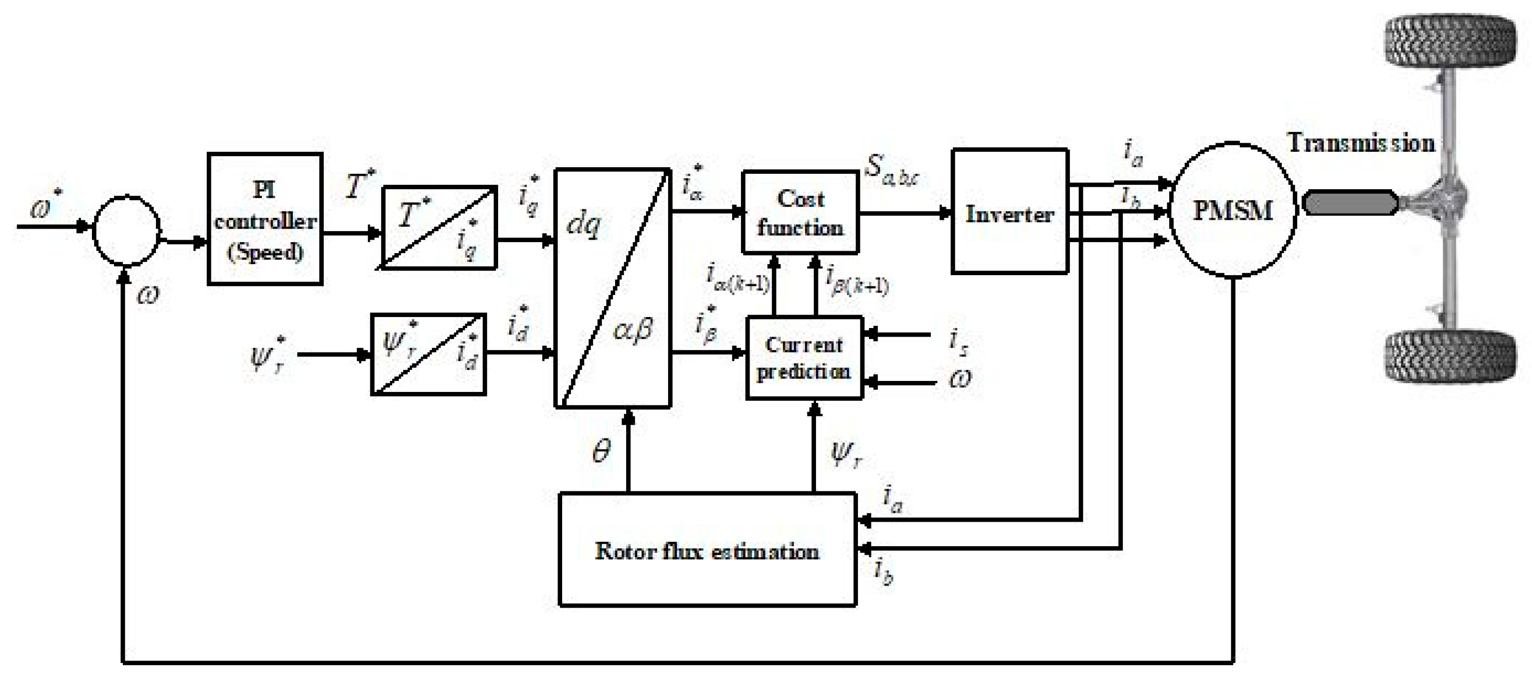
3. FCS-MPC Theory and Modeling

The block diagram for FCS-MPC is given in Figure 2. Model predictive control is not limited only to the application of motor control [28]. FCS-MPC is a method which involves:
  • Implementing a mathematical model for the system in consideration, which is used to predict the future values of the control variable;
  • Implementing a cost function to minimize error in the control variables.
In the case of motor control, FCS-MPC can be applied to any of the classical control strategies. In this paper, the cost function is used to minimize the error in id and iq values and it can be called an Model predictive Field Oriented Control MPFOC algorithm [29]. For the PMSM, the model implemented is used to predict the id and iq values for the next instant. The equations are given by:
i d ( k + 1 ) =   ( ( 1 ( R T s L ) ) i d ( k ) ) + ( T s W r i q ( k ) ) + ( v d ( k ) T s L )
i q ( k + 1 ) = ( ( 1 ( R T s L ) ) i q ( k ) )   ( T s W r i d ( k ) )   ( T s W r m )   + ( v q ( k ) T s L )
The cost function for this control utilizes the minimized square error type and is given by:
C o s t = ( i d   ( r e f ) i d ) 2 + ( i q   ( r e f ) i q ) 2 + ( T r e f   T m ) 2 + C m a x + S m i n
where id and iq are d and q axis currents, respectively, and Tm is the electromagnetic torque. The controller has a variable switching frequency since the switching states are decided based on the minimizing of cost function, and additional constraints are added to minimize the number of switching states, which is given by Smin. Cmax is the constraints to limit the maximum permissible dq currents in the motor.

4. Simulation Modeling and Demonstration

To demonstrate the effectiveness of the aforementioned algorithms, namely FOC and FCS-MPC, they were carried out on a two-wheeler vehicle having the motor parameters and vehicle specification shown in Table 2 and Table 3, respectively. The simulation was carried out in MATLAB/Simulink and results were validated using the OPAL-RT platform. A three-phase two-level Insulated Gate Bipolar Transistor IGBT-based voltage source inverter of rating 3 kW was utilized with space vector modulation. The switching frequency used was 5 kHz. The PI gain was selected with the help of response optimization in MATLAB and the gains are mentioned in Table 2. To analyze the two control strategies for EVs, two different scenarios were simulated in both cases:
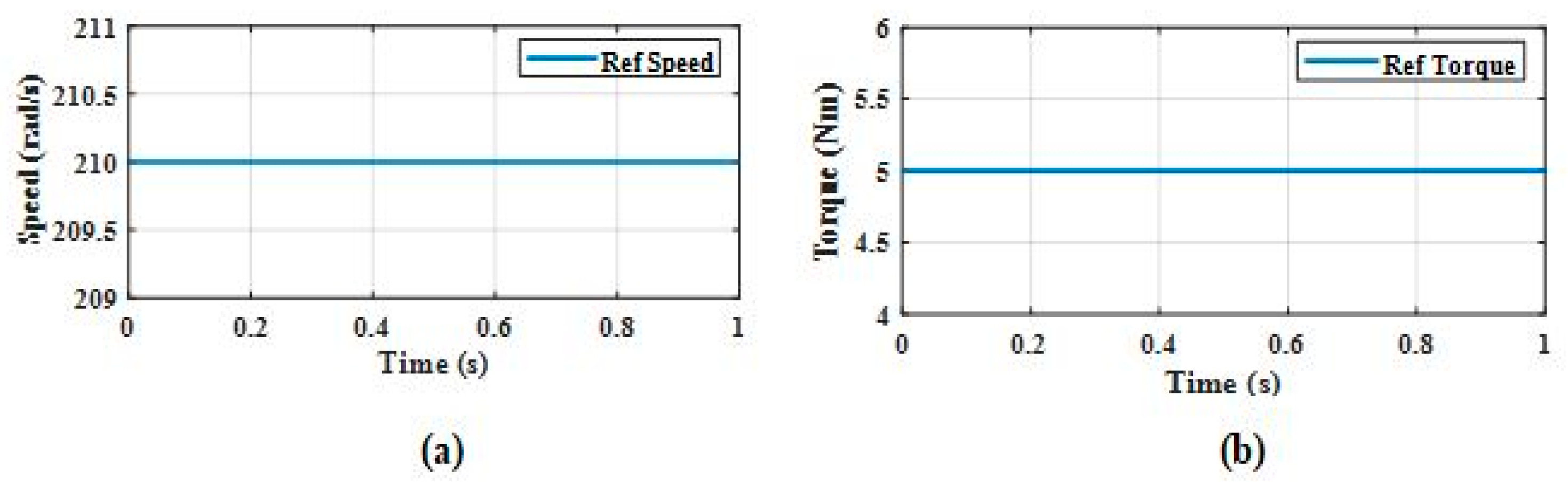
  • Best-Case Condition: Constant Speed and Constant Torque.
  • Worst-Case Condition: Variable Speed and Variable Torque.
When speaking in the context of any vehicle, an important aspect to test is whether the torque profile can hold steady over an entire range of speed profiles. Hence, torque profiles were generally taken to be constant, and to test the worst-case scenario, a step change was employed at a given instant to depict sudden loading change in the vehicle. The important steady-state aspect for torque profile is the torque ripples present in the output. The motor specification and vehicle specification used in this work are shown in Table 4 and Table 5.
For the speed profile, the control strategy must be tested for different conditions of operating speed. One of the most critical requirements is called cruising, wherein the speed of the vehicle is maintained at a constant over a given time. The cruising condition is essential to test the steady-state error for the speed so that the cruising speed is reliably attained and maintained.
Another essential requirement is constant acceleration since it quantifies how well the algorithm can track the changing speed of the vehicle, and this phase is generally used to test the dynamic characteristics. Likewise, speed reversal is another vital part of the speed profile since the control strategy must also respond to a sudden change in the direction of movement.
In order to evaluate the performance of the motor for the EV, the aforementioned drive conditions were incorporated as two cases. In the first case, the motor was tested for cruising at rated conditions. In the second case, the motor was tested for speed reversal, acceleration, and cruising. The reference speed and torque graphs for both approaches are as follows.
  • Case 1: Constant Speed and Constant Torque
In Case 1, the machine is made to operate at a constant speed and torque value, both of which are the machine rated values. The rated speed is 2000 rpm, i.e., approx. 210 rad/s, and the torque is 5 Nm. Figure 3a shows the reference speed to the PMSM, while Figure 3b shows the reference load torque.
  • Case 2: Variable Speed and Variable Torque
In Case 2, the machine is operated under the worst-case condition when being used in an EV. This is the condition of varying speed and varying torque. For the speed profile, the machine is made to start at −210 rad/s, and after some time, it gradually rises to 210 rad/s to depict the accelerating condition. For varying torque, a step change is given t = 0.1 s from 1 to 5 Nm and is stepped down to 1 Nm at t = 0.3 s. Figure 4a shows the reference speed to the PMSM, while Figure 4b shows the reference load torque.

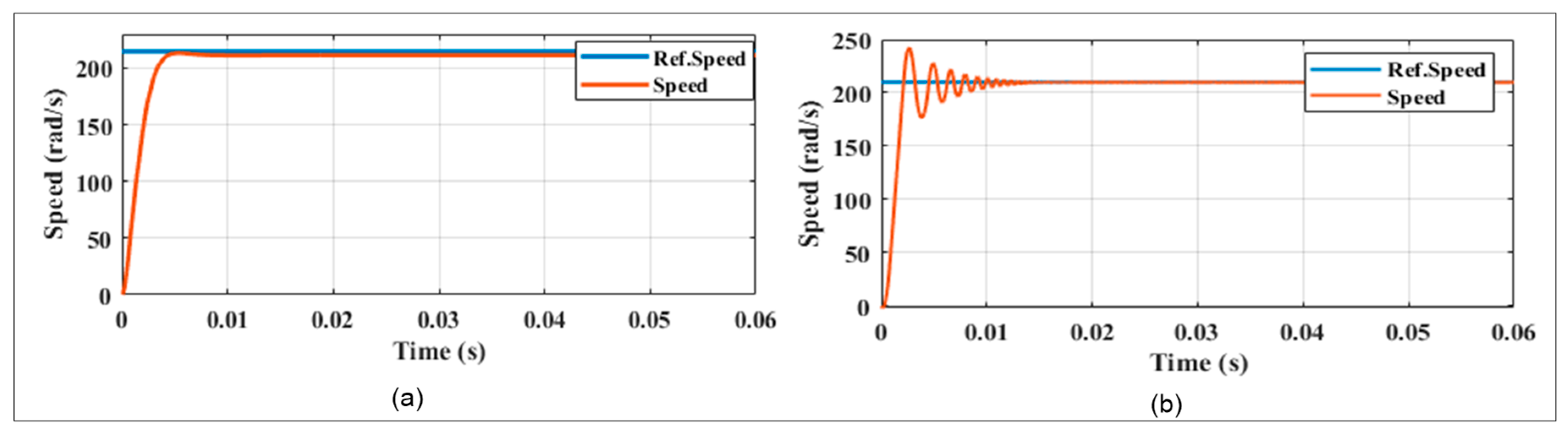
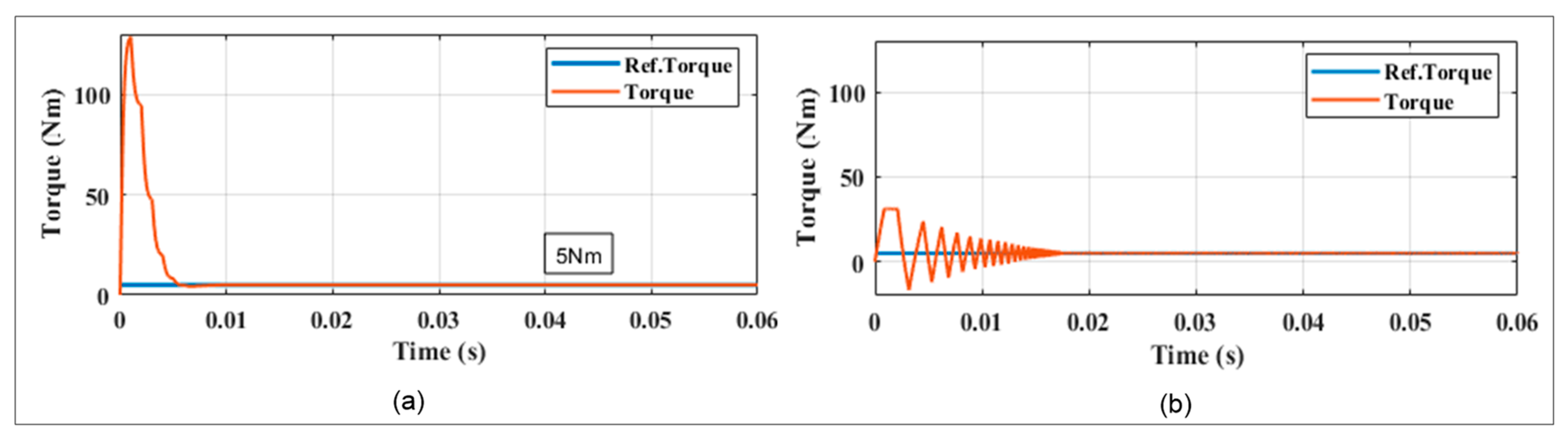
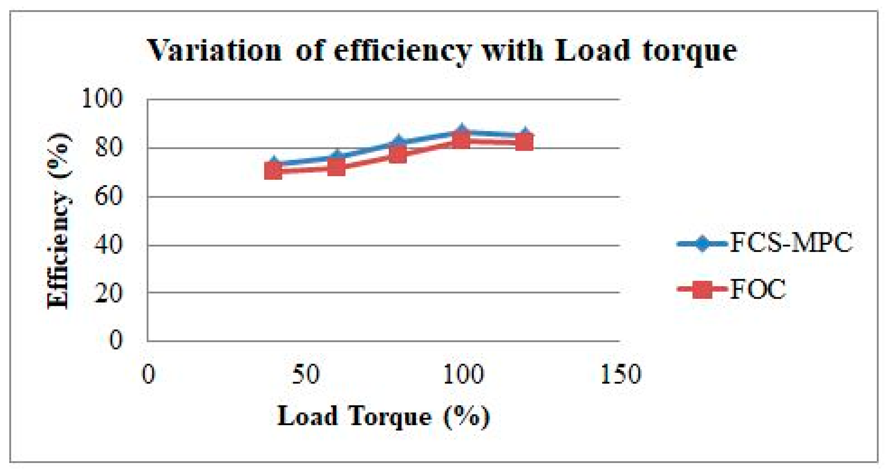
5. Results and Discussion

5.1. Results for Case 1

Figure 5a, Figure 6a, Figure 7a and Figure 8a give the motor speed, electromagnetic torque, direct and quadrature axis currents, and stator currents, respectively, for FOC when input waveforms are given according to Case 1. Figure 5b, Figure 6b, Figure 7b and Figure 8b give the motor speed, electromagnetic torque, direct and quadrature axis currents, and stator currents, respectively, for FCS-MPC when input waveforms are given according to Case 1.
When the rated speed and torque are applied to the PMSM, the FCS-MPC results are better than the FOC results in both Case 1. The FCS-MPC takes 0.015 s to reach a steady state. Even though FOC is quicker (<0.01 s) to reach a steady state, it has a steady-state error of 2%. Similarly, by observing the electromagnetic torque results shown in Figure 6, FOC is observed to have an overshoot that is two times more than that of the FCS-MPC. The same pattern is observed in direct and quadrature axis and stator phase currents for both FOC and FCS-MPC, which are shown in Figure 7 and Figure 8, respectively. From the results of Case 1, we can infer that FCS-MPC has smaller overshoot and better steady-state error when compared with the FOC scheme.

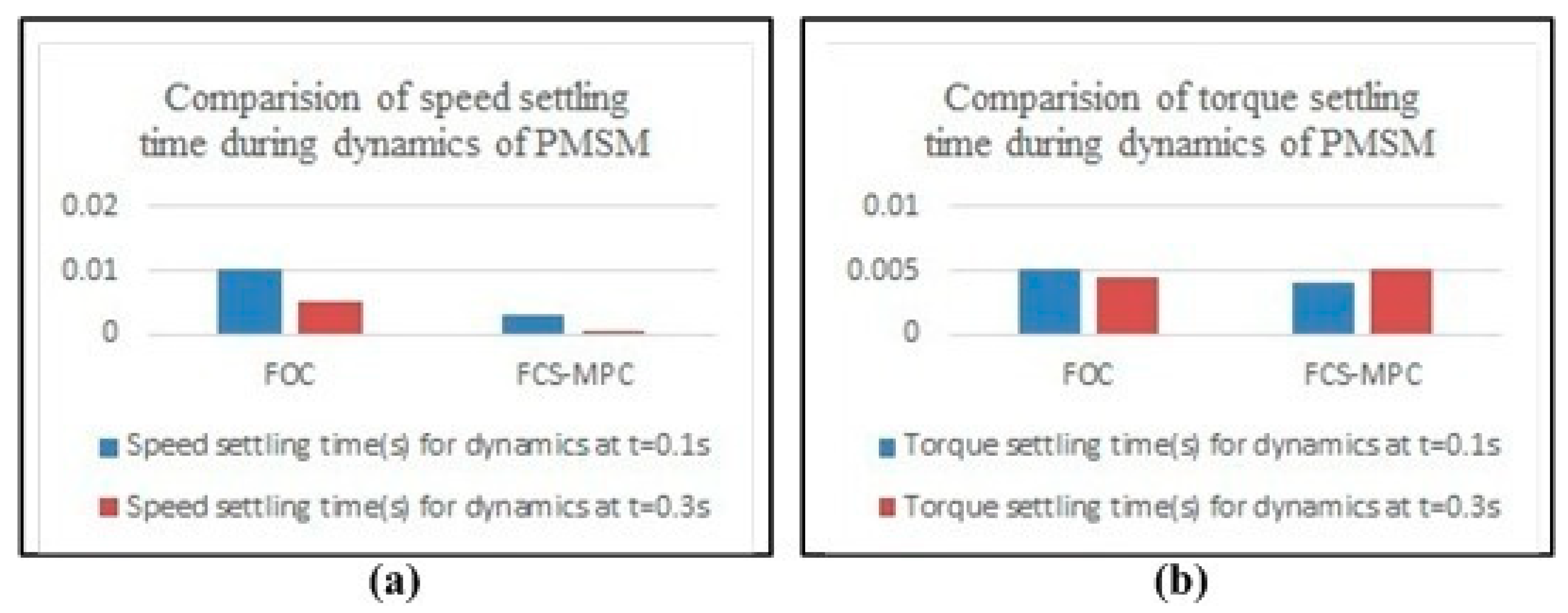
5.2. Results for Case 2

Figure 9a, Figure 10a, Figure 11a and Figure 12a respectively give the Motor speed, electromagnetic torque, direct & quadrature axis currents and stator phase currents for FOC when input waveforms are given according to Case 2. Figure 9b, Figure 10b, Figure 11b and Figure 12b respectively give the Motor speed, electromagnetic torque, direct & quadrature axis currents and stator phase currents for FCS-MPC when reference waveforms are given according to Case 2.
In Case 2, when there is step-change applied to torque and speed in between 0.1 and 0.3 s in Figure 9, during the transition from negative speed to positive speed, FCS-MPC follows the reference speed perfectly, but FOC has a slight delay during the transition. To calculate and compare the steady-state characteristics of both of the control strategies, the error in speed is calculated in root mean square speed error (RMSSE) and the torque ripples in root mean square torque error (RMSTE). The formulas for both are:
RMSSE = 1 N k = 1 N ( ω r a v g ω r ( k ) ) 2
RMSTE = 1 N k = 1 N ( T e r e f T e ( k ) ) 2
For dynamic characteristics, we consider the maximum overshoot value from the reference value and the settling time, which is the time taken to reach the steady-state value. It must also be noted that the dynamic characteristics can only be calculated when there is a change at any point in the profile of the speed and the torque. Hence, the values are calculated at the instant the input changes.

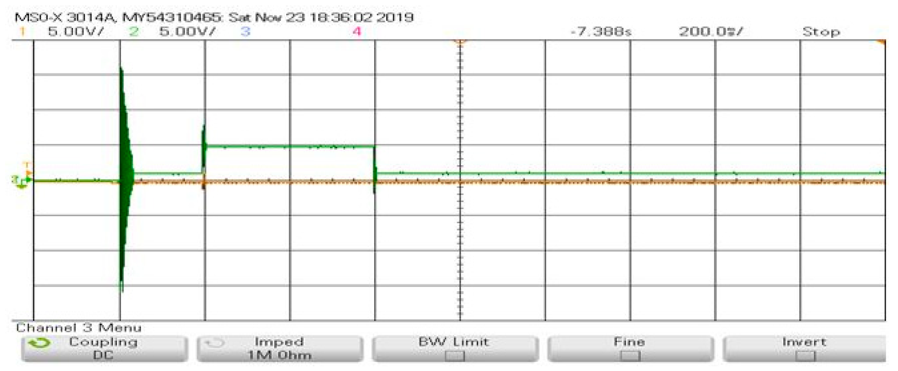
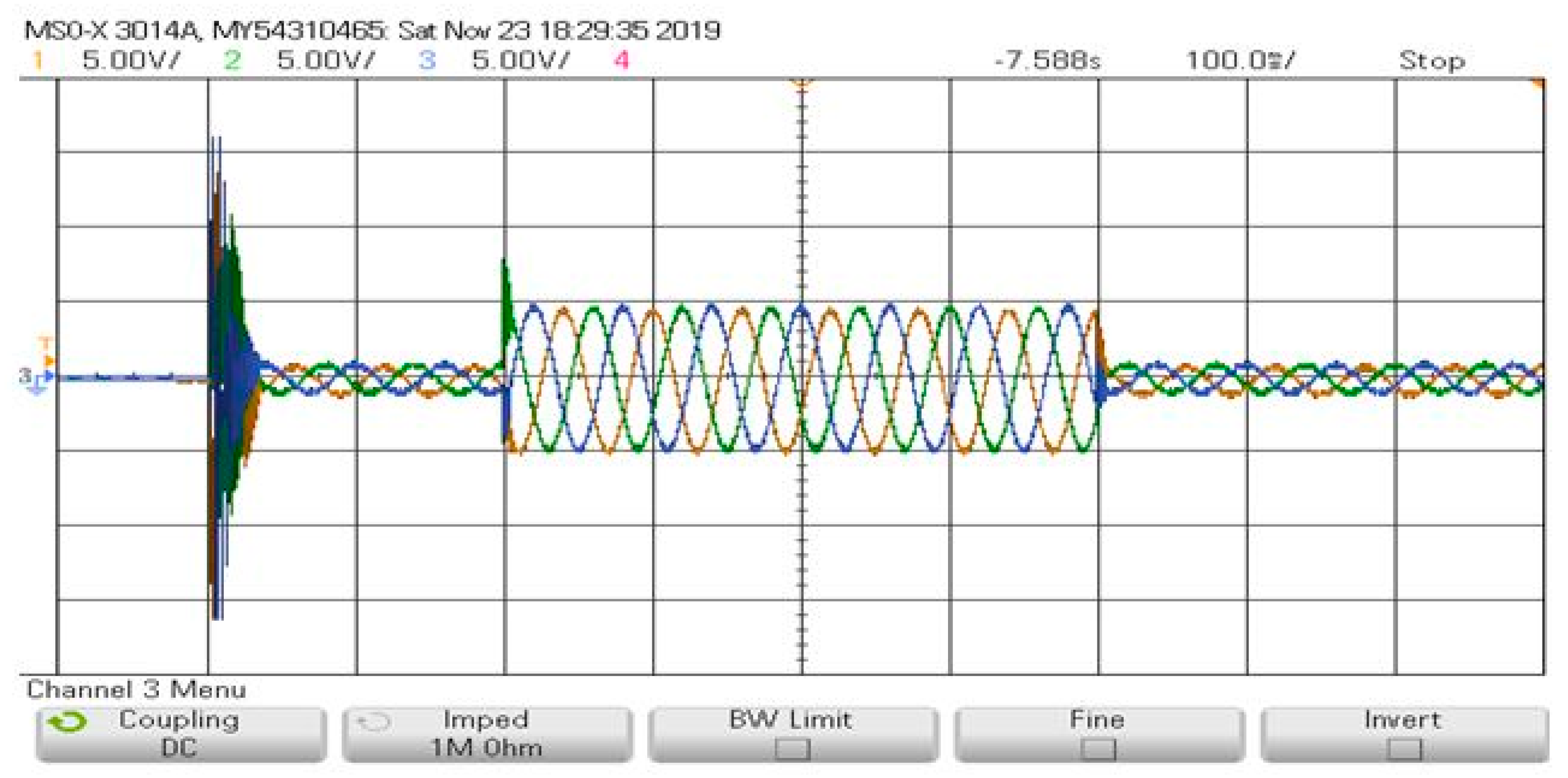
5.3. Real-Time Operating Results Using OPAL-RT

Figure 13, Figure 14, Figure 15 and Figure 16 give the motor speed, electromagnetic torque, direct and quadrature axis currents, and stator currents, respectively, for FCS-MPC in a real-time environment using OPAL-RT when reference waveforms are given according to Case 1. Figure 17, Figure 18, Figure 19 and Figure 20 show the same for Case 2. The obtained real-time results using OPAL-RT are similar to simulation results. Figure 21 shows how the efficiency varies with the change in load torque and the proposed FCS-MPC gives better efficiency compared to FOC.
As can be observed from Table 6, the steady-state error is significantly lower for the FCS-MPC scheme. The torque ripple percentage is 3% less in FCS-MPC as compared with the FOC algorithm. In Table 4, we can observe that the FCS-MPC has 14% and 6% less speed error and torque ripple, respectively. This occurs since the FCS-MPC algorithm has a variable switching frequency. The switching frequency is variable since the algorithm tries to minimize the cost function as quickly as possible and the switching states may deviate small values away from the reference. The cost function implemented here, however, also has a term to minimize the number of switching states, so the steady-state error is minimized here as well.
However, the use of the cost function in place of PI controllers produces reduced error comparatively in the dynamic characteristics of both the speed and torque profiles. The additional PI controller used in FOC hampers the dynamic performance of the system due to its dependence upon the gains of these individual controllers. Since both algorithms have their own pros and cons, we can analyze which algorithm would be better suited for which situation. When discussing from the perspective of EVs, both the torque and speed profiles can vary over a given period. It is also important to ensure that the vehicle can attain the reference speed quickly since the speed can be changed instantaneously. This mimics the second case of simulation in this paper.
Figure 22a,b shows the settling time during the dynamics of PMSM for FOC and FCS-MPC. From this figure we can infer that the FCS-MPC outperforms the FOC during dynamic condition in speed and torque by settling down faster. Thus, in the above case, it can be concluded that the FCS-MPC algorithm has many more advantages over the FOC algorithm. In addition to having a better dynamic response, the cost function can be modified to minimize other parameters. However, in the condition of cruising, there are no changes in the input over the time period and the emphasis should be more on the steady-state characteristics, mainly the speed steady-state error. While the error is lower in FCS-MPC compared to FOC, it is negligible enough to avoid in this case. On the other hand, there are more torque ripples in FOC and we can conclude that FCS-MPC is a better algorithm compared to FOC in the cruising condition for vehicles over a time period as well. It is concluded, in the aforementioned cases, that FCS-MPC is the best controller for a PMSM-driven vehicle. As a further addition to strengthen the analysis, a WLTP drive cycle was used to evaluate the FCS-MPC-driven PMSM. Figure 23 shows the WLTP drive cycle given as the reference speed for 750 s and that the PMSM is able to accurately track the reference speed. This drive cycle test was performed to evaluate the suitability of the power train for the lightweight vehicle. From the test, it is evident that the FCS-MPC algorithm is able to accurately perform acceleration, cruising, sudden braking, and reversal according to the requirement. Based upon the analysis carried out so far, we can conclude that the PMSM drives are the main candidates for commercial electric two-wheelers. Since the torque ripple is a critical parameter to decide the vibrations and jerks during travel, it is important to limit this at a lower value. From the results, it is evident that the paper has contributed a solid conclusion to freeze on the control strategy of the PMSM drive from the EV perspective, enabling smooth travel.

6. Conclusions

Two promising control strategies for PMSM drive were designed and implemented. The designed PMSM drive has been analyzed for different drive cycles which explore the real picture of the control logistics from the EV perspective. The main contribution of this work is the identification of an optimal and promising control methodology for commercial electric cars which meets the need of the hour. From the simulation results, it has been proven that FCS-MPC outperforms FOC in terms of less torque ripples and better dynamic response. Since the aforementioned parameters have a considerable effect on the EV dynamics, the FCS-MPC algorithm has been concluded as an optimal control methodology for electric bikes. As a next step to validate the simulation results, real-time implementation was performed using the OPAL-RT platform. A WLTP drive cycle was used to confirm the aforementioned analysis that the FCS-MPC-controlled PMSM is able to accurately track speed. As the world begins to adopt EVs as a commercial mode of transport, it is important to analyze the different control strategies for motors and adopt suitable techniques for different EVs. The dynamic performance parameters were evaluated for sudden acceleration given a constant torque and a slow acceleration from a negative speed to a positive speed in a variable torque condition (step change), taken as two scenarios. In addition, testing of the FCS-MPC-controlled PMSM in a WLTP drive cycle proved the suitability of the same for EV applications. The paper has successfully analyzed in detail the different aspects of both the promising control strategies and has provided different drive cycle performances from EV aspects and also presented a quantitative analysis to defend the statements. The future scope of this work could be to work on the cost function to achieve better results.

Author Contributions

Conceptualization, Formal analysis; Supervision R.S.W. and U.S.; Investigation, Validation, Methodology, C.S.R.G.; Writing, review & editing, A.M. and C.A. All authors have read and agreed to the published version of the manuscript.

Funding

Research received no funding.

Acknowledgments

The authors would like to acknowledge the support of Prince Sultan University for paying the Article Processing Charge (APC) of this publication. The authors would like to express their sincere gratitude to the Vellore Institute of Technology, Vellore, for providing the infrastructure for carrying out the work. They would also like to thank the Renewable Energy research lab, College of Engineering, Prince Sultan University, Riyadh, Saudi Arabia, for providing technical inputs.

Conflicts of Interest

The authors declare no conflict of interest.

References

  1. Younesi, A.; Tohidi, S.; Feyzi, M.R.; Baradarannia, M. An improved nonlinear model predictive direct speed control of permanent magnet synchronous motors. Int. Trans. Energy Syst. 2018, 28, e2535. [Google Scholar] [CrossRef]
  2. Sultana, W.R.; Sahoo, S.K.; Saikiran, K.S.; Reddy, G.R.; Reddy, P.H. A computationally efficient finite state model predictive control for cascaded multilevel inverter. Ain Shams Eng. J. 2016, 7, 567–578. [Google Scholar] [CrossRef] [Green Version]
  3. Amezquita-Brooks, L.; Liceaga-Castro, J.; Liceaga-Castro, E. Speed and position controllers using indirect field-oriented control: A classical control approach. IEEE Trans. Ind. Electron. 2013, 61, 1928–1943. [Google Scholar] [CrossRef]
  4. Kiran, K.; Das, S.; Singh, D. Model predictive field oriented speed control of brushless doubly-fed reluctance motor drive. In Proceedings of the International Conference on Power, Instrumentation, Control and Computing (PICC), Thrissur, India, 18–20 January 2018; pp. 1–6. [Google Scholar]
  5. Liu, T.; Chen, G.; Li, S. Application of Vector Control Technology for PMSM Used in Electric Vehicles. Open Autom. Control Syst. J. 2014, 6, 1334–1341. [Google Scholar] [CrossRef]
  6. Li, N.; Ming, Y.; Xianguo, G.; Dianguo, X. A comparative study of model predictive current control and FOC for PMSM. In Proceedings of the 17th International Conference on Electrical Machines and Systems (ICEMS), Hangzhou, China, 22 October 2014; pp. 3143–3147. [Google Scholar]
  7. Niu, F.; Wang, B.; Babel, A.S.; Li, K.; Strangas, E.G. Comparative evaluation of direct torque control strategies for permanent magnet synchronous machines. IEEE Trans. Power Electron. 2015, 31, 1408–1424. [Google Scholar] [CrossRef]
  8. Liu, X.; Chen, H.; Zhao, J.; Belahcen, A. Research on the performances and parameters of interior PMSM used for electric vehicles. IEEE Trans. Ind. Electron. 2016, 63, 3533–3545. [Google Scholar] [CrossRef]
  9. Wu, S.; Zhang, J. A robust adaptive control for permanent magnet synchronous motor subject to parameter uncertainties and input saturations. J. Electr. Eng. Technol. 2018, 13, 2125–2133. [Google Scholar]
  10. Zhang, Y.; Xia, B.; Yang, H. Performance evaluation of an improved model predictive control with field oriented control as a benchmark. IET Electr. Power Appl. 2017, 11, 677–687. [Google Scholar] [CrossRef]
  11. Adamopoulos, N.K.; Karamountzou, F.A.; Sarigiannidis, A.G.; Kladas, A.G. Comparison of field oriented versus model predictive torque control techniques for monitoring interior PM traction motor over wide speed range. In Proceedings of the 2017 IEEE 11th International Symposium on Diagnostics for Electrical Machines, Power Electronics and Drives (SDEMPED), Tinos, Greece, 29 August–1 September 2017. [Google Scholar]
  12. Yang, J.; Mao, Y.; Chen, Y. Sensorless control of permanent magnet synchronous motors with compensation for parameter uncertainty. J. Electr. Eng. Technol. 2017, 12, 1166–1176. [Google Scholar] [CrossRef] [Green Version]
  13. Liu, Q.; Hameyer, K. Torque ripple minimization for direct torque control of PMSM with modified FCSMPC. IEEE Trans. Ind. Appl. 2016, 52, 4855–4864. [Google Scholar] [CrossRef]
  14. Ben Salem, F.; Feki, M. An Improved DTC Induction Motor for Electric Vehicle Propulsion: An Intention to Provide a Comfortable Ride. Solving Transp. Probl. Towards Green Logist. 2019, 16, 185–201. [Google Scholar]
  15. Justo, J.J.; Mwasilu, F.; Kim, E.K.; Kim, J.; Choi, H.H.; Jung, J.W. Fuzzy model predictive direct torque control of IPMSMs for electric vehicle applications. IEEE/ASME Trans. Mechatron. 2017, 22, 1542–1553. [Google Scholar] [CrossRef]
  16. de Castro, A.G.; de Andrade Pereira, W.C.; de Oliveira, C.M.; de Almeida, T.E.; Guazzelli, P.R.; de Almeida Monteiro, J.R.; de Oliveira Junior, A.A. Finite control-set predictive power control of BLDC drive for torque ripple reduction. IEEE Latin Am. Trans. 2018, 16, 1128–1135. [Google Scholar] [CrossRef]
  17. Wang, L.; Wang, X. Finite-control-set model predictive control for eight-switch three-phase NPC converters. IEEJ Trans. Electr. Electron. Eng. 2019, 14, 105–115. [Google Scholar] [CrossRef] [Green Version]
  18. Abbaszadeh, A.; Khaburi, D.A.; Rodríguez, J. Predictive control of permanent magnet synchronous motor with non-sinusoidal flux distribution for torque ripple minimisation using the recursive least square identification method. IET Electr. Power Appl. 2017, 11, 847–856. [Google Scholar] [CrossRef]
  19. Xia, C.; Deng, W.; Shi, T.; Yan, Y. Torque ripple minimization of PMSM using parameter optimization based iterative learning control. J. Electr. Eng. Technol. 2016, 11, 425–436. [Google Scholar] [CrossRef]
  20. Lalezar, G.; Nejad, S.M.; Mojiri, M. Enhancing surface-mounted permanent magnet synchronous motor drives in steady and transient states through improved MPCC method. Int. Trans. Electr. Energy Syst. 2020, 30, e12331. [Google Scholar] [CrossRef]
  21. Li, Y.; Zhang, P.; Hang, J.; Ding, S.; Liu, L.; Wang, Q. Comparison of dynamic characteristics of field oriented control and model predictive control for permanent magnet synchronous motor. In Proceedings of the 2018 13th IEEE Conference on Industrial Electronics and Applications (ICIEA), Wuhan, China, 31 May–2 June 2018; pp. 2431–2434. [Google Scholar]
  22. Tang, M.; Zhuang, S. On speed control of a permanent magnet synchronous motor with current predictive compensation. Energies 2019, 12, 65. [Google Scholar] [CrossRef] [Green Version]
  23. Shu, H.; Guo, C.; Song, Y.; Chen, X.; Luo, S. Design of model predictive controllers for PMSM drive system based on the extended Kalman filter observer. Int. J. Electr. Hybrid Veh. 2019, 11, 378–394. [Google Scholar] [CrossRef]
  24. He, Y.; Xu, Y. Dynamic Model Predictive Current Control Based on Deviation for Permanent Magnet Synchronous Motor. In Proceedings of the 2019 IEEE 28th International Symposium on Industrial Electronics (ISIE), Vancouver, BC, Canada, 12–14 June 2019; pp. 313–317. [Google Scholar]
  25. Zaky, M.S.; Morsi, M.A.; Shokrallah, S.S. High dynamic performance of interior permanent magnet synchronous motor drives based on feed-forward load torque compensator. Electr. Power Compon. Syst. 2013, 41, 235–251. [Google Scholar] [CrossRef]
  26. Yunfei, L.; Chengning, Z. A comparative experimental analysis of PMSM between deadbeat prediction current control and field-oriented control. Energy Procedia 2019, 158, 2488–2493. [Google Scholar] [CrossRef]
  27. Lara, J.; Xu, J.; Chandra, A. Effects of rotor position error in the performance of field-oriented-controlled PMSM drives for electric vehicle traction applications. IEEE Trans. Ind. Electron. 2016, 63, 4738–4751. [Google Scholar] [CrossRef]
  28. Razia Sultana, W.; Sahoo, S.K. Finite control set model predictive current control for a cascaded multilevel inverter. J. Electr. Eng. Technol. 2016, 11, 1674–1683. [Google Scholar] [CrossRef] [Green Version]
  29. Wang, F.; Mei, X.; Tao, P.; Kennel, R.; Rodriguez, J. Predictive field-oriented control for electric drives. Chin. J. Electr. Eng. 2017, 3, 73–78. [Google Scholar]
Figure 1. Block diagram of a field-oriented control (FOC)-controlled permanent magnet synchronous motor (PMSM) driving an electric vehicle (EV).
Wevj 12 00041 g001
Figure 2. Block diagram of the proposed finite control set model predictive control (FCS-MPC) algorithm-controlled PMSM for driving an EV.
Wevj 12 00041 g002
Figure 3. (a) Reference speed and (b) reference Torque.
Wevj 12 00041 g003
Figure 4. (a) Reference speed and (b) reference Torque.
Wevj 12 00041 g004
Figure 5. Motor speed for (a) FOC and (b) FCS-MPC.
Wevj 12 00041 g005
Figure 6. Electromagnetic torque for (a) FOC and (b) FCS-MPC.
Wevj 12 00041 g006
Figure 7. Direct and quadrature axis currents for (a) FOC and (b) FCS-MPC.
Wevj 12 00041 g007
Figure 8. Stator phase currents for (a) FOC and (b) FCS-MPC.
Wevj 12 00041 g008
Figure 9. Motor speed for (a) FOC and (b) FCS-MPC.
Wevj 12 00041 g009
Figure 10. Electromagnetic torque for (a) FOC and (b) FCS-MPC.
Wevj 12 00041 g010
Figure 11. Direct and quadrature axis currents for (a) FOC and (b) FCS-MPC.
Wevj 12 00041 g011
Figure 12. Stator phase currents for (a) FOC and (b) FCS-MPC.
Wevj 12 00041 g012
Figure 13. Motor speed for FCS-MPC.
Wevj 12 00041 g013
Figure 14. Electromagnetic torque for FCS-MPC.
Wevj 12 00041 g014
Figure 15. Direct and quadrature axis currents for FCS-MPC.
Wevj 12 00041 g015
Figure 16. Stator phase currents for FCS-MPC.
Wevj 12 00041 g016
Figure 17. Speed profile for FCS-MPC.
Wevj 12 00041 g017
Figure 18. Electromagnetic torque profile for FCS-MPC.
Wevj 12 00041 g018
Figure 19. Direct and quadrature axis currents for FCS-MPC.
Wevj 12 00041 g019
Figure 20. Stator phase currents for FCS-MPC.
Wevj 12 00041 g020
Figure 21. Variation of efficiency with load torque for FOC and FCS-MPC.
Wevj 12 00041 g021
Figure 22. (a,b) Speed and torque settling time for FOC and FCS-MPC.
Wevj 12 00041 g022
Figure 23. Performance of FCS-MPC-controlled PMSM for a WLTP drive cycle.
Wevj 12 00041 g023
Table 1. Nomenclature.
ParameterValue
u a b c Stator three phase voltages
u d q Direct and Quadrature axis voltages
i d q Direct and Quadrature axis currents
m Rotor flux linkages
p Number of pole pairs
v q ( k ) present value of Quadrature axis voltage
i d ( k ) present value of Direct axis current
i q ( k ) present value of Quadrature axis current
i d   ( r e f ) Reference value of Direct axis current
i q   ( r e f ) Reference value of Quadrature axis current
T e Electro magnetic Torque
R Stator restistance per phase
L Stator inductance per pahse
T s Sampling time
v d ( k ) present value of Direct axis voltage
i d ( k + 1 ) Future value of Direct axis current
i q ( k + 1 ) Future value of Quadrature axis current
W r Angular velocity of the rotor
T r e f Reference Torque
C m a x Maximum permissible dq currents for motor
S m i n Switching state minimization
WLTPWorldwide Harmonized Light Vehicles Test Procedure
Table 2. Specifications of the PMSM model.
ParameterValue
Rotor TypeSalient Pole
Stator Resistance per phase0.02 Ω
Direct and Quadrature Axis Inductance1.7 and 3.2 mH
Flux Linkage in Airgap0.2205 V.s
No. of Pole Pairs4
Rated Torque8 Nm
Rated Speed2000 rpm
Rated Power2.8 kW
PI Controller 1KP = 0.1, KI = 0.1
PI Controller 2KP = 7.74, KI = 26.84
PI Controller 3KP = 7.74, KI = 26.84
Table 3. Vehicle model—Two-wheeler.
ParameterValue
Weight125 kg
Rolling resistance coefficient (Crr)0.01
Drag coefficient (Cd)0.2
Frontal area0.85 square meters
Wheel radius0.16 m
Air density1.22 kg/meter cube
Velocity75 Kmph
Table 4. Steady-state comparison for Case 2.
Steady State CharacteristicFOCFCS-MPC
Speed SSE (%)0.15 −0.003
Torque Ripple (%)0.20.14
Table 5. Dynamic characteristic comparison for Case 2.
Operating ConditionDynamic CharacteristicFOCFCS-MPC
Ramp change in speed at t = 0.1 sSpeed Undershoot (%)
Speed Overshoot (%)
15
0
0
0
Speed Settling Time (s)0.010.005
Ramp change in speed at t = 0.3 sSpeed Overshoot (%)0.010
Speed Settling Time (s)0.0030.0001
Torque step increase from 1 to 5 NmTorque Settling Time (s)0.0050.004
Torque step decrease from 5 to 1 NmTorque Settling Time (s)0.00450.005
Table 6. Steady-state comparison for Case 1.
Steady State CharacteristicFOCFCS-MPC
Speed SSE (%)20.004
Torque Ripple (%)0.150.12
Publisher’s Note: MDPI stays neutral with regard to jurisdictional claims in published maps and institutional affiliations.

