
Safety Design and Engineering Solution of Fuel Cell Powered Ship in Inland Waterway of China


China Classification Society, Beijing 100007, China
*
Author to whom correspondence should be addressed.
World Electr. Veh. J. 2021, 12(4), 202; https://0-doi-org.brum.beds.ac.uk/10.3390/wevj12040202
Submission received: 1 September 2021
/
Revised: 27 September 2021
/
Accepted: 13 October 2021
/
Published: 19 October 2021
(This article belongs to the Special Issue Towards Intelligent E-Mobility—Selected Papers from The 34th International Electric Vehicles Symposium and Exhibition (Nanjing, China))
Abstract
:From the perspective of risk control, when hydrogen fuel and fuel cells are used on ships, there is a possibility of low-flash fuel leakage, leading to the risk of explosion. Since the fuel cell space (cabin for fuel cell installations) is an enclosed space, any small amount of leakage must be handled properly. In ship design, area classification is a method of analyzing and classifying the areas where explosive gas atmospheres may occur. If the fuel cell space is regarded as a hazardous area, all the electrical devices inside it must be explosion-proof type, which will make the ship’s design very difficult. This paper takes a Chinese fuel cell powered ship as an example to analyze its safety. Firstly, the leakage rates of fuel cell modules, valves, and connectors are calculated. Secondly, the IEC60079-10-1 algorithm is used to calculate the risk level of the fuel cell space. Finally, the ship and fuel cells are optimized and redesigned, and the risk level of the fuel cell space is recalculated and compared. The result shows that the optimized fuel space risk level could be reduced to the level of the non-hazardous zone.
1. Introduction
International shipping carries about 90% of the trade in the global shipping supply chain. At present, the global international shipping fleet has reached more than 90,000 ships, but the ship’s energy is still based on petroleum-based fuel, resulting in a large number of harmful gas and greenhouse gas (GHG) emissions. In the context of the global response to climate change, the shipping industry is facing increasing pressure from international greenhouse gas emissions. In April 2018, IMO (International Maritime Organization) adopted an initial strategy for reducing GHG, setting a long-term goal of reducing GHG emissions from the global shipping industry by at least 50% from 2008 levels by 2050. The EU, Japan, and Germany have all introduced hydrogen energy utilization policies [1,2,3], which put forward important and urgent requirements for the low-carbon development of the shipping industry.
In the field of hydrogen fuel cell vehicles, projects in Europe and the United States have demonstrated the advantages of hydrogen fuel cells, including short refueling times, safe and reliable power trains, and long-distance driving [4,5]. Both battery power and hydrogen fuel cell power are limited by charging or hydrogen refueling facilities. Hydrogen fuel cells are more likely to be used in marine power systems because fuel cell power systems have significant advantages over lithium battery power systems in terms of distance running and refueling time [6].
From a ship’s point of view, hydrogen can react with oxygen in the air to produce water through fuel cells, without producing GHG and air pollutants such as PM (particulate matter), SOX (sulfur oxide), and NOX (nitrogen oxide). It is also a true “zero-emission” alternative energy source for ships, but its application in ships is still in the preliminary exploratory stage.
However, at present, there are many studies on the safety of hydrogen, but few on the safety of ships. Japan has laws and regulations on hydrogen safety. For example, the hydrogen fuel cell motorcycle regulations specify the capacity, type, and protection technical requirements for hydrogen bottles [7]. Various authors have suggested methods for calculating the consequences of hydrogen explosions [8,9,10,11,12]. Ustolin et al. focused on the integrity loss of hydrogen equipment [13]. Various authors focused on the application of several fuel cell powered ship projects in Europe, put forward different design schemes, and compared the efficiency and economy [14,15]. Vogler, F. summarized several cases of fuel cell powered ships and proposed some general measures to prevent hydrogen fuel leakage; however, this researcher did not analyze the leakage of fuel cell modules [16]. Therefore, this paper mainly studies the impact of leakage from fuel cell modules, valves, and connectors on the fuel cell space. The release rate of leakage was estimated by quantitative calculation, and the effectiveness of existing ventilation under these leakage conditions was calculated by referring to the algorithm recommended by IEC 60079-10-1 [17]. Finally, taking a fuel cell powered ship funded by the Ministry of Industry and Information Technology of China as an example, the ship cabin layout, fuel cell module, and ventilation are optimized and analyzed to control the risk level of the fuel cell space and reduce the difficulty of ship design.
2. Features of the Pilot Fuel Cell Powered Ship
2.1. Development of Fuel Cell Powered Ships
The early fuel cell powered ship projects aimed to explore the feasibility of using zero-emission ships in environmentally sensitive areas and to put safety principles into practice to promote wider adoption of this technology in the shipping industry. Therefore, compressed hydrogen storage and PEMFC (Proton Exchange Membrane Fuel Cell) have been selected, and the technology is mature. With the development of high-temperature fuel cell technology in recent years, its efficiency is getting higher, the material cost is getting lower and lower, and the requirement for hydrogen purity is decreasing [18]. LNG and methanol are easier to store on ships than hydrogen because of their higher volumetric energy density [19]. As a result, many pilot projects have started using LNG and methanol as well as high-temperature fuel cells. There have been more than 20 fuel cell powered ship projects since 2005 [20], some of which are listed in Table 1.
A ship’s main source of electricity is the critical equipment, which affects the ship’s safety equipment (e.g., navigation, communication, and control devices) and the crew’s living conditions (e.g., lighting, food refrigeration, ventilation, and freshwater equipment). The dynamic performance of fuel cells is not suitable for use alone [21]. Therefore, the hybrid power system composed of fuel cells, and batteries or generators is commonly used for fuel cell powered ships.
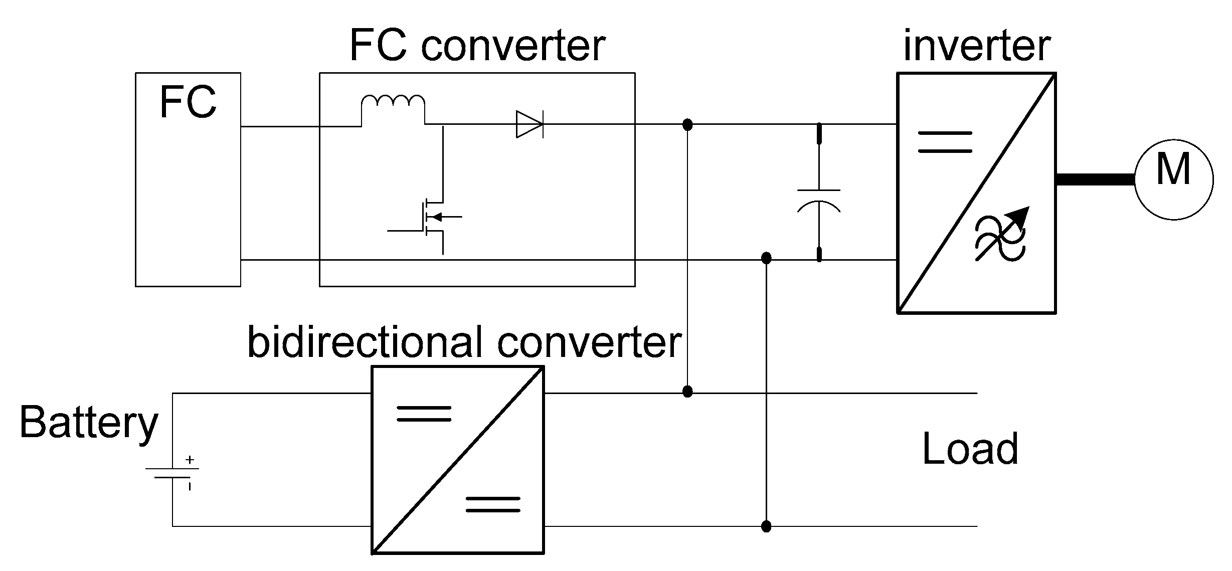
The Zemship project was an early project, the ship’s main power sources were fuel cells, and the fuel cells connected to the DC-bus via boost converters. The batteries were also connected to the DC bus via bi-directional converters. During navigation, the batteries can be used as a power source, or be recharged by the fuel cells, as shown in Figure 1.
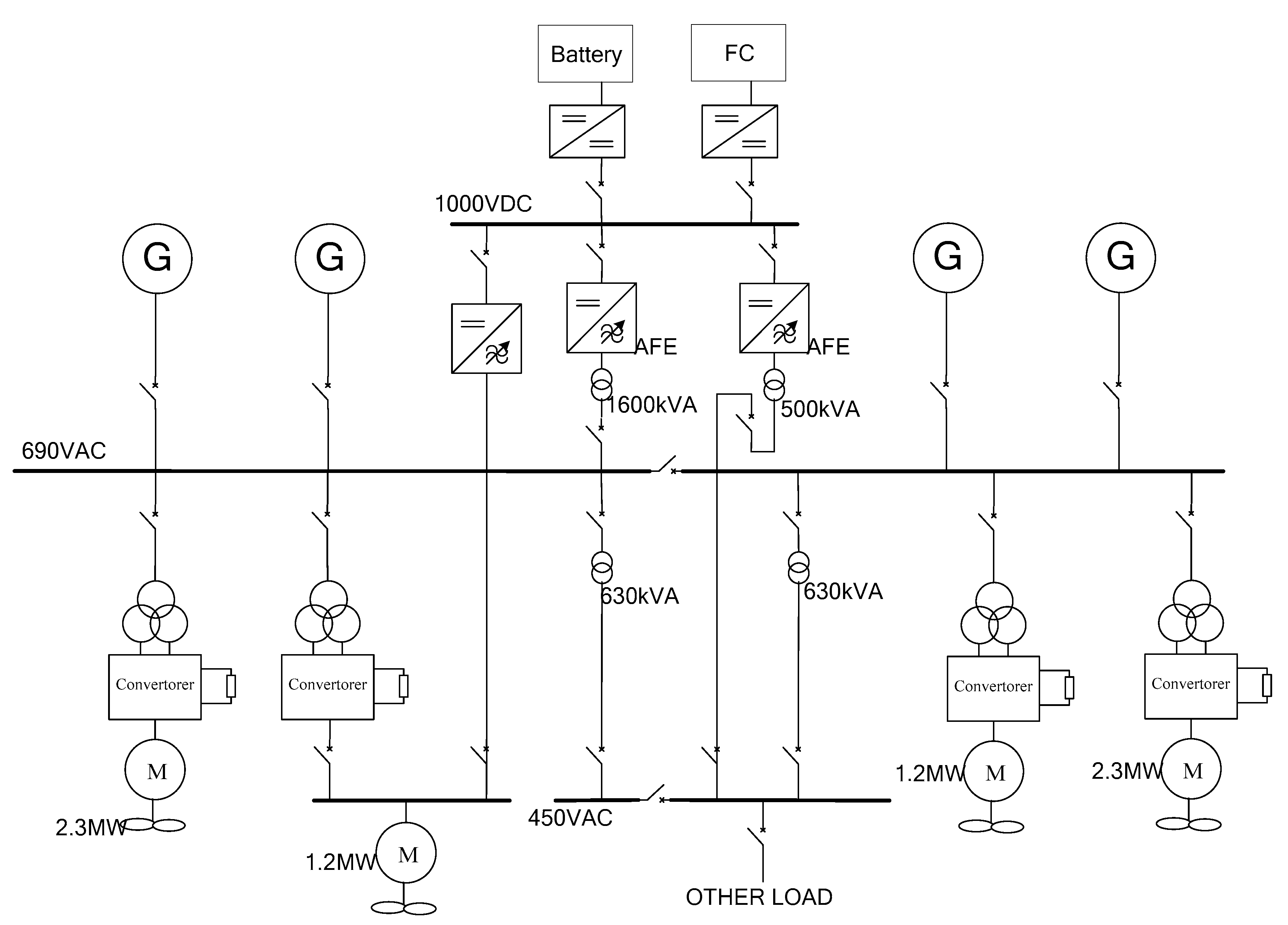
In the subsequent Viking Lady project, the ship was supplied by generators in high-power mode, while the fuel cells were only used as a power source in low-power mode. The ship used an AC electric propulsion system, as shown in Figure 2, because an electric propulsion system needs to use large capacity power electronic equipment (such as rectifiers and inverters), and this equipment will inevitably produce a large number of harmonics. Therefore, the power system needs to use multi-pulse rectifiers to suppress harmonics, while fuel cells need to use AFE (Active Front End) converters for the same purpose.
2.2. Safety Principles of International Codes and Features of the Pilot Fuel Cell Powered Ship
To ensure the safety of life at sea and prevent pollution caused by ships, the statutory survey of ships is mandatory. Ships and important products on-board must be surveyed following international codes and the requirements of the flag state government. IMO has issued IGF CODE [22] to address the safe use of low-flash fuels on ships; this code only includes specific requirements for natural gas. However, fuels such as hydrogen must be addressed by the guidelines for an alternative design. Therefore, after the 5th session of the IMO Sub-Committee on CCC (Carriage of Cargoes and Containers) in 2018, the correspondence group on the development of technical provisions for the safety of ships using Low-flashpoint Fuels of the IMO began to finalize the draft interim guidelines for the safety of ships using fuel cell power installations. Therefore, the safety, reliability, and dependability of the fuel cell power systems should be equivalent to that achieved with conventional oil-fuelled machinery installations, regardless of the specific fuel cell type and fuel.
The main safety design principles of the IMO interim guidelines can be summarized as “single failure safety” and “explosion prevention”. Unlike fuel cell vehicles, in the event of any single failure of the fuel cells, as well as risk-reducing measures and safety actions (e.g., cutting off a faulty fuel pipeline or shutting down a fuel cell), should not result in an unacceptable loss of power to the ship.
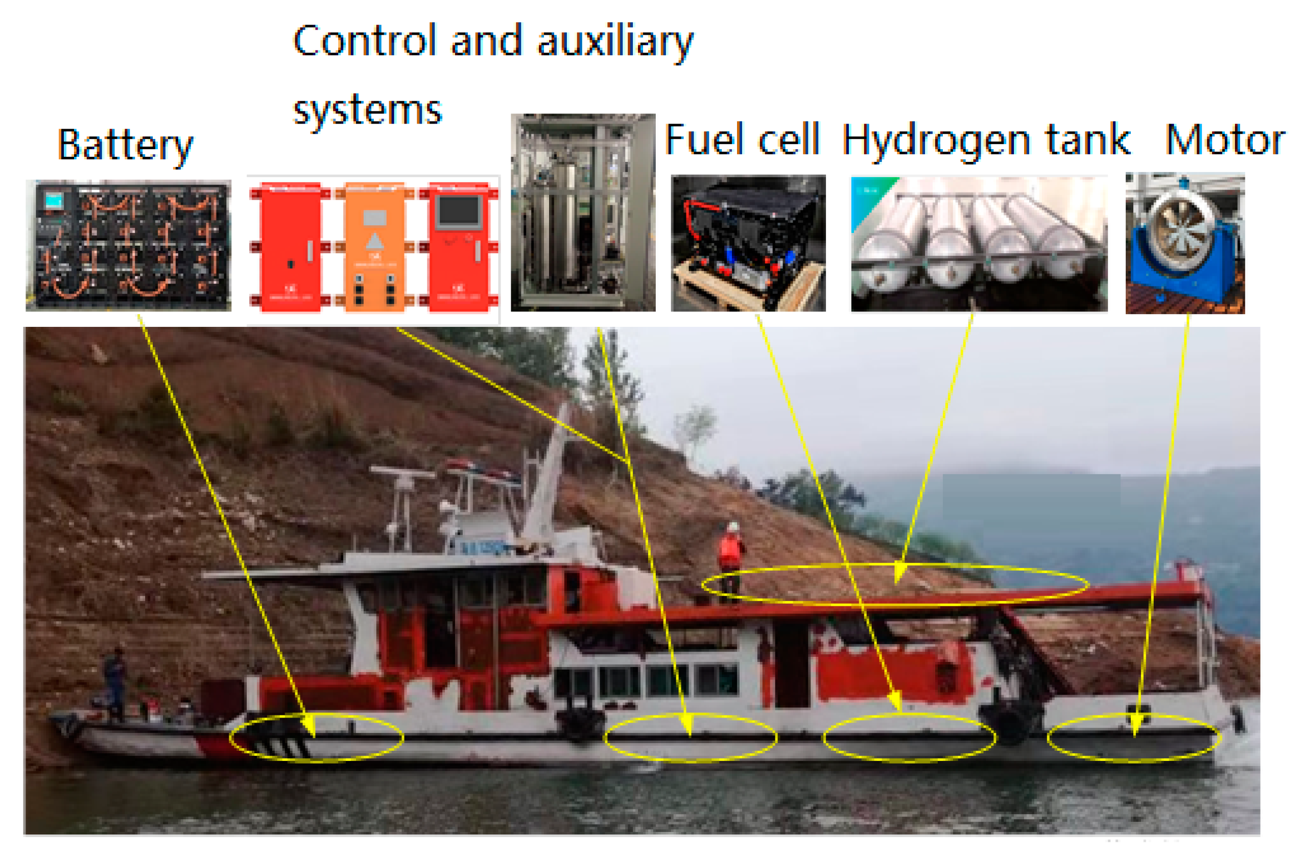
Focus on the application of low-carbon new energy in ships has ensured many fuel cell powered ships have been designed to sail in the Yangtze River and Pearl River. This paper selects one of them, a service ship in the Three Gorges area, as an example. The rated power of the ship’s fuel cell is required to reach 500 kW, fully realizing “zero emissions” of NOX, SOX, and GHG. To achieve this goal, the ship is equipped with eight sets of fuel cell modules. The fuel cell modules and their control and auxiliary systems are provided by the CSIC No. 712 Institute, the rated power of each fuel cell module is 70 kW, the output current is 0–400 A, the output voltage is 200–380 V, and efficiency is above 45%. The ship is equipped with 200 kWh lithium batteries; the batteries are made up of about 300 battery cells, each rated at 3.22 V with a capacity of 202 Ah. Power from the fuel cell modules and the lithium batteries drive two 200 kW, 400 V, and 985 rpm induction motors to propel the ship. The hydrogen source device adopts eight sets of fully-wrapped composite cylinders with aluminum alloy liner for the onboard storage of compressed hydrogen gas; the capacity of each cylinder is 320 L; the design pressure is 35 MPa; the thickness of the shell is 5.5 mm, and the hydrogen storage capacity is about 7.68 kg. Therefore, the total hydrogen storage capacity is about 60 kg. All these major equipment have been certified to be installed onboard by the China Classification Society. The general arrangement of the ship is shown in Figure 3.
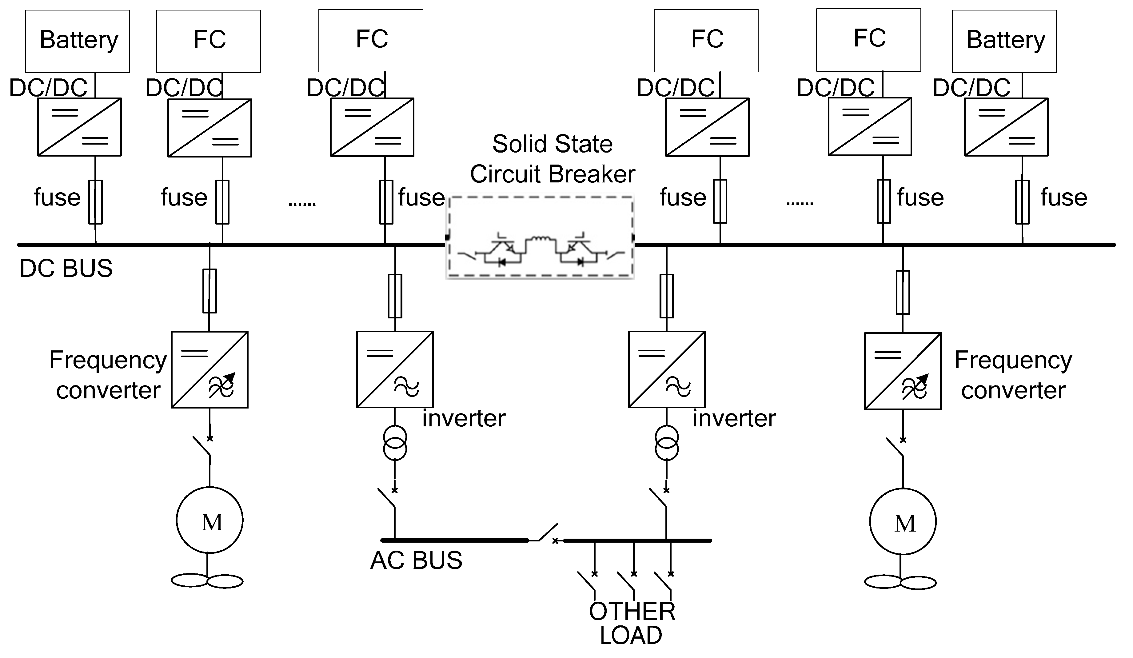
As the ship only uses fuel cells and lithium batteries as the power sources, a DC-bus power system is adopted (as shown in Figure 4). In parallel operation mode, the AC-bus power system needs to control three parameters: frequency, voltage, and phase. The DC-bus power system only needs to control one parameter: voltage, so it has faster connection speed, better stability, and no harmonic problems. Therefore, the rectifier transformer can be eliminated, power system loss can be reduced, and fuel efficiency can be improved.
To achieve the purpose of “single failure safety”, the primary safety task of the DC-bus power system is to ensure that a single point failure of the system will not cause unacceptable power loss of the whole ship. Therefore, we have made the following arrangements for the protection design:
- The lithium battery output circuit is protected by a fast fuse in the lithium battery control box.
- When any power module (inverter, converter, or DC/DC) and its incoming line is short-circuited, all capacitors of other modules feed short-circuit current to the short-circuit point and blow the fuse of the faulty branch first.
- When the DC-bus has a short circuit fault, the solid-state circuit breaker can be cut off quickly to ensure the continuity of the power supply on the non-fault side of the DC-bus, and to ensure that half of the ship’s power will not be lost.
To achieve the purpose of “explosion prevention”, it is necessary to prevent the accidental accumulation of explosive, flammable, or toxic gas concentration. Unlike a traditional internal combustion engine, a fuel cell module contains a complex cycle of gas, air, and water, as well as an electrochemical reaction zone. The fuel cell space on a ship is usually below the main deck, which is an enclosed space. If a minor leak is not handled properly, hydrogen can easily accumulate and explode.
Therefore, area classification is needed, and in the shipbuilding industry, the method of IEC 60092-502 [23] is usually adopted. Low flash fuel pipelines, valves, and connectors are considered to be release sources; therefore, the fuel cell space with these release sources inside should be considered as hazardous area zone 1, which means all electrical apparatus used in the fuel cell space are certified explosion-proof to minimize the ignition sources in the hazardous area.
Unfortunately, this method can have some negative effects on the layout and design of ships, such as:
- All electrical apparatus in the fuel cell space (including the fuel cell itself) must be certified suitable for zone 1, which is almost impossible to do;
- In accordance with IEC 60092-502, any cabin with a door or similar access to the fuel cell space should also be considered as hazardous area zone 1;
- Ventilation inlets to the fuel cell space should also be considered as hazardous area zone 1 and should be located away from other ventilation inlets and outlets, which increases the difficulty of the arrangement.
Therefore, for fuel cell powered ships, another principle we employ is to use a large amount of ventilation, so that even if there is a leak, the explosive gas environment can be confined to a small enough area and can be diluted and eliminated in a short enough time. The IEC 60079-10-1 standard deals with the classification of places where hazards associated with the presence of flammable gases or vapors may occur and can therefore be used as a basis for making the correct choice and installation of equipment for use in hazardous locations. Accordingly, we use the quantitative calculation method of IEC60079-10-1 to evaluate the risk posed by these small leaks, and the degree of hazardous areas of the fuel cell space can be classified again.
3. Research on Explosion Protection Safety of Fuel Cell Space On-Board
In this case, the fuel cells are arranged in the fuel cell space below the aft deck of the ship (length × width × height is approximately 6 m × 3 m × 2.5 m, volume V0 = 45 m3). The fuel cell space contains 8 fuel cell modules and a large number of hydrogen pipeline valves and connectors.
3.1. Fuel Cell Module Leak Estimation
It is generally believed that even during the normal operation of the fuel cell modules, a certain amount of hydrogen will leak and may accumulate in the fuel cell space.
Firstly, the leakage amount of the fuel cell modules is measured by a gas leakage test. Here, fuel leakage is measured by the test method of IEC 62282-3-100 and IEC 62282-2-100 standards [24,25].
As H2 is flammable and explosive, N2 is used as the test gas in this test. The test gas enters the hydrogen inlet, air inlet, and water inlet of the fuel cell module and is gradually pressurized to the maximum working pressure (200 kPa). At the same time, the hydrogen outlet, air outlet, and water outlet are sealed, and the pressure is kept stable for 1 min. The leakage rate of the test gas is measured by an Azbil MQV2000 gas flow meter. The gas leakage rate measured during the test is 86 mL/min (N2), and the N2 test results need to be converted.
High-density gas leaks less than low-density gas. The gas leakage rate is inversely proportional to the square root of the gas density, defining the conversion coefficient R1 as:
where, R1 is a possible ratio of H2 leakage rate to N2 leakage rate; N2SG is the relative density of N2 (atmospheric pressure, temperature 300 K), 0.963; H2SG is the relative density of H2 (atmospheric pressure, temperature 300 K), 0.0695.
High-viscosity gas leaks less than low-viscosity gas. N2 has a higher viscosity than H2, so H2 has a higher leakage rate at the same temperature and pressure. The gas leakage rate is inversely proportional to the dynamic viscosity of the gas, defining the conversion coefficient R2 as:
where, R2 is a possible ratio of H2 leakage rate to N2 leakage rate; μN2 is the gas viscosity of N2 (atmospheric pressure, temperature 300 K), 40.14 lbf × s/ft2; μH2 is the gas viscosity of H2 (atmospheric pressure, temperature 300 K), 20.95 lbf × s/ft2.
To determine which of the Formulas (1) or (2), is more suitable for a given case, additional tests are often required. To simplify the process, only the maximum leakage is usually considered, so the larger one of R1 and R2 can be used in this example.
Therefore, the leakage rate of gas H2 (LH2) can be converted from the leakage rate of test gas N2 (LN2):
According to Formulas (1)–(3), the H2 leakage rate LH2 = 320.1 mL/min, that is, (dG/dt)FC = 9.59 × 10⁻⁷ kg/s (atmospheric pressure).
According to the area classification standard of the release source, this leakage source is expected to release H2 under normal conditions, so it belongs to the primary grade of release source.
3.2. Leak Estimation of Other Release Sources in Fuel Cell Space
To determine the risk level of the fuel cell space, it is also necessary to estimate the maximum release rate of various gas release sources through quantitative calculation. Apart from the fuel cell module, the other main release sources are connectors, such as threaded joints, or 24-degree cone connectors, on the H2 pipeline. These release sources do not normally release H2, but accidental and short-term releases are possible. Therefore, they belong to the secondary grade of release source. The release rate of such sources is influenced by the internal gas pressure, molecular mass, the geometry of the release source, and the concentration of flammable gases in the release mixture.
H2 pipeline connections in the fuel cell space are all threaded joints, and the diameter of hydrogen pipelines is less than 50 mm. Therefore, the number, type, and suggested hole cross-section of the release sources in the H2 pipelines for the eight sets of fuel cell modules are shown in Table 2.
Usually, when damaged holes occur on the threaded joints, the length of the hole is much shorter than the width of the hole. Therefore, when calculating the release rate of H2 leakage from the holes, the influence of gas viscosity can be ignored, while the influence of gas pressure is greater. For H2, its critical pressure Pc can be calculated as follows:
where, P0 is the external atmospheric pressure, 105 Pa; M is the molecular weight of the H2, 2 kg/kmol; R is the universal gas constant; Cp is the specific heat at a constant pressure of H2, J/(kg × K). Consequently, pc = 1.90 × 10⁵ Pa.
In this case, the internal pressure of the H2 supply pipeline is 600 kPa, higher than that of pC, so the gas is choked. The velocity of choked gas is equal to the speed of sound, which is the maximum theoretical discharge velocity. Therefore, the release rate of leakage through the damaged hole can be estimated by the following formula:
where, S is the hole cross-section; P is the internal pressure of the H2 supply pipeline, 6 × 10⁵ Pa.
According to Formulas (4)–(6), the leakage rate of 64 threaded joints is (dG/dt)c1-c64 = 9.2 × 10⁻⁶ kg/s due to the same pressure and suggested hole cross-section of 64 threaded joints.
3.3. Hazardous Area Classification of Fuel Cell Space
As the fuel cell space is located below the ship’s main deck, only mechanical ventilation can be used. In this case, ventilation is undertaken 50 times per hour to dilute the gas concentration, thus reducing the likelihood of an explosion. To limit the gas concentration below 25%LEL, the minimum airflow rate can be calculated as:
where, LELV is the lower explosive limit of H2, 4 (%). Substitute the release rate of each release source into Formula (7), then the required airflow rate of each fuel cell module is (dV/dt)FC = 0.0012 m3/s, and the required airflow rate of each threaded joint in the H2 supply pipeline is (dV/dt)c1-c64 = 0.011 m3/s. According to the probability coefficient of simultaneous release of the release sources given in Table B.3 of IEC60079-10-1, there are 8 primary grade of release sources (fuel cell modules) and 64 secondary grade of release sources in this example. Therefore, the total required airflow rate can be calculated by the following formula.
Therefore, the total airflow required for the fuel cell space is (dV/dt)sum = 0.0158 m3/s.
Considering the obstruction of airflow caused by the supporting structure in the fuel cell space, the ventilation efficiency coefficient f is set as 1.5, and Vz is defined as the volume of an explosive gas environment caused by the H2 release from the release sources. Therefore, Vz can be calculated by the following formula:
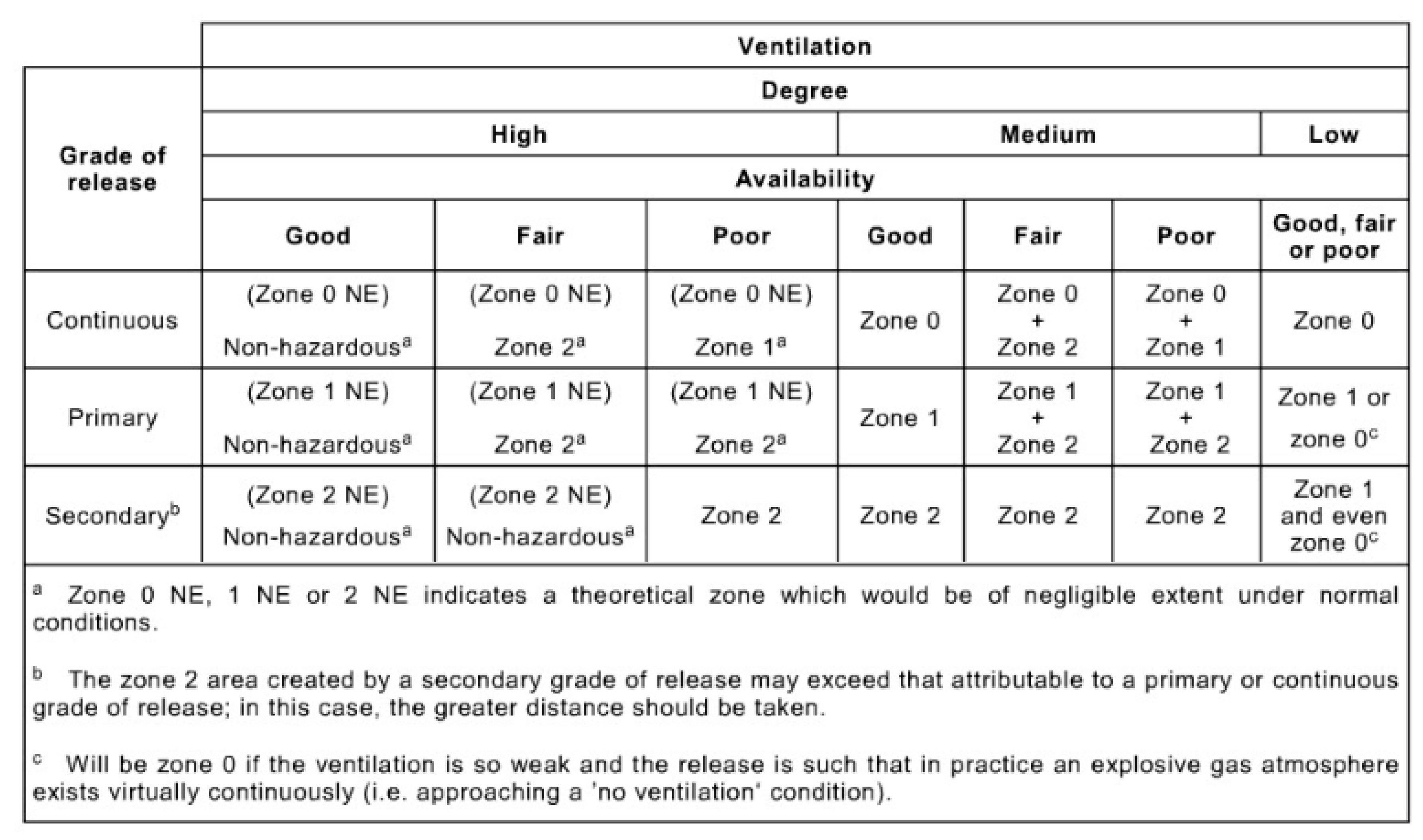
where, C is the frequency of air changes provided by mechanical ventilation, s−1. Therefore, VZ = 1.71 m3 > 0.01 V0 = 0.45 m3. This means that the current ventilation is not sufficient to reduce the volume of the explosive gas environment caused by the release of H2 from the release sources and can only be considered as medium dilution effectiveness ventilation. According to table B.1 of IEC60079-10-1 (Figure 5), if there is only medium dilution effectiveness ventilation, the fuel cell space should be regarded as hazardous zone 2. However, the negative impact of the presence of hazardous areas on ship design cannot be completely solved.
3.4. Measures to Reduce the Hazard Level of the Fuel Cell Space
Then the following changes were made in the ship’s design:
- The fuel cell modules are designed to be gas-tight, with internal ventilation and vents placed outside the fuel cell space.
- Increase the ventilation fan power.
- Install two sets of fans, and the power supply is independent of the main switchboard and emergency switchboard. When any fan fails, 100% ventilation capacity can be maintained to ensure adequate ventilation performance.
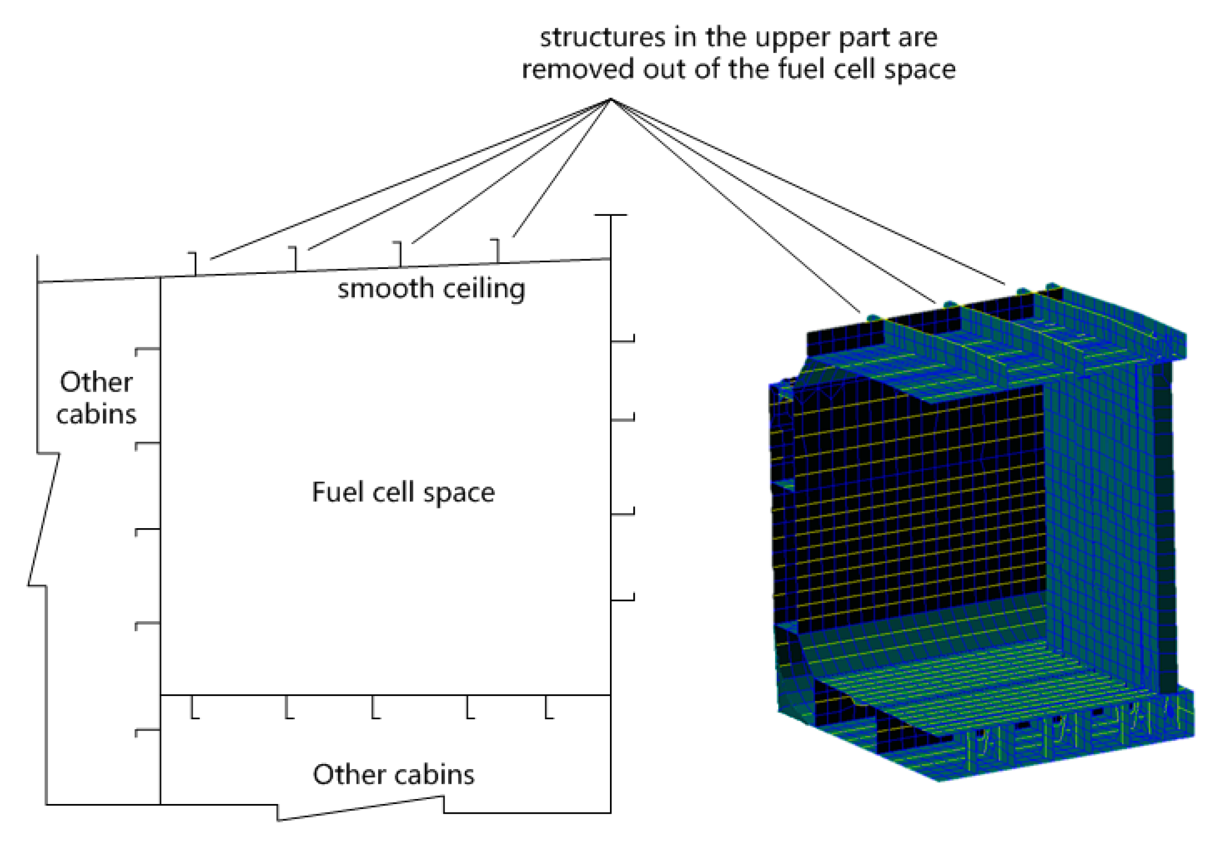
- Fuel cell spaces are designed to have an as simple geometrical shape as possible, with no obstructing structures in the upper part, and can be arranged with a smooth ceiling sloping up towards the ventilation outlet. Supporting structures such as girders and stiffeners were facing outwards (as shown in Figure 6.).
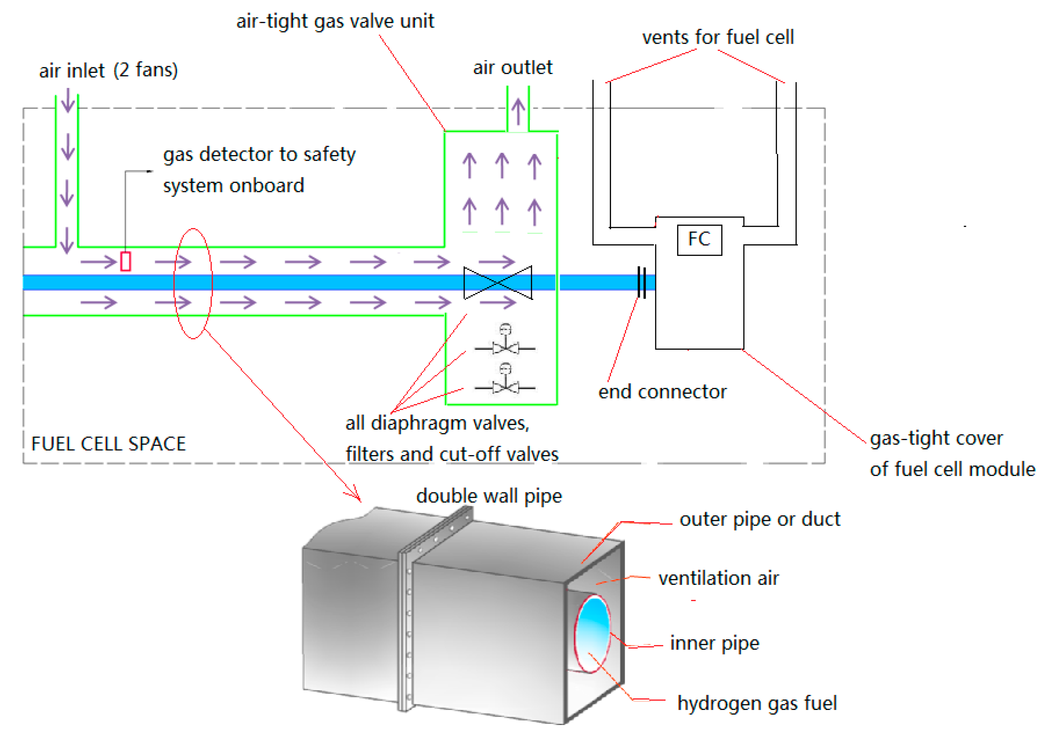
- We design a double-wall piping system to supply H2 fuel. All valves and connectors (except end connectors of fuel cell module) on the H2 supply line were arranged in a gas-tight valve box, as shown in Figure 7.
4. Results
IEC62282-2 states that when a fuel cell is placed in a gas-tight container, the gas leakage test is not required. Therefore, with the gas-tight cover, H2 released in the fuel cell module will be quickly discharged through the internal ventilation and will not leak into the fuel cell space. Therefore, the airflow required for each fuel cell module (in fuel cell space) can be considered as (dV/dt)FC = 0 m3/s.
We modify the selection of ventilation fans and selected 2 sets of 4200 m3/h ventilation fans with an independent power supply for the fuel cell space to provide about 90 h−1 of air exchange for the fuel cell space. Considering that these measures ensure the continued existence of ventilation, it can be regarded as a “good” ventilation type in Figure 5.
The airflow blockage caused by the inappropriate supporting structure arrangement in the fuel cell space is avoided. Therefore, the ventilation efficiency is improved by the modification of the structural components of the fuel cell space, so the ventilation efficiency coefficient f can be set as 1.
Due to the use of a double-wall piping system, if the first containment (blue pipe) fails, the second containment (green duct) still ensures the released H2 does not leak into the fuel cell space (Figure 7). Consequently, we just need to deal with the released H2 from the end connector of the fuel cell modules, further reducing the total probability released H2 in the fuel cell space.
Therefore, the revised Vz can be recalculated by Formula (9): Vz = 0.44 m3 < 0.01 V0. At this moment, the existing ventilation can be considered as high dilution and effective. According to Figure 5, the fuel cell space can be regarded as a non-hazardous area.
5. Discussion
The likelihood of the presence of an explosive gas atmosphere mainly depends on the release source and the rate of dispersion of the released substance through artificial ventilation. In this case, according to the general principle of risk mitigation, with an increase in airflow, continuity of ventilation, smoother ceiling sloping up towards ventilation outlet, and fewer release sources, the scope of the explosive gas environment resulting from the same amount of leakage will usually be reduced.
Using these measures, we recalculate that Vz is much less than V0 (Vz < 0.01 V0) to ensure that all measures are taken to completely reduce the risk of hydrogen accumulation in the fuel cell space. This means that in the case of H2 release, it only takes a very short time to reduce the scope of the explosive gas environment to a small enough range. This will reduce the likelihood of an explosion to an acceptable level of safety.
6. Conclusions
To achieve the IMO’s target of a 70% reduction in carbon intensity by 2050 and China’s target of carbon-neutrality by 2060, a technological path based on carbon-neutral, or zero-carbon fuels is needed. Fuel cell powered ships have huge advantages in reducing emissions, but these ships lack the safety experience of traditional, internal combustion-engine ships. The purpose of this paper is to explore ways to solve the risk of H2 leakage in the fuel cell space, select a variety of typical release sources for analysis, and optimize the fuel cell space layout, ventilation, and fuel cell module design. The quantitative calculation result shows that the optimized design method can greatly limit the scope of explosive gas environment caused by the H2 leakage of the release sources and counteract the negative influence of dangerous area on ship design. Therefore, the measures to reduce the level of risk applied to the pilot project are appropriate in the work. However, future research will include further discussion on extending these measures to the case of passenger ships and on a critical analysis of the inherent uncertainties in the risk assessments, including estimation of event frequencies (leak, ignition, etc.) for these emerging technologies.
Author Contributions
L.C. and W.G. designed the model and the computational framework and analyzed the data. W.G. carried out the implementation. L.C. performed the calculations. L.C. and W.G. wrote the manuscript with input from all authors. L.C. conceived the study and was in charge of overall direction and planning. All authors have read and agreed to the published version of the manuscript.
Funding
This research was funded by the ‘Key Technology Research on Hydrogen Fuel Powered Ships’ of High-tech Ship Research Project from the Ministry of Industry and Information Technology of the People’s Republic of China (project ID MC-202023-C11).
Institutional Review Board Statement
Not applicable. This study do not involve humans or animals.
Informed Consent Statement
Not applicable. This study do not involve humans.
Data Availability Statement
The data used to support the findings of this study are available from the corresponding author upon request.
Acknowledgments
We sincerely thank CSIC No. 712 Institute and Wuhan Troow in Power System Technology Co, Ltd. for their assistance in the testing of the fuel cell modules leakage process.
Conflicts of Interest
The authors declared that they have no conflicts of interest in this work. The authors declare that we do not have any commercial or associative interest that represents a conflict of interest in connection with the work submitted.
References
- A hydrogen Strategy for a Climate-Neutral Europe. Available online: https://ec.europa.eu/energy/sites/ener/files/hydrogen_strategy.pdf (accessed on 7 August 2020).
- Roadmap to Zero Emission from International Shipping 2020. Available online: https://www.mlit.go.jp/en/maritime/GHG_roadmap_en.html (accessed on 27 May 2020).
- Die Nationale Wasserstoffstrategie. Available online: https://www.bmwi.de/Redaktion/DE/Publikationen/Energie/die-nationale-wasserstoffstrategie.html (accessed on 6 October 2020).
- Speers, P. Hydrogen Mobility Europe (H2ME): Vehicle and Hydrogen Refuelling Station Deployment Results. World Electr. Veh. J. 2018, 9, 2. [Google Scholar] [CrossRef] [Green Version]
- Sokolsky, S.; Tomić, J.; Gallo, J.-B. Best Practices in Hydrogen Fueling and Maintenance Facilities for Transit Agencies. World Electr. Veh. J. 2016, 8, 553–556. [Google Scholar] [CrossRef] [Green Version]
- Wu, D.; Ren, J.; Davies, H.; Shang, J.; Haas, O. Intelligent Hydrogen Fuel Cell Range Extender for Battery Electric Vehicles. World Electr. Veh. J. 2019, 10, 29. [Google Scholar] [CrossRef] [Green Version]
- Yamada, E.; Mashiba, T. Development of Technical Regulations for Fuel Cell Motorcycles in Japan—Hydrogen Safety. World Electr. Veh. J. 2019, 10, 48. [Google Scholar] [CrossRef] [Green Version]
- Li, Y.; Bi, M.; Zhou, Y.; Jiang, H.; Huang, L.; Zhang, K.; Gao, W. Experimental and theoretical evaluation of hydrogen cloud explosion with built-in obstacles. Int. J. Hydrog. Energy 2020, 45, 28007–28018. [Google Scholar] [CrossRef]
- Cao, W.; Li, W.; Yu, S.; Zhang, Y.; Shu, C.-M.; Liu, Y.; Luo, J.; Bu, L.; Tan, Y. Explosion venting hazards of temperature effects and pressure characteristics for premixed hydrogen-air mixtures in a spherical container. Fuel 2021, 290, 120034. [Google Scholar] [CrossRef]
- Skob, Y.; Ugryumov, M.; Granovskiy, E. Numerical assessment of hydrogen explosion consequences in a mine tunnel. Int. J. Hydrog. Energy 2020, 46, 12361–12371. [Google Scholar] [CrossRef]
- Qin, Y.; Chen, X. Flame propagation of premixed hydrogen-air explosion in a closed duct with obstacles. Int. J. Hydrog. Energy 2021, 46, 2684–2701. [Google Scholar] [CrossRef]
- Shi, J.; Chang, B.; Khan, F.; Chang, Y.; Zhu, Y.; Chen, G.; Zhang, C. Stochastic explosion risk analysis of hydrogen production facilities. Int. J. Hydrog. Energy 2020, 45, 13535–13550. [Google Scholar] [CrossRef]
- Ustolin, F.; Paltrinieri, N.; Berto, F. Loss of integrity of hydrogen technologies: A critical review. Int. J. Hydrog. Energy 2020, 45, 23809–23840. [Google Scholar] [CrossRef]
- De-Troya, J.J.; Álvarez, C.; Fernández-Garrido, C.; Carral, L. Analysing the possibilities of using fuel cells in ships. Int. J. Hydrog. Energy 2016, 41, 2853–2866. [Google Scholar] [CrossRef]
- Ghenai, C.; Bettayeb, M.; Brdjanin, B.; Hamid, A.K. Hybrid solar PV/PEM fuel Cell/Diesel Generator power system for cruise ship: A case study in Stockholm, Sweden. Case Stud. Therm. Eng. 2019, 14, 100497. [Google Scholar] [CrossRef]
- Safety Considerations and Approval Procedures for the Integration of Fuel Cell on Board of Ships. Available online: http://conference.ing.unipi.it/ichs2009/images/stories/papers/7.pdf (accessed on 2 December 2016).
- IEC 60079-10-1:2008, Explosive Atmospheres—Part 10-1: Classification of Areas—Explosive Gas Atmospheres. Available online: https://webstore.iec.ch/publication/622 (accessed on 9 December 2008).
- Baldi, F.; Moret, S.; Tammi, K.; Maréchal, F. The role of solid oxide fuel cells in future ship energy systems. Energy 2020, 194, 116811. [Google Scholar] [CrossRef]
- Abe, J.O.; Popoola, A.P.I.; Ajenifuja, E.; Popoola, O.M. Hydrogen energy, economy and storage: Review and recommendation. Int. J. Hydrog. Energy 2019, 44, 15072–15086. [Google Scholar] [CrossRef]
- EMSA Study on the Use of Fuel Cells in Shipping. Available online: http://www.emsa.europa.eu/newsroom/latest-news/item/2921-emsa-study-on-the-use-of-fuel-cells-in-shipping.html (accessed on 23 January 2017).
- Hou, Y. Simulation of Fuel Cell Power Generation System and Parallel Control Research. Master’s Thesis, Wuhan University of Technology, Wuhan, China, 2012. [Google Scholar]
- International Code of Safety for Ship Using Gases or Other Low-flashpoint Fuels (IGF Code). Available online: https://wwwcdn.imo.org/localresources/en/KnowledgeCentre/IndexofIMOResolutions/MSCResolutions/MSC.391(95).pdf (accessed on 11 June 2015).
- IEC 60092-502:1999, Electrical Installations in Ships—Part 502: Tankers—Special Features. Available online: https://webstore.iec.ch/publication/704#additionalinfo (accessed on 10 February 1999).
- IEC 62282-3-100:2019, Fuel Cell Technologies—Part 3-100: Stationary Fuel Cell Power Systems—Safety. Available online: https://webstore.iec.ch/publication/59566 (accessed on 12 February 2019).
- IEC 62282-2-100:2020, Fuel Cell Technologies—Part 2-100: Fuel Cell Modules—Safety. Available online: https://webstore.iec.ch/publication/59780 (accessed on 7 May 2020).
Figure 1.
Fuel cells and batteries hybrid system on ZemShip.

Figure 2.
Fuel cells and batteries and generators hybrid system on Viking Lady.

Figure 3.
Fuel cell powered ship of the pilot project in China.

Figure 4.
Single line drawing of the pilot project in China.

Figure 5.
Zones for the grade of release and effectiveness of ventilation.

Figure 6.
Schematic design of fuel cell space.

Figure 7.
Schematic design of a double-wall piping system, air-tight gas valve unit, and gas-tight cover of the fuel cell.
Figure 7.
Schematic design of a double-wall piping system, air-tight gas valve unit, and gas-tight cover of the fuel cell.


Table 1.
Basic information of some fuel cell powered ships.
| Project | Function | Type of FC | Type of Fuel |
|---|---|---|---|
| FellowSHIP | Propulsion & Electric generation | 320 kW MCFC | LNG |
| Viking Lady | Propulsion & Electric generation | 20 kW SOFC | Methanol |
| E4Ships-PA-X-ell | Electric generation | 2 × 30 kW HT-PEM | Methanol |
| E4Ships-SchIBz | Electric generation | 100 kW SOFC | Diesel |
| ZemShip | Propulsion | 96 kW PEM | Hydrogen |
| Nemo H2 | Propulsion | 60 kW PEM | Hydrogen |
| US SSFC | Electric generation | 625 kW MCFC | Diesel |
Table 2.
Release sources statistics of fuel cell space.
| Valves and Connectors | Type of Connection | Number of Release Sources | Suggested Hole Cross-Section |
|---|---|---|---|
| diaphragm valve | threaded joints | 16 | 0.025 mm2 |
| filter | threaded joints | 16 | 0.025 mm2 |
| cut-off valve | threaded joints | 24 | 0.025 mm2 |
| end connector to FC | threaded joints | 8 | 0.025 mm2 |
Publisher’s Note: MDPI stays neutral with regard to jurisdictional claims in published maps and institutional affiliations. |
© 2021 by the authors. Licensee MDPI, Basel, Switzerland. This article is an open access article distributed under the terms and conditions of the Creative Commons Attribution (CC BY) license (https://creativecommons.org/licenses/by/4.0/).
Share and Cite
MDPI and ACS Style
Chen, L.; Guan, W. Safety Design and Engineering Solution of Fuel Cell Powered Ship in Inland Waterway of China. World Electr. Veh. J. 2021, 12, 202. https://0-doi-org.brum.beds.ac.uk/10.3390/wevj12040202
AMA Style
Chen L, Guan W. Safety Design and Engineering Solution of Fuel Cell Powered Ship in Inland Waterway of China. World Electric Vehicle Journal. 2021; 12(4):202. https://0-doi-org.brum.beds.ac.uk/10.3390/wevj12040202
Chicago/Turabian StyleChen, Lijian, and Wenfeng Guan. 2021. "Safety Design and Engineering Solution of Fuel Cell Powered Ship in Inland Waterway of China" World Electric Vehicle Journal 12, no. 4: 202. https://0-doi-org.brum.beds.ac.uk/10.3390/wevj12040202