1. Introduction
Distributed electric propulsion aircraft (DEPA) is a new type of aircraft, whose multiple propellers or fans distributed on the wings or fuselage that provide the aircraft with the main thrust are driven by motors. It is expected to further improve the energy conversion efficiency of the aircraft power system and reduce fuel consumption [
1,
2]. The electrical system of the aircraft includes a propulsion system and an aircraft power supply (APS) system. The load is supplied by the generator, to achieve the purpose of a comprehensive utilization of energy and unified management. However, due to the large increase in electrical equipment and the continuous improvement of the power level of the power supply system, the generator capacity must meet the power demand of the load, which brings new challenges to the design of aero engines. In addition, due to the increasingly complex operating conditions during aircraft operations, high-power loads represented by electric motors will cause severe transient power shocks to the APS at the moments of starting, sudden loading, and sudden unloading. It will cause severe fluctuations in the bus voltage and make the generator set deviate from its optimal working condition, which affects the stability of the system [
3,
4].
For above problems, the most effective method is to match the load power fluctuations through the charging and discharging characteristics of the HESS. Among many energy storage devices (ESD), batteries have the characteristics of high-energy density and low self-discharge rate. Supercapacitors have the advantages of a long-life cycle and high-power-density, which can provide greater power quickly and provide buffering for others. The advantages of the two complement each other, which can provide high-power and high-energy-density electric energy safely, compactly, and lightly. It plays an important role in responding to changes in the load power to maintain bus voltage stability and reduce generator capacity requirements [
5,
6].
Therefore, an energy management strategy (EMS) for HESS becomes particularly important, which mainly focuses on power distribution to improve the bus voltage stability and optimize the size and life of HESS. At present, the control strategy to suppress the fluctuation of the load power is generally based on the filtering algorithm. Compared with dynamic programming, model predictive control, and fuzzy logic, it is simple and easy to implement and has better real-time performance, making it more popular [
7]. Previous literature [
8] has designed a command-filtered back-stepping controller to achieve the stability of the DC bus voltage under any load and the active power output by each power unit. Extant literature [
9] has also proposed a V-I droop control and high/low pass filters, which are used inside the primary controller top roper power sharing in different time scales. These strategies reduce the capacity of DG units. However, the impact of ESD SOC on power levelling has not been considered. Other literature [
10] has proposed a two-stage low pass filter control strategy with variable filter time constant, using the improved particle swarm optimisation with the compensating coefficient of inertia weight factor to solve the optimal output power and avoid the over limit phenomenon of the battery state of charge. However, it does not consider the power limit of the ESD. The above-mentioned LPF-based EMS are not comprehensive, and further optimization is still needed to adapt to the limited space and high reliability of aircraft electrical systems.
This paper takes the HESS of DEPA as its research object. To solve the problem of severe DC bus voltage fluctuations caused by frequent load changes and to further optimize the size and life of the HESS, this paper proposes an EMS which combines the three-step power distribution (TSPD) with the DC bus voltage outer loop and the three-current inner loop current sharing control, based on the low-pass filtering method, to realize the reasonable distribution of battery and super capacitor power. In addition, through the introduction of super capacitor SOC automatic recovery control and maximum power value dynamic limit strategy, the super capacitor SOC is maintained in an ideal state, the size of the HESS is optimized, and the service life of the ESD is prolonged. Load current feed-forward compensation control enables the DC bus voltage to quickly recover and stabilize during sudden load loading and sudden load unloading, which reduces the capacity demand of the APS.
2. Structure of HESS for DEPA
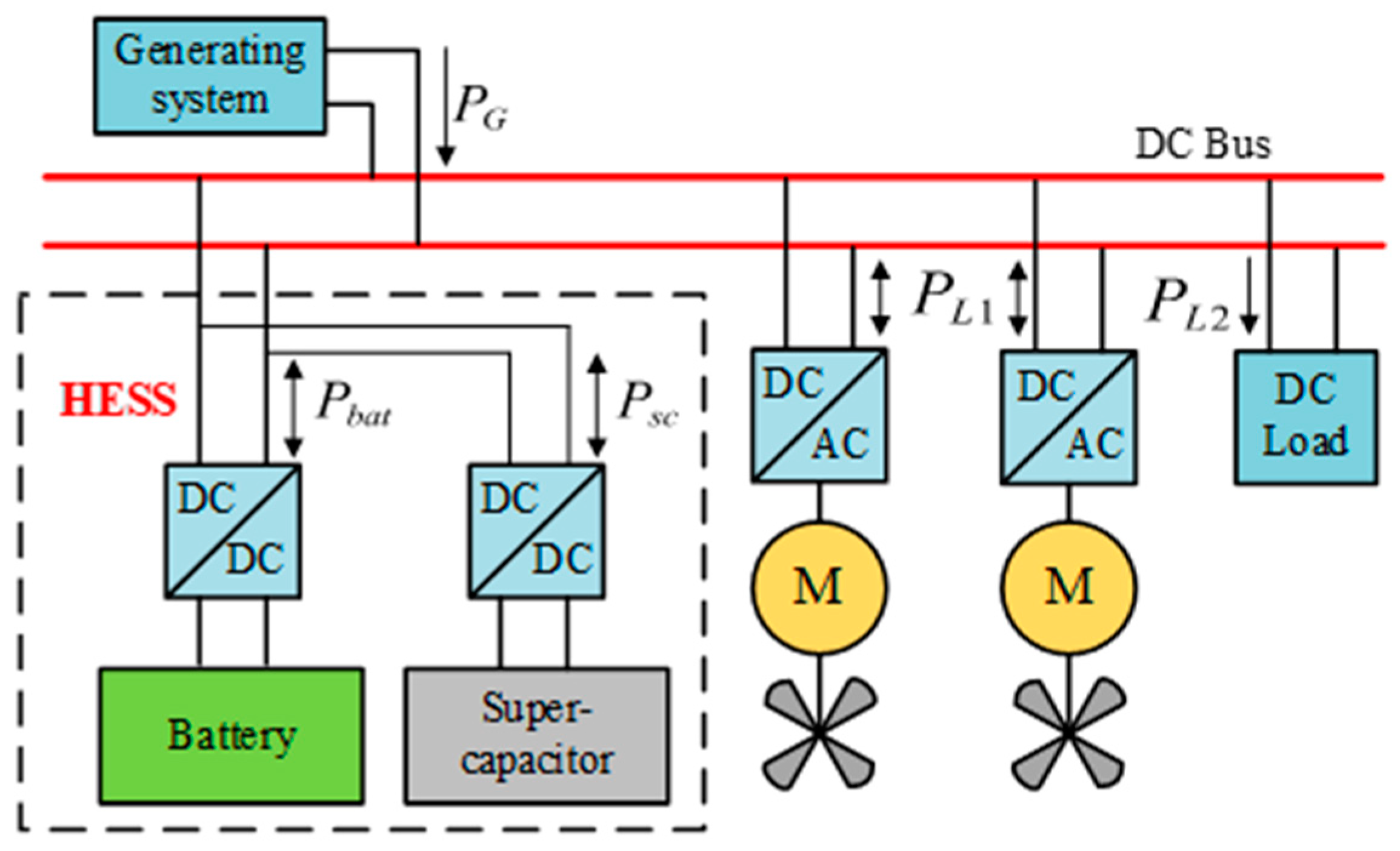
The basic structure of HESS for DEPA studied in this paper is shown in
Figure 1, where
represents power, and its direction represents the flow direction of power. To ensure the two-way flow of energy and facilitate energy management, both the battery and the super capacitor are connected to the DC bus through a DC-DC converter. The distributed hybrid electric propulsion aircraft power generation system is usually a generator driven by a gas turbine, which is the main energy source for the normal operation. Aircraft loads are mainly divided into DC loads and AC loads. Among them, the large-scale application of speed-regulating motors, servo motors, and high-speed motors has seriously affected the stability of the APS.
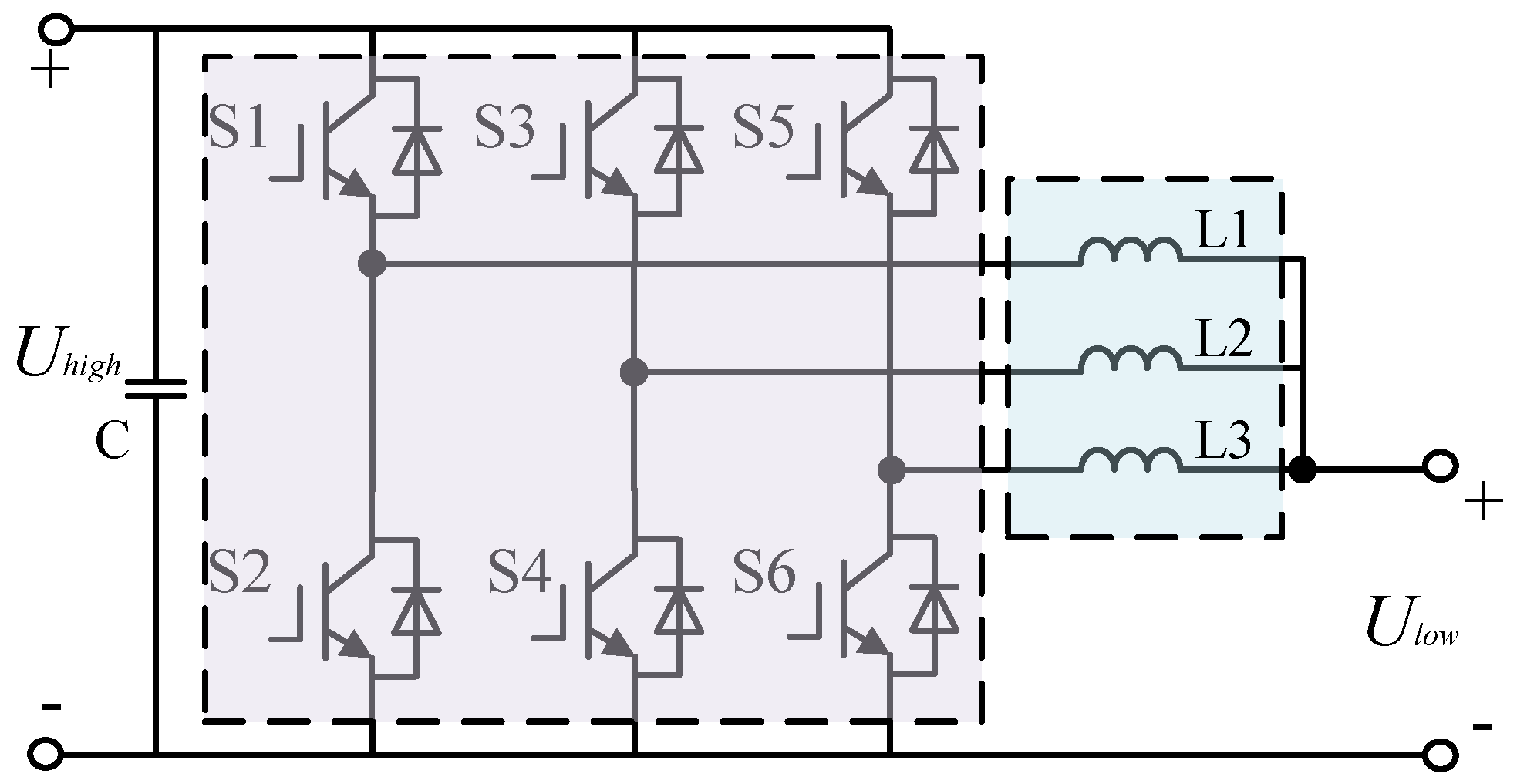
This article adopts a three-phase interleaved parallel DC-DC converter, where each phase switch tube is a complementary conduction control mode, and the drive signals of each phase differ by 120 degrees from each other. It can make the ripples of the inductor current of each phase interleaved and superimposed, thereby reducing the ripple, while reducing the switching loss [
11]. The topological structure is shown in
Figure 2.
3. Energy Management Strategy of HESS
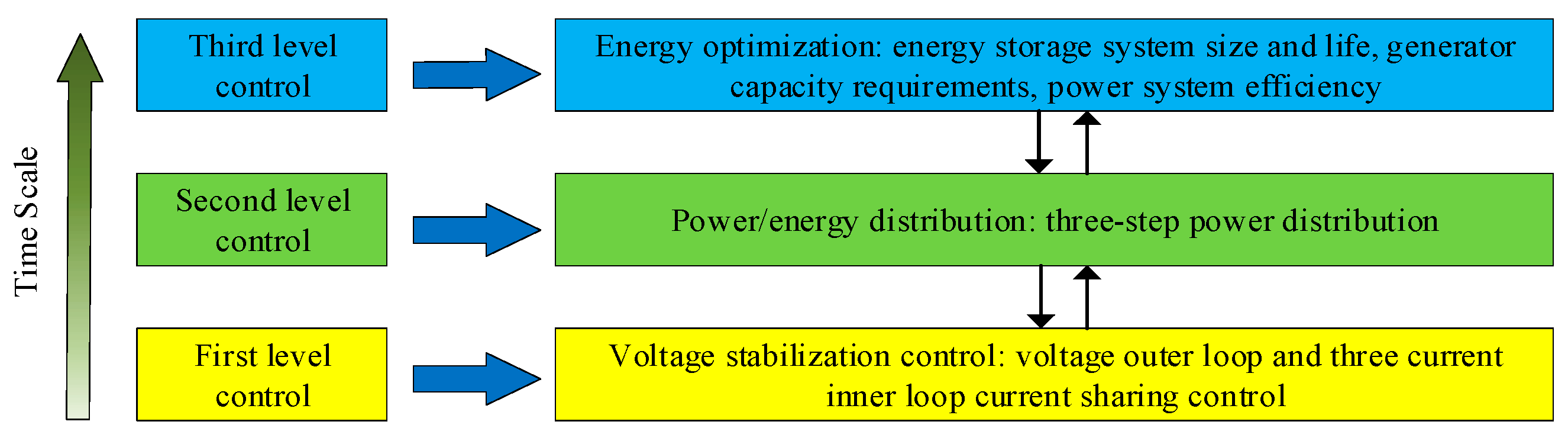
Unlike land-based micro-grids and electric vehicles, HESS on DEPA needs to be properly designed to meet the space constraints of the aircraft and the power requirements of the load. The proposed EMS needs to be based on a system composed of batteries and supercapacitors according to system functional requirements and load characteristics, which realizes the comprehensive deployment of electric energy through the charge and discharge control of ESD, the regulation control of bus voltage, and the dynamic management of load energy, thereby improving the overall efficiency and performance of the APS, optimizing the size and life of HESS, and reducing the power demand of the generator. The overall control goal of energy management is shown in
Figure 3.
3.1. Traditional Low-Pass Filter
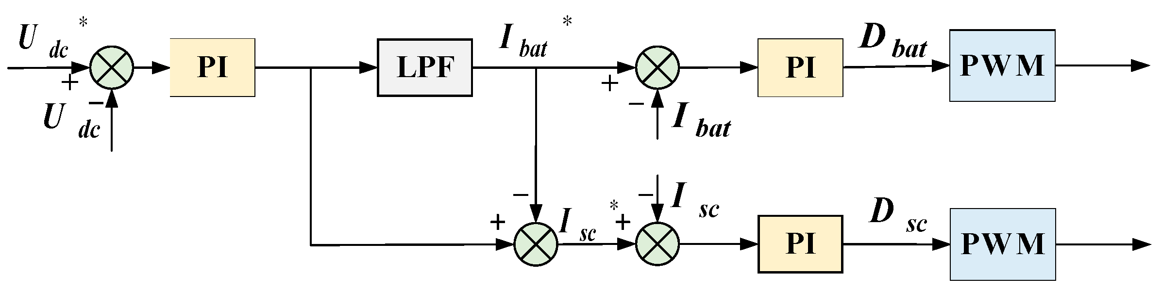
The most important thing when the HESS is working is the power distribution between different internal energy storage devices. How to coordinate the charge and discharge between them is crucial to the stability of the entire system. The traditional HESS low-pass filter power allocation strategy based on PI control is shown in
Figure 4 [
12].
The basic idea in the figure is the decoupling control of low-frequency and high-frequency voltage components, that is, how the lithium battery responds to the slow-changing voltage component, and how the super capacitor responds to the fast-changing voltage component. Since the power reference value depends on the DC bus voltage loop, its hysteresis leads to poor bus voltage dynamic recovery performance, and there are also problems such as the unreasonable state of charge of the energy storage equipment. As such, this article improves it.
3.2. Three-Step Power Distribution
3.2.1. Working Status Division of ESD
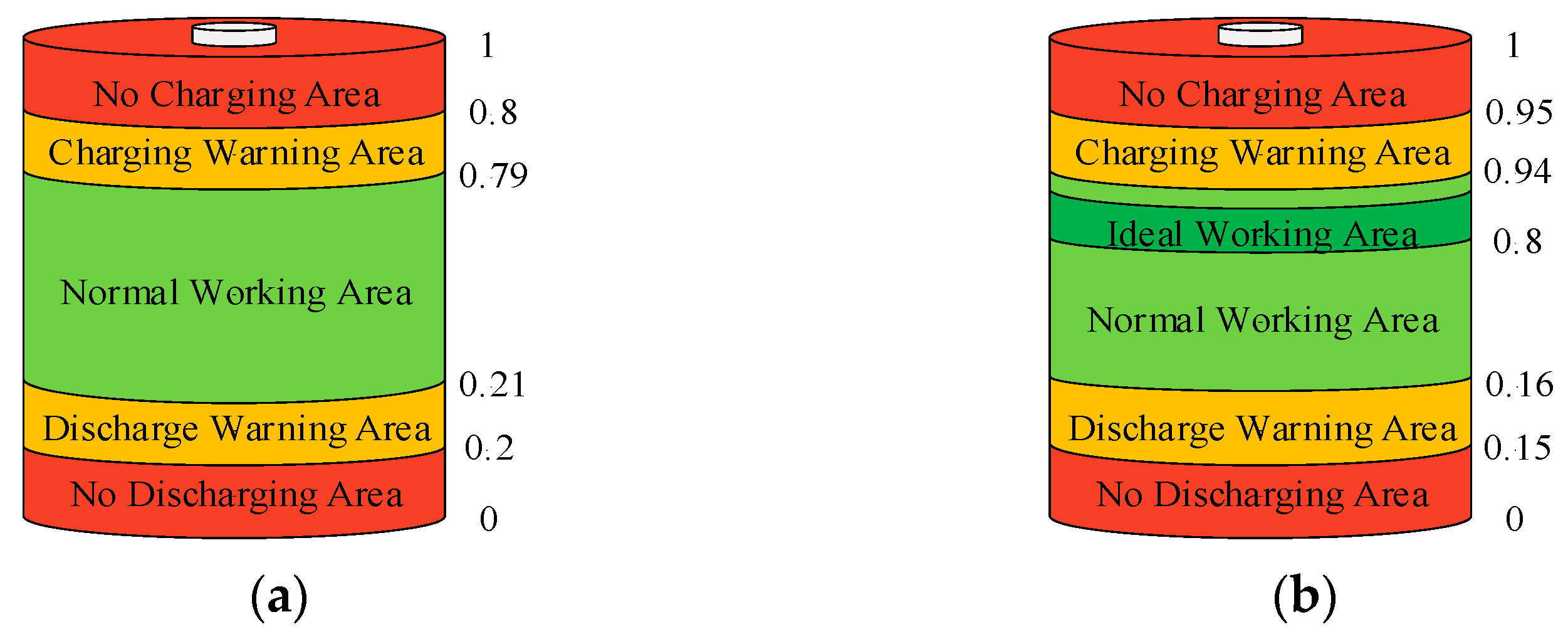
To formulate a reasonable EMS, the working range of ESD is divided as shown in
Figure 5. Each ESD is divided into five areas. In SC, an ideal working area is added, which belongs to the normal working area [
13]. During the operation of HESS, it is desirable that the supercapacitor is in or tends to the working area to deal with the next power shock. The numbers in the
Figure 5 indicate the SOC limits of each zone.
3.2.2. Low Pass Filter
The low pass filter method is widely used in the high and low frequency power decoupling of HESS due to its simple structure and strong practicability. The first-order low-pass filter circuit and bode diagram of battery output power is shown in
Figure 6.
Suppose the input voltage of the filter is
, and the output voltage is
, as can be seen from the circuit diagram, the circuit differential equation is:
where
, is called the filter time constant. Take the Laplace transform of the above formula, the s-domain transfer function can be obtained as
where
is the Laplacian operator. Therefore, it can be seen from
Figure 6b that the larger the value of
, the smaller the cut off frequency, and that the lower the output signal frequency after filtering, the more stable it is. It is suitable for filtering out low-frequency components, as the reference distribution of the battery power. Therefore, the real-time power distribution of the HESS can be realized through LPF.
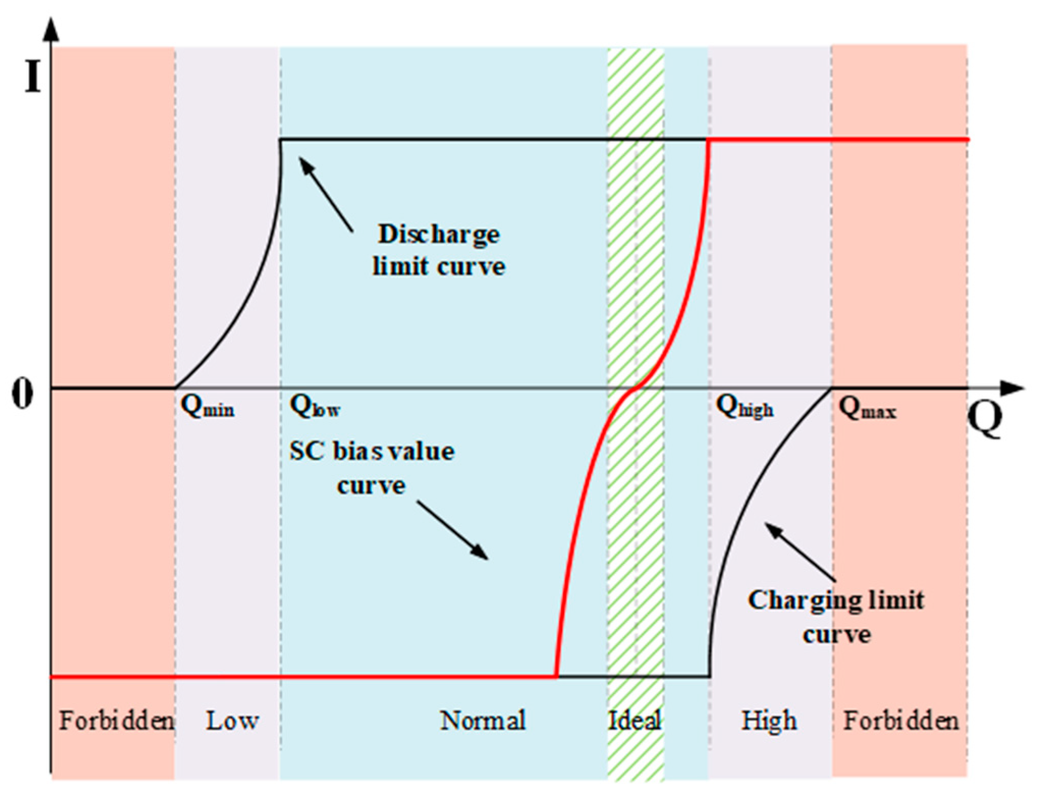
3.2.3. Super Capacitor SOC Automatic Recovery Strategy
In HESS, the main function of super capacitors is to provide or absorb high frequency power caused by load changes. However, the energy density of super capacitors is low. If they respond to high frequency power for a long time, the SOC of the super capacitor may be in a low power state. To ensure that they can respond to high-frequency power requirements during the operation of the entire system, the size must be increased to meet this unique requirement. So, it is necessary to take certain measures to restore the power of the super capacitor to the ideal working area to cope with the next power shock. The specific measure is to add an offset value to the low pass filtered power value to achieve the control target. This not only realizes the adjustment of the super capacitor SOC, it makes full use of the super capacitor and overcomes the shortcomings of the energy density of the super capacitor, thereby effectively optimizing its size, and the power reference value allocated to the energy storage system will not change. In other words, the external characteristics remain unchanged. The bias power is the power after low pass filter and will not cause drastic changes in battery current. The size of the bias power is determined by the deviation between the actual power of the supercapacitor and the expected value, as shown in
Figure 7.
3.2.4. Maximum Power Value Dynamic Limit
As shown in
Figure 7, this paper proposes a dynamic limiting strategy. When the SOC of ESD enters the warning zone, the power command is limited according to a dynamic limiting value, and the limiting value is determined by the energy of the ESD. Generally, the power allocated to the ESD through the LPF has met the requirements for normal operation, but at some point, the power of the energy storage unit is close to the limit value, and it is not allowed to continue high-power charging and discharging. If this power value allocated by the LPF is used, it will cause the ESD to be overcharged or over discharged, and even damage it. Therefore, it is necessary to further modify the power command to protect the energy storage unit to operate normally within the allowable power range. Therefore, according to the characteristics of constant voltage charging, dynamic current limiting is used instead of constant voltage charging. When the charge reaches the forbidden charging zone, the charging current limit is reduced to zero to achieve the purpose of constant voltage charging. Similarly, when the power of the energy storage unit is low, it stops discharging the energy storage unit continuously.
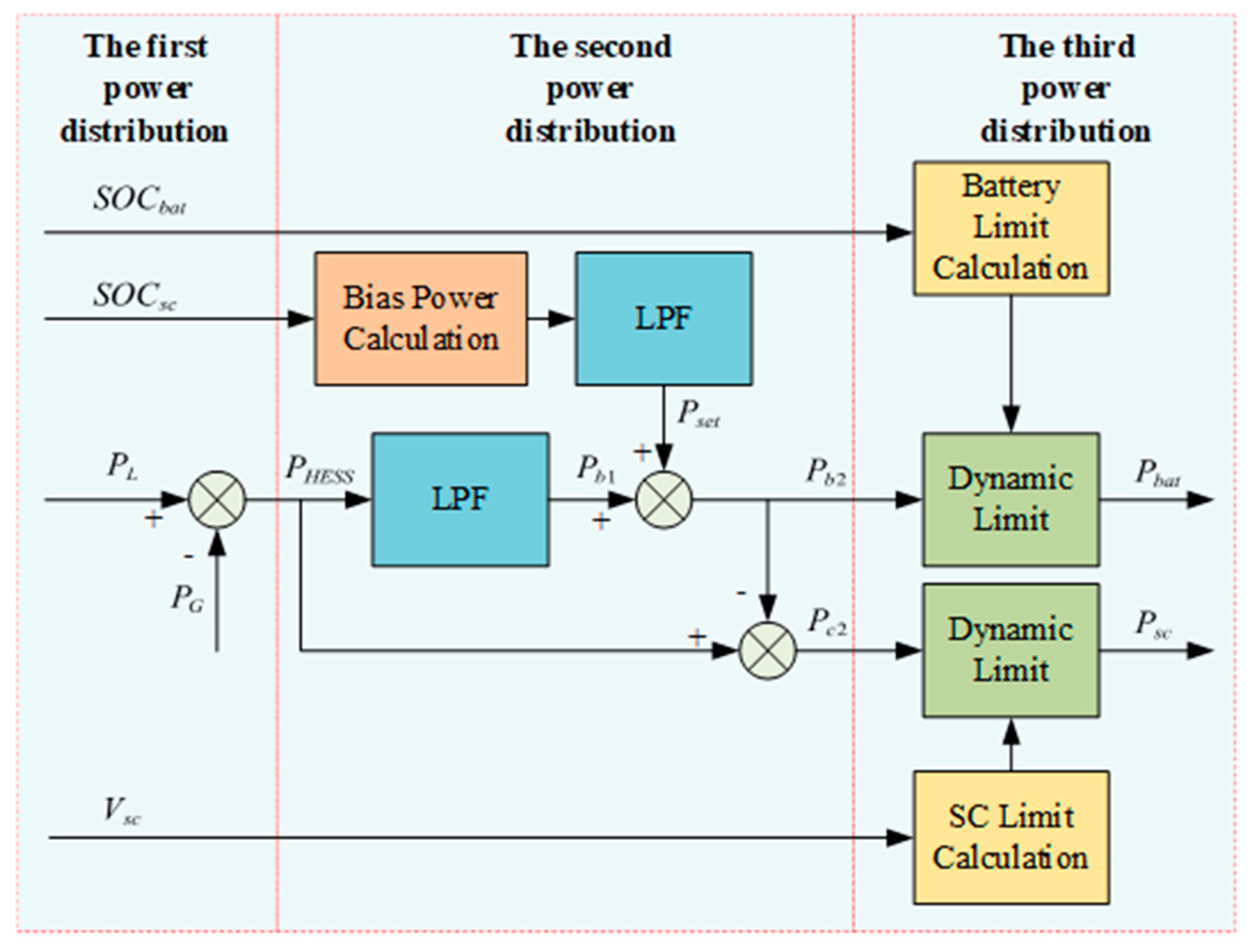
3.2.5. Power Distribution Process
Frequent fluctuations of the generator power will increase the loss of the system, and the basic function of the HESS is to cut peaks and fill valleys. To smooth the output power of the generator, under the premise of ensuring that the output power of the generator is maintained in the best working state, this paper proposes a three-step power distribution control strategy to realize the energy optimization management of the HESS. In the first step, the load current feedback control makes the bus voltage quickly return to stability. The initial allocation process is the difference between the generator output power
and the load demand power
to obtain HESS power
:
The second power distribution process is specifically as follows: First, the low-frequency component of the hybrid energy storage system power
is distributed to the battery through the LPF, and the high-frequency component and the impact power of the hybrid energy storage system
is distributed to the super capacitor:
Combined with the super capacitor SOC automatic recovery strategy, a bias value
is added to the above power to obtain the reference power of the battery
and the reference power of the super capacitor
:
The specific process of the third power allocation is to prevent the energy storage device from exceeding its maximum charge and discharge power limit, as the second allocation of power is limited. The final distribution power of the battery
and the super capacitor
is:
Among them,
,
are the upper and lower limits of battery charging and discharging power respectively, and
,
are the upper and lower limits of super capacitor charging and discharging power respectively. Due to the existence of the dynamic limiting strategy, the power limiting value is not constant. The schematic diagram of the tertiary power distribution is shown in
Figure 8.
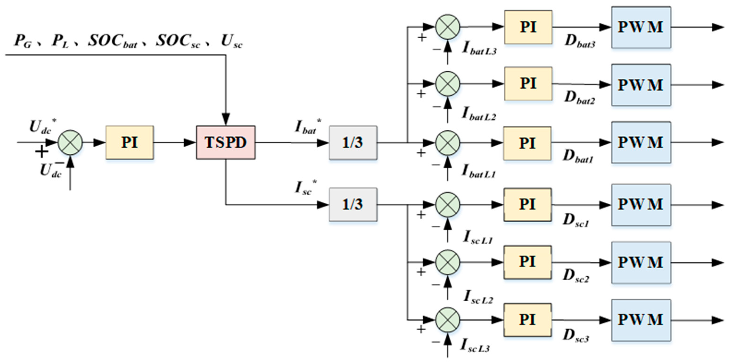
3.3. The Proposed EMS Control Process
This paper conducts research based on a three-step power distribution. The proposed EMS mainly includes the DC bus voltage outer loop, three-step power distribution, and three-current inner loop current sharing control. Among them, the DC bus voltage outer loop makes the bus voltage maintain at the rated value, and the TSPD realizes the reasonable distribution of the power of the hybrid energy storage system. The three-current inner-loop current sharing control enables the converter to accurately respond to the given current value to prevent the three-phase imbalance of the inductor current of the converter. The specific control process is as follows shown in
Figure 9.
4. Simulation
This paper uses a 60 kW power level distributed electric propulsion aircraft prototype as a benchmark to build a simulation model. Filter coefficient is set to 0.15 s [
14]. The simulation parameters of each part of the system are shown in
Table 1.
4.1. Sudden Loading and Unloading Simulation
The sudden loading and unloading operation of high-power loads is relatively common during aircraft operation, especially in combat mode, which will cause serious interference to the DC bus voltage and affect the quality of the power supply. Therefore, we first simulate this typical operating condition. The system first runs normally at a power level of 60 kW, and a load of 20 kW power is suddenly increased at 6 s, and the load is suddenly removed at 7 s. The load power waveform is as shown in
Figure 10a.
It can be seen from the
Figure 10b that HESS can effectively reduce the power demand of the generator and make the generator respond to the average value of load power fluctuations, otherwise the generator power will inevitably follow the load power.
Figure 10c shows the waveform of the bus voltage in the case of sudden loading and sudden unloading under the three control strategies, which are no HESS, traditional LPF, and the TSPD control strategy proposed in this article. Under TSPD, the bus voltage decreases by 11 V when the load suddenly increases and increases by 12 V when the load suddenly decreases. The fluctuation is less than 10%, and then quickly returns to stability. The recovery time is less than 10 ms, indicating that HESS can effectively compensate for the load power and reduce the fluctuation of the DC bus. The voltage stability is improved more than other strategies and realizes the optimization of the APS.
From
Figure 10d, we can see that whether it is a sudden load increase or a sudden decrease. The supercapacitor current change rate is always higher than that of the battery, which shows the supercapacitor responds to the instantaneous impact power of the system, and the battery compensates for the low-frequency power shortage, which further illustrates the effectiveness of power allocation.
4.2. Simulation of Super Capacitor SOC Automatic Recovery Strategy
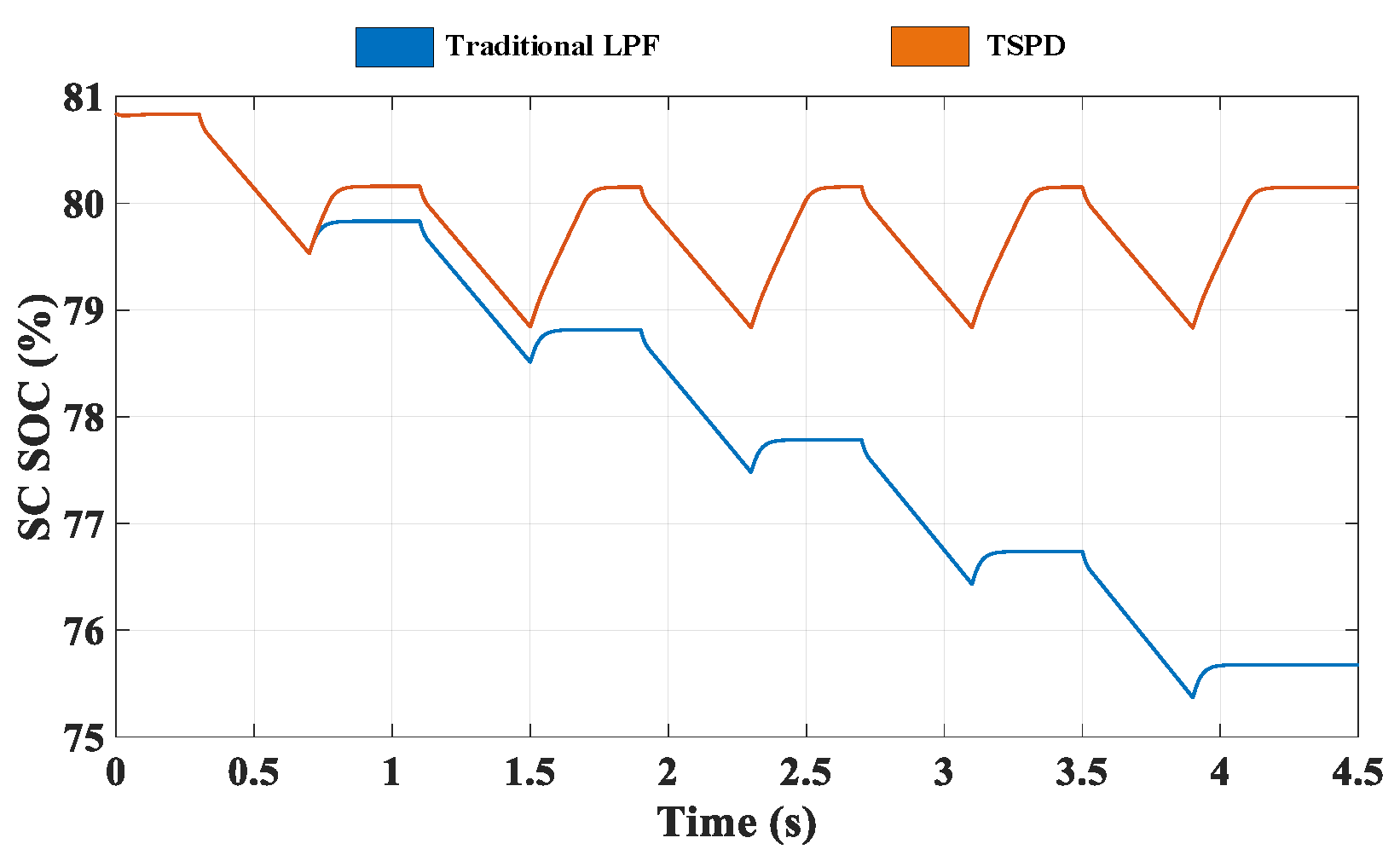
The lack of low energy density can be overcome by introducing a supercapacitor SOC automatic recovery strategy. Set the ideal working area of the super capacitor to 80%. The load is set as a periodic pulse load on the aircraft, which is mainly absorbed by the super capacitor. Observe the change of supercapacitor SOC under traditional LPF and TSPD control strategies.
It can be seen from
Figure 11 that supercapacitor SOC has been maintained at more than 80% under TSPD, while its SOC drops rapidly under the control of traditional LPF and will eventually lose its ability to smooth load fluctuations. In airplanes with severe space constraints, it is obviously of great significance to keep the super capacitor SOC at a level that can cope with the next power shock, avoid the limitation of low power of the super capacitor, and indirectly optimize the size of the HESS.
4.3. Dynamic Limiting Simulation
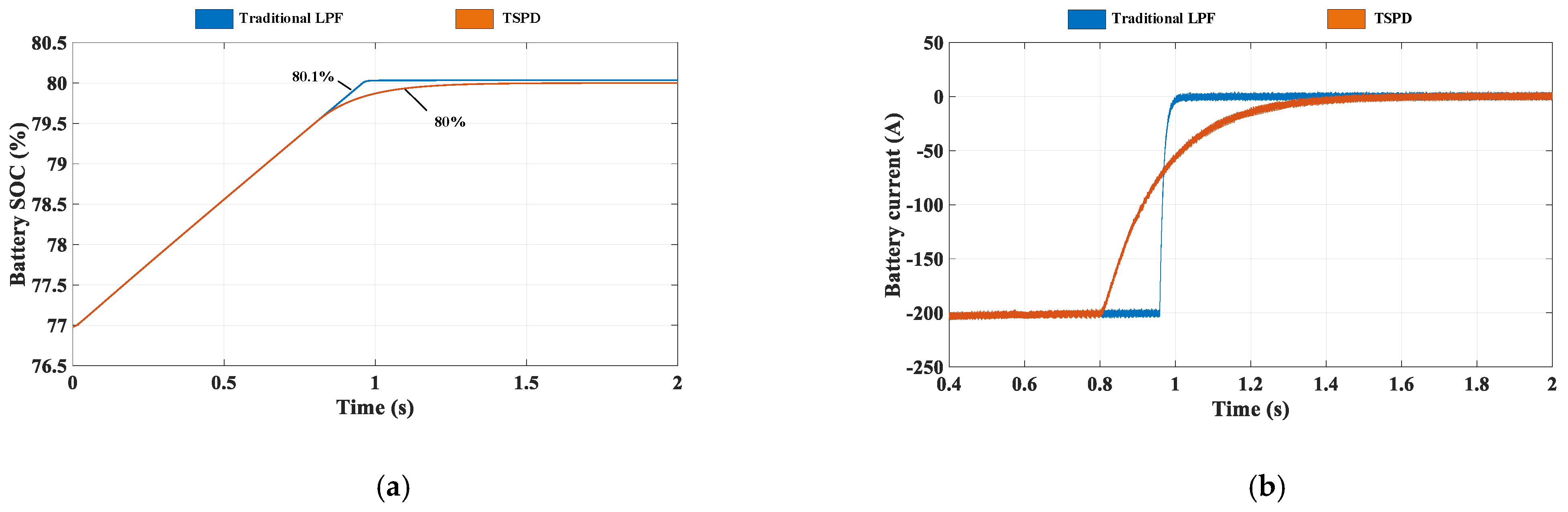
The overcharge and over discharge of the power will seriously reduce the service life of the ESD, and the allocated power must be limited, and this phenomenon can be effectively avoided by introducing a dynamic limiting strategy. In the simulation, the battery is charged with a current of 200 A (this phenomenon exists when the generator power is greater than the load consumption power).
It can be seen from
Figure 12 that the battery charging current is 200 A at the beginning, but when the battery SOC enters the charging warning zone, the charging current is limited, and finally the current is exactly 0 when it reaches 80%, while traditional LPF is over 80%. On the one hand, this realizes the constant current and constant voltage charging function of the battery. On the other hand, it avoids the occurrence of overcharging and prolongs the service life of the battery, because if you continue to charge with high current, the battery SOC will inevitably enter the charging prohibition zone and cause harm. Therefore, the proposed strategy prolongs the service life of the battery.
5. Experimental Verification
To further verify the proposed energy management strategy, the distributed electric propulsion aircraft test prototype built is shown in
Figure 13.
5.1. Sudden Loading and Unloading Experiment
To simplify the experiment, no generator is added. Take sudden addition and unloading of 20 kW power load as an example. The SOC of ESD is within the normal range. The experimental results are shown in
Figure 14, where
and
in the
Figure 14a are the operating current of the battery and the super capacitor respectively, and
is the load current.
It can be seen that when the load is suddenly applied, the super capacitor takes on the high-frequency power in the HESS through rapid discharge to slow down the drop of the DC bus voltage, while the change of the battery discharge current is relatively slow. When the load is suddenly unloaded, the super capacitor takes on the high-frequency power in the HESS through rapid charging to slow the rise of the DC bus voltage, while the change of the battery charging current is relatively slow.
Figure 14b shows the fluctuation of the bus voltage when the load is suddenly applied. The bus voltage drops by 15 V, and the recovery time is 22 ms.
Figure 14c shows the fluctuation of the bus voltage when the load is suddenly unloaded. The bus voltage rises by 13 V, and the recovery time is 20 ms. In general, the bus voltage fluctuation is less than 10%, indicating that HESS can effectively compensate the load power, reduce the fluctuation of the DC bus, and maintain voltage stability. Compared with the traditional control strategy, the TSPD method in this paper greatly reduces the time for the voltage to recover and stabilizes, and it also has certain advantages in reducing the degree of bus voltage drop. There is a battery charging the super capacitor in the second half of the current waveform, because the SOC of the super capacitor is less than 80%, which triggers the automatic recovery mechanism of the super capacitor SOC. This strategy is verified in detail below.
5.2. Super Capacitor SOC Automatic Recovery Experiment
When the state of charge of the super capacitor is lower than 80%, set the expected working area of the super capacitor to 80%, and observe the change of battery current, super capacitor current and super capacitor SOC. As can be seen in
Figure 15, since the SOC of the super capacitor is lower than 80%, the battery charges the super capacitor until the SOC of the super capacitor reaches 80%. Then, the battery stops discharging, indicating that the automatic recovery control strategy of the super capacitor SOC is reasonable and feasible, which ensures the power of the supercapacitor is maintained in the best state and can cope with the impact of high-power loads compared with the traditional control strategy.
At the same time, it can be seen from the figure above that the charging current begins to decrease at 15 s, which is because the dynamic limiting strategy starts to work. When it is close to the ideal value, the charging and discharging current is limited, effectively avoiding the occurrence of overcharge and over discharge.
6. Conclusions
Aiming at the problem of severe DC bus voltage fluctuations caused by frequent changes in the load of DEPA, this paper uses the hybrid energy storage system as a carrier to propose an energy management strategy for HESS based on TSPD, and builds a simulation and experimental platform to prove the effectiveness of the proposed method. The following conclusions can be drawn from the research.
1. The EMS proposed in this paper can give full play to the complementary characteristics of HESS. The battery responds to the low-frequency power of the load and the supercapacitor responds to the high-frequency power, which effectively improves the steady-state and dynamic performance of the DC bus voltage and improves the electrical quality of the system.
2. The proposed control strategy makes full use of the super capacitor, overcomes its low energy density, optimizes the size of the HESS, and extends the service life of ESD to a certain extent.
3. The proposed strategy smooths the generator output power fluctuation, reduces the generator’s capacity demand, and realizes the optimized management of the power supply system.
The low-pass filtering method has always been a relatively mature technology, which is effective in real-time applications, but it also has some limitations, such as the internal power cycle of the HESS and the small amount of high-frequency power fluctuations in the low-frequency power. Further improvements are needed in this research.
Author Contributions
Conceptualization, H.L. and T.Y.; methodology, H.L.; software, H.L. and L.W.; validation, H.L., F.B., X.Z. and L.W.; formal analysis, H.L.; investigation, T.Y. and F.B.; resources, T.Y. and X.Z.; data curation, H.L.; writing—original draft preparation, H.L.; writing—review and editing, F.B.; visualization, H.L.; supervision, T.Y.; project administration, F.B.; funding acquisition, T.Y. All authors have read and agreed to the published version of the manuscript.
Funding
This research was funded by the Nanjing University of Aeronautics and Astronautics (NUAA) and AECC Aero Engine Control System Institute.
Data Availability Statement
The data presented in this study are available on request from the corresponding author. The data are not publicly available due to the commercial secret.
Acknowledgments
The authors wish to thank the Nanjing University of Aeronautics and Astronautics (NUAA) and AECC Aero Engine Control System Institute for the assistance that enable the research.
Conflicts of Interest
The authors declare no conflict of interest.
References
- Zhang, Z.; Lu, J.; Li, J.; Yu, L. Review of electric power system of distributed electric propulsion aircraft. Acta Aeronaut. 2018, 39, 46–62. [Google Scholar]
- Zaporozhets, O.; Isaienko, V.; Synylo, K. Trends on current and forecasted aircraft hybrid electric architectures and their impact on environment. Energy 2020, 211, 118814. [Google Scholar] [CrossRef] [PubMed]
- Xu, Q.; Zhang, C.; Xu, Z.; Lin, P.; Wang, P. A Composite Finite-Time Controller for Decentralized Power Sharing and Stabilization of Hybrid Fuel Cell/Supercapacitor System with Constant Power Load. IEEE Trans. Ind. Electron. 2021, 68, 1388–1400. [Google Scholar] [CrossRef]
- Barzkar, A.; Ghassemi, M. Electric Power Systems in More and All Electric Aircraft: A Review. IEEE Access 2020, 8, 169314–169332. [Google Scholar] [CrossRef]
- Wang, Y.; Xu, F.; Mao, S.; Yang, S.; Shen, Y. Adaptive Online Power Management for More Electric Aircraft with Hybrid Energy Storage Systems. IEEE Trans. Transp. Electrif. 2020, 6, 1780–1790. [Google Scholar] [CrossRef]
- Chen, J.; Song, Q.; Yin, S.; Chen, J. On the Decentralized Energy Management Strategy for the All-Electric APU of Future More Electric Aircraft Composed of Multiple Fuel Cells and Supercapacitors. IEEE Trans. Transp. Electrif. 2020, 67, 6183–6194. [Google Scholar] [CrossRef]
- Sankarkumar, R.S.; Natarajan, R. Energy management techniques and topologies suitable for hybrid energy storage system powered electric vehicles: An over-view. Int. Trans. Electr. Energy Syst. 2021, 31, e12819. [Google Scholar] [CrossRef]
- Zhang, W.; Xia, Y.; Xu, D.; Bi, K.; Yang, W. Command-filtered backstepping controller for DC microgrid with hybrid energy storage devices. In Proceedings of the 2020 IEEE 9th Data Driven Control and Learning Systems Conference (DDCLS), Liuzhou, China, 20–22 November 2020; pp. 865–869. [Google Scholar]
- Xiao, Z.-X.; Li, H.-M.; Fang, H.-W.; Guan, Y.-Z.; Liu, T.; Hou, L.; Guerrero, J.M. Operation Control for Improving Energy Efficiency of Shipboard Microgrid Including Bow Thrusters and Hybrid Energy Storages. IEEE Trans. Transp. Electrif. 2020, 6, 856–868. [Google Scholar] [CrossRef]
- Wu, T.; Yu, W.; Guo, L. A Study on Use of Hybrid Energy Storage System Along with Variable Filter Time Constant to Smooth DC Power Fluctuation in Microgrid. IEEE Access 2019, 7, 175377–175385. [Google Scholar] [CrossRef]
- Lu, S.; Wu, L.; Li, S.; Wei, G. Zero Voltage Switching N-Type Interleaved Three-Level Bidirectional DC-DC Converter. Trans. China Electrotech. Soc. 2020, 35, 461–469. [Google Scholar]
- Fu, J.; Guo, K.; Yan, D. An improved low pass filter strategy for hybrid energy storage system of based on simplified ADRC. J. Xi’an Polytech. Univ. 2020, 34, 80–85. [Google Scholar]
- Hou, J.; Sun, J.; Hofmann, H.F. Mitigating Power Fluctuations in Electric Ship Propulsion with Hybrid Energy Storage System: Design and Analysis. IEEE J. Ocean. Eng. 2018, 43, 93–107. [Google Scholar] [CrossRef]
- Cheng, L.; Zhang, F.; Xie, M.; Wang, Y.; Zou, H. High power density optimal configuration for hybrid energy storage system based on equivalent time. Acta Aeronaut. 2018, 39, 322129. [Google Scholar]
| Publisher’s Note: MDPI stays neutral with regard to jurisdictional claims in published maps and institutional affiliations. |
© 2021 by the authors. Licensee MDPI, Basel, Switzerland. This article is an open access article distributed under the terms and conditions of the Creative Commons Attribution (CC BY) license (https://creativecommons.org/licenses/by/4.0/).


