Article

Single-Phase Active Power Harmonics Filter by Op-Amp Circuits and Power Electronics Devices

1
Department of Electronics Design (EKS), Mid Sweden University, Holmgatan 10, 85170 Sundsvall, Sweden
2
Department of Engineering, Atlas Danesh Co, Ghaemshahr 47658-37449, Iran
3
Engineering Faculty, University of Mazandaran, Babolsar 47416-13534, Iran
4
C-MAST, University of Beira Interior, 6201-001 Covilhã, Portugal
5
Department of Electrical Engineering and Automation, Aalto University, 02150 Espoo, Finland
*
Authors to whom correspondence should be addressed.
Sustainability 2018, 10(12), 4406; https://0-doi-org.brum.beds.ac.uk/10.3390/su10124406
Submission received: 2 November 2018 / Revised: 19 November 2018 / Accepted: 23 November 2018 / Published: 26 November 2018
(This article belongs to the Special Issue Sustainable Energy Systems: From Primary to End-Use)

Abstract

:
This paper introduces a new structure for single-phase Active Power Harmonics Filter (APHF) with the simple and low-cost controller to eliminate harmonics and its side effects on low voltage grid. The proposed APHF includes an accurate harmonic detector circuit, amplifier circuit to trap tiny harmonics, switching driver circuit for precise synchronization, and inverter to create injection current waveform, which is extracted from reference signal. The control circuits are based on electrostatic devices consist of Op-Amp circuits. Fast dynamic, simplicity, low cost, and small size are the main features of Op-Amp circuits that are used in the proposed topology. The aim is removing the all grid harmonic orders in which the proposed APF injects an appropriate current into the grid in parallel way. The proposed control system is smart enough to compensate all range of current harmonics. A prototype is implemented in the power electronics laboratory and it is installed as parallel on a distorted grid by the non-linear load (15 APeak-Peak) to verify the compensating of harmonics. The harmonics are compensated from THD% = 24.48 to THD% = 2.86 and the non-sinusoidal waveform is renovated to sinusoidal waveform by the proposed APHF. The experimental results show a good accurate and high-quality performance.

1. Introduction

The growth of applying for semiconductor devices and nonlinear loads in industrial, residential, and commercial areas has led to the destruction of power grid voltage and current waveforms in which they cause harmonic distortion in the electrical system [1,2]. Harmonics in the electricity network make harmful damages, such as power losses, the overload in transmission lines, the reduction of the power quality, lower efficiency in equipment, and disturbance in the performance of devices [3,4,5,6].
Therefore, the detection of harmonics and finding a strategy are essential to eliminate and reduce them down to standard allowed. During many years, passive filters have been the conventional solution to minimize harmonics pollution [7,8,9,10,11]. There are many power factor correctors (PFC) converters with the ability to reduce harmonics as well. Family of single-phase and hybrid PFC buck-boost converters are introduced in [12,13]. In [14], three-level unidirectional single-phase PFC rectifier topologies are presented. Some other topologies discussed the range of output to develop PFC converters [15].
The PFC converter usually has low power factor (PF) and poor harmonic performance due to the inherent dead angle of the input current, especially at low input/output ranges [13]. Active power harmonic filters (APHFs) have been proposed as a power electronics solution, since passive filters have quite a few disadvantages [16,17,18,19]. The smart control ability of the active harmonic filters is a very prominent advantage [20]. As a best harmonic detective device, it can be installed at various scales along with harmonic loads to prevent the spread of harmonics into the grid, so that the network remains in its sinusoidal waveform [21,22,23,24]. The vast applications of this device are effective to increase network power quality [25,26,27,28,29,30]. The active filters produce the same amount (but opposite) of harmonic by monitoring the harmonics of electrical load current that forbid the current harmonics to flow through the power line [31,32].
The active power harmonic filter as compensator is divided into two parts: (1) power circuit; and, (2) control circuit (Harmonic Detector Algorithm for control of switching). The defect in each section and unsuitable connection not only lead to compensative performance but also increase the harmonic components that reduce the power quality [33]. The accurate algorithm of the harmonic detector and switching pattern can lead to a reduction in the cost of the power part structure. Hence, there are many articles in the control, harmonic detection, and switching pattern. Most articles discuss the control circuits based on programming, especially the transfer function and DQ-axis (direct-quadrature) transformations [34,35,36,37,38]. Search algorithms have been used as well [39,40]. The authors in [41] investigate the prediction on the harmonic load for control of the power quality. Although microprocessors will reduce the complexity of control circuits, but the decrease in quality of sampling signals due to the analog/digital converting, some inefficient coding algorithm, slower response to non-complex calculations, and expensive cost than electrostatic circuits should be considered [42,43,44]. On the other hand, fast response in electrostatic circuits for non-complex calculations and low-cost than microprocessors can increase the performance of the control circuit. In addition, the removing of microprocessors makes a simpler circuit in which the decreasing in the total cost of the implementation would be expected [45,46,47,48]. Another important challenge in APHF is switching and synchronizing with the current grid. More damages in the network are expected without the accurate synchronization of the reference signal. Fast switching and accurate synchronization are some features of the hysteresis switching technique that are used in the high-speed electrostatic circuit [49,50].
In this paper, the control strategy of active harmonics filter is presented by electrostatic devices and Op-Amp circuits that cause the removal of microprocessors and programming devices. The removing of microprocessors declines the complication of programming and analog/digital converting and its quality distortion in sampled signals for APHF. The voltage sensor (sampling) is also removed in the proposed control strategy due to hysteresis switching with a precise synchronization. Thus, the cost of implementation can be reduced, although the performance quality is increased by the fast dynamic response and accurate harmonics elimination. Proposed topology can be used by residential, commercial, and small industries electricity consumers. The operation of the proposed controller follows as: the load current is being sensed by a current sensor that is infected by harmonics. Then, harmonics are extracted by proposed Op-Amp circuits with a fast dynamic response. The extracted signals are boosted in amplifier circuit since the tiny high-order harmonics can be considered in switching pattern. It significantly increases the quality of the APHF compensation. Section 2 illustrates these issues. Hysteresis and synchronization are described in Section 3. Experimental results are shown in Section 4 to verify the high performance of different parts of the proposed controller circuit and the compensation of APHF.

2. The Strategy of Harmonics Detection

Some properties in control circuit should be considered, such as the smart extraction of harmonics, the pitch adjustment in magnitude and phase for the reference signal, the remaining quality in fundamental harmonic order (1st) after APFH operation, and simple structure. The perfect performance of each these properties lead to proper overall results in APHF.
Figure 1 presents a simple and high quality schematic for a high-pass filter with the exact pitch adjustment to extract grid harmonics. The sampled signal (from the grid by the current sensor) has been sent to the proposed circuit through Vin and the circuit acts as a high-pass filter that is based on the values of the capacitor and resistors. Consequently, it separates all of the harmonics that are higher than the cutoff frequency and the circuit reveals them in output (Vout). The output signal will be used as a reference signal for switching part.
This proposed circuit involves op-amp devices. Other electronic devices (resistors, capacitors, diode, etc.) with different arrangements can be joint to op-amp, in order to use in various operation and applications. This high pass filter is designed based on op-amp devices and cutoff frequency is set to separate frequencies higher than fundamental component. This circuit has a very accurate operation in the category of electrostatic filters in which it reveals all the harmonics higher than the cutoff frequency with high quality. Also, another prominent property is the adjustment of the phase between input and output signal by correct design. This feature is used to synchronize the reference signal with the network current.
Equations are extracted to drive the transfer function of the proposed filter for Figure 1, follows as:
The KCL in node X can be written as:
I i n = I R 1 + I C 1
That I i n , I R 1 , and I C 1 are the input current, the current passing through the resistance R1 and the current passing through the capacitor C1, respectively.
The currents in the op-amp legs are zero, thus:
I R 2 = I C 1
When considering the voltage of point X (Vx), the above equation can be rewritten:
V x = 1 + R 2 C 1 s R 2 C 1 s   V o u t
It is also possible to write the current of branches according to the voltage of point X:
I i n = V i n V x 1 s C 2
I C 1 = V O u t R 2
I R 1 = V x V O u t R 1
By putting above equations in (1) and solving of the equations in the Laplace domain, the transfer function of the circuit can be calculated, as follows:
V O u t V i n = s 2 s 2 + C 1 + C 2 R 2 C 1 C 2 + 1 R 1 R 2 C 1 C 2
According to the (7), the transfer function of the circuit is second-order that increases the slop of cutoff frequency and the quality of the output signal as well.
In some harmonic orders, the magnitude of the detected harmonic is low (especially higher-order harmonics), so that it cannot trigger the switching system to remove harmonics by power part. Then, it is necessary to amplify the harmonic orders to increase the accuracy of reference signal. The circuit which is depict in Figure 2 is used as the amplifier circuit [51].

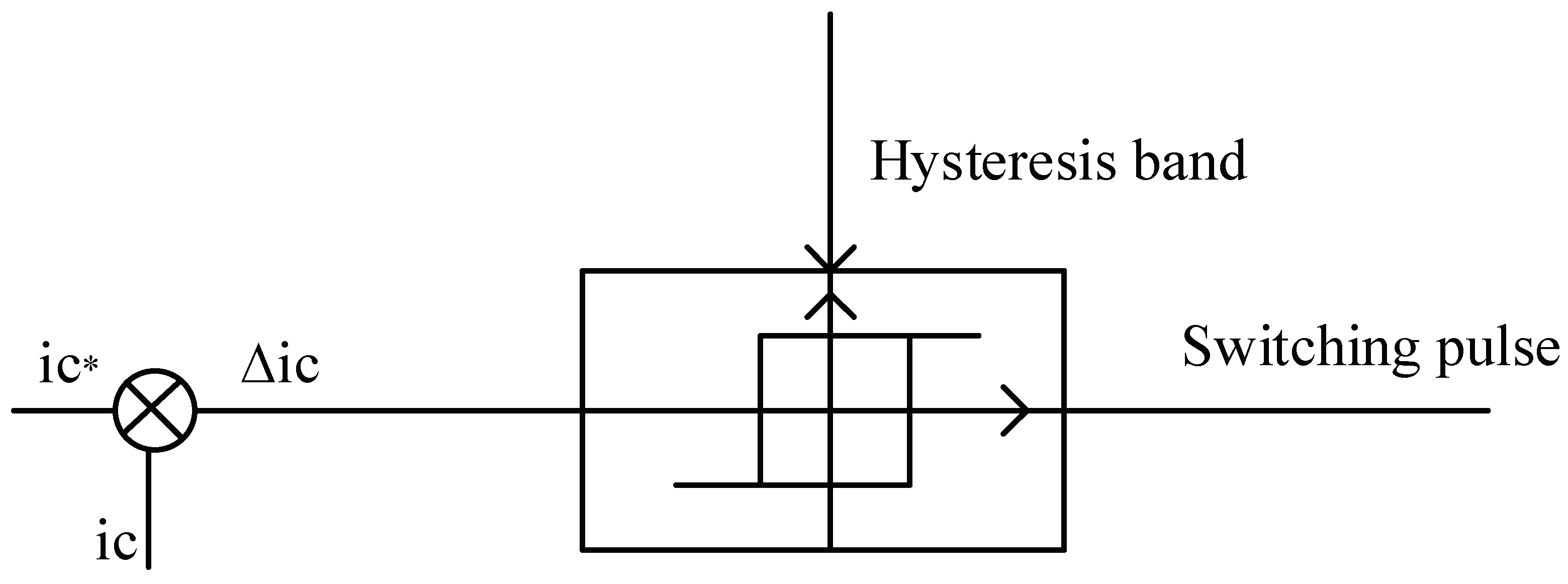
Hysteresis Switching Technique (HYS)

The hysteresis switching technique is more interesting due to some futures such as fast response, less complexity and independence from an additional reference signal (for example triangular wave in PWM Technique) [52]. Grid connection with easy synchronization mood is an outstanding of this Technique. Figure 3 shows the block diagram operation of hysteresis pulse generation. As shown in Figure 3, the reference current which obtained by the detector algorithm ( i * c ) is compared with the output current of the active filter brunch ( i c ) and the error due to the difference between these is sent to the fixed hysteresis band. There are two pair group switches for switching, since the active power filter use H-bridge circuit. The group switches work as a cross-pair in the H-bridge. The hysteresis technique is used for both group switches for positive and negative currents. It also has a dead time between the switching.
A constant bandwidth is surrounding the reference signal. If the error value (Δ i c ) is higher than the upper band the switch will be off, and if the error value is lower than the lower band, then the switch will be turned on. The operation of the switch between the upper and lower bands for the sinusoidal reference signal is shown in Figure 4.

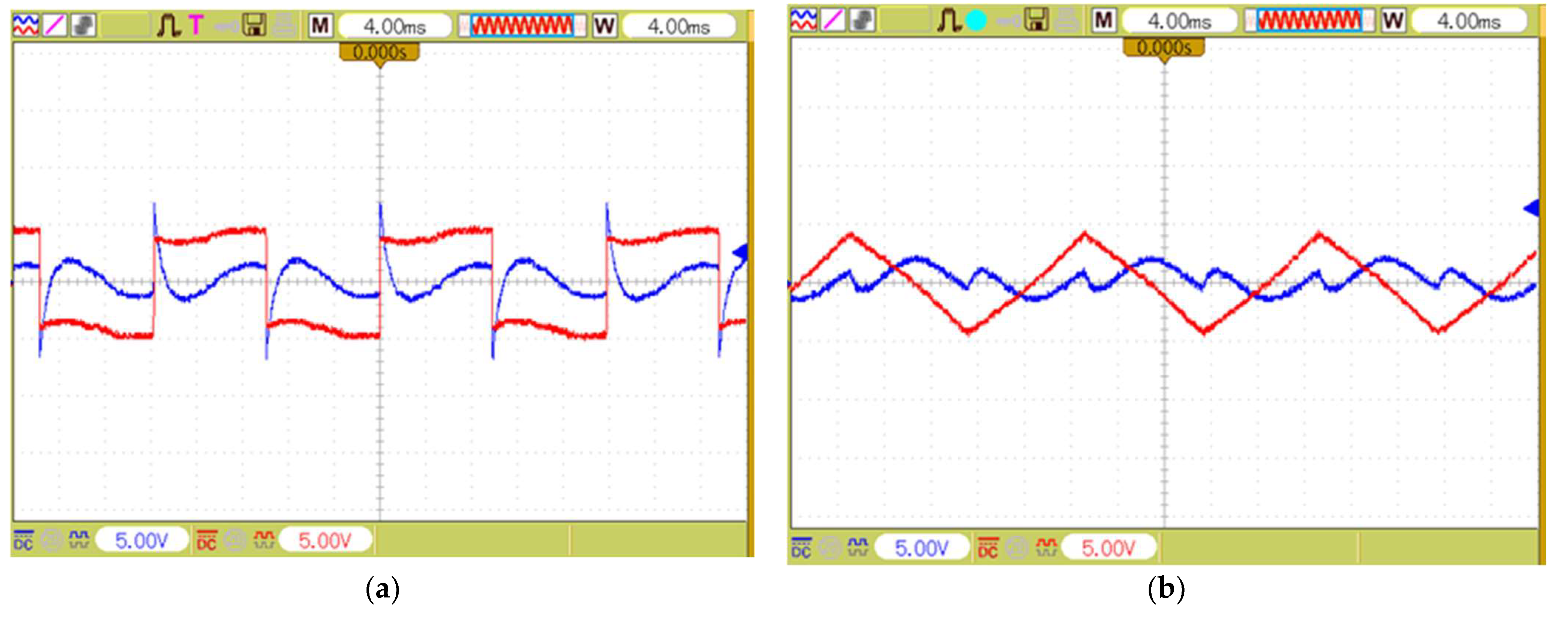
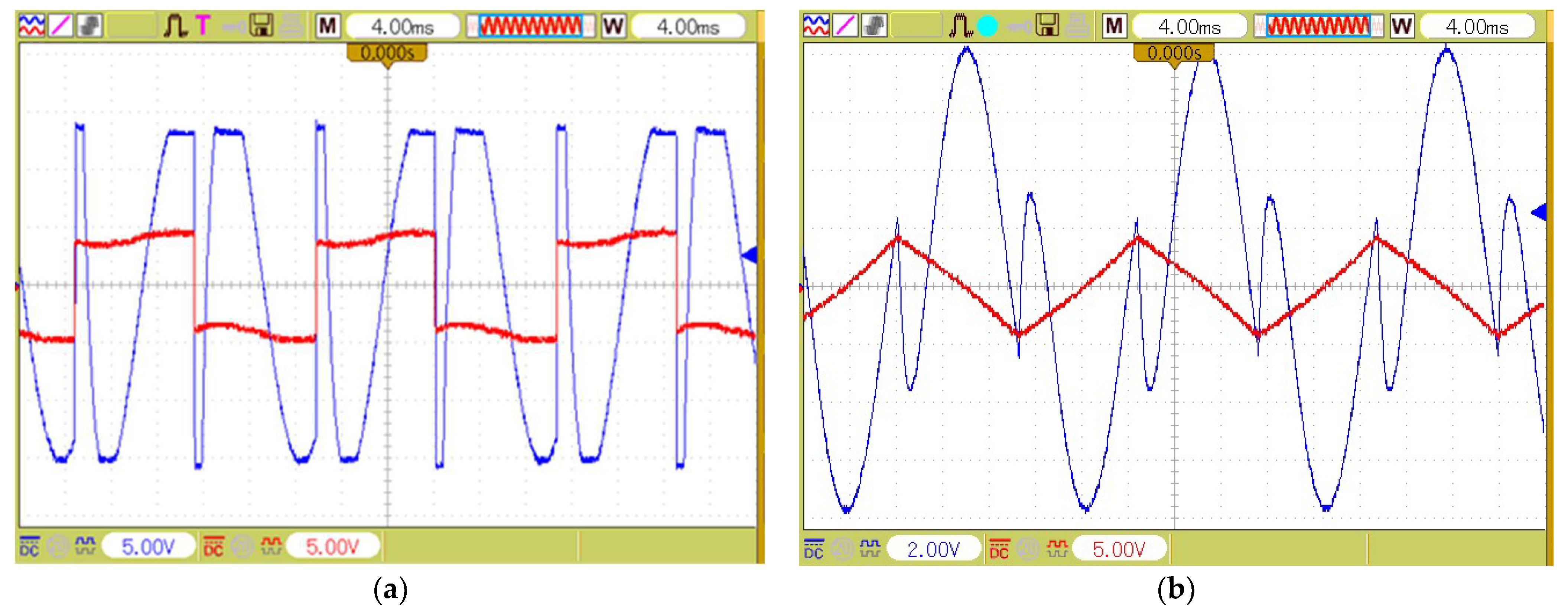
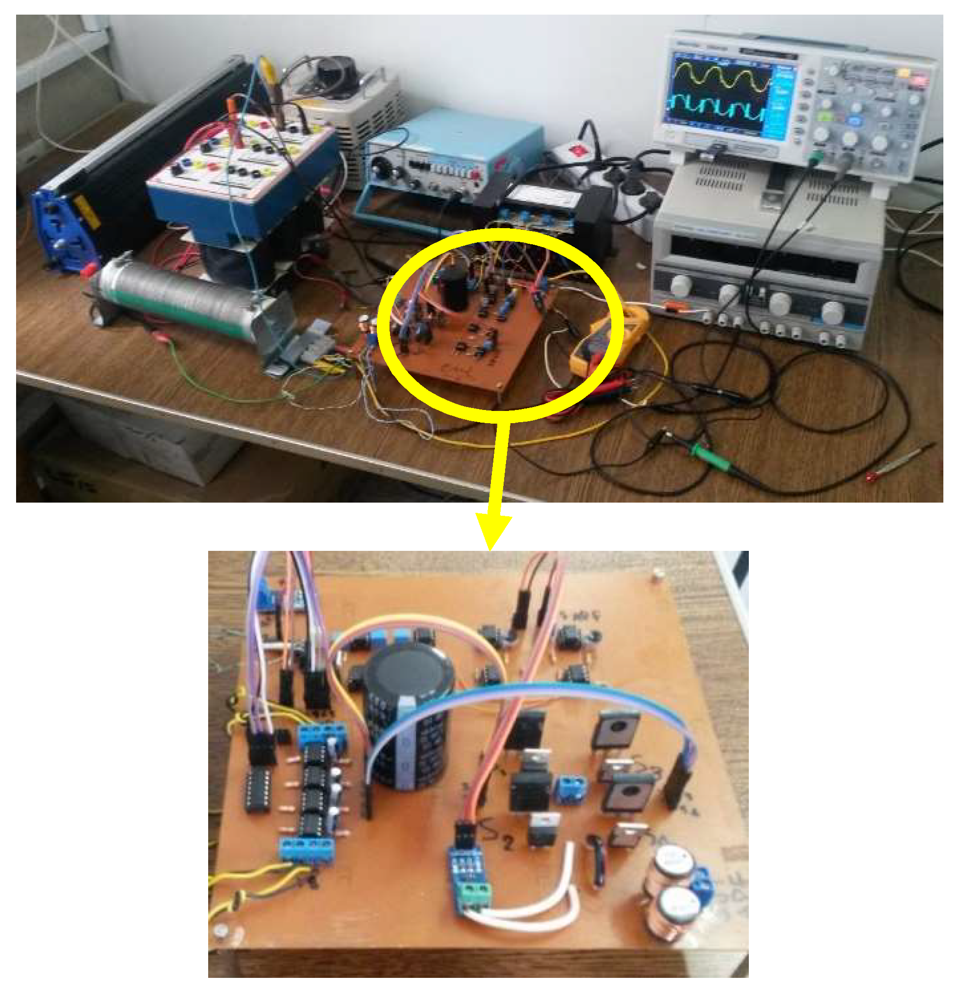
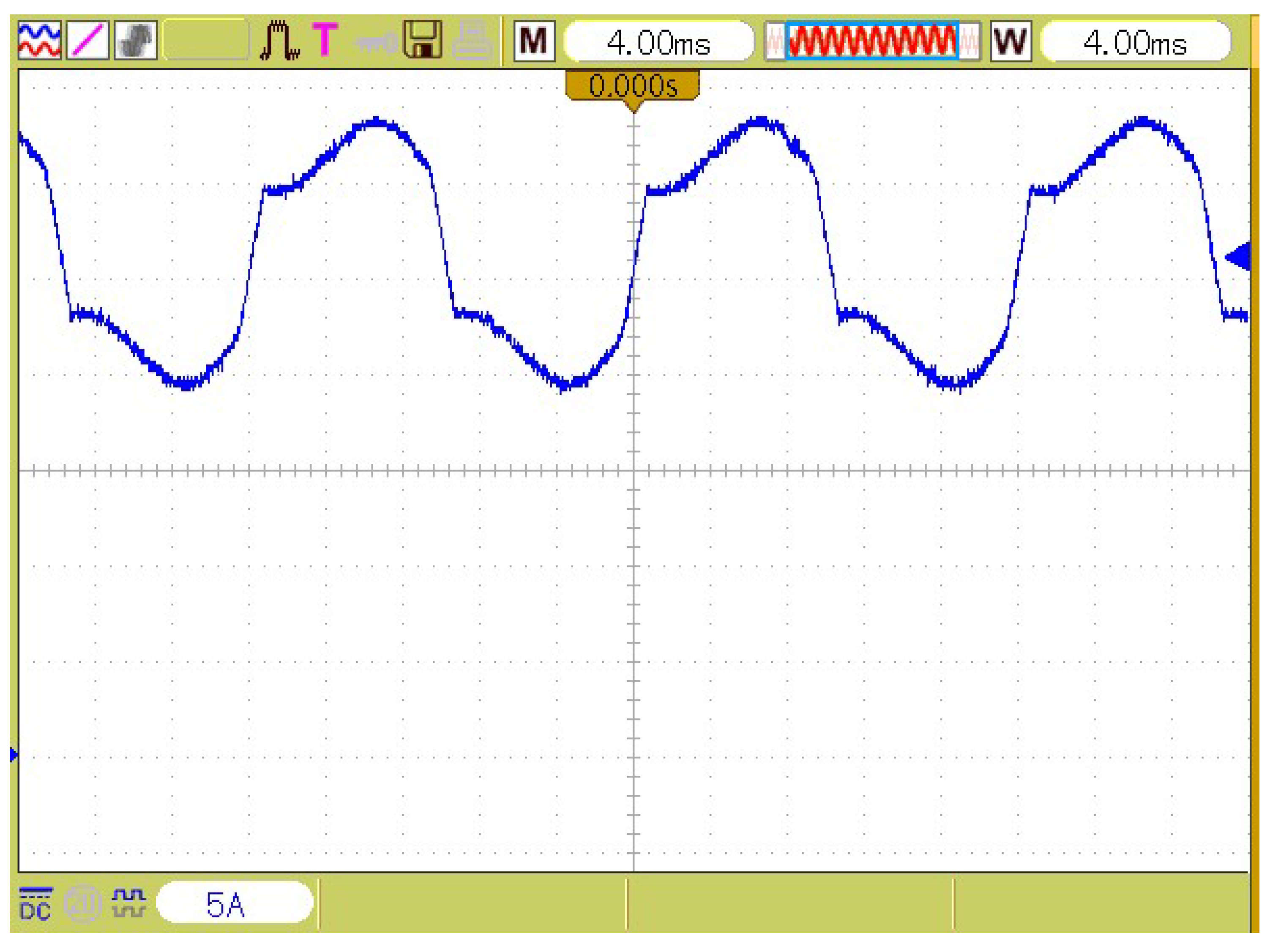
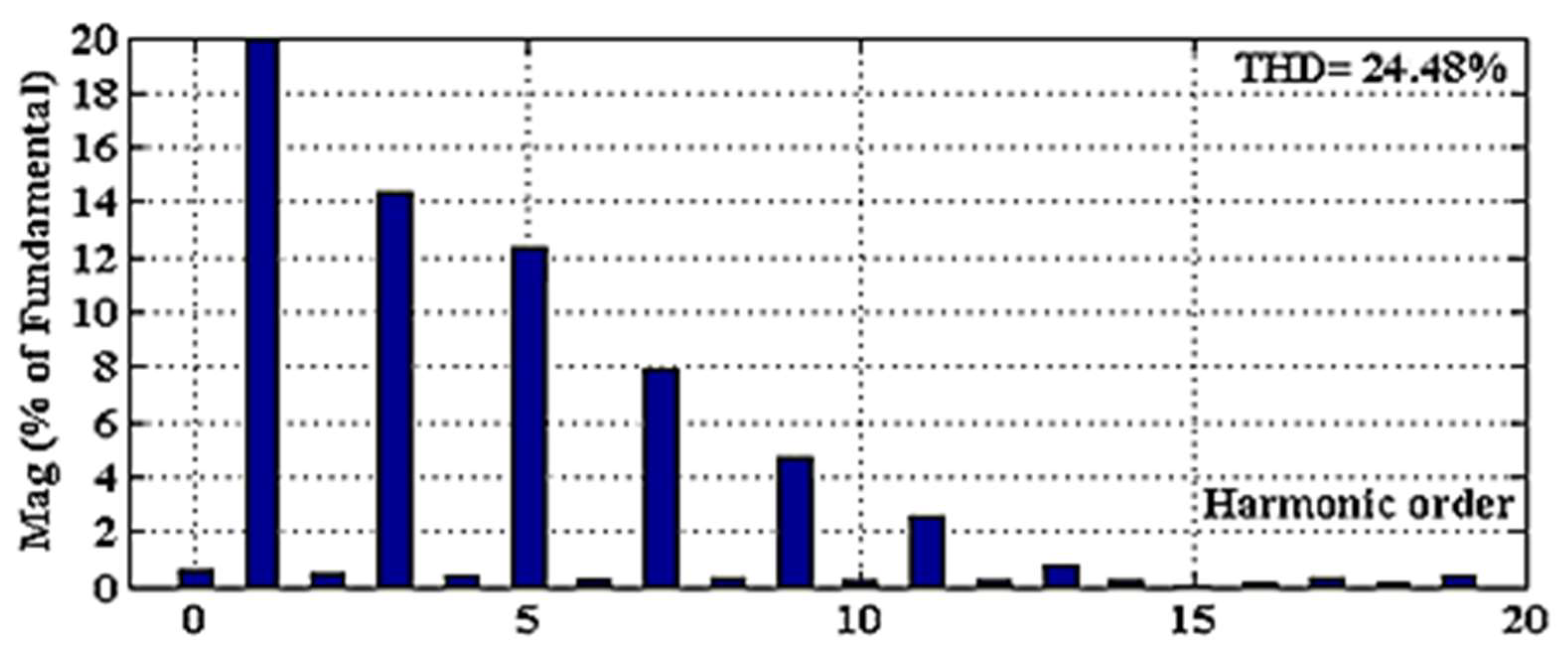
3. Experimental Results

A prototype of active power filter is designed in the laboratory to verify the compensative operation of APHF in order to eliminate the grid harmonics. Figure 5 illustrates the configuration of the study system and the properties and the values of the elements are presented in Table 1.
As shown in Figure 5, a diode-bridge connected with induction and resistor are considered as a non-linear load and they are supplied through the grid. Inductance is used in this system to protect the short circuit between APF and grid as current damper since the APF works according to the current injection. The diode-bridge generates harmonics since it is used as a rectifier, and these harmonics should be supplied through the grid. The APHF is applied in load in parallel to compensate the harmonic and prevent the penetration of it in the grid. IGBT 12n60 and RHR 15120 are used as power electronics switches and diodes in the prototype setup.
The qualification of the extracted harmonics and synchronization switching are investigated. The two sample experimental signals (red colored) are depicted in Figure 6. In order to the accuracy of harmonics extraction of detector circuit (Figure 1). Figure 6a shows the input of semi-square signal and Figure 6b shows semi-triangle ones. Harmonics are exactly extracted from both input signals that reveal harmonic components (blue colored), except the fundamental frequency of 50 Hz. High operation quality of control circuit and accurate extraction of harmonics is obvious in figures.
The amplifier circuit (Figure 2) works properly in which Figure 7 shows the amplified waveform of Figure 6. It is noticeable that the APF injects current to compensate higher harmonics currents too. Thus, controller holds the amplifier in saturated mood, as shown in Figure 7a.
Figure 8 shows the bode and phase diagrams of the proposed control circuit. The cutoff frequency is set in 70 Hz to disappear the fundamental component in the output of the detector circuit for switching.
According to the Figure 8, the amount of phase and magnitude of harmonics are higher than the fundamental component (3rd, 5th, 7th, ⋯) passes accurately and unchanged in phase in the proposed controller. This property is very efficient to synchronize the APHF with the grid.
In order to increase the harmonic extraction quality, two series circuits are used to achieve fourth order high pass filter. The extracted and amplified harmonics will be sent to the op-amp comparator circuit to drive and trig power electronic switches. The proposed controller circuit is applied in the prototype system (Figure 9) and the results of evaluations are shown in Figure 10, Figure 11, Figure 12, Figure 13 and Figure 14 with and without APHF in grid connection.
Figure 10 illustrates the current waveform of the grid and Figure 11 shows its harmonic spectrum without APHF. Figure 12 and Figure 13 show the current waveform of the grid and its harmonic spectrum with APHF, respectively. According to the figures, non-sinusoidal waveforms turned to sinusoidal after applying APHF and the harmonics are reduced magnificently from THD% = 24.48 to THD% = 2.86. It is obvious that all orders are decreased under 5%, which satisfy standard IEEE 519.
The injection current of APHF is shown in Figure 14.
Figure 15 also illustrates the smooth voltage waveform of DC link (the capacitor of APHF). It is constant at 310 Volts.

4. Conclusions

This paper presented a new controller circuit with op-amp electrostatic circuit for active power harmonic filter. Simplicity, synchronization, and accurate operation are investigated on it. The proposed control system monitors the current of the grid and creates the reference signal and then inject appropriate current to prevent spreading of the load harmonic into the grid. Using the hysteresis switching technique with a precise synchronization made this proposed control system exhibit a fast response with less complexity. A prototype that uses this control circuit is implemented in the laboratory. In study system, the APHF is applied to the non-linear load in parallel with THD% = 24.48 that is supplied from the grid and THD% is reduced to %2.86 in the experimental results. Also, the non-sinusoidal waveform is renovated to sinusoidal waveform by proposed APHF. High operation quality of control circuit and the accurate extraction of harmonics confirm the good performance of the proposed controller.

Author Contributions

All authors contributed equally to this work and all authors have read and approved the final manuscript.

Funding

This research received no external funding.

Conflicts of Interest

The authors declare no conflict of interest.

References

  1. Singh, R.; Singh, A. Energy loss due to harmonics in residential campus—A case study. In Proceedings of the 45th International Universities Power Engineering Conference UPEC2010, Cardiff, UK, 31 August–3 September 2010; pp. 1–6. [Google Scholar]
  2. Simpson, R.H. Misapplication of power capacitors in distribution systems with nonlinear loads-three case histories. IEEE Trans. Ind. Appl. 2005, 41, 134–143. [Google Scholar] [CrossRef]
  3. Yazdani-Asrami, M.; Sadati, S.M.B.; Samadaei, E. Harmonic study for MDF industries: A case study. In Proceedings of the 2011 IEEE Applied Power Electronics Colloquium (IAPEC), Johor Bahru, Malaysia, 18–19 April 2011; pp. 149–154. [Google Scholar] [CrossRef]
  4. Gao, S.; Li, X.; Ma, X.; Hu, H.; He, Z.; Yang, J. Measurement-based compartmental modeling of harmonic sources in traction power-supply system. IEEE Trans. Power Deliv. 2017, 32, 900–909. [Google Scholar] [CrossRef]
  5. Grady, W.M.; Santoso, S. Understanding power system harmonics. IEEE Power Eng. Rev. 2001, 21, 8–11. [Google Scholar] [CrossRef]
  6. Samadaei, E.; Khosravi, A.; Sheikholeslami, A. Optimal Allocation of Active Power Filter On real distribution network for improvement of power quality by use of BBO: A case study. IIUM Eng. J. 2017, 18, 85–99. [Google Scholar] [CrossRef]
  7. Beres, R.N.; Wang, X.; Liserre, M.; Blaabjerg, F.; Bak, C.L. A review of passive power filters for three-phase grid-connected voltage-source converters. IEEE J. Emerg. Sel. Top. Power Electron. 2016, 4, 54–69. [Google Scholar] [CrossRef]
  8. Chang, G.W.; Chu, S.Y.; Wang, H.L. A new method of passive harmonic filter planning for controlling voltage distortion in a power system. IEEE Trans. Power Deliv. 2006, 21, 305–312. [Google Scholar] [CrossRef]
  9. Zobaa, A.F. The optimal passive filters to minimize voltage harmonic distortion at a load bus. IEEE Trans. Power Deliv. 2005, 20, 1592–1597. [Google Scholar] [CrossRef]
  10. Badrzadeh, B.; Smith, K.S.; Wilson, R.C. Designing passive harmonic filters for an aluminum smelting plant. IEEE Trans. Ind. Appl. 2011, 47, 973–983. [Google Scholar] [CrossRef]
  11. Chang, G.W.; Wang, H.L.; Chu, S.Y. Strategic placement and sizing of passive filters in a power system for controlling voltage distortion. IEEE Trans. Power Deliv. 2004, 19, 1204–1211. [Google Scholar] [CrossRef]
  12. Zhao, B.; Abramovitz, A.; Smedley, K. Family of bridgeless buck-boost PFC rectifiers. IEEE Trans. Power Electron. 2015, 30, 6524–6527. [Google Scholar] [CrossRef]
  13. Zhang, J.; Zhao, C.; Zhao, S.; Wu, X. A family of single-phase hybrid step-down PFC converters. IEEE Trans. Power Electron. 2017, 32, 5271–5281. [Google Scholar] [CrossRef]
  14. Lange, A.D.B.; Soeiro, T.B.; Ortmann, M.S.; Heldwein, M.L. Three-level single-phase bridgeless PFC rectifiers. IEEE Trans. Power Electron. 2015, 30, 2935–2949. [Google Scholar] [CrossRef]
  15. Liu, Y.; Sun, Y.; Su, M.; Zhou, M.; Zhu, Q.; Li, X. A Single-Phase PFC Rectifier with Wide Output Voltage and Low-Frequency Ripple Power Decoupling. IEEE Trans. Power Electron. 2018, 33, 5076–5086. [Google Scholar] [CrossRef]
  16. Akagi, H. Modern active filters and traditional passive filters. Bull. Pol. Acad. Sci. Tech. Sci. 2006, 54, 255–269. [Google Scholar]
  17. Wu, C.J.; Chiang, J.C.; Yen, S.S.; Liao, C.J.; Yang, J.S.; Guo, T.Y. Investigation and mitigation of harmonic amplification problems caused by single-tuned filters. IEEE Trans. Power Deliv. 1998, 13, 800–806. [Google Scholar] [CrossRef]
  18. Bhattacharya, S.; Cheng, P.T.; Divan, D.M. Hybrid solutions for improving passive filter performance in high power applications. IEEE Trans. Ind. Appl. 1997, 33, 732–747. [Google Scholar] [CrossRef]
  19. Peng, F.Z. Harmonic sources and filtering approaches. IEEE Ind. Appl. Mag. 2001, 7, 18–25. [Google Scholar] [CrossRef]
  20. Salam, Z.; Tan, P.C.; Jusoh, A. Harmonic’s mitigation using active power filter: A technological review. Elektr. J. Electr. Eng. 2006, 8, 17–26. [Google Scholar]
  21. Bhattacharya, S.; Frank, T.M.; Divan, D.M.; Banerjee, B. Active filter system implementation. IEEE Ind. Appl. Mag. 1998, 4, 47–63. [Google Scholar] [CrossRef]
  22. Akagi, H. Active harmonic filters. Proc. IEEE 2005, 93, 2128–2141. [Google Scholar] [CrossRef]
  23. Akagi, H. New trends in active filters for power conditioning. IEEE Trans. Ind. Appl. 1996, 32, 1312–1322. [Google Scholar] [CrossRef] [Green Version]
  24. Mohan, N.; Peterson, H.A.; Long, W.F.; Dreifuerst, G.R.; Vithayathil, J.J. Active filters for AC harmonic suppression. In Proceedings of the IEEE Power Engineering Society Winter Meeting, New York, NY, USA, 30 January–4 February 1977. [Google Scholar]
  25. Tuyen, N.D.; Fujita, G. PV-active power filter combination supplies power to nonlinear load and compensates utility current. IEEE Power Energy Technol. Syst. J. 2015, 2, 32–42. [Google Scholar] [CrossRef]
  26. Javadi, A.; Hamadi, A.; Woodward, L.; Al-Haddad, K. Experimental investigation on a hybrid series active power compensator to improve power quality of typical households. IEEE Trans. Ind. Electron. 2016, 63, 4849–4859. [Google Scholar] [CrossRef]
  27. Bubshait, A.S.; Mortezaei, A.; Simões, M.G.; Busarello, T.D.C. Power quality enhancement for a grid connected wind turbine energy system. IEEE Trans. Ind. Appl. 2017, 53, 2495–2505. [Google Scholar] [CrossRef]
  28. Carpinelli, G.; Proto, D.; Russo, A. Optimal Planning of Active Power Filters in a Distribution System Using Trade-off/Risk Method. IEEE Trans. Power Deliv. 2017, 32, 841–851. [Google Scholar] [CrossRef]
  29. He, J.; Li, Y.W.; Blaabjerg, F.; Wang, X. Active harmonic filtering using current-controlled, grid-connected DG units with closed-loop power control. IEEE Trans. Power Electron. 2014, 29, 642–653. [Google Scholar] [CrossRef]
  30. Darwish, M.K.; El-Habrouk, M.; Kasikci, I. EMC compliant harmonic and reactive power compensation using passive filter cascaded with shunt active filter. EPE J. 2002, 12, 43–50. [Google Scholar] [CrossRef]
  31. Javadi, A.; Al-Haddad, K. A single-phase active device for power quality improvement of electrified transportation. IEEE Trans. Ind. Electron. 2015, 62, 3033–3041. [Google Scholar] [CrossRef]
  32. Antchev, M.H. Classical and Recent Aspects of Active Power Filters for Power Quality Improvement. In Classical and Recent Aspects of Power System Optimization; Academic Press: Cambridge, MA, USA, 2018; pp. 219–254. [Google Scholar]
  33. Ko, W.H.; Gu, J.C. Impact of shunt active harmonic filter on harmonic current distortion of voltage source inverter-fed drives. IEEE Trans. Ind. Appl. 2016, 52, 2816–2825. [Google Scholar] [CrossRef]
  34. Samadaei, E.; Lesan, S.; Cherati, S.M. A new schematic for hybrid active power filter controller. In Proceedings of the 2011 IEEE Applied Power Electronics Colloquium (IAPEC), Johor Bahru, Malaysia, 18–19 April 2011; pp. 143–148. [Google Scholar] [CrossRef]
  35. Samedaei, E.; Vahedi, H.; Sheikholeslami, A.; Lesan, S. Using “STF-PQ” algorithm and hysteresis current control in hybrid active power filter to eliminate source current harmonic. In Proceedings of the 2010 First Power Quality Conferance (PQC), Tehran, Iran, 14–15 September 2010; pp. 1–6. [Google Scholar]
  36. Singh, B.; Solanki, J. An implementation of an adaptive control algorithm for a three-phase shunt active filter. IEEE Trans. Ind. Electron. 2009, 56, 2811–2820. [Google Scholar] [CrossRef]
  37. Wang, Z.; Wang, Q.; Yao, W.; Liu, J. A series active power filter adopting hybrid control approach. IEEE Trans. Power Electron. 2001, 16, 301–310. [Google Scholar] [CrossRef]
  38. Kanjiya, P.; Khadkikar, V.; Zeineldin, H.H. Optimal control of shunt active power filter to meet IEEE Std. 519 current harmonic constraints under nonideal supply condition. IEEE Trans. Ind. Electron. 2015, 62, 724–734. [Google Scholar] [CrossRef]
  39. Saribulut, L.; Teke, A.; Tümay, M. Artificial neural network-based discrete-fuzzy logic controlled active power filter. IET Power Electron. 2014, 7, 1536–1546. [Google Scholar] [CrossRef]
  40. Suresh, Y.; Panda, A.K.; Suresh, M. Real-time implementation of adaptive fuzzy hysteresis-band current control technique for shunt active power filter. IET Power Electron. 2012, 5, 1188–1195. [Google Scholar] [CrossRef]
  41. Antoniewicz, K.; Jasinski, M. Experimental comparison of hysteresis based control and finite control state set Model Predictive Control of Shunt Active Power Filter. In Proceedings of the 2015 Selected Problems of Electrical Engineering and Electronics (WZEE), Kielce, Poland, 17–19 September 2015; pp. 1–6. [Google Scholar] [CrossRef]
  42. Zhivich, M.; Cunningham, R.K. The Real Cost of Software Errors. IEEE Secur. Priv. 2009, 7, 87–90. [Google Scholar] [CrossRef]
  43. Williamson, G.F. Software safety and reliability. IEEE Potentials 1997, 16, 32–36. [Google Scholar] [CrossRef]
  44. De Almeida, J.R.; Camargo, J.B.; Cugnasca, P.S. Software Safety in Subway and Air Traffic Control Applications. IEEE Latin Am. Trans. 2008, 6, 106–113. [Google Scholar] [CrossRef]
  45. Mosalikanti, P.; Kurd, N.; Mozak, C.; Oshita, T. Low power analog circuit techniques in the 5th generation intel core TM microprocessor (broadwell). In Proceedings of the 2015 IEEE Custom Integrated Circuits Conference (CICC), San Jose, CA, USA, 28–30 September 2015; pp. 1–4. [Google Scholar] [CrossRef]
  46. Caloz, C.; Gupta, S.; Zhang, Q.; Nikfal, B. Analog signal processing: A possible alternative or complement to dominantly digital radio schemes. IEEE Microw. Mag. 2013, 14, 87–103. [Google Scholar] [CrossRef]
  47. Gonzalez-Diaz, V.R.; Peña-Perez, A.; Maloberti, F. Opamp gain compensation technique for continuous-time ΣΔ modulators. Electron. Lett. 2014, 50, 355–356. [Google Scholar] [CrossRef]
  48. Millman, J. Microelectronics: Digital and Analog Circuits and Systems; Entire Document; McGraw-Hill: New York, NY, USA, 1979; pp. 523–527. ISBN 0-07-042327-X. [Google Scholar]
  49. Mao, H.; Yang, X.; Chen, Z.; Wang, Z. A hysteresis current controller for single-phase three-level voltage source inverters. IEEE Trans. Power Electron. 2012, 27, 3330–3339. [Google Scholar] [CrossRef]
  50. Antchev, M.; Petkova, M.; Petkov, M. Single-phase shunt active power filter using frequency limitation and hysteresis current control. In Proceedings of the Power Conversion Conference (PCC’07), Nagoya, Japan, 2–5 April 2007; pp. 97–102. [Google Scholar] [CrossRef]
  51. Lipiansky, E. Ch5. In The Operational Amplifier as a Circuit Element; Electrical, Electronics and Digital Hardware Essentials for Scientists and Engineers; Wiley-IEEE Press: Hoboken, NJ, USA, 2013; Volume 1, pp. 287–353. ISBN 9781118414552. [Google Scholar]
  52. Kazmierkowski, M.P.; Malesani, L. Current control techniques for three-phase voltage source PWM converters: A survey. IEEE Trans. Ind. Electron. 1998, 45, 691–703. [Google Scholar] [CrossRef]
Figure 1. Proposed high pass filter with op-amp.
Sustainability 10 04406 g001
Figure 2. The amplifier circuit with op-amp.
Sustainability 10 04406 g002
Figure 3. The block diagram operation of hysteresis pulse generation.
Sustainability 10 04406 g003
Figure 4. The operation of hysteresis controller to generate switching pulse.
Sustainability 10 04406 g004
Figure 5. The configuration of study system.
Sustainability 10 04406 g005
Figure 6. The waveforms of two experiments in high pass filter: (a) semi-square waveform (b) semi-triangle waveform (input: red colored, output: blue colored).
Sustainability 10 04406 g006
Figure 7. The waveforms of two experiments in amplifier circuit: (a) semi-square waveform (b) semi-triangle waveform (input: red colored, output: blue colored).
Sustainability 10 04406 g007
Figure 8. The bod and phase diagrams of proposed high pass filter with op-amp.
Sustainability 10 04406 g008
Figure 9. The experimental picture of the studied system.
Sustainability 10 04406 g009
Figure 10. The grid current waveform without active power harmonic filters (APHF).
Sustainability 10 04406 g010
Figure 11. The harmonic spectrum of the current grid without APHF.
Sustainability 10 04406 g011
Figure 12. The grid current waveform with APHF.
Sustainability 10 04406 g012
Figure 13. The harmonic spectrum of the current grid with APHF.
Sustainability 10 04406 g013
Figure 14. The injection current waveform of APHF brunch.
Sustainability 10 04406 g014
Figure 15. The voltage waveform of APHF’s DC link.
Sustainability 10 04406 g015
Table 1. The properties and values of the study systems’ elements.
ParametersMagnitude
Power3 kW
Vgrid220 v
Rgrid1 Ω
Lgrid600 μH
Rload1 Ω
Lload10 mH
CAPF680 μF
LAPF300 mH
VDC Link310 v

