Article

Risk-Based Assessment Engineering of a Parallel Robot Used in Post-Stroke Upper Limb Rehabilitation

1
CESTER, Technical University of Cluj-Napoca, 400641 Cluj-Napoca, Romania
2
DIMEG, University of Calabria, 87036 Cosenza, Italy
*
Author to whom correspondence should be addressed.
Sustainability 2019, 11(10), 2893; https://0-doi-org.brum.beds.ac.uk/10.3390/su11102893
Submission received: 27 April 2019 / Revised: 17 May 2019 / Accepted: 19 May 2019 / Published: 21 May 2019
(This article belongs to the Collection Risk Assessment and Management)

Abstract

:
Recently, robotic-assisted stroke rehabilitation became an important research topic due to its capability to provide complex solutions to perform the customized rehabilitation motion with enhanced resources than the traditional rehabilitation. Involving robotic devices in the rehabilitation process would increase the number of possible rehabilitated patients, but placing the patient inside the workspace of the robot causes a series of risks that needs to be identified, analyzed and avoided. The goal of this work is to provide a reliable solution for an upper limb rehabilitation robotic structure designed as a result of a risk assessment process. The proposed approach implies a hazard identification process in terms of severity and probability, a failure mode and effects analysis to identify the possible malfunctions in the system and an AHP (Analytic Hierarchy Process) to prioritize the technical characteristics of the robotic structure. The results of the risk assessment process and of the AHP provide the base of the final design of the robotic structure, while another solution, in terms of minimizing the risk for the patient injury, is obtained using an external measuring system.

1. Introduction

Stroke is the second cause of death and one of the leading causes of disability worldwide [1]. The current definition of stroke was introduced in 1970 by World Health Organization, and it implies clinical signs of local or global disturbance of cerebral functions, lasting over 24 hours or concluding with the death of the patient caused by a vascular malfunction [2]. Statistically, stroke incidence is higher in developing countries and in Eastern Europe than in the Western countries, with an age of occurrence of over 25 years [3]. Studies published by H. Bronum-Hansen et al [4] and John Hopkins Medicine [5] show a stroke survival rate of 81.9% among male patients aged between 25 and 69 years and 77.4% among female patents of same age interval. The survival rate is lower when the patient is older both in male and female patients. One of the most common effects of a stroke is weakness or paralysis of one or more limbs. The rehabilitation of the impaired limb is carried out through repetitive rehabilitation motions of the limb following a preplanned rehabilitation chart, which is configured by the medical experts based on the specific patient needs. However the recovery process spreads usually on a long period of time that can last up to two years after the initial stroke.
Statistical data [1] point out that over 70% of the stroke survivors experience some level of upper limb disability; these data correlated with the increasing life expectancy of population lead to the need of a continuously increasing number of qualified personnel to help in the rehabilitation procedures. In Europe, statistical data show that by 2030 the medical system will become unable to deal with the rehabilitation of stroke patients, imposing a paradigm change in their management that has to provide the same level of medical care with a decrease of time per patient for the medical personal.
This new paradigm changes the role of the physician from the exercise performer into a developer of personalized rehabilitation programs, where the exercises are performed with special devices as robots. These robotic solutions were designed in such a manner to provide safe approaches for efficient, personalized therapies. Some of the largely discussed robotic solution for upper limb rehabilitation and the impact of robotic rehabilitation over the classical rehabilitation are presented and analyzed by Chang [6], Babaiasi [7], Franceschini [8], Cafolla [9], Carbone [10], Major [11] and Plitea [12] and some of the research prototypes are presented below.
An exoskeleton based system, ARAMIS [13], is a bilateral device that targets the rehabilitation of the shoulder, elbow and forearm joints. The device is built with 12 degrees of mobility (six for each arm) and is capable of achieving the shoulder flexion/extension, abduction/adduction and rotation motions, as well as flexion/extension for the elbow and pronation/supination for the forearm. The device itself uses six DC motors per arm and requires joint angles and torques as input. The exoskeleton design grants a high interaction level with the user, therefore in addition to torque regulation, the positioning of the contact points between the device and the user must be approached when considering the safety of the patient. Locations on the body that have high pain tolerance to pressure can improve user safety and comfort. When mounting, locations with soft tissue that provide instability should also be avoided.
The Hybrid-PLEMO [14] is an end-effector-based stationary system that targets the shoulder, elbow, and wrist joints. The device uses six DC servomotors for actuation and requires device joint angles and end point forces as input. Seeing the end-effector structure of the device, safety must be ensured mainly by targeting the way in which the hand is secured within the device, as well as ensuring the torque outputs from the device are within the safety parameters for every patient.
Sophia-3 [15] is a stationary end-effector cable based driven robot that aims to achieve planar shoulder, elbow, forearm, and wrist rehabilitation. The device has two degrees of freedom, uses AC motors for actuation, and requires end point position and force input to operate. Usage of this device does not represent a threat to the patient’s safety due to force outputs, and as long as the arm gripping elements are made in an ergonomic shape, no supplementary strain should occur.
Multiple researches within medical rehabilitation robotics are trying to improve the efficacy of manipulation, trajectories, strengths, and multisensorial inputs that must be provided by a robotic system in order to improve the quality of the rehabilitation for the patient [16]. Among the technical characteristics of robotic systems used in rehabilitation there is also the social impact of introducing such a device within the rehabilitation process. For a robotic system to be socially accepted by users high-scale dissemination and demonstrations need to be carried on to inform the users of the robotic rehabilitation system capabilities and to promote the acceptance of the system.
Another important part in developing rehabilitation robotics is the sensor system. Biosensors began to be largely used among the human interfacing robotic systems whether they are used to control some prosthetic devices [17] or to perform rehabilitation exercises [18,19,20]; the main role being to assure the safety of the human operator (in this case the patient) when using the robotic system.
Due to the medical nature of the rehabilitation procedure and the robot characteristics, all the rehabilitation solutions imply that the patient is positioned inside the workspace of the robot. As a consequence special analyses need to be carried regarding the safety of the patient during the rehabilitation procedure. A different approach is necessary when the human operator is in direct contact with a robotic device, for this a special regulation was provided in ISO 13482 [21]. The category of devices included in this regulation describes the following three types of personal care robots: mobile servant robot, physical assistant robot, and person carrier robot. ISO 13482 [8] is limited to earthbound robots and it does not apply to robots travelling faster than 20 km/h, robot toys, waterborne robots and flying robots, industrial robots (covered in ISO 10218) [22,23], robots as medical devices, and military or public force application robots. However, currently there are no regulations regarding robots used as rehabilitation devices. There is a regulation regarding medical devices [24], but it only provides quality management issues regarding development of medical devices. Another regulation usable in rehabilitation robots might be IEC 60601-1-11:2015 [25], but it only provides safety data regarding the electrical equipment. A special safety regulation regarding rehabilitation robotic system started to be developed in 2017 [26], but it has yet to be voted and published.
This paper proposes a risk assessment process based method to identify the possible harmful situations for the patient that may occur during the rehabilitation process. The risk assessment is carried on using ISO 12100:2010 [27] terminology for safety in machinery and general principles for design, in order to provide a safe and reliable structure. A supplementary FMEA is used as a secondary method to identify possible failure modes while an AHP method is used to prioritize the technical characteristics of the robotic system for post-stroke rehabilitation. The obtained data from risk assessment, FMEA, and AHP are correlated in designing the robotic structure to fulfill the safety requirements and the prioritized technical characteristics.

2. Materials and Methods

2.1. ASPIRE—Robotic Structure for Upper Limb Rehabilitation

ASPIRE [28] is a parallel robot based on a spherical mechanism that complies with the shoulder rehabilitation task. The kinematic scheme of ASPIRE is presented in Figure 1. The coordinate system of the robotic structure OXYZ is placed in the center of the spherical shape having the Z axis aligned vertically (parallel with the longitudinal plane of the patient) and the Y axis parallel with the coronal plane of the patient having the origin in the center of rotation of the shoulder. The ASPIRE mechanical structure consists of two circular guides (1 & 2) of R radius actuated by two motors (M1 & M2). The entire structure has three mobile elements and four passive revolute joints, two of the revolute joints belonging to mobile element (3). The motion of the two circular guides determines the motion of element (3): a rotation around OZ axis determine the horizontal displacement of the element (angle ψ), and a rotation around the OY axis defines the vertical displacement of the mobile element (angle θ).
The mechanism synthesis demonstrates that the spherical mechanism of the robotic structure has two degrees of mobility as computed using Equations (1) and (2).
M = ( 6 F ) N i = 1 5 ( i F ) × C i
where M is the degree of mobility of the mechanism; F is the family of the mechanism, N is the number of mobile elements, Ci is the number of class “i” joints, and i is the number of suppressed DOF. The family of the mechanism is defined as the number of imposed restrictions for a degree of liberty common to all the elements of the mechanism [29]. For the spherical mechanism, the analysis of the possible restrictions and movements for each element shows that F = 4. The number of mobile elements is N = 3 and the number of class 5 joints is C5 = 4. The degree of mobility of the spherical mechanism is computed using Equation (1):
M = 2

2.2. Risk Identification of the Rehabilitation Process Involving ASPIRE Structure

Risk is defined as “the exposure to the possibility of economic or financial loss or gain, physical damage, or injury, or delay as a consequence of the uncertainty associated with pursuing a particular course of action” [30,31].
When machineries come into the discussion a special regulation is used to carry on a risk assessment. ISO 12100:2010 “Safety of Machineries—General principles for design—Risk assessment and risk reduction” provides basic terminology, principles, and methodology for analyzing the safety in the design of machinery. Within this regulation are specified principles of risk assessment and risk reduction to help the designer to provide a safe behavior of the machinery [32]. 
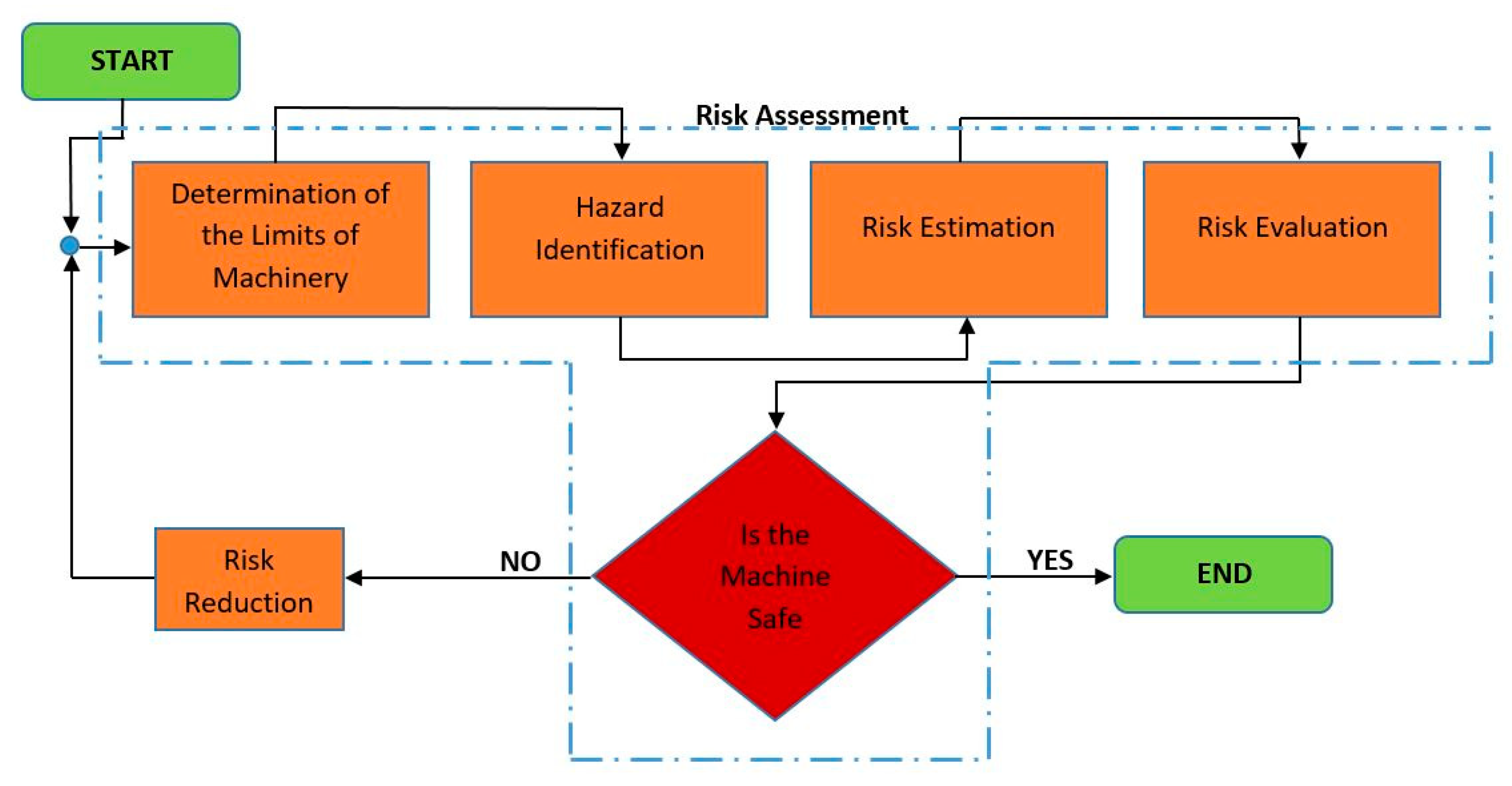
Figure 2 provides a simplified flow chart of the risk management analysis as proposed by ISO 12100:2010. The analysis is divided in five major steps: determination of the limits of the machinery, hazard identification, risk estimation, risk evaluation, and risk reduction. Each step is further analyzed within the paper.
Determination of the limits of the machinery is the first step of the risk management analysis, and it defines the running conditions of the robotic structure in terms of use, space, and time.
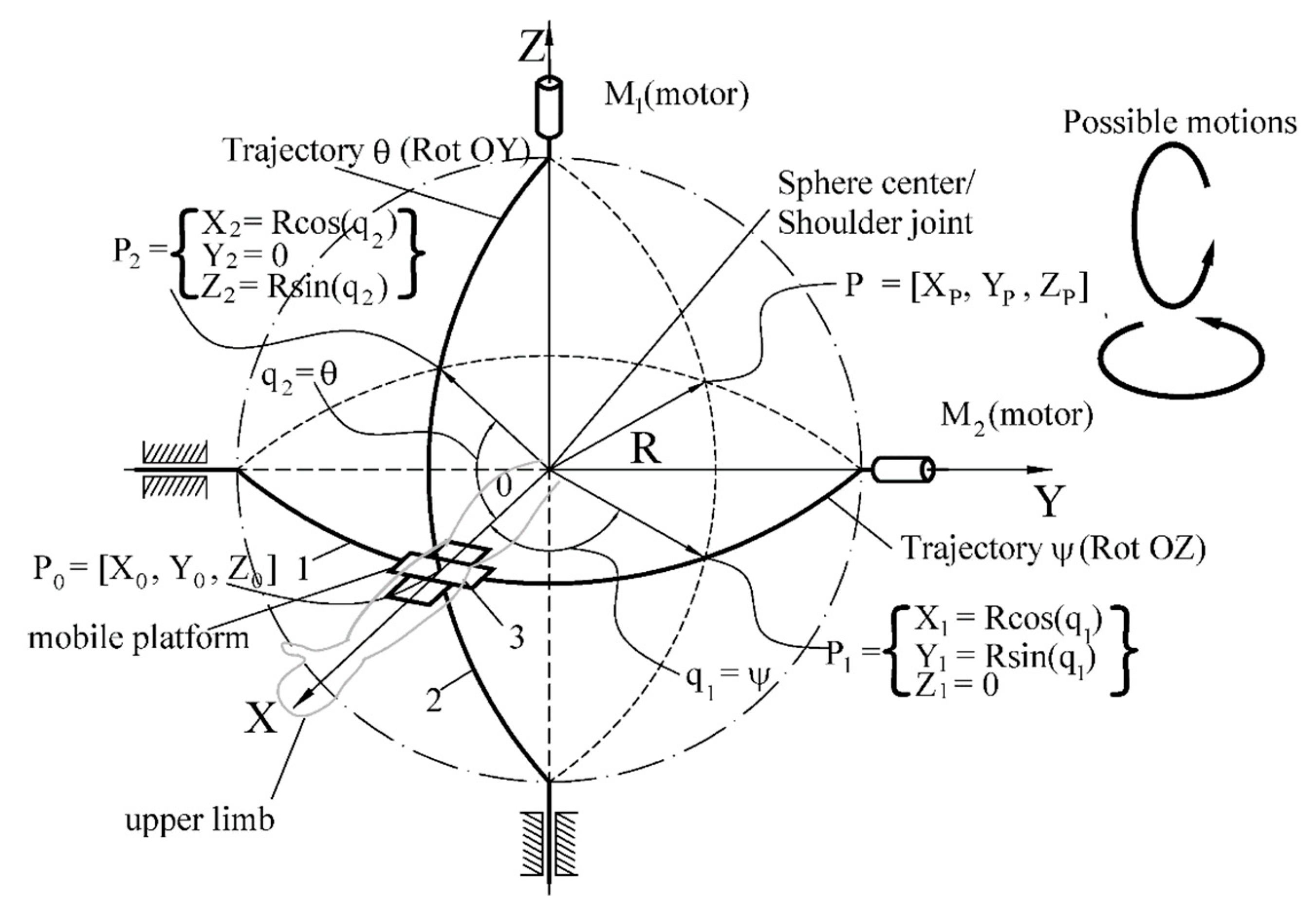
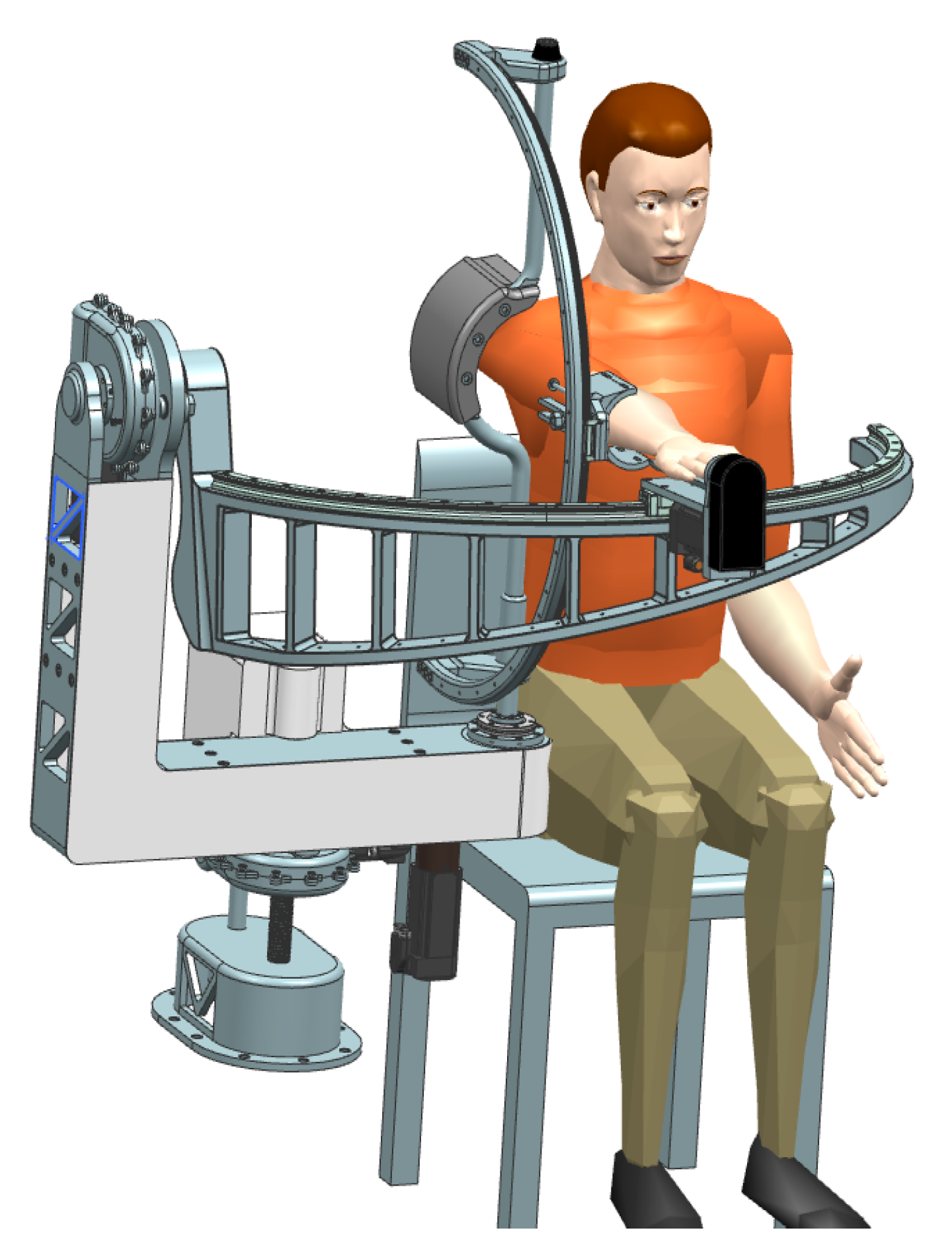
First, the relative position between the patient and the robotic structure is defined. During the rehabilitation procedure the patient is seated with the impaired arm attached to the robotic structure, which must perform motions that would replicate specific exercises defined by medical experts.
Normal running condition of the robotic system implies that the patient is seated with the arm attached on to the rehabilitation mechanism, and the patient, due to his impairment, cannot create any other resistance in the mechanism other than the one created by its own arm. Special attention should be paid when the patient regains some of the lost dexterity and some of the forces within the mechanism are reduced or amplified (depending on the degree of recovery, the patient can help the robotic structure in the rehabilitation process or he can create extra resistive moments into the mechanism by opposing the rehabilitation motion). A detailed analysis of the interaction modalities between the robot and the patient is illustrated in Thompson and Perry [30].
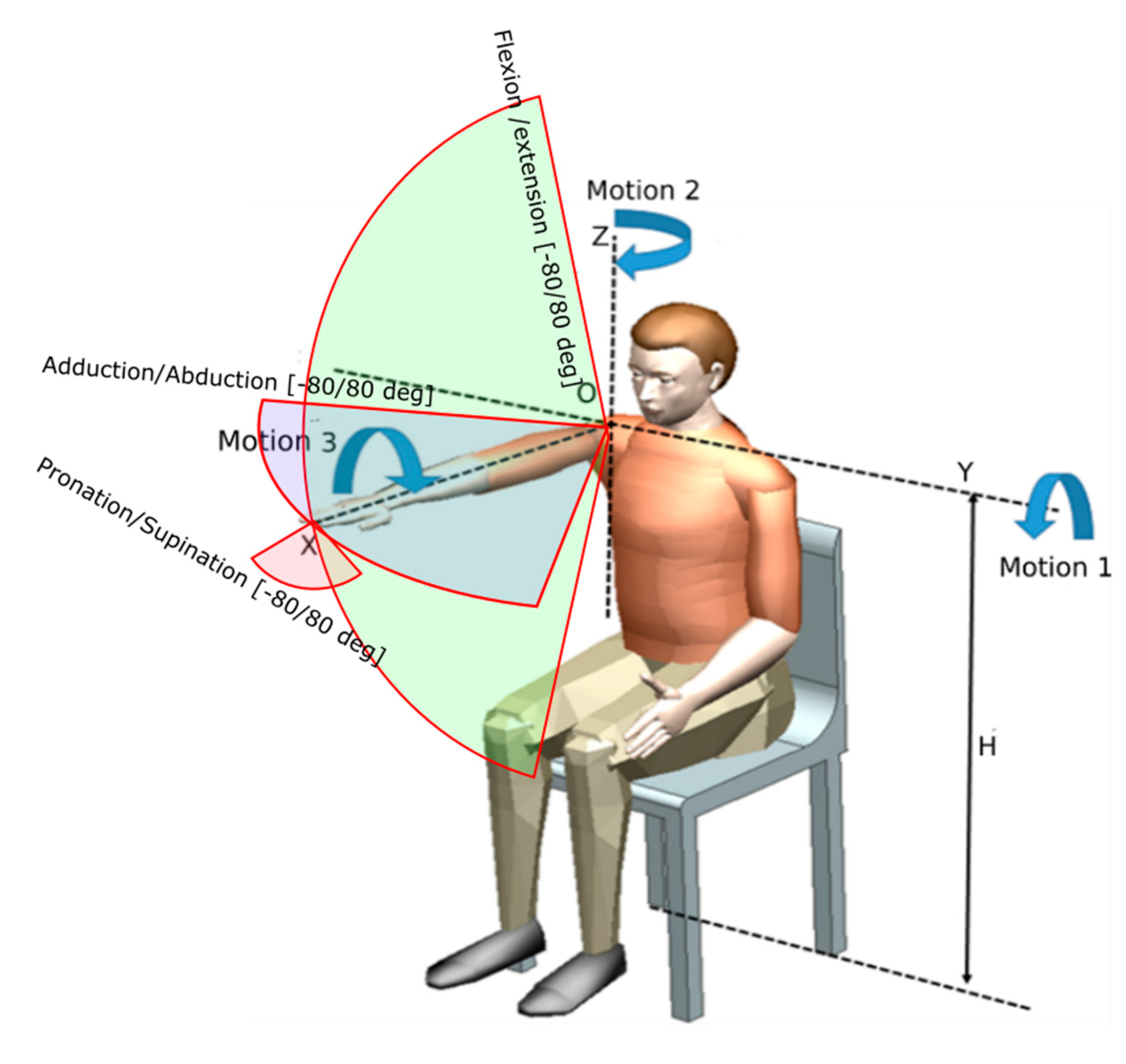
The rehabilitation motions targeted by ASPIRE are also identified using Figure 3, where
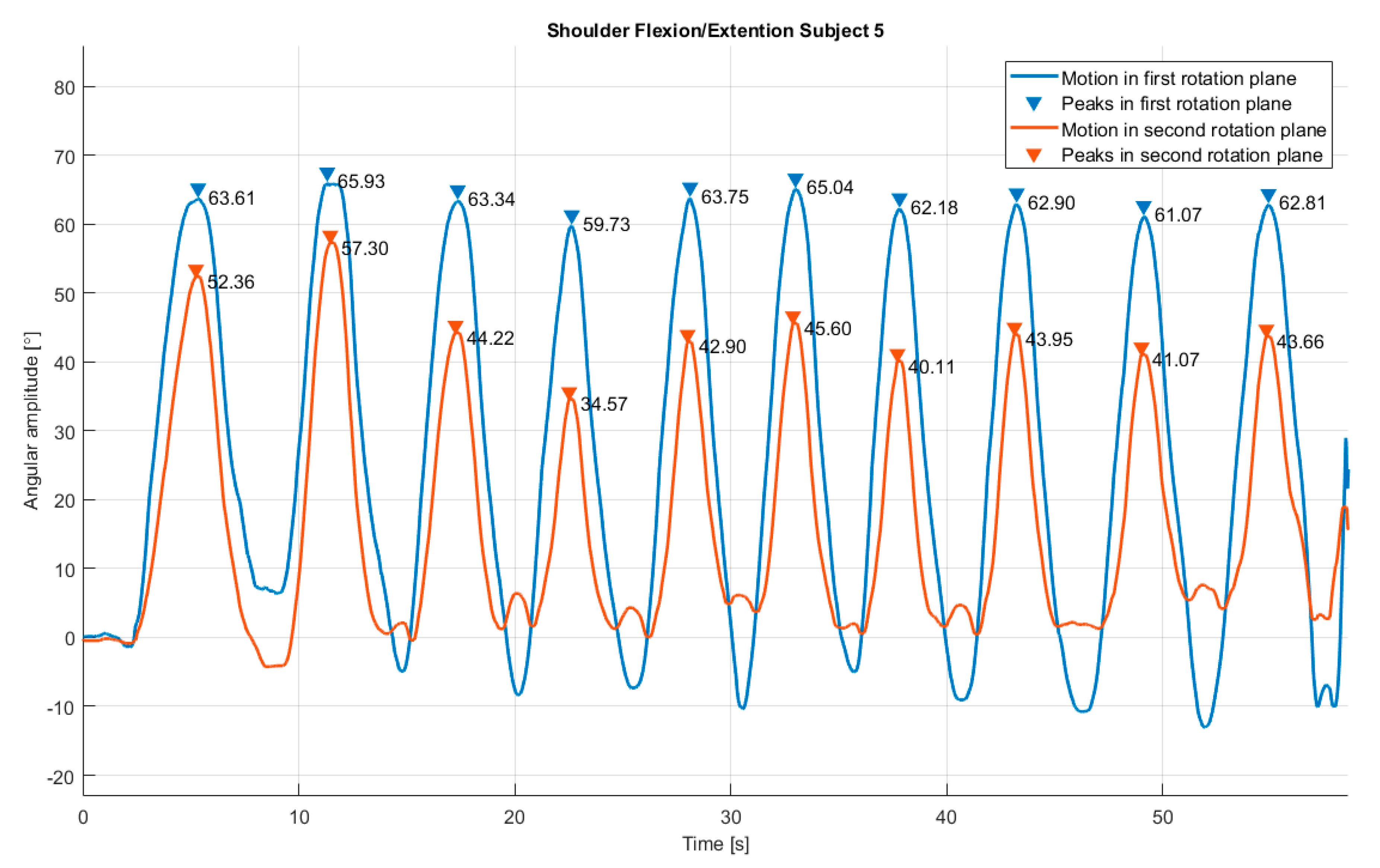
  • Motion 1—flexion /extension of the shoulder performed around OY axis with a maximum range of ±80;
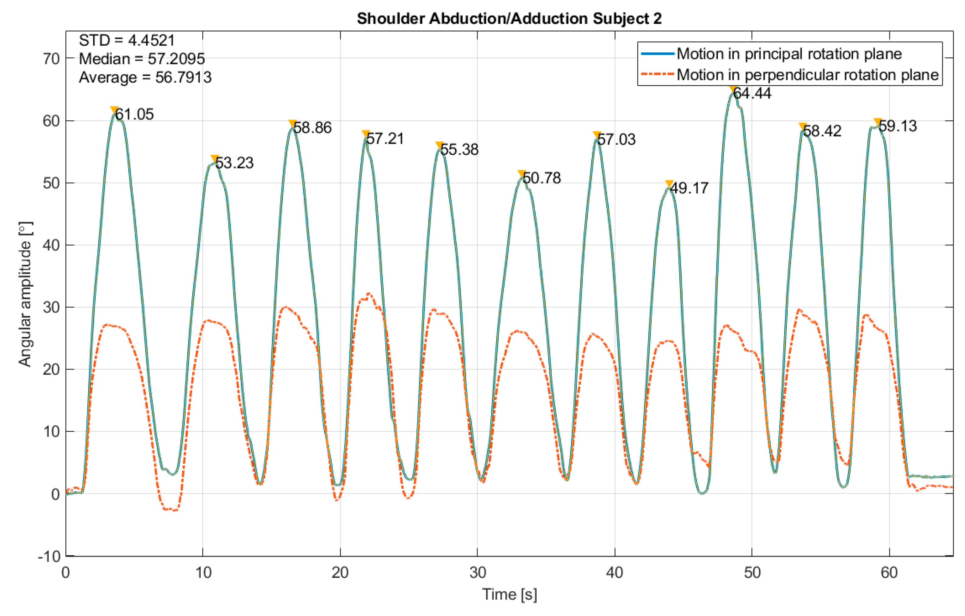
  • Motion 2—adduction/abduction of the shoulder performed around OZ axis with a maximum range of ±80;
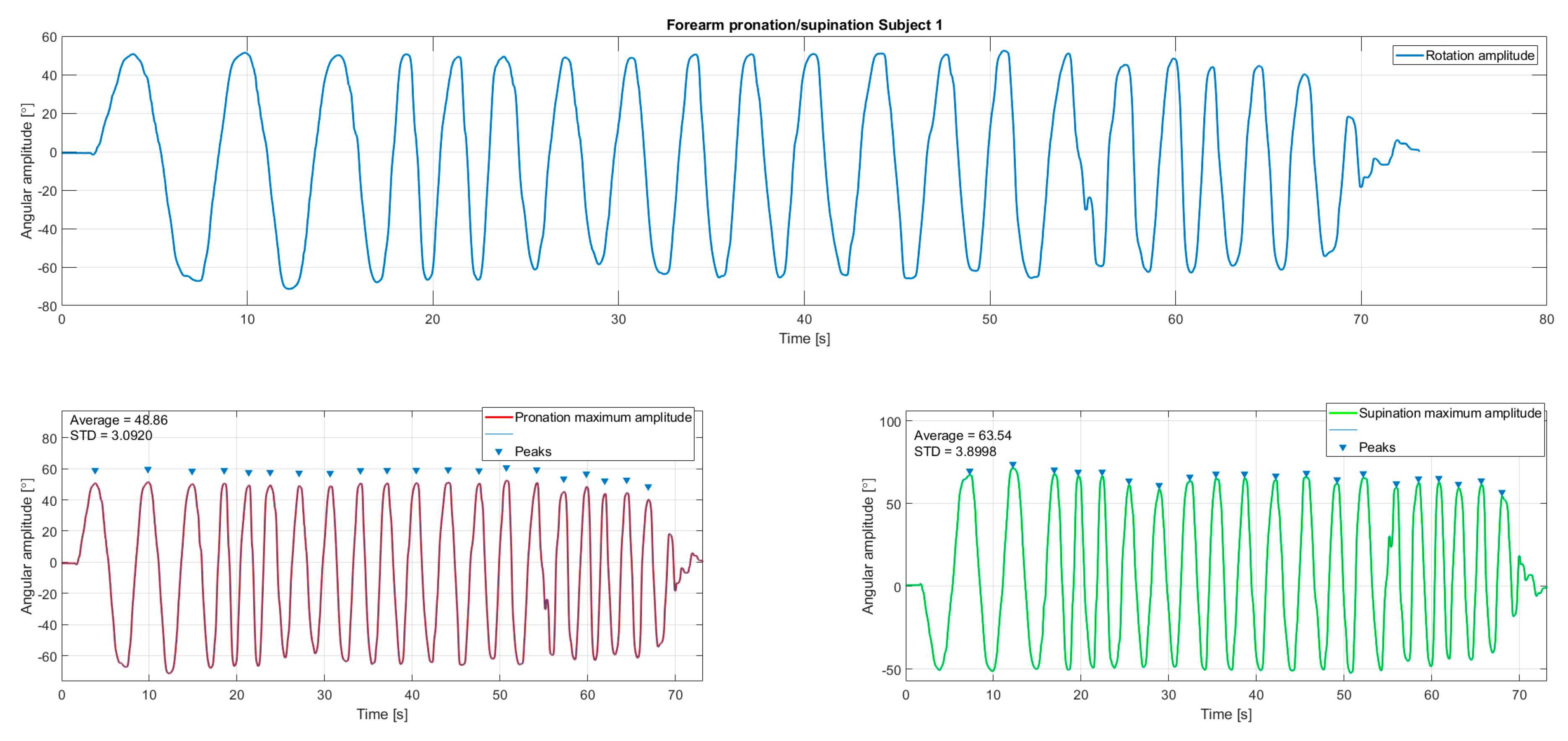
  • Motion 3—pronation/supination of the forearm performed around OX axis with a maximum range of ±80.
The total space volume occupied by the robotic structure should not exceed the height of the patient when seated and the reach of his arm during the rehabilitation process.
The robotic structure should be reliable enough to ensure the repetitive motion of the impaired limb of several patients in clinical or home conditions.
The robotic structure should have a fixed base, independent of the patient reference system to ensure the stability during the rehabilitation process.
The patient can be moved and seated during the rehabilitation procedure using a wheel chair.
Based on calculated anthropomorphic data, the robot should have adjustable elements that would fit with different patient sizes without any influence upon the actual limb motion.
Hazard identification is a crucial step in risk assessment process, because within this stage all the dangerous situations than can occur have to be identified. If a hazard is not taken into consideration it will be also missed in this step in the risk reduction phase.
There are various types of hazards: mechanical, electrical, thermal, noise, vibration, radiation, material, ergonomic, running environment, or a combination of all the above. The identified hazards are presented in the following lines.
Mechanical hazards:
  • MH1: Arm crushing caused by wrong motion of the spherical mechanism (this hazard can be created by the therapist by introduction wrong parameters not correlated with the patient anthropomorphic characteristics, by wrongly inserting the patient within the rehabilitation system, or it can even be a consequence of a power supply failure).
  • MH2: Cuts/scratches caused by edges of metal parts (this hazard can be created by improperly design or manufacturing of the mechanical parts of the robotic system).
  • MH3: Body parts crushing by moving parts of the robotic structure (this hazard can be created by the therapist by introduction wrong parameters not correlated with the patient anthropomorphic characteristics or by wrongly inserting the patient within the rehabilitation system).
  • MH4: Over limit motion caused by mechanical end-stroke parts malfunction.
  • MH5: Impact between the robotic structure and patient.
Electrical hazards:
  • EH1: Risk of electrocution of the patient.
  • EH2: Risks of harming the patient by sensor system malfunction.
  • EH3: Over limit motion caused by end-stroke sensor malfunction.
  • EH4: Risk of short-circuit.
  • EH5: Risk of overload.
Thermal hazards:
  • TH1: Burns caused by overheating parts of the robotic structure.
Noise hazards:
  • NH1: Acoustic discomfort caused by close-to-the-ear functioning mechanisms.
Vibration hazards:
  • VH1: Patient harm by loose parts of the mechanisms.
  • VH2: Patient harm by uncontrolled vibration of the mechanism caused by malfunctions.
Ergonomic hazards:
  • ERH1: Risk of falling—the patient is in a wheel chair that can flip during the rehabilitation procedure.
Risk estimation was carried out in order to find out the severity of each risk. Several methods as risk matrix, risk graph, or numerical scoring are used to estimate the risk. All risks are estimated depending on their severity and probability of occurrence.
The severity of a risk can be numerically estimated as
  • Catastrophic: 100;
  • Serious: 90–99;
  • Moderate: 30–89;
  • Minor: 0–29.
The probability score can be numerically estimated as
  • Very likely: 100;
  • Likely: 70–99;
  • Unlikely: 30–69;
  • Remote: 0–29.
The final scoring of each hazard is computed by adding the two values from severity and probability.
In order to estimate the above identified hazards regarding the ASPIRE system 10 design engineers with a background in medical applications were interviewed and asked to fulfill the questionnaire provided in Appendix A, using Table A1 to record the severity and Table A2 to record the probability of the hazard; their scores are displayed in Table 1 and Table 2.
In Table 3 the mean values of recorded data are displayed and the overall score is computed by adding the severity score and the probability score.
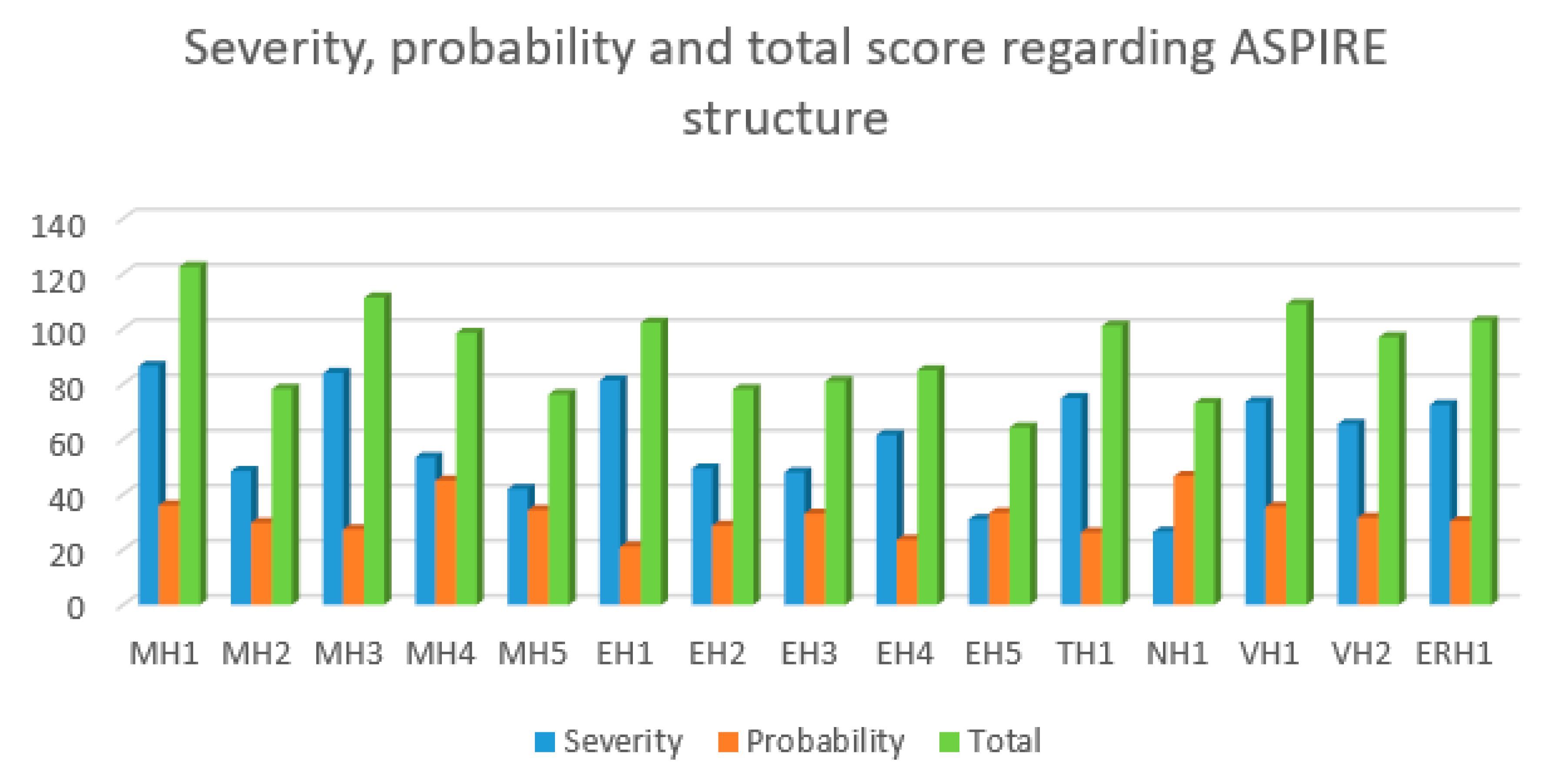
Below, the scores of each identified hazard are graphically represented using bar charts.
The most severe hazard (Figure 4, blue bar) was identified to be MH1 (arm crushing caused by wrong motion of the spherical mechanism), the highest probability was scored by NH1 (acoustic discomfort caused by close-to-the-ear functioning mechanisms (Figure 4, orange bar) and the highest overall scorer was MH1 (Figure 4, green bar).
The risk evaluation process consists of deciding whether a hazard requires risk reduction and to determine whether reduction process has created new hazards or increased the existent risks.
The overall scoring of each identified hazard will be compared with the following evaluation scale:
  • High: over 151;
  • Medium: 101–150:
  • Low 61–100;
  • Negligible: 0–50.
The risk evaluation is carried on in Table 4.
The identified hazards that need reduction have to score a medium or high score. A total of six identified hazards (MH1, MH3, EH1, TH1, VH1, and ERH1) scored a medium value the rest of the hazard scoring low values. During the constructive design phase of the ASPIRE system all the identified hazards shall be taken into account, but special care should be paid regarding MH1, MH3, EH1, TH1, VH1, and ERH1.
When developing the risk reduction methods each previously identified hazard was individually analyzed, the outcome of the analysis being presented in Table 5.

2.3. Failure Mode and Effects Analysis of ASPIRE Robotic System

Another method to identify, reduce, and eliminate risks within a system is Failure Modes and Effects Analysis (FMEA). FMEA is a systematic method for failure analysis developed by reliability engineers [32], and it implies analyzing as many as possible elements of a system to identify possible failures and the causes and effects of these failures.
The FMEA process for the ASPIRE robotic structure is displayed in 
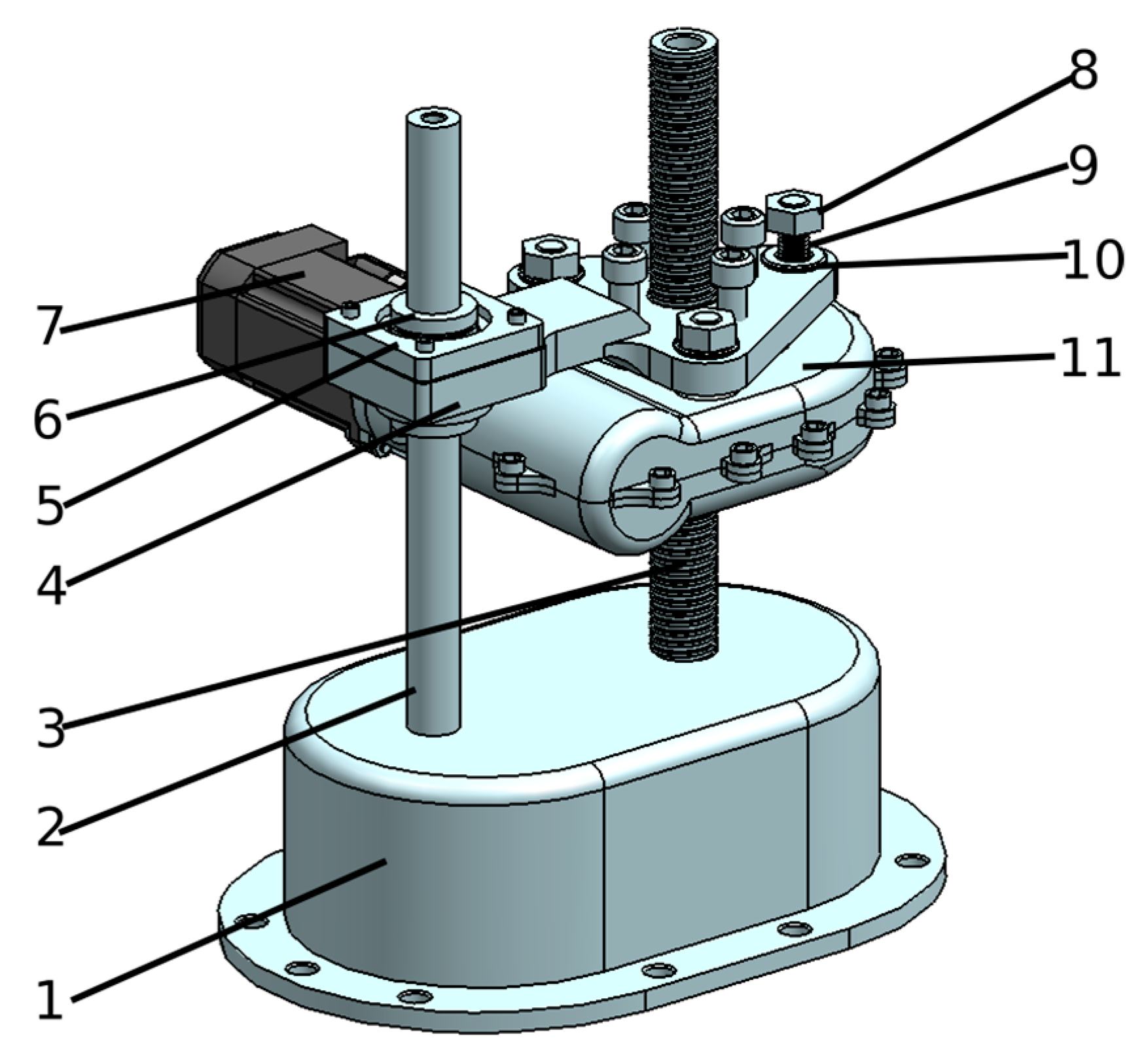
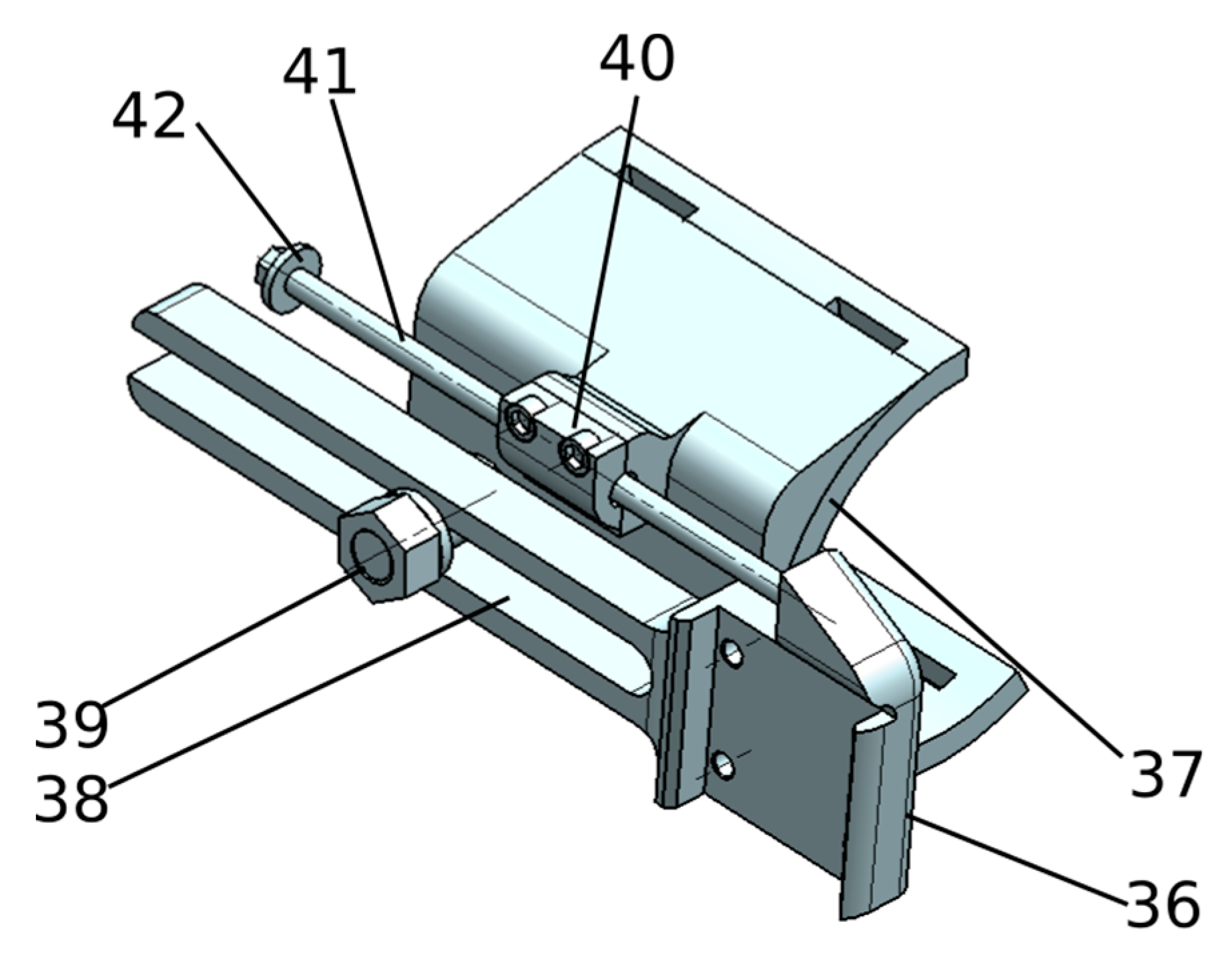
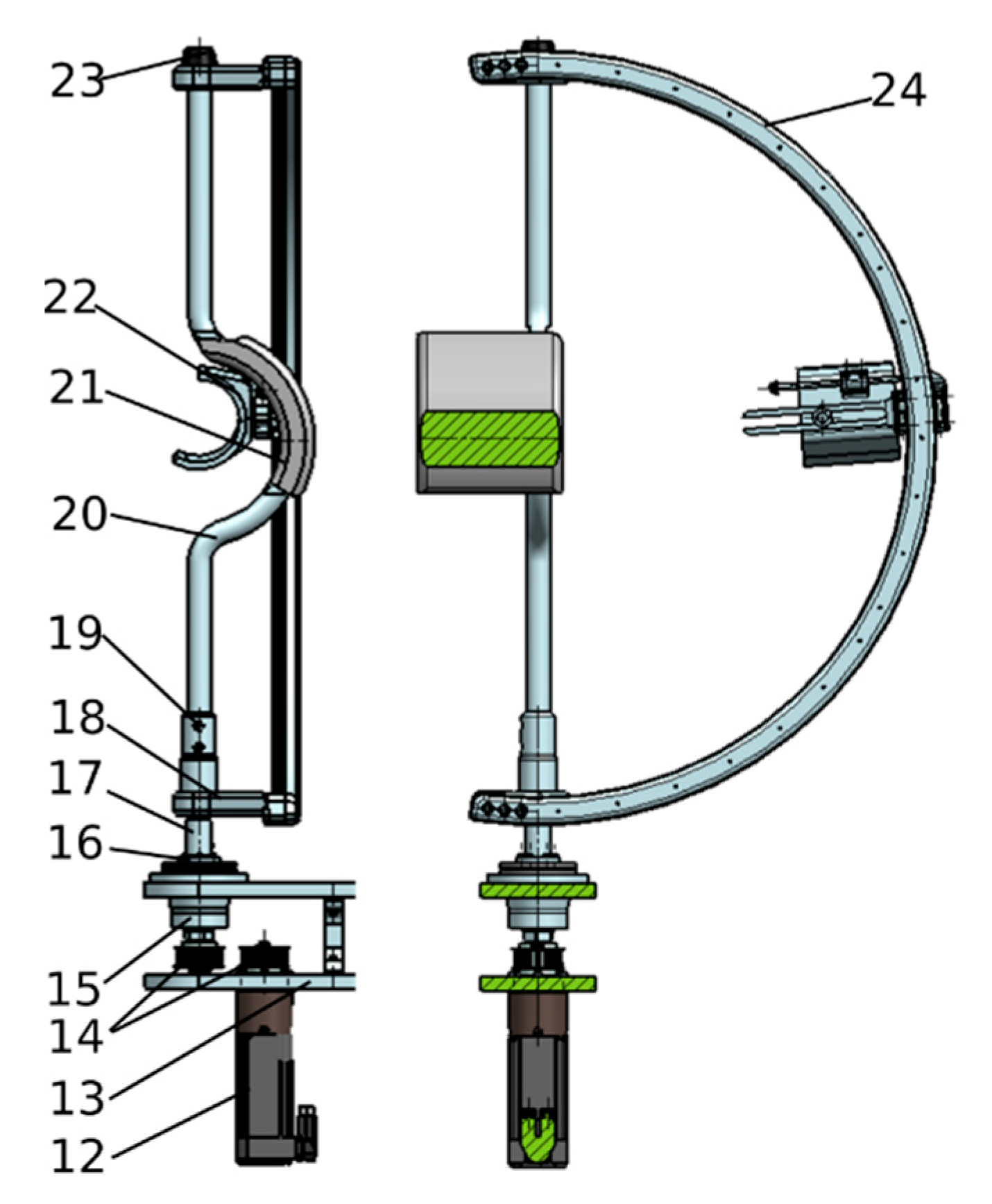
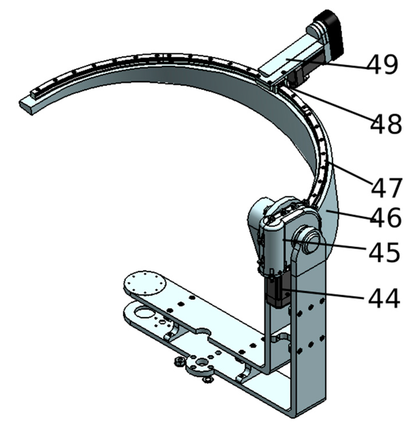
Table 6. To provide a reliable solution for the rehabilitation system all the above failure modes have to be analyzed and embedded in the robotic system during the design stage. To overcome F1, F2, F3, and F4 failure modes, physical end-range limiters should be embedded in the constructive design of the robot to stop the mechanism when the maximum stroke is reached. To prevent F1 and F2 simple screw nut assembly buffers have to be mounted on both circular slides. To prevent F3 and F4, adjustable buffers may be used to modify the stroke of each mechanism based on the patient body type (height, weight, etc.). Each stroke limit should have a double check-up, once by proximity sensors mounted to detect a possible collision, and second by the control system that gives the possibility to impose discreet limits of kinematic axis, making the buffer mechanism to be a supplementary solution in case of F1, F2, F3, or F4 malfunctions.
To overcome F5 and F6 a worm gear is a possible solution. The height adjustment mechanism may be actuated by a servomotor attached to a worm gear reduction box, mechanism that slides along a screw nut assembly. For this mechanism, buffers have to be mounted to avoid end-range collision between the robot’s links (or patient). Proximity sensors are the primary safety system along with the discrete limit of the kinematic axis. To prevent F6 a worm gear reduction could also be used, this time to overcome the possible forces that can occur in the mechanism during the rehabilitation process.
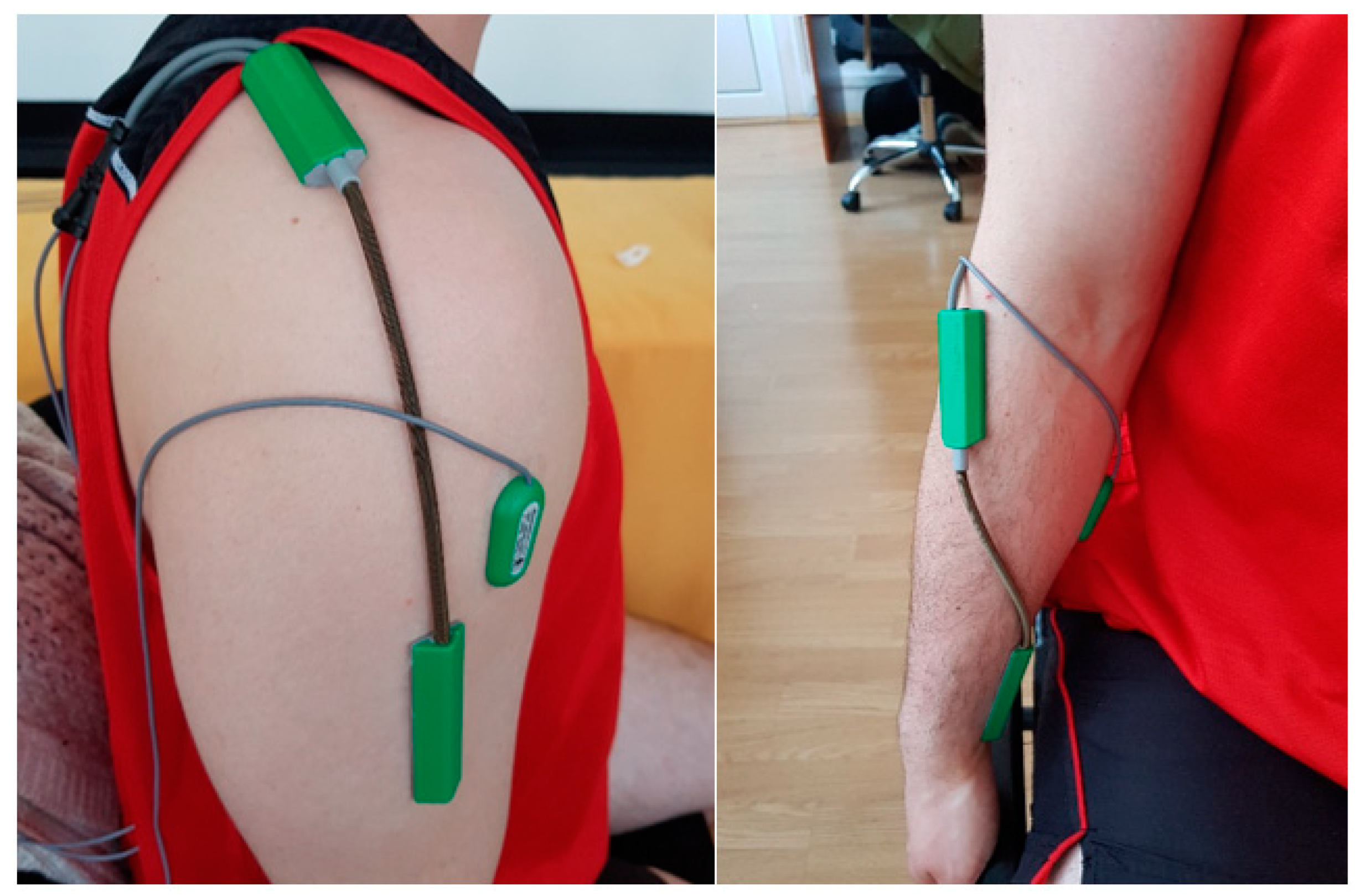
To overcome F7, F8, and F9 an external sensor system may be embedded in the rehabilitation system. Failure F7 can occur when the encoder of the motor is not functioning properly, for this a double check sensor system could be implemented. This sensor system consists of mounting and monitoring goniometers placed on the impaired limb of the patient. Before performing the rehabilitation procedure, the patient is measured by a kinetotherapist and a rehabilitation chart is defined with the maximum range of the patient articulations. Based on these measurements the setup of the robotic structure is defined (end-range buffers and inductive sensors are set to detect the maximum range of each rehabilitated articulation); using the goniometers the joint angular displacement is measured, preventing the system to go over the reachable limit of the patient and in the same time giving the possibility to monitor, register and compare the progress of the patient. To prevent failure F8 a special subprogram could be implemented into the control system to monitor and prevent processor failure.
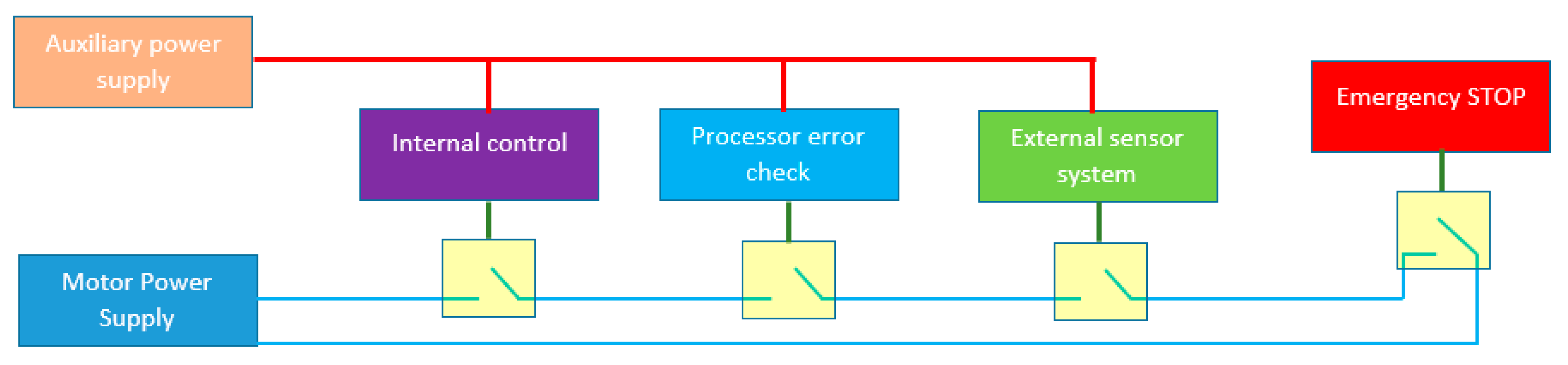
Figure 5 represents a safety loop in the ASPIRE’s controller. The robotic system can be forced to a sudden stop through either one of the following four systems.
  • ES1: Emergency stop system, manually actuated by the supervising personnel or by the patient (if possible) and gives the possibility to stop the rehabilitation procedure at any time if the supervisor observes some incorrect functioning of the system; following an emergency stop the system has to be reinitialized after the errors in functioning have been identified and eliminated. Correlated with the emergency stop a special procedure to detach the patient from the robotic system should be implemented.
  • ES2: External sensor system represents the goniometers system mounted on the patient’s arm, monitored by a special, individual processor that communicates with the main controller of the robotic system; any abnormal values or the lack of communication will induce an emergency stop of the system.
  • ES3: Processor error check system is the subroutine implemented to monitor the errors that can be created by the faulty functioning of the processor.
  • ES4: Internal control system is the main control module of the robot that can stop the system if some uncontrolled forces are identified, or if the mathematical model of the structure identifies some unreachable zones embedded in the rehabilitation chart.
All these safety systems are able to individually stop the procedure at any time without any confirmation; the safety and health of the patient at risk can be seen in Table 4.

2.4. Technical Characteristics Analysis and Prioritization

In order to evaluate the relative importance the technical characteristics of the robotic structure an Analytic Hierarchy Process (AHP) is used. For this, a number of technical characteristics that the robotic structure needs to fulfill are defined in Table 7. Further, all of the defined technical characteristics are compared between each other using software that provides an intuitive graphical representation of the AHP process. The comparison process is represented in Figure 6. The results of AHP are shown in Figure 7 where top three scores were TC4, TC3, and TC5 all related to the safety of the patient during the rehabilitation procedure.

3. Results

The above proposed solution was used to obtain the safe characteristics of the ASPIRE robotic system used in the upper limb rehabilitation of the post-stroke survivors. Following the flowchart provided in Figure 8, after the task of the robotic structure was identified, the technical requirements resulted and the initial concept of the structure was conceived. Starting from the concept of the system and from the requirements, using a risk assessment process, a FMEA and an AHP, hazards, failures modes, and the importance of each identified technical characteristic, two main safety components were identified. First safety component is provided in terms of control of the robotic structure while the other one consists of safety related mechanical components.
The safety related mechanical components are presented in the following lines as part of the constructive design of the robotic structure followed by a numerical–graphical simulation of the obtained configuration in order to validate the mathematical model and the kinematic aspect of the structure both important parts for the safety in control during the functioning of the robotic system. For the control related safety features a set of experimental data is provided in order to validate the external sensor system of the robot in Section 3.3.

3.1. The Constructive Design of ASPIRE

As a result of the above analysis, the ASPIRE robotic structure has been designed to fulfill all the technical characteristics defined in Section 2.3 and, at the same time, reduce most of the risks and hazards previously identified.
A series of fine tunes were implemented into the robot design to address the difference in anthropomorphic parameters of each patient:
  • Height adjustment (Figure 9)—adjusts the height of the arm–robot attaching device with a total stroke of 200 mm (from 800 mm to 1000 mm ).
  • Forearm adjustment (Figure 10)—adjusts the forearm attaching position.
Figure 9 presents the height adjustment mechanism composed of (1) the base of the robotic structure, (2) a Ø25 fix calibrated rod, (3) a M32x5 ball screw, (4) an attaching plate, (5) a bearing case, (6) axial bearing, (7) a servomotor, (8) an M14 nut, (9) an M14 threaded pin, (10) a Ø15 washer, and (11) a worm gear reduction box (all sizes expressed in mm).
Figure 10 presents the forearm adjustment device, attached to the vertical circular guide using the link (36) and 4 x M4 screws; component (37) is the forearm place holder and was designed using soft material (3D printed) as it is one of the first parts from the mechanism to yield in case of malfunction, avoiding harm the patient. The patients forearm is tighten in place using an elastic harness. Link (40) contains a sliding bearing that moves along the sliding rod until the limiter.
The robotic structure, divided into three mechanisms (each targeting a specific motion for the upper limb rehabilitation), is presented in Figure 11, Figure 12 and Figure 13. The mechanism for the adduction /abduction rehabilitation motion (Figure 11) consists of (12) a servomotor, (13) a rigid frame attached to the height adjustment device, power transmission from the servomotor to the rehabilitation mechanism’s central axis (20) is made using timing belt (14), the backlash of the transmission is reduced using pair of bearings system (15) & (16), (17) is a spindle-bore gearing, the central axis of the mechanism is composed of links (18) & (19) rigidly attached using threaded pins; link (21) is a special designed element to contribute to the safety characteristic of the structure; this component is manufactured from a soft material to yield in case of malfunction of the robotic structure and to avoid damage of the shoulder of the patient. Element (22) is the forearm adjustment mechanism presented above. Element (23) is a threaded bolt that tightens all the assembly together, and (25) is the vertical circular guide of the mechanism. The mechanism for rehabilitation for the flexion/extension motion of the shoulder is displayed in Figure 12. The mechanism is actuated using the servomotor (44) attached to the worm gear reduction box (45), (46) is the horizontal circular guide of the mechanism on which is attached the slider of the mechanism (48), and the pronation/supination mechanism (49) of the structure. Figure 13 presents the mechanism for pronation and supination rehabilitation of the forearm; the palm of the patient is attached (using a harness) on the palm support (61). The mechanism is actuated using the servomotor (58) and a timing belt (59). The palm support is attached to the frame (62) using a radial-axial bearing system. The element (63) is a plastic cap that covers the moving parts of the mechanism.
The horizontal circular guide of the flexion/extension rehabilitation mechanisms (46) is a curved beam of equal strength, designed to uniformly distribute the forces in the mechanism and, at the same time, to allow easy access of the patient limb into the rehabilitation robot. A finite element analysis (FEA) was performed using Siemens NX for this element to determine the maximum deformation and the distribution of deformation during the rehabilitation process. For this a 175 N force was applied in different points of the element and a maximum deformation of 0.0047 mm resulted; a deformation that does not influence either the functioning of the robotic structure or the safety of the patient. The 175 N force was obtained applying a 2.5 safety coefficient to the force of 68.4 N statistically determined in [33] based on medically validated anthropomorphic data; the FEA analysis is displayed in Figure 14 while the final solution of the ASPIRE robotic structure is presented in Figure 15.
Some extra safety features were included in the design of the grip areas for the forearm, shoulder, and wrist (Figure 16). All these components are made of a low resilience material (3D printed ABS), and the fasteners of these components are also made of low resilience fabric material. In case of unusual forces in the robotic system, these components will be the first to break without risking harm to the patient.

3.2. Motion Simulation of the Robotic Structure ASPIRE

After the constructive design of the robotic structure ASPIRE has been finalized, some motion simulations were conducted. ASPIRE has the particularity that the point U defined in Section 2 of this paper is constrained to move on a sphere.
The simulation was obtained by varying both orientation angles of the mechanism, miming a shoulder rehabilitation procedure, using data provided in Table 2.
The angular speed and acceleration at the level of the upper limb are
ω = 10 / s ; ε = 5 / s 2
The following relations are defined in order to compute the angle and the arc length on the sphere.
{ D X = cos ( θ f ) cos ( ψ f ) cos ( θ i ) cos ( ψ i ) D Y = cos ( θ f ) sin ( ψ f ) cos ( θ i ) sin ( ψ i ) D Z = sin ( θ f ) sin ( θ 0 )
The angle on the sphere and the length of the angle is computed using Equation (5):
{ α = 2 asin ( D X 2 + D Y 2 + D Z 2 2 ) l α = R × α
To compute the time of the motion, the previously defined angle is used, and the maxim speeds and accelerations are imposed (using a trapezoidal profile for the speed). The computed motion times are
  • t1—the acceleration time;
  • t2—the motion before starting decelerating;
  • t3—full motion time.
The expression for each time is given in Equation (6).
t 1 = ω ε ; t 2 = | α | ω ; t 3 = | α | ω + ω ε
Finally, the individual angular acceleration for each angle is computed using Equation (7).
ε ψ = ψ f ψ i 2 t 1 t 3 t 1 2 ( t 3 t 2 ) 2 ; ε θ = θ f θ i 2 t 1 t 3 t 1 2 ( t 3 t 2 ) 2
Using a sequence of angular values (Table 8) to simulate a complex trajectory the rehabilitation motion is presented. In order to validate the constructive design of the robotic structure, the trajectory has been simulated using two different environments. First, the trajectory was mathematically determined and computed using the kinematic model of the robot implemented in MATLAB [34], where the coordinates from Table 8 were used as input data and the result of the simulated trajectory is illustrated in Figure 17a. In Figure 17b, the same trajectory was obtained by varying the orientation angles using the same trajectory in the modeling software Siemens NX [35]. Both simulations had the same input data, but in MATLAB the trajectory was obtained using the inverse kinematic model of the structure while Siemens NX generated the same trajectory using the virtual model of the structure. By simulating medically relevant rehabilitation trajectories and in the same time validating the mechanical structure of the robotic structure, some of the previously identified mechanical hazards are reduced through a robust control of the motion during the procedure and in the same time by knowing the coordinate of every moving part of the mechanism during the rehabilitation procedure.
During the simulation, computed data were recorded and used to evaluate the correspondence between the two simulation environments. In Figure 18 these data are plotted using MATLAB. In the upper part of the plot, the active coordinates (q1 & q2) computed using MATLAB are displayed according to position (green color), speed (light blue), and acceleration (yellow). Using dashed line, the same coordinates, but extracted form Siemens NX, are plotted and overlapped.
In the second section of Figure 18 the displacement of X (green color), Y (light blue color), and Z (yellow color) coordinates computed in MATLAB is expressed. The displacement extracted from Siemen NX is plotted using a black dashed line.
By analyzing the above graphs, it can be seen that no significant differences are between simulated trajectories using different environments; this leads to the validation of the mathematical model of the robotic structure and it allows further implementation into the control system of the robotic structure.

3.3. Minimizing the Risk for Patient Injury Using an External Set of Motion Sensors

With reference to MH1, MH3, MH4, MH5, and EH3, there exists a common cause that can trigger an event with negative consequences for the patient: the attachment of the patient arm to the robot structure. As each patient has unique anthropometric characteristics and taking into account that the arm cannot be constrained too stiff there is always a risk of relative motion between the patient arm and the robotic structure. This relative motion introduces a difference between the values programmed in the robot (which are set by the physician) and the motion amplitudes of the patient arm (which are targeted by the physician). Additionally, during the exercises, as the muscles relax or the patient changes his/her position there might be a variation of the arm position with respect to the robot. Thus it must be mentioned that there is a common risk with high probability to have a difference between the robot and the patient arm motion amplitudes which imposes an adequate independent estimation of both values. The robot system uses encoders and proximity sensors on all joints but these cannot measure directly the actual motion of the patient arm where a direct measurement has to be used. This can be achieved properly by using biosensors that measure the motion amplitudes which are attached directly to the patient arm. Such sensors should enable the following.
Initial patient assessment with respect to the current motion capabilities at the level of the affected limb;
  • Continuous measurement of the joint amplitudes;
  • Real-time data processing and event triggering;
  • Data recording;
  • Simple integration in a medical device based on specific certifications.
  • The authors propose the integration of a solution from Biometrics [36] an acquisition system able to collect both analog and digital data using a wide range of sensors, available in portable configurations, equipped with a precision interface and state of the art surface EMG. The system is designed readily interface to most video based motion capture system and a series of other data acquisition interfaces, allowing the EMG and goniometry data to be synchronized and collected in the same time.
For the study of the upper limb motions, the Biometrics sensor system consists of
  • A goniometer with two axes (that can measure the motion amplitudes in two perpendicular planes) that will be used on the shoulder (Figure 3, Motions 1 and 2);
  • A torsiometer with one axis used on the forearm (Figure 3, Motion3);
  • Several EMG sensors that assess the muscle activity;
  • A real-time signal processing device with Bluetooth connectivity.
This sensor system was chosen because all the equipment that will be integrated in the direct measurement system is CE certified as medical devices in conformity with the European directive 93/42/EEC; because from a safety point of view one needs to have an accurate direct measurement system of both motion amplitudes and their variation in time and because the way that the data is processed and transmitted allows real time patient monitoring and the possibility to record the patient evolution over long periods of time.
The authors performed a set of experimental tests with the proposed equipment aiming to assess the following.
  • The attachment of sensors on different subjects;
  • The motion amplitudes dispersion for multiple repetitions;
  • The variation of the joint amplitudes for secondary motions;
  • The behavior of the joints at maximum motion ranges.
The measurements were performed on five healthy subjects reproducing each of the motions of the ASPIRE robot. The components of the system are illustrated in Figure 19 and the positioning of the sensors on the upper limb of each subject is presented in Figure 20.
Each subject was requested to perform individually the following motions in correlation with the ones defined in Figure 3:
  • Motion 1: adduction/abduction of the shoulder (ten repetitions);
  • Motion 2: flexion/extension of the shoulder (ten repetitions);
  • Motion 3: pronation/supination of the forearm (ten repetitions).
All the data was recorded and processed in MATLAB using specific signal processing tools. The experimental values are presented in the Table 9.
Analyzing the data, some general and motion-specific conclusions can be drawn. All the subjects used for the testing were healthy and they were told to perform the motion in the way it felt the most comfortable for all. Subject 1 is female and has higher values than the other subjects supporting the generally accepted idea that women have better joint movements than men. Looking at the two motions at the level of the shoulder, the abduction/adduction motion is executed in a nearly horizontal plane (see Figure 21) this position being comfortable for all the subjects, which is not the case for the flexion/extension, where all subjects preferred to move the hand vertically in a plane between the sagittal and coronal ones. This is why a variation of the angular motion is registered for both measurement axes of the goniometer (Figure 22). The level of the forearm showed big differences between the motion amplitudes, but with more constant amplitude, which is shown by the lower values in the standard deviation. A graphical representation of the data recorded for the forearm motion is illustrated in Figure 23.
With respect to the risk minimization, the integration of an external system of sensors mounted directly on the patient targeted limb brings multiple benefits:
  • The initial assessment of the motion amplitudes of each joint can be studied using these sensors mounted on the patient;
  • During exercises, the real-time monitoring of the joint movements will prevent any injury that could be caused by relative displacements between the robot and the patient that would make the internal system of sensors mounted on the robot to provide inaccurate data;
  • The slippage of the upper limb from the robot fixtures will represent a sudden large variation of the body mounted sensors that will trigger an immediate stop of the robot;
  • The recorded data enables the monitoring of patient progress over time;
  • The experimental data have shown that even the simple motions should not be performed in the specific body planes as other positions are more comfortable for the patient.

4. Discussion

Most existing regulations do not clearly specify safety standards in achieving safety behavior in medical rehabilitation, thus a series of adjacent regulations are used to provide a reliable solution for the robotic system. In order to provide this solution, different experts from various technical fields (mechanical, electric, medical, etc.) need to team up to provide a competitive solution.
This research uses a sample of ten researchers from the same engineering fields, to identify a series of hazards that can occur during the medical rehabilitation of the upper limb using a robotic system. Following the identification of the hazards, each researcher was asked to provide a numerical evaluation in terms of severity and probability of each hazard using a numerical evaluation scale delivered within a questionnaire.
The obtained scores were analyzed and the hazards that needed reduction were identified using previously defined numerical scale. Following this risk identification a secondary approach was used as FMEA table to identify the possible failure modes of the system. The technical characteristics of the robotic system were also identified using the same sample of researchers.
The result of risk assessment, FMEA and AHP were all part of the constructive design of the robotic structure and in the same time the control system of the medical rehabilitation solution was configured in terms of safety aspects.
Using a numerical and a graphical simulation the mathematical model of the robotic structure was validated.
Finally, the external sensor system was validated using a 5-person sample to measure the motion amplitudes during the rehabilitation motion of the shoulder.
The results of this approach could easily be influenced by the number of the processed questionnaires regarding the severity and the probability of hazards, and in the same time the accuracy of the external system may be also influenced and improved by the sample size of experimental subjects.
Before performing the rehabilitation procedure the patient will undergo an initial assessment followed by the definition of a personalized set of exercises. All these exercises and the resulting progress will be monitored using the same Biometrics sensor system. In case the process is inconsistent the doctors will adjust the rehabilitation exercises accordingly aiming to maximize the results of the therapy while ensuring the necessary level of safety for the procedure.
The analyzed robotic system momentary cannot perform task-based rehabilitation and it cannot teach the patient to perform writing, eating, grasping, or other task-related motions, the entire system being developed in order to recreate the neuronal paths of shoulder motion. Future work may consist in analyzing the entire task-based motion of a day by day activity and divide it into limb articulation relative motions that can furthermore be implemented in the rehabilitation process of the shoulder.

5. Conclusions

Medical rehabilitation using robotic devices is slowly becoming a necessity due to the demographic changes creating new solutions in overcoming the daily struggles caused by limb impairment. These approaches imply the fact that the robotic system is working close to the patient, sometimes the patient being embedded into the robot’s workspace. The existing regulations regarding the safety of medical rehabilitation is not very specific in this domain and very often regulations from quality management and safety regulations regarding electrical components or event industrial robots are used.
The approach proposed within paper uses a risk assessment process to identify possible hazards created by the robotic system and relatable failure modes of the system caused wither by electrical or mechanical components. After the risk assessment process, using an AHP, the importance of technical characteristics of the system is computed. All obtained data are embedded in the final design of the robotic structure and in the same time the control system is configured. As a result of the design process, the constructive version of the robotic system is presented while in order to validate the external sensor system a set of data is recorded and analyzed in Section 3.3.
Future work will include hazard identification and validation from medical experts’ point of view, which will lead to the final design that will comply with the already defined requirements integrating also extra safety conditions issued by the doctors.

Author Contributions

Conceptualization, T.P., D.P., V.C., and G.C.; Methodology, T.P., A.P., and V.C; Mathematical Validation, T.P. and N.P.; Resources, T.P. and V.C.; Data Curation, V.C.; Writing—Original Draft Preparation, T.P.; Writing—Review and Editing, T.P., V.C., D.P., G.C., and A.P.; Supervision, D.P., A.P., and G.C.; Project Administration, D.P. and G.C.

Funding

The paper presents results from the research activities of project ID 37_215, MySMIS code 103415 “Innovative approaches regarding the rehabilitation and assistive robotics for healthy ageing” cofinanced by the European Regional Development Fund through the Competitiveness Operational Program 014-2020, Priority Axis 1, Action 1.1.4, through the financing contract 20/01.09.2016, between the Technical University of Cluj-Napoca and ANCSI as Intermediary Organism in the name and for the Ministry of European Funds.

Conflicts of Interest

The authors declare no conflicts of interest.

Appendix A. Questionnaire [Hazard Severity and Probability]

Table A1. How severe would you consider to be the following hazards? (Please provide a numeric value in the interval provided.)
Catastrophic [100]Serious [90–99]Moderate [30–89]Minor [0–29]
MH1Arm crushing caused by wrong motion of the spherical mechanism
MH2Cuts/scratches caused by edges of metal parts
MH3Body parts crushing by moving parts of the robotic structure
MH4Over limit motion caused by mechanical end-stroke parts malfunction
MH5Impact between the robotic structure and patient
EH1Risk of electrocution of the patient
EH2Risks of harming the patient by sensor system malfunction
EH3Over limit motion caused by end-stroke sensor malfunction
EH4Risk of short-circuit
EH5Risk of overload
TH1Burns caused by overheating parts of the robotic structure
NH1Acoustic discomfort caused by close-to-the-ear functioning mechanisms
VH1Patient harm by loose parts of the mechanisms
VH2Patient harm by uncontrolled vibration of the mechanism caused by malfunctions
ERH1Risk of falling—the patient is in a wheel chair that can flip during the rehabilitation procedure
Table A2. How big would you consider the occurrence probability of the following hazards? (Please provide a numeric value in the interval provided.)
Very Likely [100]Likely [70–99]Unlikely [30–69]Remote [0–29]
MH1Arm crushing caused by wrong motion of the spherical mechanism
MH2Cuts/scratches caused by edges of metal parts
MH3Body parts crushing by moving parts of the robotic structure
MH4Over limit motion caused by mechanical end-stroke parts malfunction
MH5Impact between the robotic structure and patient
EH1Risk of electrocution of the patient
EH2Risks of harming the patient by sensor system malfunction
EH3Over limit motion caused by end-stroke sensor malfunction
EH4Risk of short-circuit
EH5Risk of overload
TH1Burns caused by overheating parts of the robotic structure
NH1Acoustic discomfort caused by close-to-the-ear functioning mechanisms
VH1Patient harm by loose parts of the mechanisms
VH2Patient harm by uncontrolled vibration of the mechanism caused by malfunctions;
ERH1Risk of falling—the patient is in a wheel chair that can flip during the rehabilitation procedure

References

  1. Gorelick, P.B. The global burden of stroke: Persistent and disabling. Lancet Neurol. 2019, 18, 417–418. [Google Scholar] [CrossRef]
  2. Sacco, R.L.; Kasner, S.E.; Broderick, J.P.; Caplan, L.R.; Connors, J.J.; Culebras, A.; Elkind, M.S.; George, M.G.; Hamdan, A.D.; Higashida, R.T.; et al. An Updated Definition of Stroke for the 21st Century A Statement for Healthcare Professionals from the American Heart Association/American Stroke Association. Stroke 2013, 44, 2064–2089. [Google Scholar] [CrossRef] [PubMed]
  3. Vibo, R.; Schneider, S.; Korv, J. Long-Term Survival of Young Stroke Patients: A Population-Based Study of Two Stroke Registries from Tartu, Estonia. Stroke Res. Treat. 2012, 2012, 731570. [Google Scholar] [CrossRef] [PubMed]
  4. Bronum-Hansen, H.; Davidsen, M.; Thorvaldsen, P. Long-Term Survival and Causes of Death After Stroke. Stroke 2001, 32, 2131–2136. [Google Scholar] [CrossRef]
  5. John Hopkins Medicine. Available online: https://www.hopkinsmedicine.org/health/conditions-and-diseases/stroke/effects-of-stroke (accessed on 19 April 2019).
  6. Chang, W.H.; Kima, Y.H. Robot-assisted Therapy in Stroke Rehabilitation. J. Stroke 2013, 15, 174–181. [Google Scholar] [CrossRef]
  7. Babaiasi, M.; Mahdioun, S.H.; Jaryani, P.; Yazdani, M. A review of technological and clinical aspects of robot-aided rehabilitation of upper-extremity after stroke. Disabil. Rehabil. Assist. Technol. 2016, 11, 263–280. [Google Scholar] [CrossRef]
  8. Franceschini, M.; Mazzoleni, S.; Goffredo, M.; Pournajaf, S.; Galafate, D.; Criscuolo, S.; Agosti, M.; Posteraro, F. Upper limb robot-assisted rehabilitation versus physical therapy on subacute stroke patients: A follow-up study. J. Bodyw. Mov. Ther. 2019. [Google Scholar] [CrossRef]
  9. Cafolla, D.; Russo, M.; Carbone, G. CUBE, a Cable-driven Device for Limb Rehabilitation. J. Bionic Eng. 2019. in print. [Google Scholar]
  10. Carbone, G.; Gherman, B.; Ulinici, I.; Vaida, C.; Pisla, D. Design Issues for an Inherently Safe Robotic Rehabilitation Device. In Advances in Service and Industrial Robotics; RAAD 2017; Ferraresi, C., Quaglia, G., Eds.; Mechanisms and Machine Science—Springer: Basel, Switzerland, 2017; Volume 49, pp. 1025–1032. [Google Scholar]
  11. Major, K.A.; Major, Z.Z.; Carbone, G.; Pisla, A.; Vaida, C.; Gherman, B.; Pisla, D. Ranges of motion as basis for robot-assisted post-stroke rehabilitation. Hum. Vet. Med. 2016, 8, 192–196. [Google Scholar]
  12. Plitea, N.; Vaida, C.; Carbone, G.; Pisla, A.; Ulinici, I.; Pisla, D. On the Kinematics of an Innovative Spherical Parallel Robot for the Shoulder Rehabilitation. In Multibody Mechatronic Systems; MuSMe 2017; Carvalho, J., Martins, D., Simoni, R., Simas, H., Eds.; Mechanisms and Machine Science: Basel, Switzerland, 2017; Volume 54. [Google Scholar]
  13. Pignolo, L.; Dolce, G.; Basta, G.; Lucca, L.F.; Serra, S.; Sannita, W.G. Upper limb rehabilitation after stroke: ARAMIS a “robo-mechatronic” innovative approach and prototype. In Proceedings of the 2012 4th IEEE RAS & EMBS International Conference on Biomedical Robotics and Biomechatronics (BioRob), Rome, Italy, 24–27 June 2012; pp. 1410–1414. [Google Scholar] [CrossRef]
  14. Kikuchi, T.; Ozawa, T.; Akai, H.; Furusho, J. “Hybrid-PLEMO”, rehabilitation system for upper limbs with active/passive force feedback, and its application for facilitation techniques. In Proceedings of the 2009 IEEE International Conference on Rehabilitation Robotics, Kyoto, Japan, 23–26 June 2009; pp. 781–786. [Google Scholar] [CrossRef]
  15. Rosati, G.; Zanotto, D.; Secoli, R.; Rossi, A. Design and control of two planar cable-driven robots for upper-limb neurorehabilitation. In Proceedings of the 2009 IEEE International Conference on Rehabilitation Robotics, Kyoto, Japan, 23–26 June 2009; pp. 560–565. [Google Scholar] [CrossRef]
  16. Poli, P.; Morone, G.; Rosati, G.; Masiero, S. Tobotic Technologies and Rehabilitation: New Tools for Stroke Patients Therapy. Biomed. Res. Int. 2013, 2013, 153872. [Google Scholar] [CrossRef] [PubMed]
  17. Berceanu, C.; Tarnita, D. Aspects regarding the fabrication process of anew fully sensorized artificial hand. In Proceedings of the MODTECH 2010: New face of TMCR, Proceedings of the International Conference on ModTech, Iasi-Chisinau-Belgrad, Romania-Moldova-Serbia, 20–22 May 2010; pp. 123–126. [Google Scholar]
  18. Moura, K.O.A.; Balbinot, A. Virtual Sensor of Surface Electromyography in a New Extensive Fault-Tolerant Classification System. Sensors 2018, 18, 1388. [Google Scholar] [CrossRef] [PubMed]
  19. Copaci, D.; Serrano, D.; Moreno, L.; Blanco, D. A High-Level Control Algorithm Based on sEMG Signalling for an Elbow Joint SMA Exoskeleton. Sensors 2018, 18, 2522. [Google Scholar] [CrossRef] [PubMed]
  20. Nizam, U.A.; Kenneth, S.; Badlishah, A.; Matiur, R.; Asraf, A.; Anamul, I.; Rajkumar, P. Rehabilitation systems for physically disabled patients: A brief review of sensor-based computerised signal-monitoring systems. Biomed. Res. 2013, 24, 370–376. [Google Scholar]
  21. International Organization for Standardization (ISO 13482:2014). Available online: https://www.iso.org/standard/53820.html (accessed on 10 April 2019).
  22. International Organization for Standardization (ISO 10218-1:2011). Available online: https://www.iso.org/standard/51330.html (accessed on 10 April 2019).
  23. International Organization for Standardization (ISO 10218-2:2011). Available online: https://www.iso.org/standard/41571.html (accessed on 10 April 2019).
  24. International Organization for Standardization (ISO 13485:2016). Available online: https://www.iso.org/standard/59752.html (accessed on 10 April 2019).
  25. International Organization for Standardization (IEC 60601-1-11:2015). Available online: https://www.iso.org/standard/65529.html (accessed on 10 April 2019).
  26. International Organization for Standardization (ISO/TC 299:2019). Available online: https://www.iso.org/committee/5915511.html (accessed on 10 April 2019).
  27. International Organization for Standardization (ISO 12100:2010). Available online: https://www.iso.org/standard/51528.html (accessed on 10 April 2019).
  28. Vaida, C.; Plitea, N.; Pisla, D.; Carbone, G.; Gherman, B.; Ulinici, I. Spherical Robot for Medical Rehabilitation of Proximal Area of Upper. Limb. Patent Pending A00374/14.06.2017, 14 June 2017. [Google Scholar]
  29. Vaida, C.; Plitea, N.; Carbone, G.; Birlescu, I.; Unlinici, I.; Pisla, A.; Pisla, D. Innovative development of a spherical parallel robot for upper limb rehabilitation. Int. J. Mech. Robot. Syst. 2018, 4, 256–276. [Google Scholar] [CrossRef]
  30. Thompson, P.A.; Perry, J.G. Engineering Construction Risks: A Guide to Project Risk Analysis and Assessment Implications for Project Clients and Project Managers; Thomas Telford: London, UK, 1992. [Google Scholar]
  31. Nieman, J.; Pisla, A. Sustainable Potentials and Risks Assess in Automation and Robotization Using the Life Cycle Management Index Tool—LY-MIT. Sustainability 2018, 10, 4638. [Google Scholar] [CrossRef]
  32. Rausand, M.; Hoylan, A. System Reliability Theory: Models, Statistical Methods, and Applications. In Wiley Series in Probability and Statistics, 2nd ed.; John Wiley & Sons Inc.: Hoboken, NJ, USA, 2004. [Google Scholar]
  33. Vaida, C.; Carbone, G.; Major, K.; Major, Z.; Plitea, N.; Pisla, D. On human robot interaction modalities in the upper limb rehabilitation after stroke. Acta Tech. Napoc. Ser. Appl. Math. Mech. Eng. 2017, 60. Available online: https://atna-mam.utcluj.ro/index.php/Acta/article/view/838 (accessed on 5 March 2019).
  34. Matlab. Available online: https://www.mathworks.com/products/matlab.html (accessed on 5 April 2019).
  35. Siemens NX. Available online: https://www.plm.automation.siemens.com/global/en/products/nx/ (accessed on 5 April 2019).
  36. Biometric Ltd. Available online: http://www.biometricsltd.com/research.htm (accessed on 16 April 2019).
Figure 1. The kinematic scheme of ASPIRE [28,29].
Sustainability 11 02893 g001
Figure 2. Risk management chart based on ISO 12100:2010.
Sustainability 11 02893 g002
Figure 3. Patient posture during the rehabilitation process.
Sustainability 11 02893 g003
Figure 4. Severity, probability, and total score of the identified hazards regarding the ASPIRE system.
Sustainability 11 02893 g004
Figure 5. Safety loop of the ASPIRE system.
Sustainability 11 02893 g005
Figure 6. AHP (Analytic Hierarchy Process) of technical characteristics.
Sustainability 11 02893 g006
Figure 7. AHP results of technical characteristics of ASPIRE.
Sustainability 11 02893 g007
Figure 8. Design of rehabilitation robotic system using risk assessment.
Sustainability 11 02893 g008
Figure 9. Height adjustment.
Sustainability 11 02893 g009
Figure 10. Forearm attaching device.
Sustainability 11 02893 g010
Figure 11. Adduction/abduction rehabilitation mechanism.
Sustainability 11 02893 g011
Figure 12. Flexion/extension rehabilitation mechanism.
Sustainability 11 02893 g012
Figure 13. Pronation/supination of the forearm rehabilitation mechanism.
Sustainability 11 02893 g013
Figure 14. Finite element analysis (FEA) results of the equal strength curved beam.
Sustainability 11 02893 g014
Figure 15. The optimized ASPIRE structure.
Sustainability 11 02893 g015
Figure 16. Gripping features.
Sustainability 11 02893 g016
Figure 17. Trajectory comparison.
Sustainability 11 02893 g017
Figure 18. Motion comparison using MATLAB and Siemens NX.
Sustainability 11 02893 g018
Figure 19. Sensors, biocompatible double-adhesive tapes, and DataLog (for sensor recording and data transmission on a computer via Bluetooth).
Sustainability 11 02893 g019
Figure 20. Sensors positioning on the upper limb (on the left the two axis goniometer for the shoulder motions and on the right the torsiometer for the forearm motion).
Sustainability 11 02893 g020
Figure 21. Shoulder abduction/adduction for Subject 2.
Sustainability 11 02893 g021
Figure 22. Shoulder flexion/extension for Subject 5.
Sustainability 11 02893 g022
Figure 23. Forearm pronation/supination for Subject 1.
Sustainability 11 02893 g023
Table 1. Severity score recorded for the ASPIRE system.
HazardC1C2C3C4C5C6C7C8C9C10Mean Value
MH15090909090100100100609586.5
MH23550555070354035259048.5
MH33590859090100100100559584
MH4403035309070805708553.5
MH510404540905530758042
EH19090853090959098955081.3
EH24035303550402599608049.4
EH31030305080353050709548
EH42090859040605080604061.5
EH51030303030454015602031
TH18090909060707099406074.9
NH1153035302010530207026.5
VH13090909080557090756573.5
VH25070757060605090706065.5
ERH19090909090251595509072.5
Table 2. Probability score recorded for the ASPIRE system.
HazardC1C2C3C4C5C6C7C8C9C10Mean Value
MH1105050456010100507536
MH21035403530324035103029.7
MH31040404010580705027.3
MH41550506040553030507045
MH530404540305310608034.3
EH15504550101082102021
EH220505050501520203028.7
EH3303050505015150504033
EH4104035401020155105023.5
EH5505050503031275103033.3
TH1050505020570305026.2
NH1505055503050401608046.6
VH120707570505105104035.5
VH255050604035350103031.5
ERH155050602020253205030.3
Table 3. Risk estimation of identified hazards regarding the ASPIRE system.
HazardSeverityProbability Score
MH186.536122.5
MH248.529.778.2
MH38427.3111.3
MH453.54598.5
MH54234.376.3
EH181.321102.3
EH249.428.778.1
EH3483381
EH461.523.585
EH53133.364.3
TH174.926.2101.1
NH126.546.673.1
VH173.535.5109
VH265.531.597
ERH172.530.3102.8
Table 4. Risk evaluation of identified hazards.
HazardScoreEvaluation Score
MH1122.5Medium
MH278.2Low
MH3111.3Medium
MH498.5Low
MH576.3Low
EH1102.3Medium
EH278.1Low
EH381Low
EH485Low
EH564.3Low
TH1101.1Medium
NH173.1Low
VH1109Medium
VH297Low
ERH1102.8Medium
Table 5. Risk reduction methods.
HazardRisk Reduction Method
MH1Mount proximity sensors in areas that can create collisions.
Mount torque sensors on each axis.
Limit the range of motion from the control unit.
Measure directly the actual motion of the patient upper limb.
MH2Use of soft materials to cover the metal parts coming in contact with the patient.
MH3Mount proximity sensors in areas that can create collisions.
Mount torque sensors on each axis.
Limit the range of motion from the control unit
MH4Restrain each motion from the control system.
Mount end-stroke sensors.
MH5Mount proximity sensors in areas that can create collisions.
Mount torque sensors on each axis.
Limit the range of motion from the control unit
EH1Use low voltage components
Use proper regulated protection for the system.
EH2Use secondary sensor system to check the patient–robot position.
EH3Use secondary sensor system to check the patient–robot position.
EH4Use proper regulated protection for the system.
EH5Use proper regulated protection for the system.
TH1Avoid putting parts that can create heat in contact with patient use of soft materials to cover the heated parts coming in contact with the patient or avoid putting heated.
NH1Use of silent actuators and bearings.
VH1Check the system for loose parts before every procedure.
VH2Check the system for loose parts before every procedure.
ERH1Use harnesses to hold the patient in position during the rehabilitation procedure.
Table 6. Failure Modes and Effects Analysis (FMEA) for ASPIRE structure.
FunctionPotential Failure modeHazard PotentialPotential cause of the failureSafety actionCodification
Forearm attachReach end of rangePatient Injury System damageLack of end stroke limitersMount end stroke limitersF1
Wrist attachReach end of rangePatient Injury System damageLack of end stroke limitersMount end stroke limitersF2
Vertical slideCollision with patientPossible patient injuryLack of stroke limitersMount stroke limitersF3
Horizontal slideCollision with patientPossible patient injuryLack of stroke limitersMount stroke limitersF4
Horizontal slideCollision with patientPossible patient injuryPower malfunctionAvoid self-motion gearsF5
Height adjustmentCollision with patientPossible patient injuryPower malfunctionAvoid self-motion gearsF6
Sensor systemIncorrect feedbackIncorrect robot motion Possible patient injuryEncoder failureRedundant encoder or external sensor systemF7
Control systemUncontrolled currentPossible patient injury Incorrect robot motionPower supply failureError tracking software implemented in PLCF8
Control systemContinues previous motionPossible patient injury Incorrect robot motionProcessor failureSafety loop controlF9
Table 7. Technical characteristics of the robotic structure.
CodificationTechnical Characteristic
TC1To be able to perform shoulder rehabilitation
TC2To be adjustable to different body anthropomorphic values
TC3To not harm the patient
TC4To avoid risk of electric-shock
TC5To avoid risk of cutting/scratching the patient
TC6To be user friendly
TC7To be easy to use/control
TC8To not create acoustic discomfort
TC9To ensure the repetitive motion
TC10To ensure multiple time running (usable on a large number of patients)
TC11To ensure safety during power failure
TC12To contain an external sensor system
TC13To contain an adjustable harness for forearm
TC14To contain an adjustable harness for wrist
TC15To not contain any elements that might heat in the patient vicinity
TC16To be safely attached to the floor
TC17To allow complex shoulder rehabilitation motion (composed trajectories)
TC18To contain an emergency stop
TC19To contain a safe emergency fast detach of the patient
Table 8. Points of simulated motion.
Point NumberΨ [deg]θ [deg]
100
2600
3−6040
4−50−50
560−50
600
Table 9. Experimental measurements using the Biometrics sensors.
Motion 1:Shoulder abduction adduction
SubjectMinimum amplitude[deg]Maximum amplitude[deg]Average[deg]Median[deg]Standard Deviation
176.33 87.1281.4281.553.1087
249.1764.4456.7957.204.4521
327.6349.2441.0741.386.18
464.7371.3368.3568.212.21
557.8773.5169.468.585.26
Motion 2:Shoulder flexion extension
SubjectMin. amp. plane 1[deg]Max. amp. plane 1[deg]Avg[deg]STDMin amp. plane 2[deg]Max amp. plane 2 [deg]Avg[deg]STD
186.6891.5591.663.5068.3914.0612.351.822
249.9560.4454.403.24628.0340.6432.583.875
362.9469.1966.072.0134.1068.2747.449.862
453.2162.3656.084.93943.6859.2850.52.684
559.7265.9363.031.7934.5757.2944.576.32
Motion 3: Forearm pronation/supination
SubjectMin. amp. pronation[deg]Max. amp. pronation[deg]Avg[deg]STDMin amp. supination [deg]Max amp. supination [deg]Avg[deg]STD
140.1352.3848.863.0954.2871.3363.543.89
29.7330.3221.354.8914.0626.2320.573.68
334.6439.0637.271.5322.6324.4123.590.57
410.6918.0114.692.0732.1438.9936.371.51
524.2827.1426.180.888.5715.9313.612.35

